EP3104384A1 - Dispositif de stockage d'energie electrique - Google Patents
Dispositif de stockage d'energie electrique Download PDFInfo
- Publication number
- EP3104384A1 EP3104384A1 EP15745750.8A EP15745750A EP3104384A1 EP 3104384 A1 EP3104384 A1 EP 3104384A1 EP 15745750 A EP15745750 A EP 15745750A EP 3104384 A1 EP3104384 A1 EP 3104384A1
- Authority
- EP
- European Patent Office
- Prior art keywords
- wall
- case
- positive electrode
- electricity storage
- negative electrode
- Prior art date
- Legal status (The legal status is an assumption and is not a legal conclusion. Google has not performed a legal analysis and makes no representation as to the accuracy of the status listed.)
- Withdrawn
Links
Images



Classifications
-
- H—ELECTRICITY
- H01—ELECTRIC ELEMENTS
- H01G—CAPACITORS; CAPACITORS, RECTIFIERS, DETECTORS, SWITCHING DEVICES, LIGHT-SENSITIVE OR TEMPERATURE-SENSITIVE DEVICES OF THE ELECTROLYTIC TYPE
- H01G11/00—Hybrid capacitors, i.e. capacitors having different positive and negative electrodes; Electric double-layer [EDL] capacitors; Processes for the manufacture thereof or of parts thereof
- H01G11/74—Terminals, e.g. extensions of current collectors
- H01G11/76—Terminals, e.g. extensions of current collectors specially adapted for integration in multiple or stacked hybrid or EDL capacitors
-
- H—ELECTRICITY
- H01—ELECTRIC ELEMENTS
- H01G—CAPACITORS; CAPACITORS, RECTIFIERS, DETECTORS, SWITCHING DEVICES, LIGHT-SENSITIVE OR TEMPERATURE-SENSITIVE DEVICES OF THE ELECTROLYTIC TYPE
- H01G11/00—Hybrid capacitors, i.e. capacitors having different positive and negative electrodes; Electric double-layer [EDL] capacitors; Processes for the manufacture thereof or of parts thereof
- H01G11/04—Hybrid capacitors
- H01G11/06—Hybrid capacitors with one of the electrodes allowing ions to be reversibly doped thereinto, e.g. lithium ion capacitors [LIC]
-
- H—ELECTRICITY
- H01—ELECTRIC ELEMENTS
- H01G—CAPACITORS; CAPACITORS, RECTIFIERS, DETECTORS, SWITCHING DEVICES, LIGHT-SENSITIVE OR TEMPERATURE-SENSITIVE DEVICES OF THE ELECTROLYTIC TYPE
- H01G11/00—Hybrid capacitors, i.e. capacitors having different positive and negative electrodes; Electric double-layer [EDL] capacitors; Processes for the manufacture thereof or of parts thereof
- H01G11/22—Electrodes
- H01G11/26—Electrodes characterised by their structure, e.g. multi-layered, porosity or surface features
-
- H—ELECTRICITY
- H01—ELECTRIC ELEMENTS
- H01G—CAPACITORS; CAPACITORS, RECTIFIERS, DETECTORS, SWITCHING DEVICES, LIGHT-SENSITIVE OR TEMPERATURE-SENSITIVE DEVICES OF THE ELECTROLYTIC TYPE
- H01G11/00—Hybrid capacitors, i.e. capacitors having different positive and negative electrodes; Electric double-layer [EDL] capacitors; Processes for the manufacture thereof or of parts thereof
- H01G11/52—Separators
-
- H—ELECTRICITY
- H01—ELECTRIC ELEMENTS
- H01G—CAPACITORS; CAPACITORS, RECTIFIERS, DETECTORS, SWITCHING DEVICES, LIGHT-SENSITIVE OR TEMPERATURE-SENSITIVE DEVICES OF THE ELECTROLYTIC TYPE
- H01G11/00—Hybrid capacitors, i.e. capacitors having different positive and negative electrodes; Electric double-layer [EDL] capacitors; Processes for the manufacture thereof or of parts thereof
- H01G11/74—Terminals, e.g. extensions of current collectors
-
- H—ELECTRICITY
- H01—ELECTRIC ELEMENTS
- H01G—CAPACITORS; CAPACITORS, RECTIFIERS, DETECTORS, SWITCHING DEVICES, LIGHT-SENSITIVE OR TEMPERATURE-SENSITIVE DEVICES OF THE ELECTROLYTIC TYPE
- H01G11/00—Hybrid capacitors, i.e. capacitors having different positive and negative electrodes; Electric double-layer [EDL] capacitors; Processes for the manufacture thereof or of parts thereof
- H01G11/78—Cases; Housings; Encapsulations; Mountings
-
- H—ELECTRICITY
- H01—ELECTRIC ELEMENTS
- H01G—CAPACITORS; CAPACITORS, RECTIFIERS, DETECTORS, SWITCHING DEVICES, LIGHT-SENSITIVE OR TEMPERATURE-SENSITIVE DEVICES OF THE ELECTROLYTIC TYPE
- H01G11/00—Hybrid capacitors, i.e. capacitors having different positive and negative electrodes; Electric double-layer [EDL] capacitors; Processes for the manufacture thereof or of parts thereof
- H01G11/78—Cases; Housings; Encapsulations; Mountings
- H01G11/80—Gaskets; Sealings
-
- H—ELECTRICITY
- H01—ELECTRIC ELEMENTS
- H01M—PROCESSES OR MEANS, e.g. BATTERIES, FOR THE DIRECT CONVERSION OF CHEMICAL ENERGY INTO ELECTRICAL ENERGY
- H01M10/00—Secondary cells; Manufacture thereof
- H01M10/04—Construction or manufacture in general
- H01M10/0413—Large-sized flat cells or batteries for motive or stationary systems with plate-like electrodes
-
- H—ELECTRICITY
- H01—ELECTRIC ELEMENTS
- H01M—PROCESSES OR MEANS, e.g. BATTERIES, FOR THE DIRECT CONVERSION OF CHEMICAL ENERGY INTO ELECTRICAL ENERGY
- H01M10/00—Secondary cells; Manufacture thereof
- H01M10/05—Accumulators with non-aqueous electrolyte
- H01M10/052—Li-accumulators
- H01M10/0525—Rocking-chair batteries, i.e. batteries with lithium insertion or intercalation in both electrodes; Lithium-ion batteries
-
- H—ELECTRICITY
- H01—ELECTRIC ELEMENTS
- H01M—PROCESSES OR MEANS, e.g. BATTERIES, FOR THE DIRECT CONVERSION OF CHEMICAL ENERGY INTO ELECTRICAL ENERGY
- H01M10/00—Secondary cells; Manufacture thereof
- H01M10/05—Accumulators with non-aqueous electrolyte
- H01M10/058—Construction or manufacture
-
- H—ELECTRICITY
- H01—ELECTRIC ELEMENTS
- H01M—PROCESSES OR MEANS, e.g. BATTERIES, FOR THE DIRECT CONVERSION OF CHEMICAL ENERGY INTO ELECTRICAL ENERGY
- H01M50/00—Constructional details or processes of manufacture of the non-active parts of electrochemical cells other than fuel cells, e.g. hybrid cells
- H01M50/10—Primary casings; Jackets or wrappings
-
- H—ELECTRICITY
- H01—ELECTRIC ELEMENTS
- H01M—PROCESSES OR MEANS, e.g. BATTERIES, FOR THE DIRECT CONVERSION OF CHEMICAL ENERGY INTO ELECTRICAL ENERGY
- H01M50/00—Constructional details or processes of manufacture of the non-active parts of electrochemical cells other than fuel cells, e.g. hybrid cells
- H01M50/10—Primary casings; Jackets or wrappings
- H01M50/102—Primary casings; Jackets or wrappings characterised by their shape or physical structure
- H01M50/103—Primary casings; Jackets or wrappings characterised by their shape or physical structure prismatic or rectangular
-
- H—ELECTRICITY
- H01—ELECTRIC ELEMENTS
- H01M—PROCESSES OR MEANS, e.g. BATTERIES, FOR THE DIRECT CONVERSION OF CHEMICAL ENERGY INTO ELECTRICAL ENERGY
- H01M50/00—Constructional details or processes of manufacture of the non-active parts of electrochemical cells other than fuel cells, e.g. hybrid cells
- H01M50/10—Primary casings; Jackets or wrappings
- H01M50/147—Lids or covers
-
- H—ELECTRICITY
- H01—ELECTRIC ELEMENTS
- H01M—PROCESSES OR MEANS, e.g. BATTERIES, FOR THE DIRECT CONVERSION OF CHEMICAL ENERGY INTO ELECTRICAL ENERGY
- H01M50/00—Constructional details or processes of manufacture of the non-active parts of electrochemical cells other than fuel cells, e.g. hybrid cells
- H01M50/10—Primary casings; Jackets or wrappings
- H01M50/172—Arrangements of electric connectors penetrating the casing
- H01M50/174—Arrangements of electric connectors penetrating the casing adapted for the shape of the cells
- H01M50/176—Arrangements of electric connectors penetrating the casing adapted for the shape of the cells for prismatic or rectangular cells
-
- H—ELECTRICITY
- H01—ELECTRIC ELEMENTS
- H01M—PROCESSES OR MEANS, e.g. BATTERIES, FOR THE DIRECT CONVERSION OF CHEMICAL ENERGY INTO ELECTRICAL ENERGY
- H01M50/00—Constructional details or processes of manufacture of the non-active parts of electrochemical cells other than fuel cells, e.g. hybrid cells
- H01M50/50—Current conducting connections for cells or batteries
- H01M50/531—Electrode connections inside a battery casing
-
- H—ELECTRICITY
- H01—ELECTRIC ELEMENTS
- H01M—PROCESSES OR MEANS, e.g. BATTERIES, FOR THE DIRECT CONVERSION OF CHEMICAL ENERGY INTO ELECTRICAL ENERGY
- H01M50/00—Constructional details or processes of manufacture of the non-active parts of electrochemical cells other than fuel cells, e.g. hybrid cells
- H01M50/50—Current conducting connections for cells or batteries
- H01M50/531—Electrode connections inside a battery casing
- H01M50/54—Connection of several leads or tabs of plate-like electrode stacks, e.g. electrode pole straps or bridges
-
- H—ELECTRICITY
- H01—ELECTRIC ELEMENTS
- H01M—PROCESSES OR MEANS, e.g. BATTERIES, FOR THE DIRECT CONVERSION OF CHEMICAL ENERGY INTO ELECTRICAL ENERGY
- H01M50/00—Constructional details or processes of manufacture of the non-active parts of electrochemical cells other than fuel cells, e.g. hybrid cells
- H01M50/50—Current conducting connections for cells or batteries
- H01M50/543—Terminals
- H01M50/547—Terminals characterised by the disposition of the terminals on the cells
- H01M50/55—Terminals characterised by the disposition of the terminals on the cells on the same side of the cell
-
- H—ELECTRICITY
- H01—ELECTRIC ELEMENTS
- H01M—PROCESSES OR MEANS, e.g. BATTERIES, FOR THE DIRECT CONVERSION OF CHEMICAL ENERGY INTO ELECTRICAL ENERGY
- H01M50/00—Constructional details or processes of manufacture of the non-active parts of electrochemical cells other than fuel cells, e.g. hybrid cells
- H01M50/50—Current conducting connections for cells or batteries
- H01M50/543—Terminals
- H01M50/552—Terminals characterised by their shape
- H01M50/553—Terminals adapted for prismatic, pouch or rectangular cells
-
- H—ELECTRICITY
- H01—ELECTRIC ELEMENTS
- H01M—PROCESSES OR MEANS, e.g. BATTERIES, FOR THE DIRECT CONVERSION OF CHEMICAL ENERGY INTO ELECTRICAL ENERGY
- H01M50/00—Constructional details or processes of manufacture of the non-active parts of electrochemical cells other than fuel cells, e.g. hybrid cells
- H01M50/50—Current conducting connections for cells or batteries
- H01M50/543—Terminals
- H01M50/564—Terminals characterised by their manufacturing process
- H01M50/567—Terminals characterised by their manufacturing process by fixing means, e.g. screws, rivets or bolts
-
- H—ELECTRICITY
- H01—ELECTRIC ELEMENTS
- H01M—PROCESSES OR MEANS, e.g. BATTERIES, FOR THE DIRECT CONVERSION OF CHEMICAL ENERGY INTO ELECTRICAL ENERGY
- H01M2220/00—Batteries for particular applications
- H01M2220/10—Batteries in stationary systems, e.g. emergency power source in plant
-
- Y—GENERAL TAGGING OF NEW TECHNOLOGICAL DEVELOPMENTS; GENERAL TAGGING OF CROSS-SECTIONAL TECHNOLOGIES SPANNING OVER SEVERAL SECTIONS OF THE IPC; TECHNICAL SUBJECTS COVERED BY FORMER USPC CROSS-REFERENCE ART COLLECTIONS [XRACs] AND DIGESTS
- Y02—TECHNOLOGIES OR APPLICATIONS FOR MITIGATION OR ADAPTATION AGAINST CLIMATE CHANGE
- Y02E—REDUCTION OF GREENHOUSE GAS [GHG] EMISSIONS, RELATED TO ENERGY GENERATION, TRANSMISSION OR DISTRIBUTION
- Y02E60/00—Enabling technologies; Technologies with a potential or indirect contribution to GHG emissions mitigation
- Y02E60/10—Energy storage using batteries
-
- Y—GENERAL TAGGING OF NEW TECHNOLOGICAL DEVELOPMENTS; GENERAL TAGGING OF CROSS-SECTIONAL TECHNOLOGIES SPANNING OVER SEVERAL SECTIONS OF THE IPC; TECHNICAL SUBJECTS COVERED BY FORMER USPC CROSS-REFERENCE ART COLLECTIONS [XRACs] AND DIGESTS
- Y02—TECHNOLOGIES OR APPLICATIONS FOR MITIGATION OR ADAPTATION AGAINST CLIMATE CHANGE
- Y02E—REDUCTION OF GREENHOUSE GAS [GHG] EMISSIONS, RELATED TO ENERGY GENERATION, TRANSMISSION OR DISTRIBUTION
- Y02E60/00—Enabling technologies; Technologies with a potential or indirect contribution to GHG emissions mitigation
- Y02E60/13—Energy storage using capacitors
-
- Y—GENERAL TAGGING OF NEW TECHNOLOGICAL DEVELOPMENTS; GENERAL TAGGING OF CROSS-SECTIONAL TECHNOLOGIES SPANNING OVER SEVERAL SECTIONS OF THE IPC; TECHNICAL SUBJECTS COVERED BY FORMER USPC CROSS-REFERENCE ART COLLECTIONS [XRACs] AND DIGESTS
- Y02—TECHNOLOGIES OR APPLICATIONS FOR MITIGATION OR ADAPTATION AGAINST CLIMATE CHANGE
- Y02P—CLIMATE CHANGE MITIGATION TECHNOLOGIES IN THE PRODUCTION OR PROCESSING OF GOODS
- Y02P70/00—Climate change mitigation technologies in the production process for final industrial or consumer products
- Y02P70/50—Manufacturing or production processes characterised by the final manufactured product
Definitions
- the present invention relates to electricity storage devices such as lithium ion capacitors and lithium ion batteries.
- the electricity storage devices include an electrode group obtained by alternately stacking a plurality of positive electrode plates and a plurality of negative electrode plates with separators disposed therebetween, a case in which the electrode group is accommodated, and an external terminal disposed on the case and electrically connected to the electrode group.
- the case includes a cylindrical exterior can having a closed bottom and a flat sealing plate that seals an opening of the exterior can, and almost all the cases have a rectangular shape (e.g., refer to PTL 1).
- the electrode group is accommodated in such a case.
- the external terminal is disposed on the sealing plate.
- positive electrode tabs disposed on the positive electrode plates and negative electrode tabs disposed on the negative electrode plates protrude from an end surface of the electrode group in a direction toward the sealing plate.
- the electrode group and the external terminal are electrically connected to each other through the tabs. Therefore, the case needs to have not only a space in which the electrode group is accommodated, but also a space in which the positive electrode tabs and the negative electrode tabs are accommodated.
- the occupation ratio of the electrode group is at most about 85 to 90%, and there is a limitation on an improvement in the occupation ratio. Consequently, the volumetric energy density determined on the basis of the outer dimensions of electricity storage devices is much lower than the volumetric energy density of the electrode group.
- an object of the present invention to provide an electricity storage device having a volumetric energy density much higher than that of conventional electricity storage devices.
- An aspect of the present invention relates to an electricity storage device including an electrode group obtained by stacking a plurality of positive electrode plates and a plurality of negative electrode plates with separators disposed therebetween, a case in which the electrode group is accommodated, and an external terminal disposed on the case and electrically connected to the electrode group.
- the case includes a first main wall and a second main wall that face each other, a first side wall and a second side wall through which the first main wall and the second main wall are coupled with each other at both sides of the first main wall and the second main wall, a top wall on which the external terminal is disposed, and a bottom wall.
- the electrode group is accommodated in the case while both end surfaces of the electrode group in a stacking direction of the positive electrode plates and the negative electrode plates face an inner surface of the first main wall and an inner surface of the second main wall.
- a plurality of positive electrode tabs disposed on the plurality of positive electrode plates at a position close to the first side wall and a plurality of negative electrode tabs disposed on the plurality of negative electrode plates at a position close to the second side wall protrude from an end surface of the electrode group in a direction toward the top wall.
- the top wall of the case has a recess depressed to a position between the positive electrode tabs and the negative electrode tabs.
- the volumetric energy density is considerably increased compared with the volumetric energy density of conventional electricity storage devices.
- An electricity storage device includes an electrode group obtained by stacking a plurality of positive electrode plates and a plurality of negative electrode plates with separators disposed therebetween, a case in which the electrode group is accommodated, and an external terminal disposed on the case and electrically connected to the electrode group.
- the case includes a first main wall and a second main wall that face each other, a first side wall and a second side wall through which the first main wall and the second main wall are coupled with each other at both sides of the first main wall and the second main wall, a top wall on which the external terminal is disposed, and a bottom wall.
- the electrode group is accommodated in the case while both end surfaces of the electrode group in a stacking direction of the positive electrode plates and the negative electrode plates face an inner surface of the first main wall and an inner surface of the second main wall.
- a plurality of positive electrode tabs disposed on the plurality of positive electrode plates at a position close to the first side wall and a plurality of negative electrode tabs disposed on the plurality of negative electrode plates at a position close to the second side wall protrude from an end surface of the electrode group in a direction toward the top wall.
- the top wall of the case has a recess depressed to a position between the positive electrode tabs and the negative electrode tabs.
- the presence of the recess eliminates a useless space of the case in the rectangular electricity storage device.
- the occupation ratio of the electrode group in the electricity storage device is considerably increased.
- a volumetric energy density much higher than that of conventional electricity storage devices is achieved.
- top and bottom respectively used in “top wall” and “bottom wall” are used to clearly define the positional relationship between the walls constituting the case for the sake of convenience. Therefore, the terms “top” and “bottom” do not necessarily mean that the electricity storage device being operated is always disposed while the top wall of the electricity storage device faces vertically upward and the bottom wall faces vertically downward. The same applies hereafter.
- the recess extends in the stacking direction between the positive electrode tabs and the negative electrode tabs and has openings to both the first main wall and the second main wall.
- the occupation ratio of the electrode group is increased to 90% or more. Furthermore, in this structure, the occupation ratio of the electrode group can be increased to 93% or more.
- the case includes a cylindrical exterior can having a closed bottom and a lid member that seals an opening of the exterior can.
- the exterior can constitutes the first main wall, the second main wall, the first side wall, the second side wall, and the bottom wall in the case.
- the lid member constitutes the top wall on which the recess is formed in the case.
- the case in another example of the electricity storage device, includes a cylindrical exterior can having a closed bottom and a lid member that seals an opening of the exterior can.
- the exterior can constitutes the top wall on which the recess is formed, the second main wall, the first side wall, the second side wall, and the bottom wall in the case.
- the lid member constitutes the first main wall in the case.
- the case includes an upper case part and a lower case part joined to each other along a plane substantially parallel to the bottom wall.
- substantially parallel means "parallel” or "parallel ⁇ 1 degree”.
- the lower case part is a cylindrical exterior can having a closed bottom and including a portion to serve as the bottom wall in the case.
- the upper case part is a lid member that seals an opening of the lower case part and includes a portion to serve as the top wall in the case.
- a first accommodating portion in which the positive electrode tabs are accommodated and a second accommodating portion in which the negative electrode tabs are accommodated are disposed on left and right sides of the recess formed in the portion to serve as the top wall.
- the external terminal includes a positive electrode external terminal electrically connected to the positive electrode tabs and a negative electrode external terminal electrically connected to the negative electrode tabs. At least one of the positive electrode external terminal and the negative electrode external terminal is disposed on an inner wall of the recess.
- the external terminal disposed on the inner wall of the recess is drawn in a direction from the first side wall toward the second side wall or a direction opposite to the direction. Therefore, the external terminal disposed on the inner wall of the recess has high strength to vibration of the electricity storage device in such a direction.
- the electricity storage device according to an embodiment will be specifically described in detail with reference to the attached drawings. Note that the structure of the electricity storage device described below is applicable to various electricity storage devices such as lithium ion capacitors and lithium ion batteries.
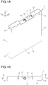
- Figures 1A and 1B are respectively a perspective view and a top view conceptually illustrating an electricity storage device.
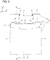
- Figures 2 and 3 are respectively an exploded perspective view and an exploded front view of the electricity storage device.
- the electricity storage device includes a case 1, an electrode group 2, a positive electrode external terminal 3, a negative electrode external terminal 4, a positive electrode connecting member 5, and a negative electrode connecting member 6.
- the case 1 is a case in which the electrode group 2 and an electrolyte are accommodated and includes a first main wall 11 and a second main wall 12 that face each other, a first side wall 13 and a second side wall 14 through which the first main wall 11 and the second main wall 12 are coupled with each other at both sides of the first main wall 11 and the second main wall 12, a top wall 15, and a bottom wall 16.
- the direction from the first side wall 13 toward the second side wall 14 (the width direction of the electricity storage device) is defined as an X direction
- the direction from the first main wall 11 toward the second main wall 12 (the thickness direction of the electricity storage device) is defined as a Y direction
- the direction from the bottom wall 16 toward the top wall 15 (the height direction of the electricity storage device) is defined as a Z direction.
- the case 1 is preferably made of a metal such as aluminum or an alloy such as stainless steel for the purpose of improving the corrosion resistance of the case 1.
- a square groove-type recess 17 is formed on the top wall 15 of the case 1.
- the recess 17 extends in the Y direction and has openings to both the first main wall 11 and the second main wall 12. Therefore, the first main wall 11 and the second main wall 12 each have an angular U-shaped cut formed so as to open the recess 17.
- a first accommodating portion 18 and a second accommodating portion 19 are formed on the left and right sides of the recess 17.
- Positive electrode tabs 24 described below are accommodated in the first accommodating portion 18, and negative electrode tabs 25 described below are accommodated in the second accommodating portion 19. That is, in the assembled electricity storage device, the recess 17 has such a shape that the recess 17 is depressed to a position between the positive electrode tabs 24 and the negative electrode tabs 25.
- a safety valve 81 and a stopper 82 that closes an injection hole for the electrolyte are disposed on the bottom surface of the recess 17.
- the case 1 includes a cylindrical exterior can 71 having a closed bottom and a lid member 72 that seals an opening 71a of the exterior can 71.
- the exterior can 71 constitutes the first main wall 11, the second main wall 12, the first side wall 13, the second side wall 14, and the bottom wall 16 in the case 1.
- the lid member 72 constitutes the top wall 15 on which the recess 17 is formed in the case 1.
- Figure 2 illustrates a state in which the electrode group 2 is slightly drawn from the opening 71a of the exterior can 71.
- FIG. 4 is a sectional view of the electricity storage device taken along line IV-IV in Fig. 3 .
- the electrode group 2 is formed by alternately stacking a plurality of positive electrode plates 21 and a plurality of negative electrode plates 22 with separators 23 disposed therebetween.
- each of the positive electrode plates 21 is accommodated in a bag 28 formed by two adjacent separators 23 that sandwich the positive electrode plate 21.
- the bag 28 is formed by pressure-bonding the edges of the two separators 23.
- the electrode group 2 is accommodated in the case 1 while both end surfaces 2b and 2c of the electrode group 2 in the stacking direction (Y direction) of the positive electrode plates 21 and the negative electrode plates 22 face the inner surface of the first main wall 11 and the inner surface of the second main wall 12, respectively. Furthermore, as illustrated in Fig. 2 and Fig. 3 , in the assembled electricity storage device, a plurality of positive electrode tabs 24 disposed on the plurality of positive electrode plates 21 at a position close to the first side wall 13 and a plurality of negative electrode tabs 25 disposed on the plurality of negative electrode plates 22 at a position close to the second side wall 14 protrude from an end surface 2a of the electrode group 2 in a direction toward the top wall 15. This is specifically described below.
- the positive electrode plates 21 and the negative electrode plates 22 each have a rectangular shape.
- Each of the positive electrode plates 21 has a positive electrode tab 24 disposed at a position close to one end (an end that will be located on the side of the first side wall 13) of one side of the assembled electricity storage device in a direction toward the top wall 15.
- Each of the negative electrode plates 22 has a negative electrode tab 25 at a position close to the other end (an end that will be located on the side of the second side wall 14) of the one side of the assembled electricity storage device in the direction toward the top wall 15.
- the positive electrode plates 21 and the negative electrode plates 22 are alternately stacked so that the positive electrode tabs 24 face each other and the negative electrode tabs 25 face each other at a position away from the positive electrode tabs 24.
- a conductive spacer 27 is disposed between the two adjacent positive electrode tabs 24 to prevent the deformation of the positive electrode plates 21 and the positive electrode tabs 24.
- a metal porous body such as Aluminum-Celmet (registered trademark), which is easily deformed by external forces, is used as the positive electrode plate 21.
- all the negative electrode tabs 25 are also fastened by a rivet 26.
- a conductive spacer is disposed between the two adjacent negative electrode tabs 25 to prevent the deformation of the negative electrode plates 22 and the negative electrode tabs 25.
- the positive electrode external terminal 3 is electrically connected to the positive electrode plates 21 through the positive electrode tabs 24.
- the negative electrode external terminal 4 is electrically connected to the negative electrode plates 22 through the negative electrode tabs 25.
- the positive electrode external terminal 3 and the negative electrode external terminal 4 are disposed on the lid member 72 constituting the top wall 15 of the case 1.
- the positive electrode external terminal 3 is disposed on an inner wall 171 of the recess 17, the inner wall 171 being located on the side of the first accommodating portion 18 (refer to Fig. 1A ).
- the negative electrode external terminal 4 is disposed on an inner wall 172 of the recess 17, the inner wall 172 being located on the side of the second accommodating portion 19 (refer to Fig. 1A ). That is, the positive electrode external terminal 3 is drawn in the X direction, and the negative electrode external terminal 4 is drawn in a direction opposite to the X direction.
- FIG. 5 is an enlarged sectional view of a principal part taken along line V-V in Fig. 1B .
- Fig. 5 is a sectional view illustrating the positive electrode external terminal 3 and its surrounding structure.
- the positive electrode external terminal 3 is a rivet-type terminal and includes a rivet head portion 31 and a rivet leg portion 32.
- the rivet head portion 31 includes a protrusion 31a engaged with a fitting hole 52a of a positive electrode connecting member 5 described below.
- a through-hole 173 into which the rivet leg portion 32 of the positive electrode external terminal 3 is inserted and which prevents the rivet head portion 31 of the positive electrode external terminal 3 from passing through the through-hole 173 is formed in the inner wall 171 of the recess 17.
- the diameter of the through-hole 173 is designed to be larger than the diameter of the rivet leg portion 32.
- the positive electrode external terminal 3 is installed in the inner wall 171 of the recess 17 as follows. First, the rivet leg portion 32 is inserted into a ring gasket 33 made of a rubber material. Subsequently, the rivet leg portion 32 with the ring gasket 33 is inserted into the through-hole 173 while the rivet head portion 31 is positioned inside the case 1. Thus, the ring gasket 33 is interposed between the rivet head portion 31 and the inner wall 171. Then, a ring gasket 34 made of a resin material is attached to the rivet leg portion 32 so that the ring gasket 34 and the ring gasket 33 sandwich the inner wall 171.
- the rivet leg portion 32 passes through the ring gasket 34. Then, the tip of the rivet leg portion 32 is riveted to fix the positive electrode external terminal 3 to the inner wall 171.
- the ring gaskets 33 and 34 are sandwiched between the rivet head portion 31 of the positive electrode external terminal 3 and the resulting riveted portion 35, which compresses the ring gasket 33 made of a rubber material. Consequently, a part of the ring gasket 33 enters a space between the inner surface of the through-hole 173 and the rivet leg portion 32.
- the positive electrode external terminal 3 is installed in the inner wall 171 while the positive electrode external terminal 3 and the lid member 72 are electrically insulated from each other by the ring gaskets 33 and 34.
- the negative electrode external terminal 4 is also a rivet-type terminal like the positive electrode external terminal 3, and is installed in the inner wall 172 of the recess 17 by the same installation method as described above.
- the positive electrode connecting member 5 is a member for electrically connecting the positive electrode tabs 24 and the positive electrode external terminal 3 to each other.
- the positive electrode connecting member 5 is formed by bending a single metal plate into an L shape and includes a first tabular portion 51 and a second tabular portion 52.
- the positive electrode connecting member 5 is disposed so that the first tabular portion 51 faces the positive electrode tabs 24 as illustrated in Fig. 4 and the second tabular portion 52 faces the inner wall 171 of the recess 17 as illustrated in Fig. 5 .
- the first tabular portion 51 is fixed to the positive electrode tabs 24 with the rivet 26 used to fasten the positive electrode tabs 24.
- the second tabular portion 52 has a fitting hole 52a.
- the protrusion 31a on the rivet head portion 31 of the positive electrode external terminal 3 is engaged with the fitting hole 52a.
- the second tabular portion 52 and the positive electrode external terminal 3 are connected to each other.
- the shape of the positive electrode connecting member 5 is not limited to the shape in this embodiment.
- a positive electrode connecting member having a different shape may be used as long as the positive electrode tabs 24 and the positive electrode external terminal 3 can be electrically connected to each other.
- the negative electrode connecting member 6 is a member for electrically connecting the negative electrode tabs 25 and the negative electrode external terminal 4 to each other.
- the shape of the negative electrode connecting member 6 and the connecting form between the negative electrode tabs 25 and the negative electrode external terminal 4 through the negative electrode connecting member 6 are the same as those of the positive electrode connecting member 5 described above.
- the presence of the recess 17 eliminates a useless space of the case in the rectangular electricity storage device.
- the occupation ratio of the electrode group 2 in the electricity storage device is increased to 90% or more.
- the occupation ratio of the electrode group 2 in this electricity storage device can be increased to 93% or more. Therefore, a volumetric energy density much higher than that of conventional electricity storage devices is achieved.
- the recesses 17 formed in the electricity storage devices form a single long groove 174.
- a cable such as a harness
- the positive electrode external terminal 3 is drawn in the X direction
- the negative electrode external terminal 4 is drawn in a direction opposite to the X direction (refer to Fig. 3 ). That is, the positive electrode external terminal 3 and the negative electrode external terminal 4 are drawn in the width direction of the electricity storage device. Therefore, in the electricity storage device according to this embodiment, the positive electrode external terminal 3 and the negative electrode external terminal 4 have high strength to vibration in the width direction of the electricity storage device.
- Figure 7 is an exploded perspective view illustrating an electricity storage device according to a first modification.
- the structure of the case 1 having a difference from the electricity storage device according to the above embodiment will be mainly described in detail.
- the case 1 includes a cylindrical exterior can 73 having a closed bottom and a lid member 74 that seals an opening 73a of the exterior can 73.
- the exterior can 73 constitutes the top wall 15 on which the recess 17 is formed, the second main wall 12, the first side wall 13, the second side wall 14, and the bottom wall 16 in the case 1.
- the lid member 74 constitutes the first main wall 11 in the case 1.
- the presence of the recess 17 eliminates a useless space of the case in the rectangular electricity storage device like the electricity storage device according to the above embodiment.
- the occupation ratio of the electrode group 2 in the electricity storage device is increased to 90% or more.
- the occupation ratio of the electrode group 2 in this electricity storage device can be increased to 93% or more. Therefore, a volumetric energy density much higher than that of conventional electricity storage devices is achieved.
- Figure 8 is an exploded perspective view illustrating an electricity storage device according to a second modification.
- the structure of the case 1 having a difference from the electricity storage device according to the above embodiment will be mainly described in detail.
- the case 1 includes an upper case part 75 and a lower case part 76 joined to each other along a plane substantially parallel to the bottom wall 16.
- substantially parallel means "parallel” or "parallel ⁇ 1 degree”.
- the lower case part 76 is a cylindrical exterior can having a closed bottom and including a portion to serve as the bottom wall 16 in the case 1.
- the upper case part 75 is a lid member that seals an opening 76a of the lower case part 76 and includes a portion to serve as the top wall 15 in the case 1.
- Figure 8 illustrates a state in which the electrode group 2 is slightly drawn from the opening 76a of the lower case part 76.
- the presence of the recess 17 eliminates a useless space of the case in the rectangular electricity storage device like the electricity storage device according to the above embodiment.
- the occupation ratio of the electrode group 2 in the electricity storage device is increased to 90% or more.
- the occupation ratio of the electrode group 2 in this electricity storage device can be increased to 93% or more. Therefore, a volumetric energy density much higher than that of conventional electricity storage devices is achieved.
- At least one of the positive electrode external terminal 3 and the negative electrode external terminal 4 may be disposed at a position other than the inner wall of the recess 17 on the top wall 15 of the case 1.
- the electricity storage device according to the present invention is useful as, for example, large-scale power storage apparatuses for household use or industrial use.
Landscapes
- Engineering & Computer Science (AREA)
- Power Engineering (AREA)
- Chemical & Material Sciences (AREA)
- Chemical Kinetics & Catalysis (AREA)
- Electrochemistry (AREA)
- General Chemical & Material Sciences (AREA)
- Microelectronics & Electronic Packaging (AREA)
- Manufacturing & Machinery (AREA)
- Materials Engineering (AREA)
- Sealing Battery Cases Or Jackets (AREA)
- Connection Of Batteries Or Terminals (AREA)
- Secondary Cells (AREA)
- Electric Double-Layer Capacitors Or The Like (AREA)
Applications Claiming Priority (2)
| Application Number | Priority Date | Filing Date | Title |
|---|---|---|---|
| JP2014020668A JP2015149362A (ja) | 2014-02-05 | 2014-02-05 | 蓄電デバイス |
| PCT/JP2015/052439 WO2015119027A1 (fr) | 2014-02-05 | 2015-01-29 | Dispositif de stockage d'energie electrique |
Publications (2)
| Publication Number | Publication Date |
|---|---|
| EP3104384A1 true EP3104384A1 (fr) | 2016-12-14 |
| EP3104384A4 EP3104384A4 (fr) | 2017-03-15 |
Family
ID=53777834
Family Applications (1)
| Application Number | Title | Priority Date | Filing Date |
|---|---|---|---|
| EP15745750.8A Withdrawn EP3104384A4 (fr) | 2014-02-05 | 2015-01-29 | Dispositif de stockage d'energie electrique |
Country Status (6)
| Country | Link |
|---|---|
| US (1) | US20160351345A1 (fr) |
| EP (1) | EP3104384A4 (fr) |
| JP (1) | JP2015149362A (fr) |
| KR (1) | KR20160117431A (fr) |
| CN (1) | CN105960693A (fr) |
| WO (1) | WO2015119027A1 (fr) |
Families Citing this family (9)
| Publication number | Priority date | Publication date | Assignee | Title |
|---|---|---|---|---|
| CN107431153B (zh) * | 2015-03-31 | 2021-05-07 | 株式会社杰士汤浅国际 | 蓄电元件 |
| JP6593304B2 (ja) | 2016-11-07 | 2019-10-23 | トヨタ自動車株式会社 | 蓄電デバイスおよび蓄電デバイスの製造方法 |
| JP6697685B2 (ja) * | 2017-02-06 | 2020-05-27 | トヨタ自動車株式会社 | 密閉型電池および組電池 |
| JP6970912B2 (ja) * | 2017-09-12 | 2021-11-24 | 株式会社Gsユアサ | 蓄電素子、及び蓄電素子を備える蓄電装置 |
| CN117795717A (zh) * | 2021-10-13 | 2024-03-29 | 株式会社杰士汤浅国际 | 蓄电元件 |
| EP4407758A4 (fr) * | 2021-11-01 | 2025-08-27 | Contemporary Amperex Technology Hong Kong Ltd | Élément de batterie, batterie, dispositif électrique, et procédé et dispositif de fabrication d'élément de batterie |
| CN216872125U (zh) * | 2022-02-21 | 2022-07-01 | 宁德时代新能源科技股份有限公司 | 电池单体、电池和用电设备 |
| CN217719785U (zh) * | 2022-07-19 | 2022-11-01 | 宁德时代新能源科技股份有限公司 | 电池单体、电池及用电装置 |
| WO2024045048A1 (fr) * | 2022-08-31 | 2024-03-07 | 宁德时代新能源科技股份有限公司 | Élément de batterie, batterie et dispositif électrique |
Family Cites Families (13)
| Publication number | Priority date | Publication date | Assignee | Title |
|---|---|---|---|---|
| CN1655389A (zh) * | 2005-03-04 | 2005-08-17 | 北京中信国安盟固利新材料技术研究院有限公司 | 大容量金属外壳锂离子二次电池 |
| GB0619444D0 (en) * | 2006-10-02 | 2006-11-08 | Enersys Ltd | A battery and a process of making a battery |
| JP5025276B2 (ja) * | 2007-01-31 | 2012-09-12 | 三洋電機株式会社 | アルカリ蓄電池およびその製造方法 |
| JP2009266695A (ja) * | 2008-04-25 | 2009-11-12 | Toyota Motor Corp | 電池の製造方法及び組電池 |
| JP4858726B2 (ja) * | 2009-01-07 | 2012-01-18 | 三菱自動車工業株式会社 | 二次電池の保持構造 |
| JP2011171079A (ja) * | 2010-02-17 | 2011-09-01 | Toshiba Corp | 電池 |
| JP2011204469A (ja) | 2010-03-25 | 2011-10-13 | Sanyo Electric Co Ltd | 角形密閉二次電池 |
| JP5543269B2 (ja) * | 2010-05-12 | 2014-07-09 | シャープ株式会社 | 二次電池 |
| JP2012114066A (ja) * | 2010-11-02 | 2012-06-14 | Sharp Corp | 二次電池 |
| CN103329303B (zh) * | 2011-01-31 | 2016-05-11 | 株式会社杰士汤浅国际 | 蓄电元件 |
| WO2012140707A1 (fr) * | 2011-04-11 | 2012-10-18 | パナソニック株式会社 | Accumulateur mince et dispositif accumulateur |
| JP6048080B2 (ja) * | 2011-11-29 | 2016-12-21 | 株式会社Gsユアサ | 蓄電素子 |
| JP5861524B2 (ja) * | 2012-03-23 | 2016-02-16 | 株式会社豊田自動織機 | 蓄電モジュール |
-
2014
- 2014-02-05 JP JP2014020668A patent/JP2015149362A/ja active Pending
-
2015
- 2015-01-29 KR KR1020167018436A patent/KR20160117431A/ko not_active Withdrawn
- 2015-01-29 EP EP15745750.8A patent/EP3104384A4/fr not_active Withdrawn
- 2015-01-29 CN CN201580006915.6A patent/CN105960693A/zh active Pending
- 2015-01-29 US US15/116,729 patent/US20160351345A1/en not_active Abandoned
- 2015-01-29 WO PCT/JP2015/052439 patent/WO2015119027A1/fr not_active Ceased
Also Published As
| Publication number | Publication date |
|---|---|
| JP2015149362A (ja) | 2015-08-20 |
| KR20160117431A (ko) | 2016-10-10 |
| EP3104384A4 (fr) | 2017-03-15 |
| US20160351345A1 (en) | 2016-12-01 |
| WO2015119027A1 (fr) | 2015-08-13 |
| CN105960693A (zh) | 2016-09-21 |
Similar Documents
| Publication | Publication Date | Title |
|---|---|---|
| EP3104384A1 (fr) | Dispositif de stockage d'energie electrique | |
| EP3748732B1 (fr) | Batterie secondaire | |
| KR101201744B1 (ko) | 이차 전지 | |
| KR101265202B1 (ko) | 이차 전지 | |
| KR101275791B1 (ko) | 이차 전지 및 그 모듈 | |
| US20150171404A1 (en) | Battery module | |
| CN102623711B (zh) | 电池 | |
| EP2824755A1 (fr) | Cellule à air | |
| CN107112488A (zh) | 蓄电元件 | |
| CN102544424A (zh) | 电池 | |
| JP6136407B2 (ja) | 電源モジュール | |
| CN104112830A (zh) | 电池模块 | |
| EP2843724A1 (fr) | Boîte pour bloc-batteries avec structure de drainage | |
| US20220384915A1 (en) | Non-aqueous electrolyte secondary battery | |
| JP2025539144A (ja) | 電気化学装置及び電気使用装置 | |
| KR20170060447A (ko) | 이차 전지 | |
| JP2017084540A (ja) | 蓄電素子 | |
| CN104798158B (zh) | 蓄电设备以及蓄电模块 | |
| CN114024082A (zh) | 电池、电池模组以及电池包 | |
| EP2790265B1 (fr) | Batterie à air | |
| EP3258518B1 (fr) | Bloc-batterie avec un fond d'epaisseur réduite et ordinateur portable comprenant le même | |
| JP2019175719A (ja) | 燃料電池システム | |
| US20150372283A1 (en) | Electricity Charging/Discharging Device With Insulation Package Enclose Member Having Electrode Plate Pair With Multiple-Sided Electric Conductive Terminals | |
| JP2016115408A (ja) | 蓄電素子 | |
| JP2003208879A (ja) | 二次電池 |
Legal Events
| Date | Code | Title | Description |
|---|---|---|---|
| PUAI | Public reference made under article 153(3) epc to a published international application that has entered the european phase |
Free format text: ORIGINAL CODE: 0009012 |
|
| STAA | Information on the status of an ep patent application or granted ep patent |
Free format text: STATUS: REQUEST FOR EXAMINATION WAS MADE |
|
| 17P | Request for examination filed |
Effective date: 20160729 |
|
| AK | Designated contracting states |
Kind code of ref document: A1 Designated state(s): AL AT BE BG CH CY CZ DE DK EE ES FI FR GB GR HR HU IE IS IT LI LT LU LV MC MK MT NL NO PL PT RO RS SE SI SK SM TR |
|
| AX | Request for extension of the european patent |
Extension state: BA ME |
|
| A4 | Supplementary search report drawn up and despatched |
Effective date: 20170210 |
|
| RIC1 | Information provided on ipc code assigned before grant |
Ipc: H01G 11/74 20130101ALI20170206BHEP Ipc: H01M 10/04 20060101ALI20170206BHEP Ipc: H01G 11/76 20130101ALI20170206BHEP Ipc: H01M 2/02 20060101ALI20170206BHEP Ipc: H01M 2/26 20060101ALI20170206BHEP Ipc: H01M 2/04 20060101ALI20170206BHEP Ipc: H01G 11/78 20130101AFI20170206BHEP |
|
| DAX | Request for extension of the european patent (deleted) | ||
| STAA | Information on the status of an ep patent application or granted ep patent |
Free format text: STATUS: THE APPLICATION IS DEEMED TO BE WITHDRAWN |
|
| 18D | Application deemed to be withdrawn |
Effective date: 20170912 |