EP3104639B1 - Utilisation d'indicateur de réduction de charge de la circulation pour faciliter la fonction de commande de surcharge d'entité pour la gestion de la mobilité - Google Patents
Utilisation d'indicateur de réduction de charge de la circulation pour faciliter la fonction de commande de surcharge d'entité pour la gestion de la mobilité Download PDFInfo
- Publication number
- EP3104639B1 EP3104639B1 EP16172883.7A EP16172883A EP3104639B1 EP 3104639 B1 EP3104639 B1 EP 3104639B1 EP 16172883 A EP16172883 A EP 16172883A EP 3104639 B1 EP3104639 B1 EP 3104639B1
- Authority
- EP
- European Patent Office
- Prior art keywords
- overload message
- message
- henb
- mme
- traffic load
- Prior art date
- Legal status (The legal status is an assumption and is not a legal conclusion. Google has not performed a legal analysis and makes no representation as to the accuracy of the status listed.)
- Active
Links
Images



Classifications
-
- H—ELECTRICITY
- H04—ELECTRIC COMMUNICATION TECHNIQUE
- H04L—TRANSMISSION OF DIGITAL INFORMATION, e.g. TELEGRAPHIC COMMUNICATION
- H04L47/00—Traffic control in data switching networks
- H04L47/10—Flow control; Congestion control
- H04L47/12—Avoiding congestion; Recovering from congestion
- H04L47/125—Avoiding congestion; Recovering from congestion by balancing the load, e.g. traffic engineering
-
- H—ELECTRICITY
- H04—ELECTRIC COMMUNICATION TECHNIQUE
- H04W—WIRELESS COMMUNICATION NETWORKS
- H04W28/00—Network traffic management; Network resource management
- H04W28/02—Traffic management, e.g. flow control or congestion control
- H04W28/0226—Traffic management, e.g. flow control or congestion control based on location or mobility
-
- H—ELECTRICITY
- H04—ELECTRIC COMMUNICATION TECHNIQUE
- H04L—TRANSMISSION OF DIGITAL INFORMATION, e.g. TELEGRAPHIC COMMUNICATION
- H04L12/00—Data switching networks
- H04L12/66—Arrangements for connecting between networks having differing types of switching systems, e.g. gateways
-
- H—ELECTRICITY
- H04—ELECTRIC COMMUNICATION TECHNIQUE
- H04W—WIRELESS COMMUNICATION NETWORKS
- H04W28/00—Network traffic management; Network resource management
- H04W28/02—Traffic management, e.g. flow control or congestion control
- H04W28/0289—Congestion control
-
- H—ELECTRICITY
- H04—ELECTRIC COMMUNICATION TECHNIQUE
- H04W—WIRELESS COMMUNICATION NETWORKS
- H04W28/00—Network traffic management; Network resource management
- H04W28/02—Traffic management, e.g. flow control or congestion control
- H04W28/10—Flow control between communication endpoints
- H04W28/12—Flow control between communication endpoints using signalling between network elements
-
- H—ELECTRICITY
- H04—ELECTRIC COMMUNICATION TECHNIQUE
- H04W—WIRELESS COMMUNICATION NETWORKS
- H04W8/00—Network data management
- H04W8/02—Processing of mobility data, e.g. registration information at HLR [Home Location Register] or VLR [Visitor Location Register]; Transfer of mobility data, e.g. between HLR, VLR or external networks
- H04W8/04—Registration at HLR or HSS [Home Subscriber Server]
-
- H—ELECTRICITY
- H04—ELECTRIC COMMUNICATION TECHNIQUE
- H04W—WIRELESS COMMUNICATION NETWORKS
- H04W24/00—Supervisory, monitoring or testing arrangements
- H04W24/02—Arrangements for optimising operational condition
-
- H—ELECTRICITY
- H04—ELECTRIC COMMUNICATION TECHNIQUE
- H04W—WIRELESS COMMUNICATION NETWORKS
- H04W92/00—Interfaces specially adapted for wireless communication networks
- H04W92/04—Interfaces between hierarchically different network devices
- H04W92/045—Interfaces between hierarchically different network devices between access point and backbone network device
Definitions
- This disclosure relates in general to the field of communications networks and, more particularly, to utilization of a traffic load reduction indicator for facilitating a mobility management entity (“MME”) overload control function in such networks.
- MME mobility management entity
- an MME overload control function is provided.
- a home e-Node B gateway (“HeNB-GW”) can aggregate tens of thousands to millions of HeNBs.
- the HeNB-GW needs to forward overload START/STOP messages to all HeNBs. Therefore, even if an MME is lightly loaded, the HeNBGW needs to send overload START/STOP messages to tens of thousands to millions of HeNBs, which greatly increases HeNB-GW processing load, as well as S1-MME interface signaling load in a short amount of time. As a result, HeNB-GW performance and availability is negatively impacted.
- US 2013/215742 relates to transmission of extended access baring action.
- US 2012069737 relates to handling signal connection establishment in systems which include home gateways.
- a method that includes determining whether a received overload message includes a traffic load reduction indication element; determining a percentage of network elements to which to relay the received overload message if the received overload message includes the traffic load reduction indication element; and selecting ones of the network elements to which to send the received overload message based on the determined percentage.
- the method may further include modifying the received message to change a value of the traffic load reduction indication element; and sending the modified message to the selected ones of the network elements.
- the received overload message includes a mobility management element ("MME") START message.
- MME mobility management element
- the method may further include sending the received overload message to all of the network elements if the received overload message does not include the traffic load reduction indication element.
- the method includes sending the received overload message to a configurable percentage of the network elements if the received overload message does not include the traffic load reduction indication element.
- Each of the network elements may be a Home eNodeB ("HeNB").
- the method may further include, prior to the determining whether the received overload message includes a traffic load reduction indication element, receiving at a gateway element the overload message.
- the gateway element may be an HeNB gateway disposed between an MME and the network elements.
- the selected network elements upon receipt of the modified overload message, perform traffic filtering based on the modified overload message.
- FIGURE 1 is a simplified block diagram of a portion of a communications network 10 for implementing a traffic load reduction indicator for assisting a mobility management entity (“MME”) overload control function in such networks.
- the network 10 is implemented as a Long Term Evolution (“LTE") network.
- LTE Long Term Evolution
- the network 10 enables one or more user equipment (“UE”), represented in FIGURE 1 by UE 12, to be connected to communicate data to and from the Internet 14 via a radio access network (“RAN”) 16 comprising a plurality of RAN nodes, represented in FIGURE 1 by eNBs 17A and HeNBs 17B, and a core network 18.
- RAN 16 is implemented as an E-UTRAN.
- the core network 18 may be implemented using an Evolved Packet Core (“EPC") network as defined in 3GPP TS 23.401 and employing a user plane protocol GTPv1-U. It will be understood, however, that other implementations of the core network 18 may be employed in accordance with the features described herein.
- EPC Evolved Packet Core
- the core network 18 may include a mobility management entity ("MME") 20, which is responsible for control plane functions related to subscriber and session management and is connected to a home subscriber service (“HSS”) (not shown), which supports a database that includes user subscription information, through an S6a interface.
- MME mobility management entity
- HSS home subscriber service
- the core network 18 may further include a serving GPRS support node (not shown) connected to the MME 20 via an S3 interface for providing functionality related to packet-data switching.
- the core network 18 may further include a serving gateway ("S-GW”), which in the illustrated embodiment is co-located with the MME 20 and which serves as the termination point of the user plane interface S1-U toward the RAN network 16, and a PDN gateway (“PGW”) 28, which serves as an interface to the Internet 14, sending user data from the user toward the Internet and receiving data destined for the user from the Internet.
- S-GW serving gateway
- PGW PDN gateway
- the PGW 28 supports policy enforcement features that apply operator-defined rules for resource allocation and usage, as well as packet filtering and inspection and charging support.
- the PGW 28 may interface with a policy charging rule function (“PCRF”) (not shown), which manages the service policy and provides QoS information for each user session.
- PCRF policy charging rule function
- the core network 18 may provide a variety of functionality in the network 10, including, for example, one or more of aggregation, user authentication, call control and switching, accounting and charging, service invocation, and gateways.
- the network 10 is implemented in accordance with the Long-Term Evolution ("LTE") standard.
- E-UTRAN provides the radio access in the LTE network and is designed to improve end-user throughputs and sector capacity and reduce user plan latency, bringing significantly improved user experience with full mobility.
- LTE provides support for IP-based traffic with end-to-end QoS.
- E-UTRAN supports various types of services, including web browsing, FTP, video streaming, VoIP, online gaming, real time video, push-to-talk, and push-to-view, for example.
- UE 12 can be associated with clients, customers, or end users wishing to initiate a communication in communication network 10 via some network.
- the term "user equipment” is inclusive of devices used to initiate a communication, such as a computer, a personal digital assistant (PDA), a laptop or electronic notebook, a cellular telephone, an iPhone, an IP phone, or any other device, component, element, or object capable of initiating voice, audio, video, media, or data exchanges within communication network 10.
- PDA personal digital assistant
- UE 12 may also be inclusive of a suitable interface to the human user, such as a microphone, a display, or a keyboard or other terminal equipment.
- UE 12 may also be any device that seeks to initiate a communication on behalf of another entity or element, such as a program, a database, or any other component, device, element, or object capable of initiating an exchange within communication network 10.
- Data refers to any type of numeric, voice, video, media, or script data, or any type of source or object code, or any other suitable information in any appropriate format that may be communicated from one point to another.
- UE 12 can be configured to initiate a request for a connection with a service provider.
- a user agreement can be authenticated by the service provider based on various service provider credentials (e.g., subscriber identity module ("SIM”), Universal SIM (“USIM”), certifications, etc.). More specifically, a device can be authenticated by the service provider using some predetermined financial relationship.
- SIM subscriber identity module
- USIM Universal SIM
- certifications etc.
- S-GW portion of MME/S-GW 20 is can be configured to route and to forward user data packets, while also acting as the mobility anchor for the user plane during inter-eNodeB handovers. Additionally, S-GW can act as the anchor for mobility between LTE and other 3GPP technologies.
- MME portion of MME/S-GW 20 can be configured to operate as a control node for the LTE access-network. It further can be responsible for idle mode UE tracking and paging procedures (including, for example, retransmissions). Furthermore, MME 20 can be involved in the bearer activation/deactivation process and can be responsible for choosing S-GW for UE 12 at the initial attach (and at time of an intra-LTE handover involving core network node relocation). MME 20 can also be responsible for authenticating the user by interacting with HSS 22. MME 20 also provides the control plane function for mobility between LTE and 2G/3G access networks.
- MME 20 may include generating and allocating temporary identities to UEs, terminating Non-Access Stratum ("NAS") signaling, checking the authorization of UE 12 to camp on a service provider's Public Land Mobile Network (“PLMN”), and enforcing UE roaming restrictions.
- NAS Non-Access Stratum
- PLMN Public Land Mobile Network
- MME 20 serves as the termination point in the network for ciphering/integrity protection for NAS signaling and handles the security key management. Lawful interception of signaling is also supported by MME 20.
- media servers comprising one or more video servers may be provided, which can provide streaming video to an individual associated with UE 12 via the Internet 14.
- an individual could be uploading (or streaming) video over the network to which UE 12 is connected. This could involve technologies such as flip video, webcams, YouTube, and various other video technologies involving any type of uploading and/or streaming video data.
- data packets intended for the UE 12 are transmitted to the UE from the Internet 14 via the S-GW and PGW, which encapsulates the same in accordance in GTPv1-U tunnel towards the RAN node, and the RAN node 17 decapsulates the data packets upon receipt thereof.
- the LTE standard includes a radio access network that employ a technology called evolved universal terrestrial radio access network ("EUTRAN”) for communicating UEs and a System Architecture Evolution (“SAE”) core network.
- EUTRAN evolved universal terrestrial radio access network
- SAE System Architecture Evolution
- an eNB provides a wireless air interface for bridging UEs to the SAE core network over a wired connection.
- the SAE core network includes management gateways such as the MME, forwarding gateways such as the S-GW, and PGWs.
- an IP connectivity access network bearer or evolved packet switch (“EPS") bearer
- EPS evolved packet switch
- the EPS bearer is similar to a packet data protocol ("PDP") context in the general packet radio service (“GPRS”) core network and includes a radio bearer between UE 12 and E-UTRAN 16, an S1 bearer between E-UTRAN 16 and S-GW 20, and an S5/S8 bearer between S-GW and PGW.
- PDP packet data protocol
- GPRS general packet radio service
- a generic IP tunnel or IP path may substitute for a bearer in some embodiments.
- the EPS bearer includes a data structure maintained by MME/S-GW 20, which includes subscriber information and session information for identifying the traffic flow carried by the bearer.
- S-GW uses bearer information to direct the incoming packets to the correct UE, such as UE 12.
- UE 12 likewise attaches bearer information to IP traffic bound for the core network, which S-GW uses to maintain IP sessions and direct packets to their destinations.
- the bearer also carries QoS information that applies to the traffic flow carried by the bearer.
- UE 12 When UE 12 initially attaches to E-UTRAN 16, UE 12 requests IP connectivity, and a bearer may be allocated by MME/S-GW 20 for providing IP services.
- the bearer is created, allocated, and tracked by MME 20 so that when UE 12 moves from one RAN to another, it can maintain the same bearer at MME 20.
- Data is sent via the bearer in conjunction with a S1-U tunnel from S-GW 20 to attached RAN node 17. If UE 12 goes idle, RAN node 17 and S-GW 20 are permitted to deallocate radio resources.
- Downlink data paging is the process by which an inactive, or idle, UE is contacted to receive data from an upstream source over the packet data network.
- a UE that is in an active state is associated with an eNB and has at least one active bearer. When the UE goes inactive, such as when it enters a low power mode, it releases all bearers.
- MME 20 issues paging requests to multiple eNBs, which is typically an expensive operation.
- S-GW may inform the relevant MME, in this case, MME 20, that data has arrived using a downlink data notification (DDN) message.
- DDN downlink data notification
- MME 20 may page inactive UE 12 and, if requested by UE 12, reestablish an S1-U tunnel from S-GW 20 to eNB 17 by triggering a Modify Bearer Request (MBRq) message toward S-GW.
- MRRq Modify Bearer Request
- the data may then be requested by UE 12 and retrieved from S-GW 20 over the preexisting bearer.
- a DDN message need not be sent by S-GW to the MME 20 every time new downstream data is received at S-GW 20.
- S-GW 20 typically does not send another DDN but instead waits for MME 20 to respond with a message indicating that the DDN message has been received.
- This message may be a MBRq message or a DDN Acknowledgement (ACK) message.
- ACK DDN Acknowledgement
- S-GW 20 does not need to send additional DDN messages until a delay value timer has expired, indicating that a new DDN message should be sent.
- the delay value timer has a value which may be provided by MME 20 in a DDN ACK message, as described below, and which may be specific to UE 12 or to the particular packet data network that is the source of the incoming traffic.
- MME may not receive DDN messages from S-GW 20, which may also be overloaded; it may not page all the UEs for which it has received DDN messages; and/or it may fail to respond to S-GW with DDN ACK messages. MME may also become unable to page a UE during emergency events with the appropriate messages, e.g., Emergency Calls or Amber Alerts. Clearly, therefore, it is undesirable to permit overloading of an MME.
- LTE and the GPRS tunneling protocol (“GTP”) which incorporate a QoS model for EPS bearers.
- Each EPS bearer is associated with and identified by bearer level QoS parameters, including a QoS Class Identifier ("QCI") and Allocation and Retention Priority ("ARP").
- QCI QoS Class Identifier
- ARP Allocation and Retention Priority
- the QCI is a scalar that is used as a reference to access node-specific parameters that control bearer level packet forwarding treatment, such as scheduling weights, admission thresholds, queue management thresholds, link layer protocol configuration, for example, and that have been preconfigured by the operator that owns the access node (e.g., eNB).
- the ARP contains information about priority level (in the form of a scalar), preemption capability (in the form of a flag), and preemption vulnerability (in the form of a flag) of the bearer.
- the primary purpose of the ARP is to determine whether a bearer establishment/modification request can be accepted or needs to be rejected in case of resource limitations, such as available radio capacity, in the case of guaranteed bit rate ("GBR") bearers.
- the priority level information of the ARP is used for this decision to ensure that the request of the bearer with the higher priority is preferred.
- the ARP can be used (e.g., by the eNB) to determine which bearer(s) to drop during periods of exceptional resource limitation (e.g., at handover).
- the preemption capability information of the ARP is used to decide whether a bearer with a lower ARP priority level should be dropped to free up the required resources.
- the preemption vulnerability information of the ARP is used to decide whether a bearer is a candidate for such dropping by a preemption capable bearer with a higher ARP priority value.
- the value of the ARP priority level may be in a range of integers 1-15 and may be implemented to include a bearer priority value, with a value of 1 corresponding to the highest priority and a value of 15 corresponding to the lowest priority.
- the ARP may be included as a parameter in the DDN ACK message.
- a bearer priority is not provided by the MME, a default bearer priority will be applied.
- an MME may be configured to restrict the signaling load that S-GW is imposing on it via DDNs. For example, the MME can reject DDN requests for low priority traffic for UEs in idle mode.
- GPRS General Packet Radio Service
- the MME can request S-GW selectively to reduce the number of DDN requests it sends for low priority downlink traffic received for UEs in idle mode according to a throttling factor ("TF") for a period of time designated a throttling delay ("TD").
- TF throttling factor
- TD throttling delay
- an HeNB-GW 30 is an HeNB network access concentrator used to control capabilities necessary for managing large clusters of HeNBs, such as HeNBs 17B.
- the HeNB-GW 30 aggregates the HeNBs into a single network element and then connects to the LTE core network 18.
- the primary function of HeNBs 17B is to facilitate simple, seamless, and highly secure access to UEs as they roam between trusted/secure mobile networks and untrusted/insecure public networks.
- FIGURE 2A illustrates a simplified block diagram of an LTE small cell network 50 including an HeNB (also referred to as a "femtocell") 52 and an HeNB-GW 54 that provides access to a core network 56.
- an S1 interface is defined as an interface between HeNB-GW 54 and the core network 56, between the HeNB 52 and the HeNB-GW 54, and between the HeNB 52 and the core network 56.
- HeNB-GW 54 provides standards-based S1-MME and S1-U network interfaces.
- the HeNB-GW 54 appears to the MME of the core network 56 as an eNB and appears to the HeNB 52 as an MME.
- the S1 interface is provided between the HeNB 52 and the core network 56 whether or not the HeNB is connected to the core network via the HeNB-GW 54.
- the HeNB-GW 54 provides a variety of functions, including relaying UE-associated S1 application part messages between the MME serving the UE and the HeNB serving the UE; terminating non-UE associated S1 application part procedures toward the HeNB and the MME; optionally terminating the S1-U interface with the HeNB and the S-GW; supporting tracking area code ("TAC”) and PLMN ID used by the HeNB; allowing no X2 interface establishment between the HeNB-GW and other nodes, and optionally performing paging optimization in case the allowed closed subscriber group ("CSG”) list for the paged UE is included in the PAGING message.
- TAC tracking area code
- PLMN ID used by the HeNB
- MME hosts a variety of functions to support HeNB-GW, including CSG reporting to S-GW/P-GW; access control for UEs that are members of the CSG; and optionally performing paging optimization.
- the network 50 may further include a security gateway ("Se-GW”) 57, an HeNB Management System (“HeMS”) 58, and a CSG List Server (not shown).
- Se-GW security gateway
- HeMS HeNB Management System
- CSG List Server not shown.
- FIGURE 2B is a simplified block diagram illustrating S1-MME aggregation functionality of a HeNB access network 60 in accordance with embodiments described herein.
- the HeNB access network may include one or more HeNBs 62, an Se-GW 57 ( FIGURE 2A ), an HeNB-GW 64, an HeMS 58 ( FIGURE 2A ) and a CSG List Server (not shown).
- Each of the HeNBs 62 is customer premises equipment that offers Uu interface to UE and S1 interface over an IPsec tunnel to HeNB-GW 64for accessing LTE core network.
- an HeNB is directly connected to one and only one HeNB-GW.
- a SeGW is a logical function on the HeNB-GW 64 and may be implemented as either a separate physical entity or may be collocated with an existing entity.
- the SeGW secures the communication from/to the HeNBs 62.
- SeGW also authenticates HeNBs 62, terminates encrypted IPsec data connections from HeNBs, and provides access to HeMS and HeNB-GW 64.
- the HeNB-GW 64 provides access to the core network. It acts as an access gateway to each HeNB 62 and concentrates connections from a large number of HeNBs.
- HeNB-GW 64 services as a control plane concentrator specifically for the S1-MME interface to an MME 66.
- the HeNB-GW 64 may optionally terminate the user plane toward the HeNB 62 and toward the S-GW ( FIGURE 1 ) and may provide a relay function for relaying user plane data between the HeNB and the S-GW ( FIGURE 1 ).
- HeNB-GW 64 functions as an aggregation point between HeNBs 62 and MME 66.
- HeNB-GW 64 provides a single Stream Control Transmission Protocol ("SCTP") connection 68 toward the MME 66 and a single SCTP connection 70 to each HeNB 62.
- SCTP Stream Control Transmission Protocol
- HeNB-GW 64 functions to hide HeNB SCTP connections 70 from the MME 66. This reduces the number of SCTP connections to be handled by the MME 66, reduces SCTP capacity load on MME 66, reduces SCTP heartbeat load on MME, and eliminates maintenance of a large number of SCTP associations, as well as the frequent establishment and release of such associations, by MME.
- the MME 66 includes mechanisms for avoiding and handling overload situations, which may include the use of NAS signaling to reject NAS requests from UEs. Additionally, under certain circumstances, the MME may restrict the load that eNBs connected thereto are generating on it. This can be achieved by the MME invoking the S1 interface overload procedure to a proportion of the eNBs with which the MME has S1 interface connections. To reflect the amount of load that the MME wishes to reduce, the MME can adjust the proportion of eNBs which are sent an S1 interface OVERLOAD START message, and the content of the OVERLOAD START message.
- the MME should select the eNBs at random so that if two MMEs within a pool are overloaded, they do not both send OVERLOAD START messages to the exact same set of eNBs.
- the MME can request an eNB to reject all Radio Resource Control ("RRC") connection requests that are for non-emergency and non-high priority mobile originated services; reject all new RRC connection requests for EPS Mobility Management signaling (e.g. for TA Updates) for that MME; only permit RRC connection requests for emergency sessions and mobile terminated services for that MME; or only permit RRC connection requests for high priority sessions and mobile terminated services for that MME.
- RRC Radio Resource Control
- the eNB When rejecting an RRC connection request for overload reasons the eNB indicates to the UE an appropriate timer value that functions to limit additional RRC connection requests during that time period.
- the MME can request the eNB to restrict the load from subcategories of UEs. These subcategories include UEs that reselect from other PLMNs ("PLMN type") and all UEs using low access priority for the radio access. PLMN type barring can for example be used to protect a VPLMN from an overload caused by the failure of one (or more) other networks in that country and accesses made from roaming subscribers.
- PLMN type barring can for example be used to protect a VPLMN from an overload caused by the failure of one (or more) other networks in that country and accesses made from roaming subscribers.
- the MME should select all eNBs with which the MME has S1 interface connections. Alternatively, the selected eNBs may be limited to a subset of the eNBs with which the MME has an S1 interface connection . During an overload situation, the MME should attempt to maintain support for emergency bearer services. When the MME has recovered and wishes to increase its load for a particular subcategory, the MME sends an OVERLOAD STOP messages to the eNB(s), specifying the subcategory or subcategories of UEs in connection with which to lift restrictions.
- an HeNB-GW on receiving an MME OVEROAD START message, uses a Traffic Load Reduction Indication IE of the OVERLOAD START message to determine the percentage of HeNBs attached to the same logical eNB that receives the message to which the OVERLOAD START message needs to be relayed. It will be recognized that the logical eNB behaves as a virtual eNB toward the MME.
- the Traffic Load Reduction Indication IE indicates the percentage of the type of traffic relative to the instantaneous incoming rate at the eNB (as indicated in an Overload Action IE of the OVERLOAD START message), to be rejected
- the HeNB-GW will relay the message to a configurable percentage of HeNBs.
- a logic eNB of the HeNB-GW will create an overload control HeNB List ("OCHL") per MME for all HeNBs to which the OVERLOAD START message has been relayed so that subsequent OVERLOAD START/STOP messages can be correlated.
- OCHL overload control HeNB List
- HeNB-GW logic eNB receives another OVERLOAD START message from the same MME before receiving an OVERLOAD STOP message, if there is a TLRI IE and the percentage is changed from the previous OVERLOAD START message, the HeNB-GW calculates the difference and either relays the message to more HeNBs (adding to the OCHL) or sends an OVERLOAD STOP message to a subset of HeNBs in OCHL. The number of HeNBs in OCHL will match the new percentage. Otherwise, if the newly received OVERLOAD START message has the same actions, the new message will be dropped by the HeNB-GW. If the newly received OVERLOAD START message has different actions, the new message will be forwarded to the newly adjusted HeNBs in OCHL.
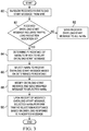
- FIGURE 3 illustrated therein is a flowchart of a method for using MME OVERLOAD START Traffic Load Reduction Indicator IE for assisting the MME perform overload control functions in accordance with embodiments described herein.
- HeNB-GW receives an MME OVERLOAD START message.
- a determination is made whether the received OVERLOAD START message includes a Traffic Load Reduction Indication IE. If a positive determination is made in step 82, in step 84, HeNB-GW uses the Traffic Load Reduction Indication IE to determine the percentage of HeNBs to which the OVERLOAD START message needs to be relayed.
- HeNB-GW selects HeNBs to receive the OVERLOAD START message.
- selection of HeNBs by the HeNB-GW is purely random, similar to MME selection of eNBs.
- the Traffic Load Reduction Indication IE in the OVERLOAD START message is modified to 99% so that selected HeNBs do not take further action based on the IE and the modified OVERLOAD START message is sent to the selected HeNBs.
- step 90 upon receipt of the modified OVERLOAD START message, the selected HeNBs perform traffic rejection/acceptance based on an Overload Response IE in the modified OVERLOAD START message. If a negative determination is made in step 82, execution proceeds to step 92, in which the OVERLOAD START message received from the MME is relayed by the HeNB-GW to all (or a configurable percentage) of the HeNBs.
- FIGURE 4 a flow diagram of a method for using MME OVERLOAD START Traffic Load Reduction Indicator IE for assisting the MME perform overload control functions in accordance with embodiments described herein is depicted.
- an OVERLOAD START message (which includes an Overload Response IE and a Traffic Load Rejection Indication IE) 113 is sent to an HeNB-GW 114.
- the HeNB-GW 114 computes the percentage of HeNBs to be sent the OVERLOAD START message based on the received Traffic Load Rejection Indication IE (115a), modifies the Traffic Load Rejection Indication IE to the maximum value (99) so that the HeNB does not filter traffic (115B), and forwards the modified OVERLOAD START message to select HeNBs, represented in FIGURE 4 by an HeNB 116 (115c).
- the HeNB-GW 114 modifies the OVERLOAD START message by deleting the Traffic Load Rejection Indication IE from the message altogether before sending it to the selected HeNBs.
- the HeNB 116 accepts/rejects traffic based on the Overload Action IE included in the message 118 (120).
- Embodiments described herein mitigate the performance impact on HeNB-GWs upon receipt of an MME OVERLOAD START/STOP message by requiring that each HeNB-GW send the message only to a percentage (based on the value of the Traffic Load Reduction Indication IE) of randomly-selected HeNBs connected to the HeNB-GW.
- the result is functionally equivalent to 3GPP-defined MME overload control.
- embodiment described herein reduce backhaul signaling load on an S1 interface between HeNBs and HeNB-GW, reduces HeNB-GW signaling processing load, and reduces overall HeNB overload control processing load in the HeNB. Only selected HeNBs have to perform traffic rejection/acceptance rather than all HeNBs in the network based on the Overload Action IE.
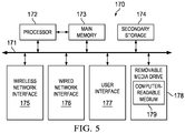
- FIGURE 5 is a simplified block diagram of an example machine (or apparatus) 170 that may be implemented as an element of a system for use in implementing a technique in accordance with embodiments described herein.
- the example machine 170 corresponds to network elements and computing devices that may be deployed in network 10, including, for example, HeNB-GWs 30, 54, 64, and/or 114.
- FIGURE 5 illustrates a block diagram representation of an example form of a machine within which software and hardware cause machine 170 to perform any one or more of the activities or operations discussed herein.
- machine 170 may include a processor 172, a main memory 173, secondary storage 174, a wireless network interface 175, a wired network interface 176, a user interface 177, and a removable media drive 178 including a computer-readable medium 179.
- a bus 171, such as a system bus and a memory bus, may provide electronic communication between processor 172 and the memory, drives, interfaces, and other components of machine 170.
- Processor 172 which may also be referred to as a central processing unit (“CPU"), can include any general or special-purpose processor capable of executing machine readable instructions and performing operations on data as instructed by the machine readable instructions.
- Main memory 173 may be directly accessible to processor 172 for accessing machine instructions and may be in the form of random access memory (“RAM”) or any type of dynamic storage (e.g., dynamic random access memory (“DRAM”)).
- Secondary storage 174 can be any non-volatile memory such as a hard disk, which is capable of storing electronic data including executable software files.
- Externally stored electronic data may be provided to computer 170 through one or more removable media drives 178, which may be configured to receive any type of external media such as compact discs ("CDs”), digital video discs (“DVDs”), flash drives, external hard drives, etc.
- CDs compact discs
- DVDs digital video discs
- flash drives external hard drives, etc.
- Wireless and wired network interfaces 175 and 176 can be provided to enable electronic communication between machine 170 and other machines via networks (e.g., control plane 108, data plane 110.
- wireless network interface 175 could include a wireless network controller ("WNIC") with suitable transmitting and receiving components, such as transceivers, for wirelessly communicating within a network.
- Wired network interface 176 can enable machine 170 to physically connect to a network by a wire line such as an Ethernet cable.
- Both wireless and wired network interfaces 175 and 176 may be configured to facilitate communications using suitable communication protocols such as, for example, Internet Protocol Suite ("TCP/IP").
- TCP/IP Internet Protocol Suite
- Machine 170 is shown with both wireless and wired network interfaces 175 and 176 for illustrative purposes only. While one or more wireless and hardwire interfaces may be provided in machine 170, or externally connected to machine 170, only one connection option is needed to enable connection of machine 170 to a network.
- a user interface 177 may be provided in some machines to allow a user to interact with the machine 170.
- User interface 177 could include a display device such as a graphical display device (e.g., plasma display panel ("PDP"), a liquid crystal display (“LCD”), a cathode ray tube (“CRT”), etc.).
- a display device such as a graphical display device (e.g., plasma display panel ("PDP"), a liquid crystal display (“LCD”), a cathode ray tube (“CRT”), etc.).
- PDP plasma display panel
- LCD liquid crystal display
- CRT cathode ray tube
- any appropriate input mechanism may also be included such as a keyboard, a touch screen, a mouse, a trackball, voice recognition, touch pad, etc.
- Removable media drive 178 represents a drive configured to receive any type of external computer-readable media (e.g., computer-readable medium 179).
- Instructions embodying the activities or functions described herein may be stored on one or more external computer-readable media. Additionally, such instructions may also, or alternatively, reside at least partially within a memory element (e.g., in main memory 173 or cache memory of processor 172) of machine 170 during execution, or within a non-volatile memory element (e.g., secondary storage 174) of machine 170. Accordingly, other memory elements of machine 170 also constitute computer-readable media.
- “computer-readable medium” is meant to include any medium that is capable of storing instructions for execution by machine 170 that cause the machine to perform any one or more of the activities disclosed herein.
- Machine 170 may include any additional suitable hardware, software, components, modules, interfaces, or objects that facilitate the operations thereof. This may be inclusive of appropriate algorithms and communication protocols that allow for the effective protection and communication of data. Furthermore, any suitable operating system may also be configured in machine 170 to appropriately manage the operation of the hardware components therein.
- machine 170 The elements, shown and/or described with reference to machine 170, are intended for illustrative purposes and are not meant to imply architectural limitations of machines such as those utilized in accordance with the present disclosure. In addition, each machine may include more or fewer components where appropriate and based on particular needs.
- machine is meant to encompass any computing device or network element such as servers, routers, personal computers, client computers, network appliances, switches, bridges, gateways, processors, load balancers, wireless LAN controllers, firewalls, or any other suitable device, component, element, or object operable to affect or process electronic information in a network environment.
- At least some portions of the activities related to the system described hererin may be implemented in software in, for example, HeNB-GWs 30, 54, 64, and/or 114.
- this software could be received or downloaded from a web server, provided on computer-readable media, or configured by a manufacturer of a particular element in order to provide this system for implementing autonomic LISP for enabling a secure hybrid cloud extension in accordance with features of embodiments described herein.
- one or more of these features may be implemented in hardware, provided external to these elements, or consolidated in any appropriate manner to achieve the intended functionality.
- each of HeNB-GWs 30, 54, 64, and/or 114 is a network or computing device that may include any suitable hardware, software, components, modules, or objects that facilitate the operations thereof, as well as suitable interfaces for receiving, transmitting, and/or otherwise communicating data or information in a network environment. This may be inclusive of appropriate algorithms and communication protocols that allow for the effective exchange of data or information.
- processors and memory elements associated with the various network elements may be removed, or otherwise consolidated such that a single processor and a single memory location are responsible for certain activities.
- certain processing functions could be separated and separate processors and/or physical machines could implement various functionalities.
- the arrangements depicted in the FIGURES may be more logical in their representations, whereas a physical architecture may include various permutations, combinations, and/or hybrids of these elements. It is imperative to note that countless possible design configurations can be used to achieve the operational objectives outlined here. Accordingly, the associated infrastructure has a myriad of substitute arrangements, design choices, device possibilities, hardware configurations, software implementations, equipment options, etc.
- one or more memory elements can store data used for the automatic configuration and registration operations described herein. This includes at least some of the memory elements being able to store instructions (e.g., software, logic, code, etc.) that are executed to carry out the activities described in this Specification.
- a processor can execute any type of instructions associated with the data to achieve the operations detailed herein in this Specification.
- one or more processors e.g., processor 172 could transform an element or an article (e.g., data) from one state or thing to another state or thing.
- the activities outlined herein may be implemented with fixed logic or programmable logic (e.g., software/computer instructions executed by a processor) and the elements identified herein could be some type of a programmable processor, programmable digital logic (e.g., a field programmable gate array (“FPGA”), an erasable programmable read only memory (“EPROM”), an electrically erasable programmable read only memory (“EEPROM”)), an ASIC that includes digital logic, software, code, electronic instructions, flash memory, optical disks, CD-ROMs, DVD ROMs, magnetic or optical cards, other types of machine-readable mediums suitable for storing electronic instructions, or any suitable combination thereof.
- FPGA field programmable gate array
- EPROM erasable programmable read only memory
- EEPROM electrically erasable programmable read only memory
- ASIC ASIC that includes digital logic, software, code, electronic instructions, flash memory, optical disks, CD-ROMs, DVD ROMs, magnetic or optical cards, other types of machine-readable
- Components of network 10 may keep information in any suitable type of memory (e.g., random access memory (“RAM”), read-only memory (“ROM”), erasable programmable ROM (“EPROM”), electrically erasable programmable ROM (“EEPROM”), etc.), software, hardware, or in any other suitable component, device, element, or object where appropriate and based on particular needs.
- RAM random access memory
- ROM read-only memory
- EPROM erasable programmable ROM
- EEPROM electrically erasable programmable ROM
- Any of the memory items discussed herein should be construed as being encompassed within the broad term “memory element.”
- the information being read, used, tracked, sent, transmitted, communicated, or received by network 10 could be provided in any database, register, queue, table, cache, control list, or other storage structure, all of which can be referenced at any suitable timeframe. Any such storage options may be included within the broad term “memory element” as used herein.
- processor any
- network element or “network device” can encompass computers, servers, network appliances, hosts, routers, switches, gateways, bridges, virtual equipment, load-balancers, firewalls, processors, modules, or any other suitable device, component, element, or object operable to exchange information in a network environment.
- the network elements may include any suitable hardware, software, components, modules, interfaces, or objects that facilitate the operations thereof. This may be inclusive of appropriate algorithms and communication protocols that allow for the effective exchange of data or information.
- a method that includes determining whether a received overload message includes a traffic load reduction indication element; determining a percentage of network elements to which to relay the received overload message if the received overload message includes the traffic load reduction indication element; and selecting ones of the network elements to which to send the received overload message based on the determined percentage.
- the method may further include modifying the received message to change a value of the traffic load reduction indication element; and sending the modified message to the selected ones of the network elements.
- the received overload message includes a mobility management element ("MME”) START message.
- MME mobility management element
- network elements/devices can include software to achieve (or to foster) the management activities discussed herein. This could include the implementation of instances of any of the components, engines, logic, etc. shown in the FIGURES. Additionally, each of these devices can have an internal structure (e.g., a processor, a memory element, etc.) to facilitate some of the operations described herein. In other embodiments, these management activities may be executed externally to these devices, or included in some other network element to achieve the intended functionality. Alternatively, these network devices may include software (or reciprocating software) that can coordinate with other network elements in order to achieve the management activities described herein. In still other embodiments, one or several devices may include any suitable algorithms, hardware, software, components, modules, interfaces, or objects that facilitate the operations thereof.
Landscapes
- Engineering & Computer Science (AREA)
- Computer Networks & Wireless Communication (AREA)
- Signal Processing (AREA)
- Databases & Information Systems (AREA)
- Mobile Radio Communication Systems (AREA)
Claims (15)
- Procédé exécuté au niveau d'une passerelle de noeud B évolué domestique, HeNB-GW, (30), comprenant les étapes suivantes :déterminer (82) si un message de surcharge reçu comprend ou non un élément d'indication de réduction de la charge de trafic ;déterminer (84) un pourcentage d'éléments de réseau (17) vers lesquels relayer le message de surcharge reçu si le message de surcharge reçu comprend l'élément d'indication de réduction de la charge de trafic ;sélectionner (86) des éléments parmi les éléments de réseau vers lesquels envoyer le message de surcharge reçu sur la base du pourcentage déterminé ;modifier (88) le message de surcharge reçu pour changer une valeur de l'élément d'indication de réduction de la charge de trafic ; etenvoyer (92) le message modifié aux éléments sélectionnés parmi les éléments de réseau.
- Procédé selon la revendication 1, dans lequel le message de surcharge reçu comprend un message de DÉBUT d'entité de gestion de la mobilité, MME (113).
- Procédé selon la revendication 1 ou 2, comprenant en outre l'envoi du message de surcharge reçu à tous les éléments de réseau (17) si le message de surcharge reçu ne comprend pas l'élément d'indication de réduction de la charge de trafic.
- Procédé selon la revendication 1, 2 ou 3, comprenant en outre l'envoi du message de surcharge reçu à un pourcentage configurable des éléments de réseau (17) si le message de surcharge reçu ne comprend pas l'élément d'indication de réduction de la charge de trafic.
- Procédé selon la revendication 1, 2, 3 ou 4, dans lequel chacun des éléments de réseau (17) comprend un noeud B évolué domestique, HeNB.
- Procédé selon l'une quelconque des revendications précédentes comprenant en outre, avant de déterminer si le message de surcharge reçu comprend ou non un élément d'indication de réduction de la charge de trafic, la réception au niveau de la HeNB-GW (30) du message de surcharge.
- Procédé selon la revendication 6, dans lequel la HeNB-GW (30) est disposée entre une MME et les éléments de réseau (17).
- Procédé selon l'une quelconque des revendications précédentes, dans lequel lors de la réception du message de surcharge modifié, les éléments de réseau (17) sélectionnés exécutent un filtrage de trafic sur la base du message de surcharge modifié.
- Un pour plusieurs supports tangibles non transitoires qui comprend/comprennent un code à exécuter et, lorsqu'il est exécuté par un processeur, qui permet d'exécuter des opérations comprenant le procédé selon l'une quelconque des revendications précédentes.
- Passerelle de noeud B évolué domestique, HeNB-GW (30), comprenant :un élément de mémoire configuré pour stocker des données ; etun processeur permettant d'exécuter des instructions associées aux données ;l'appareil étant configuré pour :déterminer (82) si un message de surcharge reçu comprend ou non un élément d'indication de réduction de la charge de trafic ;déterminer (84) un pourcentage d'éléments de réseau (17) vers lesquels relayer le message de surcharge reçu si le message de surcharge reçu comprend l'élément d'indication de réduction de la charge de trafic ;sélectionner (86) des éléments parmi les éléments de réseau vers lesquels envoyer le message de surcharge reçu sur la base du pourcentage déterminé ;modifier (88) le message de surcharge reçu pour changer une valeur de l'élément d'indication de réduction de la charge de trafic ; etenvoyer (92) le message modifié aux éléments sélectionnés parmi les éléments de réseau.
- Passerelle (30) selon la revendication 10, configurée en outre pour envoyer le message de surcharge reçu à tous les éléments de réseau (17) si le message de surcharge reçu ne comprend pas l'élément d'indication de réduction de la charge de trafic.
- Passerelle (30) selon la revendication 10 ou 11, configurée en outre pour envoyer le message de surcharge reçu à un pourcentage configurable des éléments de réseau (17) si le message de surcharge reçu ne comprend pas l'élément d'indication de réduction de la charge de trafic.
- Passerelle (30) selon la revendication 10, 11 ou 12, configurée en outre, avant de déterminer si le message de surcharge reçu comprend ou non un élément d'indication de réduction de la charge de trafic, pour recevoir au niveau d'un élément de passerelle le message de surcharge.
- Passerelle (30) selon la revendication 10, 11, 12 ou 13, dans laquelle lors de la réception du message de surcharge modifié, les éléments de réseau (17) sélectionnés exécutent un filtrage de trafic sur la base du message de surcharge modifié.
- Passerelle (30) selon l'une quelconque des revendications 10 à 14 comprenant en outre les caractéristiques établies dans l'une quelconque des revendications 2, 5 et 7.
Applications Claiming Priority (1)
| Application Number | Priority Date | Filing Date | Title |
|---|---|---|---|
| US14/736,082 US9603044B2 (en) | 2015-06-10 | 2015-06-10 | Use of traffic load reduction indicator for facilitating mobility management entity overload control function |
Publications (2)
| Publication Number | Publication Date |
|---|---|
| EP3104639A1 EP3104639A1 (fr) | 2016-12-14 |
| EP3104639B1 true EP3104639B1 (fr) | 2018-08-15 |
Family
ID=56178246
Family Applications (1)
| Application Number | Title | Priority Date | Filing Date |
|---|---|---|---|
| EP16172883.7A Active EP3104639B1 (fr) | 2015-06-10 | 2016-06-03 | Utilisation d'indicateur de réduction de charge de la circulation pour faciliter la fonction de commande de surcharge d'entité pour la gestion de la mobilité |
Country Status (3)
| Country | Link |
|---|---|
| US (2) | US9603044B2 (fr) |
| EP (1) | EP3104639B1 (fr) |
| CN (1) | CN106255152B (fr) |
Cited By (1)
| Publication number | Priority date | Publication date | Assignee | Title |
|---|---|---|---|---|
| US12621723B2 (en) | 2021-10-12 | 2026-05-05 | Parallel Wireless, Inc. | Inter virtual-eNodeB optimized handover for gateway core network (GWCN) |
Families Citing this family (16)
| Publication number | Priority date | Publication date | Assignee | Title |
|---|---|---|---|---|
| US9603044B2 (en) | 2015-06-10 | 2017-03-21 | Cisco Technology, Inc. | Use of traffic load reduction indicator for facilitating mobility management entity overload control function |
| WO2016202358A1 (fr) * | 2015-06-15 | 2016-12-22 | Telefonaktiebolaget Lm Ericsson (Publ) | Échange d'informations entre un réseau de transport mobile et un réseau principal |
| CN107667558B (zh) * | 2015-07-28 | 2021-09-07 | 德国电信股份公司 | 在无线电信网络中增强的过载保护 |
| FR3043515A1 (fr) * | 2015-11-10 | 2017-05-12 | Orange | Procede de gestion du trafic reseau relatif a un mecanisme de signalisation de presence d'un terminal |
| RU2736884C2 (ru) * | 2016-11-08 | 2020-11-23 | Телефонактиеболагет Лм Эрикссон (Пабл) | Защита от нагрузки со стороны неисправных устройств |
| US10565214B2 (en) | 2017-03-22 | 2020-02-18 | Bank Of America Corporation | Intelligent database control systems with automated request assessments |
| WO2018226072A2 (fr) * | 2017-06-08 | 2018-12-13 | 엘지전자(주) | Procédé de contrôle de surcharge dans un système de communications sans fil, et dispositif associé |
| FI4221057T3 (fi) | 2017-06-16 | 2025-11-28 | Wilus Inst Standards & Tech Inc | Menetelmä, laitteisto ja järjestelmä ohjauskanavan ja datakanavan lähettämiseksi tai vastaanottamiseksi langattomassa viestintäjärjestelmässä |
| WO2019172236A1 (fr) * | 2018-03-07 | 2019-09-12 | 日本電気株式会社 | Dispositif de relais, station de base, système, procédé et support d'enregistrement sur lequel un programme est enregistré |
| CN110662275B (zh) * | 2018-06-29 | 2021-10-15 | 中国电信股份有限公司 | 选网方法、基站和计算机可读存储介质 |
| DE102018221349A1 (de) * | 2018-12-10 | 2020-06-10 | Robert Bosch Gmbh | Verfahren zur Verwaltung eines Speichers |
| EP3703342B1 (fr) * | 2019-03-01 | 2023-07-26 | ABB Schweiz AG | Équilibrage de charge dynamique dans des systèmes de contrôle de processus centrés sur un réseau |
| DE102019205977A1 (de) | 2019-04-25 | 2020-10-29 | Robert Bosch Gmbh | Elektromechanischer Bremsdruckerzeuger für ein hydraulisches Bremssystem eines Fahrzeugs und Verfahren zum Herstellen eines elektromechanischen Bremsdruckerzeugers |
| US11405851B2 (en) | 2019-06-10 | 2022-08-02 | Ofinno, Llc | Closed access group overload and congestion control |
| US11337108B2 (en) * | 2020-02-19 | 2022-05-17 | Verizon Patent And Licensing Inc. | Uplink congestion control based on SIP messaging |
| US20230337215A1 (en) * | 2022-04-14 | 2023-10-19 | Celona, Inc. | Radio Access Network (RAN) Slice Scheduler Methods and Apparatus |
Family Cites Families (17)
| Publication number | Priority date | Publication date | Assignee | Title |
|---|---|---|---|---|
| GB2461500B (en) * | 2008-06-18 | 2010-11-10 | Motorola Inc | Load management for a mobility management entity of a cellular communication system |
| US20120069737A1 (en) | 2009-03-27 | 2012-03-22 | Telefonaktiebolaget L M Ericsson (Publ) | Overload avoidance with home node b gateway (henb gw) in lte |
| US10045198B2 (en) | 2009-06-25 | 2018-08-07 | Telefonaktiebolaget Lm Ericsson (Publ) | Core network node selection in radiocommunication systems having home gateways |
| GB2490968A (en) * | 2011-05-20 | 2012-11-21 | Nec Corp | Sharing radio access networks fairly between multiple operators |
| EP2742732B1 (fr) * | 2011-08-08 | 2020-03-25 | Nokia Solutions and Networks Oy | Exclusion d'accès étendu et partage de réseau |
| EP2742736B1 (fr) * | 2011-08-11 | 2020-02-26 | Intel Corporation | Interdiction d'accès étendue |
| KR101771260B1 (ko) * | 2011-10-04 | 2017-08-24 | 삼성전자주식회사 | 이동 통신 시스템에서 사용자 단말의 접속 제어 방법 및 장치 |
| US9596635B2 (en) | 2011-11-01 | 2017-03-14 | Lg Electronics Inc. | Method and apparatus for releasing delay tolerant access user equipment in wireless communication system |
| US9949166B2 (en) | 2012-01-23 | 2018-04-17 | Intel Corporation | Extended access barring (EAB) signaling for a core network (CN) and node |
| WO2013137264A1 (fr) * | 2012-03-16 | 2013-09-19 | 京セラ株式会社 | Procédé de commande de la communication, station de base de rattachement et dispositif de réseau fédérateur |
| CN104335539B (zh) * | 2012-04-13 | 2017-07-04 | 泰科来股份有限公司 | 用于执行diameter过载控制的系统 |
| EP2865235B1 (fr) * | 2012-06-22 | 2019-09-04 | NEC Corporation | Système de communication mobile pour appels d'urgence |
| JP2014011646A (ja) * | 2012-06-29 | 2014-01-20 | Ntt Docomo Inc | 移動通信方法、コアネットワーク装置、無線アクセスネットワーク装置及び移動局 |
| WO2014057101A1 (fr) * | 2012-10-12 | 2014-04-17 | Nokia Siemens Networks Oy | Optimisation de radiomessagerie dans de petites réseaux cellulaires à l'aide de passerelles |
| US9154995B2 (en) * | 2013-05-21 | 2015-10-06 | Broadcom Corporation | Apparatus and method to reduce denial of service during MME overload and shutdown conditions |
| US9203714B2 (en) * | 2013-05-29 | 2015-12-01 | Rivada Networks, Llc | Methods and systems for dynamic spectrum arbitrage with home eNodeBs |
| US9603044B2 (en) | 2015-06-10 | 2017-03-21 | Cisco Technology, Inc. | Use of traffic load reduction indicator for facilitating mobility management entity overload control function |
-
2015
- 2015-06-10 US US14/736,082 patent/US9603044B2/en active Active
-
2016
- 2016-06-03 EP EP16172883.7A patent/EP3104639B1/fr active Active
- 2016-06-08 CN CN201610405837.3A patent/CN106255152B/zh active Active
-
2017
- 2017-03-07 US US15/452,489 patent/US10057805B2/en active Active
Non-Patent Citations (1)
| Title |
|---|
| None * |
Cited By (1)
| Publication number | Priority date | Publication date | Assignee | Title |
|---|---|---|---|---|
| US12621723B2 (en) | 2021-10-12 | 2026-05-05 | Parallel Wireless, Inc. | Inter virtual-eNodeB optimized handover for gateway core network (GWCN) |
Also Published As
| Publication number | Publication date |
|---|---|
| CN106255152B (zh) | 2019-12-06 |
| US9603044B2 (en) | 2017-03-21 |
| CN106255152A (zh) | 2016-12-21 |
| US10057805B2 (en) | 2018-08-21 |
| US20170181025A1 (en) | 2017-06-22 |
| US20160366607A1 (en) | 2016-12-15 |
| EP3104639A1 (fr) | 2016-12-14 |
Similar Documents
| Publication | Publication Date | Title |
|---|---|---|
| EP3104639B1 (fr) | Utilisation d'indicateur de réduction de charge de la circulation pour faciliter la fonction de commande de surcharge d'entité pour la gestion de la mobilité | |
| US12160916B2 (en) | Wireless communications for asymmetric services | |
| US12550206B2 (en) | User plane function selection for isolated network slice | |
| JP7712619B2 (ja) | ネットワークスライスの制御 | |
| US9060294B2 (en) | System and method for throttling downlink data notifications in a network environment | |
| US20160050587A1 (en) | Proactive network congestion mitigation | |
| JP2017163601A (ja) | ユーザ・プレーン輻輳(upcon)コンテナを用いたupconのレポーティング | |
| CN110249651A (zh) | 用于指示由WiFi接入点的辅助演进型节点B在未授权频谱上承载的数据业务的方法及装置 | |
| JP2015525041A (ja) | 二重優先度アクセスのための無線リソース管理 | |
| US10148779B2 (en) | Centralized location control server | |
| US20120250660A1 (en) | Maximum allowed quality of service procedures using gn/gp | |
| WO2017071327A1 (fr) | Procédé et dispositif de traitement de transmission de données | |
| WO2019185800A1 (fr) | Gestion de supports dédiés | |
| US10306520B2 (en) | Handover method between heterogeneous wireless communication techniques and device for same | |
| US20160156748A1 (en) | Node and method for obtaining priority information in a header of a control plane message | |
| US20250294363A1 (en) | Optimized security mode command procedure to reduce communication setup failures | |
| KR102133661B1 (ko) | Ue 컨텍스트의 중앙 노드 관리 | |
| EP3777464B1 (fr) | Procédés, dispositifs, système et programme informatique permettant d'accéder à un service à l'extérieur d'un réseau de communication mobile dans une connexion par trajets multiples | |
| US9532392B2 (en) | Communicating via multiple communication layers provided by multiple wireless network devices | |
| WO2016150115A1 (fr) | Procédé d'établissement de support, passerelle de données de paquet, passerelle de desserte et système | |
| US20130324116A1 (en) | Virtual home network |
Legal Events
| Date | Code | Title | Description |
|---|---|---|---|
| PUAI | Public reference made under article 153(3) epc to a published international application that has entered the european phase |
Free format text: ORIGINAL CODE: 0009012 |
|
| STAA | Information on the status of an ep patent application or granted ep patent |
Free format text: STATUS: THE APPLICATION HAS BEEN PUBLISHED |
|
| AK | Designated contracting states |
Kind code of ref document: A1 Designated state(s): AL AT BE BG CH CY CZ DE DK EE ES FI FR GB GR HR HU IE IS IT LI LT LU LV MC MK MT NL NO PL PT RO RS SE SI SK SM TR |
|
| AX | Request for extension of the european patent |
Extension state: BA ME |
|
| STAA | Information on the status of an ep patent application or granted ep patent |
Free format text: STATUS: REQUEST FOR EXAMINATION WAS MADE |
|
| 17P | Request for examination filed |
Effective date: 20170607 |
|
| RBV | Designated contracting states (corrected) |
Designated state(s): AL AT BE BG CH CY CZ DE DK EE ES FI FR GB GR HR HU IE IS IT LI LT LU LV MC MK MT NL NO PL PT RO RS SE SI SK SM TR |
|
| REG | Reference to a national code |
Ref country code: DE Ref legal event code: R079 Ref document number: 602016004700 Country of ref document: DE Free format text: PREVIOUS MAIN CLASS: H04W0028020000 Ipc: H04W0024020000 |
|
| GRAP | Despatch of communication of intention to grant a patent |
Free format text: ORIGINAL CODE: EPIDOSNIGR1 |
|
| STAA | Information on the status of an ep patent application or granted ep patent |
Free format text: STATUS: GRANT OF PATENT IS INTENDED |
|
| RIC1 | Information provided on ipc code assigned before grant |
Ipc: H04L 12/66 20060101ALI20180119BHEP Ipc: H04W 24/02 20090101AFI20180119BHEP |
|
| INTG | Intention to grant announced |
Effective date: 20180209 |
|
| GRAS | Grant fee paid |
Free format text: ORIGINAL CODE: EPIDOSNIGR3 |
|
| GRAA | (expected) grant |
Free format text: ORIGINAL CODE: 0009210 |
|
| STAA | Information on the status of an ep patent application or granted ep patent |
Free format text: STATUS: THE PATENT HAS BEEN GRANTED |
|
| AK | Designated contracting states |
Kind code of ref document: B1 Designated state(s): AL AT BE BG CH CY CZ DE DK EE ES FI FR GB GR HR HU IE IS IT LI LT LU LV MC MK MT NL NO PL PT RO RS SE SI SK SM TR |
|
| REG | Reference to a national code |
Ref country code: CH Ref legal event code: EP Ref country code: GB Ref legal event code: FG4D Ref country code: AT Ref legal event code: REF Ref document number: 1031225 Country of ref document: AT Kind code of ref document: T Effective date: 20180815 |
|
| REG | Reference to a national code |
Ref country code: IE Ref legal event code: FG4D |
|
| REG | Reference to a national code |
Ref country code: DE Ref legal event code: R096 Ref document number: 602016004700 Country of ref document: DE |
|
| REG | Reference to a national code |
Ref country code: NL Ref legal event code: MP Effective date: 20180815 |
|
| REG | Reference to a national code |
Ref country code: LT Ref legal event code: MG4D |
|
| REG | Reference to a national code |
Ref country code: AT Ref legal event code: MK05 Ref document number: 1031225 Country of ref document: AT Kind code of ref document: T Effective date: 20180815 |
|
| PG25 | Lapsed in a contracting state [announced via postgrant information from national office to epo] |
Ref country code: NL Free format text: LAPSE BECAUSE OF FAILURE TO SUBMIT A TRANSLATION OF THE DESCRIPTION OR TO PAY THE FEE WITHIN THE PRESCRIBED TIME-LIMIT Effective date: 20180815 Ref country code: AT Free format text: LAPSE BECAUSE OF FAILURE TO SUBMIT A TRANSLATION OF THE DESCRIPTION OR TO PAY THE FEE WITHIN THE PRESCRIBED TIME-LIMIT Effective date: 20180815 Ref country code: RS Free format text: LAPSE BECAUSE OF FAILURE TO SUBMIT A TRANSLATION OF THE DESCRIPTION OR TO PAY THE FEE WITHIN THE PRESCRIBED TIME-LIMIT Effective date: 20180815 Ref country code: LT Free format text: LAPSE BECAUSE OF FAILURE TO SUBMIT A TRANSLATION OF THE DESCRIPTION OR TO PAY THE FEE WITHIN THE PRESCRIBED TIME-LIMIT Effective date: 20180815 Ref country code: SE Free format text: LAPSE BECAUSE OF FAILURE TO SUBMIT A TRANSLATION OF THE DESCRIPTION OR TO PAY THE FEE WITHIN THE PRESCRIBED TIME-LIMIT Effective date: 20180815 Ref country code: BG Free format text: LAPSE BECAUSE OF FAILURE TO SUBMIT A TRANSLATION OF THE DESCRIPTION OR TO PAY THE FEE WITHIN THE PRESCRIBED TIME-LIMIT Effective date: 20181115 Ref country code: FI Free format text: LAPSE BECAUSE OF FAILURE TO SUBMIT A TRANSLATION OF THE DESCRIPTION OR TO PAY THE FEE WITHIN THE PRESCRIBED TIME-LIMIT Effective date: 20180815 Ref country code: GR Free format text: LAPSE BECAUSE OF FAILURE TO SUBMIT A TRANSLATION OF THE DESCRIPTION OR TO PAY THE FEE WITHIN THE PRESCRIBED TIME-LIMIT Effective date: 20181116 Ref country code: IS Free format text: LAPSE BECAUSE OF FAILURE TO SUBMIT A TRANSLATION OF THE DESCRIPTION OR TO PAY THE FEE WITHIN THE PRESCRIBED TIME-LIMIT Effective date: 20181215 Ref country code: NO Free format text: LAPSE BECAUSE OF FAILURE TO SUBMIT A TRANSLATION OF THE DESCRIPTION OR TO PAY THE FEE WITHIN THE PRESCRIBED TIME-LIMIT Effective date: 20181115 |
|
| PG25 | Lapsed in a contracting state [announced via postgrant information from national office to epo] |
Ref country code: LV Free format text: LAPSE BECAUSE OF FAILURE TO SUBMIT A TRANSLATION OF THE DESCRIPTION OR TO PAY THE FEE WITHIN THE PRESCRIBED TIME-LIMIT Effective date: 20180815 Ref country code: HR Free format text: LAPSE BECAUSE OF FAILURE TO SUBMIT A TRANSLATION OF THE DESCRIPTION OR TO PAY THE FEE WITHIN THE PRESCRIBED TIME-LIMIT Effective date: 20180815 Ref country code: AL Free format text: LAPSE BECAUSE OF FAILURE TO SUBMIT A TRANSLATION OF THE DESCRIPTION OR TO PAY THE FEE WITHIN THE PRESCRIBED TIME-LIMIT Effective date: 20180815 |
|
| PG25 | Lapsed in a contracting state [announced via postgrant information from national office to epo] |
Ref country code: IT Free format text: LAPSE BECAUSE OF FAILURE TO SUBMIT A TRANSLATION OF THE DESCRIPTION OR TO PAY THE FEE WITHIN THE PRESCRIBED TIME-LIMIT Effective date: 20180815 Ref country code: RO Free format text: LAPSE BECAUSE OF FAILURE TO SUBMIT A TRANSLATION OF THE DESCRIPTION OR TO PAY THE FEE WITHIN THE PRESCRIBED TIME-LIMIT Effective date: 20180815 Ref country code: CZ Free format text: LAPSE BECAUSE OF FAILURE TO SUBMIT A TRANSLATION OF THE DESCRIPTION OR TO PAY THE FEE WITHIN THE PRESCRIBED TIME-LIMIT Effective date: 20180815 Ref country code: EE Free format text: LAPSE BECAUSE OF FAILURE TO SUBMIT A TRANSLATION OF THE DESCRIPTION OR TO PAY THE FEE WITHIN THE PRESCRIBED TIME-LIMIT Effective date: 20180815 Ref country code: ES Free format text: LAPSE BECAUSE OF FAILURE TO SUBMIT A TRANSLATION OF THE DESCRIPTION OR TO PAY THE FEE WITHIN THE PRESCRIBED TIME-LIMIT Effective date: 20180815 Ref country code: PL Free format text: LAPSE BECAUSE OF FAILURE TO SUBMIT A TRANSLATION OF THE DESCRIPTION OR TO PAY THE FEE WITHIN THE PRESCRIBED TIME-LIMIT Effective date: 20180815 |
|
| REG | Reference to a national code |
Ref country code: DE Ref legal event code: R097 Ref document number: 602016004700 Country of ref document: DE |
|
| PG25 | Lapsed in a contracting state [announced via postgrant information from national office to epo] |
Ref country code: SK Free format text: LAPSE BECAUSE OF FAILURE TO SUBMIT A TRANSLATION OF THE DESCRIPTION OR TO PAY THE FEE WITHIN THE PRESCRIBED TIME-LIMIT Effective date: 20180815 Ref country code: DK Free format text: LAPSE BECAUSE OF FAILURE TO SUBMIT A TRANSLATION OF THE DESCRIPTION OR TO PAY THE FEE WITHIN THE PRESCRIBED TIME-LIMIT Effective date: 20180815 Ref country code: SM Free format text: LAPSE BECAUSE OF FAILURE TO SUBMIT A TRANSLATION OF THE DESCRIPTION OR TO PAY THE FEE WITHIN THE PRESCRIBED TIME-LIMIT Effective date: 20180815 |
|
| PLBE | No opposition filed within time limit |
Free format text: ORIGINAL CODE: 0009261 |
|
| STAA | Information on the status of an ep patent application or granted ep patent |
Free format text: STATUS: NO OPPOSITION FILED WITHIN TIME LIMIT |
|
| 26N | No opposition filed |
Effective date: 20190516 |
|
| PG25 | Lapsed in a contracting state [announced via postgrant information from national office to epo] |
Ref country code: SI Free format text: LAPSE BECAUSE OF FAILURE TO SUBMIT A TRANSLATION OF THE DESCRIPTION OR TO PAY THE FEE WITHIN THE PRESCRIBED TIME-LIMIT Effective date: 20180815 |
|
| PG25 | Lapsed in a contracting state [announced via postgrant information from national office to epo] |
Ref country code: MC Free format text: LAPSE BECAUSE OF FAILURE TO SUBMIT A TRANSLATION OF THE DESCRIPTION OR TO PAY THE FEE WITHIN THE PRESCRIBED TIME-LIMIT Effective date: 20180815 |
|
| REG | Reference to a national code |
Ref country code: CH Ref legal event code: PL |
|
| REG | Reference to a national code |
Ref country code: BE Ref legal event code: MM Effective date: 20190630 |
|
| PG25 | Lapsed in a contracting state [announced via postgrant information from national office to epo] |
Ref country code: TR Free format text: LAPSE BECAUSE OF FAILURE TO SUBMIT A TRANSLATION OF THE DESCRIPTION OR TO PAY THE FEE WITHIN THE PRESCRIBED TIME-LIMIT Effective date: 20180815 |
|
| PG25 | Lapsed in a contracting state [announced via postgrant information from national office to epo] |
Ref country code: IE Free format text: LAPSE BECAUSE OF NON-PAYMENT OF DUE FEES Effective date: 20190603 |
|
| PG25 | Lapsed in a contracting state [announced via postgrant information from national office to epo] |
Ref country code: CH Free format text: LAPSE BECAUSE OF NON-PAYMENT OF DUE FEES Effective date: 20190630 Ref country code: BE Free format text: LAPSE BECAUSE OF NON-PAYMENT OF DUE FEES Effective date: 20190630 Ref country code: LU Free format text: LAPSE BECAUSE OF NON-PAYMENT OF DUE FEES Effective date: 20190603 Ref country code: LI Free format text: LAPSE BECAUSE OF NON-PAYMENT OF DUE FEES Effective date: 20190630 |
|
| PG25 | Lapsed in a contracting state [announced via postgrant information from national office to epo] |
Ref country code: PT Free format text: LAPSE BECAUSE OF FAILURE TO SUBMIT A TRANSLATION OF THE DESCRIPTION OR TO PAY THE FEE WITHIN THE PRESCRIBED TIME-LIMIT Effective date: 20181215 |
|
| PG25 | Lapsed in a contracting state [announced via postgrant information from national office to epo] |
Ref country code: CY Free format text: LAPSE BECAUSE OF FAILURE TO SUBMIT A TRANSLATION OF THE DESCRIPTION OR TO PAY THE FEE WITHIN THE PRESCRIBED TIME-LIMIT Effective date: 20180815 |
|
| PG25 | Lapsed in a contracting state [announced via postgrant information from national office to epo] |
Ref country code: HU Free format text: LAPSE BECAUSE OF FAILURE TO SUBMIT A TRANSLATION OF THE DESCRIPTION OR TO PAY THE FEE WITHIN THE PRESCRIBED TIME-LIMIT; INVALID AB INITIO Effective date: 20160603 Ref country code: MT Free format text: LAPSE BECAUSE OF FAILURE TO SUBMIT A TRANSLATION OF THE DESCRIPTION OR TO PAY THE FEE WITHIN THE PRESCRIBED TIME-LIMIT Effective date: 20180815 |
|
| PG25 | Lapsed in a contracting state [announced via postgrant information from national office to epo] |
Ref country code: MK Free format text: LAPSE BECAUSE OF FAILURE TO SUBMIT A TRANSLATION OF THE DESCRIPTION OR TO PAY THE FEE WITHIN THE PRESCRIBED TIME-LIMIT Effective date: 20180815 |
|
| P01 | Opt-out of the competence of the unified patent court (upc) registered |
Effective date: 20230525 |
|
| PGFP | Annual fee paid to national office [announced via postgrant information from national office to epo] |
Ref country code: DE Payment date: 20250519 Year of fee payment: 10 |
|
| PGFP | Annual fee paid to national office [announced via postgrant information from national office to epo] |
Ref country code: GB Payment date: 20250604 Year of fee payment: 10 |
|
| PGFP | Annual fee paid to national office [announced via postgrant information from national office to epo] |
Ref country code: FR Payment date: 20250613 Year of fee payment: 10 |