EP3104977B1 - Gegenläufige stiftmühle - Google Patents
Gegenläufige stiftmühle Download PDFInfo
- Publication number
- EP3104977B1 EP3104977B1 EP15700564.6A EP15700564A EP3104977B1 EP 3104977 B1 EP3104977 B1 EP 3104977B1 EP 15700564 A EP15700564 A EP 15700564A EP 3104977 B1 EP3104977 B1 EP 3104977B1
- Authority
- EP
- European Patent Office
- Prior art keywords
- grinding
- housing part
- pin mill
- shaft
- drive
- Prior art date
- Legal status (The legal status is an assumption and is not a legal conclusion. Google has not performed a legal analysis and makes no representation as to the accuracy of the status listed.)
- Active
Links
Images


Classifications
-
- B—PERFORMING OPERATIONS; TRANSPORTING
- B02—CRUSHING, PULVERISING, OR DISINTEGRATING; PREPARATORY TREATMENT OF GRAIN FOR MILLING
- B02C—CRUSHING, PULVERISING, OR DISINTEGRATING IN GENERAL; MILLING GRAIN
- B02C13/00—Disintegrating by mills having rotary beater elements ; Hammer mills
- B02C13/20—Disintegrating by mills having rotary beater elements ; Hammer mills with two or more co-operating rotors
- B02C13/205—Disintegrating by mills having rotary beater elements ; Hammer mills with two or more co-operating rotors arranged concentrically
-
- B—PERFORMING OPERATIONS; TRANSPORTING
- B02—CRUSHING, PULVERISING, OR DISINTEGRATING; PREPARATORY TREATMENT OF GRAIN FOR MILLING
- B02C—CRUSHING, PULVERISING, OR DISINTEGRATING IN GENERAL; MILLING GRAIN
- B02C13/00—Disintegrating by mills having rotary beater elements ; Hammer mills
- B02C13/22—Disintegrating by mills having rotary beater elements ; Hammer mills with intermeshing pins ; Pin Disk Mills
-
- B—PERFORMING OPERATIONS; TRANSPORTING
- B02—CRUSHING, PULVERISING, OR DISINTEGRATING; PREPARATORY TREATMENT OF GRAIN FOR MILLING
- B02C—CRUSHING, PULVERISING, OR DISINTEGRATING IN GENERAL; MILLING GRAIN
- B02C13/00—Disintegrating by mills having rotary beater elements ; Hammer mills
- B02C13/26—Details
- B02C13/282—Shape or inner surface of mill-housings
-
- B—PERFORMING OPERATIONS; TRANSPORTING
- B02—CRUSHING, PULVERISING, OR DISINTEGRATING; PREPARATORY TREATMENT OF GRAIN FOR MILLING
- B02C—CRUSHING, PULVERISING, OR DISINTEGRATING IN GENERAL; MILLING GRAIN
- B02C13/00—Disintegrating by mills having rotary beater elements ; Hammer mills
- B02C13/26—Details
- B02C13/286—Feeding or discharge
-
- B—PERFORMING OPERATIONS; TRANSPORTING
- B02—CRUSHING, PULVERISING, OR DISINTEGRATING; PREPARATORY TREATMENT OF GRAIN FOR MILLING
- B02C—CRUSHING, PULVERISING, OR DISINTEGRATING IN GENERAL; MILLING GRAIN
- B02C13/00—Disintegrating by mills having rotary beater elements ; Hammer mills
- B02C13/26—Details
- B02C13/286—Feeding or discharge
- B02C2013/28618—Feeding means
Definitions
- the invention relates to an opposing pin mill, in particular for the milling of food, according to the preamble of the main claim.
- Pin mills are used for grinding various bulk goods.
- a material to be ground is usually introduced close to the axis into a grinding space between two coaxially arranged grinding disks.
- the grinding discs have mutually arranged in concentric circles grinding pins.
- the supplied millbase is transported by the rotation of the grinding disc to the outside and thereby crushed by passing past each other grinding pins of the grinding discs until the desired particle size is reached.
- the use of two instead of one driven grinding disc with counter-rotating pin mills doubles the relative speed of the counter-rotating pins, thereby achieving better grinding.
- Opposite pin mills are often used to grind food.
- WO 93 04 780 A1 discloses a plant for grinding cereals, which has a pin mill with two counter-rotating grinding discs. An opening of the housing for cleaning purposes does not seem to be provided.
- the WO 2013 085 478 A1 discloses a grinding device with two coaxially arranged hollow grinding shafts, through which the grinding chamber pourable organic material is supplied, wherein at the inner ends of the grinding shafts mutually parallel grinding discs are arranged with arranged on concentric orbits Mahlgliedern.
- Mahlgliedern Especially with counter-rotating pin mills with axial feed on both sides, it is very difficult to access the grinding chamber for cleaning or maintenance, without having to carry out before and after major dismantling and upgrading.
- Mahlgutzu GmbHen and the drives must be laboriously separated from the housing parts. In the prior art, no satisfactory solution is disclosed.
- the object of the invention is to provide a counter-rotating pin mill, in particular for the milling of food, easy and far to is open to the grinding chamber, the grinding shafts and the grinding discs particularly easy to clean and maintain, without the grinding pins of the opposite grinding discs touch when closing the housing and are bent and without that, especially in the open state by the weight
- the bending moments occurring in the second housing part cause tilting of the two housing halves and the two grinding disks.
- At least one housing part along the grinding axis via bearing means is slidably formed, wherein the bearing means consist of at least two parallel to the grinding axis arranged Gleitan extracten, which are provided in the first housing part, wherein the Gleitan extract arranged in the first housing part sliding bushes with in have this guided and firmly connected to the second housing part sliding axes.
- the housing parts can be easily pulled apart, the coaxial arrangement of the grinding shafts and thus the grinding discs can not be changed.
- the housing parts can be easily pulled apart, the coaxial arrangement of the grinding shafts and thus the grinding discs can not be changed.
- the grinding pins of the opposite grinding discs will touch each other and become bent.
- a very good accessibility to the grinding chamber is obtained by the use of only two sliding arrangements.
- the Gleitan pants on hydraulically driven actuating arrangements make it easy to open and close the case without having to manually move the heavy case halves.
- each housing part has a drive fixedly connected thereto, which is operatively connected to the grinding shaft via a drive belt and via a first drive-side pulley and a second grinding shaft side pulley.
- This embodiment makes it possible to use two independent drives to adjust the direction of rotation and rotational speed of the material to be ground and the desired grinding result accordingly.
- the connection via a drive belt it is possible in a special way to supply the material to be ground axially through the waves.
- At least one grinding shaft has at its drive end a Mahlgutzu entry which is connected via Mahlgutflansche fixed to the respective hollow grinding shaft.
- At least one Mahlgutzu Entry is arranged relatively movable to the respective housing part. Characterized in that a part of the Mahlgutzu entry is arranged coaxially to the respective hollow grinding shaft in this axially displaceable, The grinding material feeds can remain firmly connected to the first half of the housing or the substrate.
- the pin mill has cavities for a temperature control medium. Through each of these, a heating or a cooling medium can be passed so that an optimum processing temperature for the respective grinding stock can be achieved and maintained.
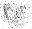
- FIG. 1 an inventive counter-rotating pin mill 10 is shown.
- This has a housing assembly 12 made of stainless steel, which consists of two housing parts 28, 30, which form a grinding chamber 17 consists.
- the first housing plate 28 has a bottom-side base plate 112 which is fixedly connected via connecting means not shown through the through holes 114 with the bottom or sub-structures not shown.
- each housing part 28, 30 coaxial with a grinding axis 13 each have a hollow grinding shaft 14, 16 is arranged.
- the grinding pins 25 may be integrally formed with the grinding discs 22, 24 or as individual grinding pins 25, for example, provided with threads in corresponding threaded holes, or by press fits in corresponding through holes in the grinding discs 22, 24 and fixedly connected are.
- the grinding shafts 14, 16 are, as in FIG. 3 can be clearly seen, each mounted in bearing blocks in bearing housings 92, 94 rotatably mounted about the grinding axis 13 and have at the respective outer ends firmly connected grinding-shaft pulleys 88, 90 on.
- the grinding-shaft-side pulleys 88, 90 are in each case operatively connected to the drives 76, 78 via drive-side pulleys 84, 86.
- the drives 76, 78 are fixedly connected to fastening means each having a housing part 28, 30. Both drives 76, 78 have control devices 96, 98, by means of which the direction of rotation and rotational speed of the respective drives 76, 78 and the associated grinding discs 22, 24 is adjustable.
- At the drive-side ends of the grinding shafts 14, 16 are fixedly connected to the bearing housings 92, 94 Mahlgutflansche 108, 110, to which Mahlgutzu Georgiavorraum not shown are connected.
- first housing part 28 has a tangential Mahlgutauslass not shown and to the grinding axis 13 coaxially arranged circular opening 116 whose diameter is greater than the diameter of the second grinding disc 24.
- the housing parts of the second housing part 30 surrounding the circular opening 116 are designed as thickened sealing surfaces 118 formed in the direction of the first housing half 28. In equal to the grinding axis 13 distances two-piece closure assemblies 120 are arranged at equal intervals.
- each closure arrangement 120 consists of a screw arrangement 122, which is designed to be rotatable parallel to the grinding axis 13, in the second housing part 30 and a corresponding thread arrangement 124, which is fixedly arranged in the first housing part 28.
- the two housing parts 28, 30 are connected via slide assemblies 32, 34 with each other.
- the slide assemblies 32, 34 each arranged in the first housing part 28 sliding bushings 40, 42, whose axes of rotation are aligned parallel to the grinding axis 13 and in which fixed to the second housing part 30 connected sliding axles 36, 38 are arranged displaceably.
- the slide assemblies 32, 34 also have rotationally symmetric and coaxial with the slide axles 36, 38 arranged damping elements 44, 46. They each have a cylindrical buffer block 48, 50 which is arranged on the drive-side end of the second housing part 30 with fastening means 52, 54 coaxial with the slide axles 36, 38.
- Hydraulically operable actuating arrangements 56, 58 are located parallel to and in each case adjacent to the slide arrangements 32, 34.
- Each actuating arrangement 56, 58 has an actuating cylinder 60, 62 which is fixedly connected to the first housing part 28 and a movable piston 64, 66 which with fastening means 72, 74 fixed to the second housing part 30 is connected.
- a hydraulic connection 68, 70 is arranged, to which a hydraulic unit, not shown, is connected.
- both housing parts 28, 30 are firmly and fluid-tightly connected to 10 bar overpressure.
- the adjusting arrangements 56, 58 hydraulically actuated locked in their minimum end positions.
- the closure assemblies 120 are also closed by the glands 122 in the respective thread assemblies 124.
- the grinding chamber 17 is supplied on both sides arranged Mahlgutzu exchangeen which are fixedly connected to the respective Mahlgutflanschen 108, 110, fed through the mutually coaxially arranged hollow grinding shafts 14, 16 regrind. This can be done in different ways.
- the transport can take place via conveying screws which extend up to the grinding chamber 17 and rotate in the grinding shafts 14, 16.
- pneumatic conveying may also make sense, in which a gaseous conveying medium is added to the material to be ground, so that the two grinding material streams meet at the center in the grinding chamber 17 at high speed.
- a gaseous conveying medium is added to the material to be ground, so that the two grinding material streams meet at the center in the grinding chamber 17 at high speed.
- the grinding discs 22, 24 are set in opposite directions in rotation. Due to the centrifugal forces acting on the material to be ground, it is finely ground between the grinding pins and, after passing through the grinding area, can be removed via the grinding material outlet, which is preferably arranged in the bottom area of the grinding space 17.
- the housing assembly 12 are opened, the shutter assemblies 120 are manually opened after switching off the drives and then with the aid of hydraulically actuated actuators 56, 58, the two housing parts 28, 30 moved apart along the grinding axis.
- the second housing part slides with the associated slide axles 36, 38 through the leading sliding bushes 40, 42 until the positioning assemblies 56, 58 have reached their maximum extended position.
- the drives 76, 78 and the Mahlgutzu®en remain firmly connected to the respective housing parts. In the now easily accessible through the circular opening 116 grinding chamber 17 cleaning and maintenance can be performed.
- the two housing parts 28, 30 can be moved together again with the aid of the adjusting arrangements 56, 58, until the sealing surface 118 of the second housing part 30 touches the opposite surface of the first housing part 28 and tightly after screwing the opposing screw assemblies 122 with the threaded assemblies 124 closes.
- the grinding process can be restarted directly.
- the cylindrical grinding pins 25 can also have a different geometric shape in order to achieve a desired grinding result.
Landscapes
- Engineering & Computer Science (AREA)
- Food Science & Technology (AREA)
- Crushing And Grinding (AREA)
- Adjustment And Processing Of Grains (AREA)
- Crushing And Pulverization Processes (AREA)
Description
- Die Erfindung bezieht sich auf eine gegenläufige Stiftmühle, insbesondere zur Vermahlung von Lebensmitteln, gemäß dem Oberbegriff des Hauptanspruchs. Stiftmühlen werden zur Vermahlung verschiedener schüttfähiger Güter eingesetzt. Dabei wird ein zu vermahlendes Gut zumeist achsnah in einen Mahlraum zwischen zwei koaxial angeordnete Mahlscheiben eingebracht. Die Mahlscheiben weisen wechselseitig in konzentrischen Kreisen angeordnete Mahlstifte auf. Das zugeführte Mahlgut wird durch die Rotation der Mahlscheibe nach außen transportiert und dabei durch die sich aneinander vorbeibewegenden Mahlstifte der beiden Mahlscheiben zerkleinert, bis die gewünschte Partikelgröße erreicht ist. Durch den Einsatz von zwei statt nur einer angetriebenen Mahlscheibe bei gegenläufigen Stiftmühlen verdoppelt sich die relative Geschwindigkeit der sich einander entgegen bewegenden Stifte, wodurch eine bessere Vermahlung erreicht wird. Gegenläufige Stiftmühlen werden oftmals zur Vermahlung von Lebensmittel genutzt. Bei der Verarbeitung von Lebensmitteln gibt es strenge gesetzliche (hygienische) Vorgaben. So ist es notwendig, den Mahlraum der Stiftmühlen regelmäßig und zumeist manuell und ohne den Einsatz von gesundheitsschädlichen Mitteln zu reinigen. Dabei ist es aufgrund des großen Durchmessers der ineinandergreifenden Mahlscheiben und der dicht aneinander rotierenden Mahlstifte nicht möglich, das Mahlgehäuse durch einen einfachen Schwenkmechanismus, bei dem eine Mahlscheibe an einem Gehäuseteil befestigt ist, zu öffnen. Die Mahlstifte würden sich berühren und würden verbiegen.
- In der
WO 93 04 780 A1 - In der
DE 28 28 029 A1 wird eine Anlage zum Vermahlen von Hopfen offenbart, die auch eine gegenläufige Stiftmühle aufweist. Diese Stiftmühle weist eine einseitig axiale Mahlgutzuführung sowie ein senkrecht zur Mahlachse in der Mahlebene zweigeteiltes Gehäuse auf. Der exakte Öffnungsmechanismus wird nicht offenbart. - In der
US 4 378 911 A wird eine Käfigmühle zur Erzvermahlung offenbart, die zweiteilig ausgebildet ist und eine im Sockel angeordnete Schienenkonstruktion sowie eine Antriebseinheit aufweist, die ein Auseinanderfahren der beiden Gehäusehälften ermöglicht. - Die
WO 2013 085 478 A1 schließlich offenbart eine Mahlvorrichtung mit zwei koaxial angeordneten hohlen Mahlwellen, durch die dem Mahlraum schüttfähiges organisches Material zugeführt wird, wobei an den inneren Enden der Mahlwellen zueinander parallele Mahlscheiben mit auf konzentrischen Kreisbahnen angeordneten Mahlgliedern angeordnet sind. Gerade bei gegenläufigen Stiftmühlen mit beidseitig axialer Zuführung ist es sehr schwierig, auf den Mahlraum zur Reinigung oder Wartung zuzugreifen, ohne zuvor und danach große Ab- und Aufrüstarbeiten durchführen zu müssen. Die Mahlgutzuführvorrichtungen und die Antriebe müssen aufwendig von den Gehäuseteilen getrennt werden. Im Stand der Technik ist keine befriedigende Lösung offenbart. - Aufgabe der Erfindung ist es, eine gegenläufige Stiftmühle, insbesondere zur Vermahlung von Lebensmitteln zu schaffen, die einfach und weit zu öffnen ist, um den Mahlraum, die Mahlwellen und die Mahlscheiben besonders einfach reinigen und warten zu können, ohne dass sich die Mahlstifte der gegenüberliegenden Mahlscheiben beim Schließen des Gehäuses berühren und dadurch verbogen werden und ohne dass die, vor allem im geöffneten Zustand durch das Gewicht des zweiten Gehäuseteils auftretenden Biegemomente ein Verkanten der beiden Gehäusehälften und der beiden Mahlscheiben bewirken.
- Diese Aufgabe wird erfindungsgemäß dadurch gelöst, dass mindestens ein Gehäuseteil längs der Mahlachse über Lagermittel verschiebbar ausgebildet ist, wobei die Lagermittel aus mindestens zwei parallel zur Mahlachse angeordneten Gleitanordnungen bestehen, die im ersten Gehäuseteil vorgesehen sind, wobei die Gleitanordnungen im ersten Gehäuseteil angeordnete Gleitbuchsen mit in diesen geführten und fest mit dem zweiten Gehäuseteil verbundene Gleitachsen aufweisen.
- Somit können die Gehäuseteile einfach auseinander gezogen werden, wobei die koaxiale Anordnung der Mahlwellen und somit auch der Mahlscheiben dabei nicht verändert werden kann. Beim Schließen des Gehäuses besteht infolgedessen nicht die Gefahr, dass sich die Mahlstifte der gegenüberliegenden Mahlscheiben berühren und dadurch verbogen werden. Zudem verbleibt durch die Nutzung von nur zwei Gleitanordnungen eine sehr gute Zugänglichkeit zu dem Mahlraum erhalten.
- Durch den Einsatz von Gleitbuchsen mit einer gewissen axialen Erstreckung können die, vor allem im geöffneten Zustand durch das Gewicht des zweiten Gehäuseteils auftretenden Biegemomente wirkungsvoll aufgenommen werden.
- In einer weiterführenden bevorzugten Ausführungsform weist die Gleitanordnungen hydraulisch angetriebene Stellanordnungen auf. Durch diese lässt sich das Gehäuse einfach öffnen und schließen, ohne manuell die schweren Gehäusehälften bewegen zu müssen.
- In einer bevorzugten Ausführungsform weist jedes Gehäuseteil einen fest damit verbundenen Antrieb auf, der über einen Antriebsriemen und über eine erste antriebsseitige Riemenscheibe und eine zweite mahlwellenseitige Riemenscheibe mit der Mahlwelle wirkverbunden ist. Diese Ausführungsform ermöglicht es, zwei unabhängige Antriebe zu nutzen, um Drehrichtung und Rotationsgeschwindigkeit dem zu vermahlenden Gut und dem gewünschten Mahlergebnis entsprechend anzupassen. Durch die Anbindung über einen Antriebsriemen ist es auf besondere Art und Weise möglich, das Mahlgut axial durch die Wellen zuzuführen.
- In einer weiterführenden bevorzugten Ausführungsform weist mindestens eine Mahlwelle an ihrem antriebsseitigen Ende eine Mahlgutzuführung auf, die über Mahlgutflansche fest mit der jeweiligen hohlen Mahlwelle verbunden ist. Durch eine dauerhaft feste Verbindung zwischen der jeweiligen Mahlgutzuführung mit dem jeweiligen Gehäuseteil kann das Gehäuse sehr einfach geöffnet werden, ohne dass die Mahlgutzuführung vom Mahlgutflansch gelöst werden muss. Zudem minimiert eine dauerhafte Verbindung zwischen den jeweiligen Mahlwellen und Antrieben den Aufwand zum Öffnen des Gehäuses.
- In einer alternativen bevorzugten Variante ist mindestens eine Mahlgutzuführung relativ bewegbar zu dem jeweiligen Gehäuseteil angeordnet. Dadurch, dass ein Teil der Mahlgutzuführung koaxial zur jeweiligen hohlen Mahlwelle in dieser axial verschiebbar angeordnet ist, können die Mahlgutzuführungen fest mit der ersten Gehäusehälfte oder dem Untergrund verbunden bleiben.
- In einer weiteren bevorzugten Ausführungsform weist die Stiftmühle Hohlräume für ein Temperiermedium auf. Durch diese kann jeweils ein erwärmendes oder ein abkühlendes Medium geleitet werden, so dass eine für das jeweilige Mahlgut optimale Verarbeitungstemperatur erreicht und gehalten werden kann.
- Es wird eine gegenläufige Stiftmühle, insbesondere zur Vermahlung von Lebensmitteln, geschaffen, die schnell und einfach weit zu öffnen ist, so dass der Mahlraum mit seinen hohlen Mahlwellen und den Mahlscheiben gut zugänglich und einfach zu reinigen ist. Nach der Reinigung ist die Stiftmühle einfach wieder zu verschließen, ohne dabei Gefahr zu laufen, durch nicht koaxiale Mahlwellen die Mahlzähne der Mahlscheiben zu beschädigen.
- Im Folgenden wird unter Bezugnahme auf die Zeichnungen die erfindungsgemäße Vorrichtung näher erläutert, es zeigen:
-
Figur 1 eine perspektivische Ansicht einer erfindungsgemäßen Stiftmühle in geöffneter Darstellung, -
Figur 2 einen senkrechten Schnitt längs der Mahlachse einer erfindungsgemäßen Stiftmühle in geöffneter Darstellung in perspektivischer Ansicht, und -
Figur 3 einen senkrechten Schnitt längs der Mahlachse 13 einer erfindungsgemäßen Stiftmühle. - In
Figur 1 ist eine erfindungsgemäße gegenläufige Stiftmühle 10 dargestellt. Diese weist eine Gehäuseanordnung 12 aus Edelstahl auf, die aus zwei Gehäuseteilen 28, 30, welche einen Mahlraum 17 bilden, besteht. Der erste Gehäusetell 28 weist eine bodenseitige Grundplatte 112 auf, die über nicht dargestellte Verbindungsmittel durch die Durchgangslöcher 114 mit dem Boden oder auch nicht dargestellten Unterkonstruktionen fest verbunden ist. In jedem Gehäuseteil 28, 30 ist koaxial zu einer Mahlachse 13 jeweils eine hohl ausgeführte Mahlwelle 14, 16 angeordnet. - Wie in der geschnittenen Ansicht in
Figur 2 besonders gut zu sehen ist, sind auf den einander zugewandten Enden 18, 20 der Mahlwellen 14, 16 zueinander parallel angeordnete Mahlscheiben 22, 24 mit wechselseitig konzentrisch angeordneten Mahlstiften 25 mit Befestigungsmitteln fixiert. Dabei können die Mahlstifte 25 einteilig mit den Mahlscheiben 22, 24 oder auch als einzelne Mahlstifte 25 ausgebildet sein, die zum Beispiel mit Gewinden versehen in korrespondierenden Gewindelöchern, oder auch durch Presspassungen in korrespondierenden Durchgangsbohrungen in den Mahlscheiben 22, 24 angeordnet und mit diesen fest verbunden sind. Die Mahlwellen 14, 16 sind, wie inFigur 3 gut zu erkennen ist, jeweils in Lagerblöcken in Lagergehäusen 92, 94 um die Mahlachse 13 drehbar gelagert angeordnet und weisen an den jeweils äußeren Enden fest verbundene mahlwellenseitige Riemenscheiben 88, 90 auf. Über Antriebsriemen 80, 82 sind die mahlwellenseitigen Riemenscheiben 88, 90 jeweils über antriebsseitige Riemenscheiben 84, 86 mit den Antrieben 76, 78 wirkverbunden. Die Antriebe 76, 78 sind mit Befestigungsmitteln fest mit jeweils einem Gehäuseteil 28, 30 verbunden. Beide Antriebe 76, 78 weisen Steuervorrichtungen 96, 98 auf, mit Hilfe derer die Rotationsrichtung und Rotationsgeschwindigkeit der jeweiligen Antriebe 76, 78 und der damit verbundenen Mahlscheiben 22, 24 einstellbar ist. An den antriebsseitigen Enden der Mahlwellen 14, 16 sind fest mit den Lagergehäusen 92, 94 verbundene Mahlgutflansche 108, 110 angeordnet, an denen nicht dargestellte Mahlgutzuführvorrichtung angeschlossen sind. Zudem weist der erste Gehäuseteil 28 einen nicht dargestellten tangentialen Mahlgutauslass und eine zur Mahlachse 13 koaxial angeordnete kreisförmige Öffnung 116 auf, deren Durchmesser größer als der Durchmesser der zweiten Mahlscheibe 24 ist. Die die kreisförmige Öffnung 116 umgebenden Gehäuseteile des zweiten Gehäuseteils 30 sind als in Richtung der ersten Gehäusehälfte 28 ausgebildete verdickte Dichtfläche 118 ausgebildet. In zur Mahlachse 13 gleichen Abständen sind zweiteilige Verschlussanordnungen 120 in gleichen Abständen zueinander angeordnet. - In der geschnittene Darstellung der
Figur 3 ist besonders gut zu erkennen, dass jede Verschlussanordnung 120 aus einer parallel zur Mahlachse 13 drehbar ausgebildeten Schraubenanordnung 122 im zweiten Gehäuseteil 30 und einer korrespondierenden Gewindeanordnung 124, die fest im ersten Gehäuseteil 28 angeordnet ist, besteht. Die beiden Gehäuseteile 28, 30 sind über Gleitanordnungen 32, 34 miteinander verbunden. Dabei weisen die Gleitanordnungen 32, 34 jeweils im ersten Gehäuseteil 28 angeordnete Gleitbuchsen 40, 42 auf, deren Rotationsachsen parallel zur Mahlachse 13 ausgerichtet sind und in denen fest mit dem zweiten Gehäuseteil 30 verbundene Gleitachsen 36, 38 verschiebbar angeordnet sind. Die Gleitanordnungen 32, 34 weisen zudem rotationssymmetrische und koaxial zu den Gleitachsen 36, 38 angeordnete Dämpfungselemente 44, 46 auf. Sie weisen jeweils einen zylinderförmigen Pufferblock 48, 50 auf, der auf dem antriebsseitigen Ende des zweiten Gehäuseteils 30 mit Befestigungsmittel 52, 54 koaxial zu den Gleitachsen 36, 38 angeordnet ist. Parallel zu und jeweils neben den Gleitanordnungen 32, 34 befinden sich hydraulisch betätigbare Stellanordnungen 56, 58. Jede Stellanordnung 56, 58 weist einen Stellzylinder 60, 62, der mit dem ersten Gehäuseteil 28 fest verbunden ist, und einen bewegbaren Kolben 64, 66, der mit Befestigungsmitteln 72, 74 mit dem zweiten Gehäuseteil 30 fest verbunden ist, auf. Zudem ist am äußeren Ende des Stellzylinders 60, 62 ein Hydraulikanschluss 68, 70 angeordnet, an den eine nicht dargestellte Hydraulikeinheit angeschlossen ist. - Im regulären Arbeitsbetrieb einer erfindungsgemäßen Stiftmühle 10 sind beide Gehäuseteile 28, 30 fest und fluiddicht bis 10 bar Überdruck verbunden. Dazu sind die Stellanordnungen 56, 58 hydraulisch aktuiert in ihren minimalen Endstellungen arretiert. Die Verschlussanordnungen 120 sind zudem durch die Verschraubungen 122 in den jeweiligen Gewindeanordnungen 124 geschlossen. Dem Mahlraum 17 wird über beidseitig angeordnete Mahlgutzuführungen, welche fest mit den jeweiligen Mahlgutflanschen 108, 110 verbunden sind, durch die einander gegenüber koaxial angeordneten hohlen Mahlwellen 14, 16 Mahlgut zugeführt. Dieses kann auf verschiedene Arten erfolgen. So kann bei feuchtem oder klebrigen Gut der Transport über bis an den Mahlraum 17 reichende, in den Mahlwellen 14, 16 rotierende Förderschnecken erfolgen. Alternativ kann auch eine pneumatische Förderung Sinn ergeben, bei der dem Mahlgut ein gasförmiges Fördermedium hinzugefügt wird, so dass die beiden Mahlgutströme mittig im Mahlraum 17 mit großer Geschwindigkeit aufeinander treffen. Dadurch wird schon bei der Mahlgutzuführung eine Vorzerkleinerung der zu vermahlenden Stoffe erreicht.
- Durch die von den Antrieben 76, 78 über die antriebsseitigen Riemenscheiben 84, 86, die Antriebsriemen 80, 82 und die mahlwellenseitigen Riemenscheiben 88, 90 in Rotation gebrachten Mahlwellen 14, 16, werden die Mahlscheiben 22, 24 gegenläufig in Rotation versetzt. Durch die auf das Mahlgut wirkenden Fliehkräfte wird dieses zwischen den Mahlstiften fein vermahlen und kann nach Durchtritt durch den Mahlbereich über den, bevorzugt im Bodenbereich des Mahlraums 17 angeordneten Mahlgutauslass, abgeführt werden.
- Muss nun, zum Beispiel zur regelmäßigen Reinigung des Mahlraums 17 oder zum Wechsel von einzelnen Mahlstiften 25, die Gehäuseanordnung 12 geöffnet werden, werden nach Abschaltung der Antriebe zuerst die Verschlussanordnungen 120 manuell geöffnet und danach mit Hilfe der hydraulisch aktuierten Stellanordnungen 56, 58 die beiden Gehäuseteile 28, 30 längs der Mahlachse auseinander gefahren. Dabei gleitet der zweite Gehäuseteil mit den verbundenen Gleitachsen 36, 38 durch die führenden Gleitbuchsen 40, 42, bis die Stellanordnungen 56, 58 ihre maximal ausgefahrene Position erreicht haben. Dabei bleiben die Antriebe 76, 78 und auch die Mahlgutzuführungen fest mit den jeweiligen Gehäuseteilen verbunden. In dem nun durch die kreisförmige Öffnung 116 leicht zugänglichen Mahlraum 17 können Reinigungs- und Wartungsarbeiten durchgeführt werden. Nach deren Beendigung können die beiden Gehäuseteile 28, 30 wieder mit Hilfe der Stellanordnungen 56, 58 zusammengefahren werden, bis die Dichtfläche 118 des zweiten Gehäuseteils 30 die gegenüberliegende Fläche des ersten Gehäuseteils 28 berührt und nach Verschraubung der einander gegenüberliegenden Schraubenanordnungen 122 mit den Gewindeanordnungen 124 dicht verschließt. Der Mahlvorgang kann direkt wieder gestartet werden.
- Es sollte deutlich sein, dass der Schutzbereich der vorliegenden Anmeldung nicht auf das beschriebene Ausführungsbeispiel beschränkt ist. Insbesondere können statt der hydraulisch angetriebenen Stellanordnungen 56, 58 auch pneumatisch oder elektrisch angetriebene Stellanordnungen 56, 58 genutzt werden. Auch eine rein manuelle Trennung der beiden Gehäuseteile 28, 30 ist denkbar.
- Um das Mahlgut bei einer bestimmten Temperatur zu vermahlen, ist es zudem denkbar, über zirkulierende Medien, wie zum Beispiel Stickstoff, in Hohlräumen der Mahlscheiben 22, 24 diese zu erwärmen oder abzukühlen und dadurch auf die Vermahlungstemperatur Einfluss zu nehmen.
- Auch denkbar wäre es, die Gehäuseanordnung 12 so zu gestalten, dass die Dichtfläche 118 der beiden Gehäuseteile 28, 30 in der Mahlebene angeordnet ist.
- Die zylinderförmigen Mahlstifte 25 können zudem auch eine andere geometrische Form aufweisen, um ein gewünschtes Mahlergebnis zu erreichen.
Claims (7)
- Gegenläufige Stiftmühle (10), insbesondere zur Vermahlung von Lebensmitteln, bestehend aus
einer Gehäuseanordnung (12) mit zumindest einem ersten und einem zweiten Gehäuseteil (28, 30),
zwei darin koaxial zueinander auf einer Mahlachse (13) angeordneten Mahlwellen (14, 16), von denen mindestens eine Mahlwelle (14, 16) einen Mahlguteinlass aufweist und hohl ausgeführt ist, durch die einem Mahlraum (17) Mahlgut zuführbar ist,
zwei auf den einander zugewandten Enden (18, 20) der Mahlwellen (14, 16) zueinander parallel angeordneten Mahlscheiben (22, 24), einem Mahlgutauslass, durch den aus dem Mahlraum (17) Mahlgut abführbar ist,
dadurch gekennzeichnet, dass
mindestens ein Gehäuseteil (28, 30) längs der Mahlachse (13) über Lagermittel verschiebbar ausgebildet ist,
wobei die Lagermittel aus mindestens zwei parallel zur Mahlachse (13) angeordneten Gleitanordnungen (32, 34) bestehen, die im ersten Gehäuseteil (28) vorgesehen sind,
wobei die Gleitanordnungen (32, 34) im ersten Gehäuseteil (28) angeordnete Gleitbuchsen (40, 42) mit in diesen geführten und fest mit dem zweiten Gehäuseteil (30) verbundene Gleitachsen (36, 38) aufweisen. - Stiftmühle (10) nach Anspruch 1,
dadurch gekennzeichnet, dass
die Gleitanordnungen (32, 34) hydraulisch angetriebene Stellanordnungen (56, 58) aufweisen. - Stiftmühle (10) nach einem der vorhergehenden Ansprüche,
dadurch gekennzeichnet, dass
jedes Gehäuseteil (28, 30) einen fest damit verbundenen Antrieb (76, 78) aufweist, der über einen Antriebsriemen (80, 82) und über eine erste antriebsseitige Riemenscheibe (84, 86) und eine zweite mahlwellenseitige Riemenscheibe (88, 90) mit der Mahlwelle (14, 16) wirkverbunden ist. - Stiftmühle (10) nach einem der vorhergehenden Ansprüche,
dadurch gekennzeichnet, dass
mindestens eine Mahlwelle (14, 16) an ihrem antriebsseitigen Ende eine Mahlgutzuführung aufweist, die über Mahlgutflansche (108, 110) mit der Mahlwelle (14, 16) verbunden ist. - Stiftmühle (10) nach Anspruch 4,
dadurch gekennzeichnet, dass
die Mahlgutzuführung fest mit dem jeweiligen Gehäuseteil (28, 30) verbunden ist, so dass keine Relativbewegung zwischen der Mahlgutzuführung und dem jeweiligen Gehäuseteil (28, 30) möglich ist. - Stiftmühle (10) nach Anspruch 4,
dadurch gekennzeichnet, dass
die Mahlgutzuführung relativ bewegbar zu dem jeweiligen Gehäuseteil (28) angeordnet ist. - Stiftmühle (10) nach einem der vorhergehenden Ansprüche,
dadurch gekennzeichnet, dass
die Gehäuseanordnung (12) Hohlräume für ein Temperiermedium aufweist.
Applications Claiming Priority (2)
| Application Number | Priority Date | Filing Date | Title |
|---|---|---|---|
| DE102014101786.2A DE102014101786B4 (de) | 2014-02-13 | 2014-02-13 | Gegenläufige Stiftmühle |
| PCT/EP2015/050542 WO2015121012A1 (de) | 2014-02-13 | 2015-01-14 | Gegenläufige stiftmühle |
Publications (2)
| Publication Number | Publication Date |
|---|---|
| EP3104977A1 EP3104977A1 (de) | 2016-12-21 |
| EP3104977B1 true EP3104977B1 (de) | 2017-11-29 |
Family
ID=52358773
Family Applications (1)
| Application Number | Title | Priority Date | Filing Date |
|---|---|---|---|
| EP15700564.6A Active EP3104977B1 (de) | 2014-02-13 | 2015-01-14 | Gegenläufige stiftmühle |
Country Status (7)
| Country | Link |
|---|---|
| US (1) | US10413907B2 (de) |
| EP (1) | EP3104977B1 (de) |
| CN (1) | CN206351062U (de) |
| DE (1) | DE102014101786B4 (de) |
| TR (1) | TR201802798T4 (de) |
| TW (1) | TWI654028B (de) |
| WO (1) | WO2015121012A1 (de) |
Families Citing this family (3)
| Publication number | Priority date | Publication date | Assignee | Title |
|---|---|---|---|---|
| DE102017010910A1 (de) | 2017-11-23 | 2019-05-23 | Technische Universität Bergakademie Freiberg | Stiftmühle mit Scheiben mit Stiften |
| US12103868B2 (en) | 2021-01-27 | 2024-10-01 | Shockwater Solutions, LLC | Process and apparatus for multi-phase reaction processing of liquids |
| CN120906908B (zh) * | 2025-10-11 | 2025-12-09 | 爱安特(常州)精密机械有限公司 | 一种高强度轴承座 |
Family Cites Families (20)
| Publication number | Priority date | Publication date | Assignee | Title |
|---|---|---|---|---|
| US2502022A (en) * | 1944-05-01 | 1950-03-28 | Christian F Paul | Opposed disk rotor type centrifugal pulverizer |
| US2539775A (en) * | 1947-06-07 | 1951-01-30 | Comb Eng Superheater Inc | Quick opening cage mill |
| US2623700A (en) * | 1949-02-21 | 1952-12-30 | Scherer Corp R P | Disintegrating device |
| AT356045B (de) | 1978-05-11 | 1980-04-10 | Simmering Graz Pauker Ag | Verfahren und vorrichtung zur vorentlaugung von hopfen |
| AT362290B (de) * | 1978-06-26 | 1981-04-27 | Simmering Graz Pauker Ag | Verfahren zur regenerierung und reaktivierung inaktiv gewordenen zementes |
| US4226375A (en) * | 1978-12-21 | 1980-10-07 | Copper Alloys Corp. | Reduction mill |
| US4366929A (en) * | 1980-05-01 | 1983-01-04 | Los Santos Federico De | Process and apparatus for grinding materials |
| US4378911A (en) * | 1980-07-03 | 1983-04-05 | Wean United, Inc. | Cage mill |
| NL8303825A (nl) * | 1982-11-20 | 1984-06-18 | Nickel Heinrich | Inrichting voor het door stootwerking verkleinen van te malen materiaal. |
| SU1306596A1 (ru) * | 1984-12-21 | 1987-04-30 | Специальное Конструкторско-Технологическое Бюро "Дезинтегратор" | Дезинтегратор |
| DE3644448C1 (de) * | 1986-12-24 | 1988-06-01 | Kasa Technoplan | Antriebs- und Lageranordnung fuer zwei gegensinnig und nebeneinander umlaufende Rotorsysteme |
| EP0296791A3 (de) * | 1987-06-22 | 1990-03-28 | Design Count Pty. Ltd. | Verfahren und Vorrichtung zum Abtrennen von Nichteisen-Metallen aus elektrischen Kabeln |
| CH684576A5 (de) | 1991-08-30 | 1994-10-31 | Tradepoint Handelsgesellschaft | Mahlverfahren und Anlage zu dessen Ausführung. |
| US5580009A (en) * | 1994-11-17 | 1996-12-03 | Kennedy; Joseph | Solid waste comminutor |
| JP3451483B2 (ja) | 2000-05-30 | 2003-09-29 | 伸和工業株式会社 | 粉砕機 |
| JP4452046B2 (ja) | 2003-08-26 | 2010-04-21 | ツカサ工業株式会社 | ミル |
| DE112005003854B4 (de) * | 2004-06-23 | 2018-04-26 | Masataka Tamura | Brechvorrichtung |
| TWM273392U (en) | 2004-12-20 | 2005-08-21 | Ta Ti Hsing Machinery Co Ltd | Improved structure of wet and dry two-purpose bean grinder |
| DE102005045273A1 (de) * | 2005-09-22 | 2007-03-29 | Khd Humboldt Wedag Gmbh | Zweiwalzenmaschine insbesondere zur Gutbettzerkleinerung |
| WO2013085478A1 (en) * | 2011-12-05 | 2013-06-13 | Bunetsky Vladimir | Grinding work member and centrifugal disintegrator based thereon |
-
2014
- 2014-02-13 DE DE102014101786.2A patent/DE102014101786B4/de not_active Expired - Fee Related
-
2015
- 2015-01-14 TR TR2018/02798T patent/TR201802798T4/tr unknown
- 2015-01-14 WO PCT/EP2015/050542 patent/WO2015121012A1/de not_active Ceased
- 2015-01-14 CN CN201590000260.7U patent/CN206351062U/zh not_active Expired - Fee Related
- 2015-01-14 EP EP15700564.6A patent/EP3104977B1/de active Active
- 2015-01-14 US US15/115,696 patent/US10413907B2/en active Active
- 2015-01-30 TW TW104103159A patent/TWI654028B/zh not_active IP Right Cessation
Also Published As
| Publication number | Publication date |
|---|---|
| US10413907B2 (en) | 2019-09-17 |
| DE102014101786A1 (de) | 2015-08-13 |
| DE102014101786B4 (de) | 2016-12-22 |
| EP3104977A1 (de) | 2016-12-21 |
| TR201802798T4 (tr) | 2018-03-21 |
| TW201536412A (zh) | 2015-10-01 |
| US20170165675A1 (en) | 2017-06-15 |
| CN206351062U (zh) | 2017-07-25 |
| WO2015121012A1 (de) | 2015-08-20 |
| TWI654028B (zh) | 2019-03-21 |
Similar Documents
| Publication | Publication Date | Title |
|---|---|---|
| DE2550969C2 (de) | Schneckenmaschine zum Homogenisieren von festen, flüssigen und zähviskosen Materialien | |
| CH708196A2 (de) | Kaffeemühle, insbesondere für eine automatische Kaffeemaschine. | |
| DE60208700T2 (de) | Schälgerät und zugehörige verfahren | |
| DE102014101786B4 (de) | Gegenläufige Stiftmühle | |
| DE19603627A1 (de) | Wirbelstrommühle | |
| DE19508093A1 (de) | Fleischwolf | |
| DE10026825C2 (de) | Zerkleinerungsvorrichtung | |
| CH604896A5 (en) | Double parallel cutter refuse grinding machine | |
| DE102015106458B4 (de) | Zellenradschleuse | |
| EP1210178B1 (de) | Zerkleinerungsmaschine | |
| DE3823718A1 (de) | Vorrichtung zum begrenzen und justieren des schaltweges bei armaturen | |
| EP3808517B1 (de) | Eine schneidvorrichtung, insbesondere eine rotationsablängmaschine für werkstücke aus der kunststoff- und/oder gummiextrusion | |
| EP1914185A1 (de) | Vorrichtung zur Behandlung einer Warenbahn | |
| EP2396257B1 (de) | Verstellvorrichtung zur verwendung bei einem transporteur | |
| DE202009017684U1 (de) | Zerkleinerungsvorrichtung für Schüttgutpartikel | |
| DE1804744A1 (de) | Mahlwerk | |
| DE370321C (de) | Beschickungsvorrichtung fuer pulverfoermige Brennstoffe | |
| DE19645097A1 (de) | Zellenradschleuse mit schnellwechselbarer Dichtungsanordnung | |
| DE2253824C3 (de) | ||
| DE202025101938U1 (de) | Schneideinrichtung, insbesondere für Feinstzerkleinerer, Konti-Feinstzerkleinerer, Kutter und dgl. | |
| EP0159710A2 (de) | Verfahren und Vorrichtung zur Mahlung von schwermahlbarem Gut, insbesondere von feuchter Kohle oder Koks | |
| DE9400427U1 (de) | Walzenschrotpresse | |
| DE102010028048B4 (de) | Vorrichtung zur Zerkleinerung und Klassierung | |
| DE202008000154U1 (de) | Zerkleinerungsvorrichtung für Schüttgutpartikel | |
| EP2505525B1 (de) | Welle zur Verwendung in Antriebs- und Transportvorrichtungen |
Legal Events
| Date | Code | Title | Description |
|---|---|---|---|
| PUAI | Public reference made under article 153(3) epc to a published international application that has entered the european phase |
Free format text: ORIGINAL CODE: 0009012 |
|
| STAA | Information on the status of an ep patent application or granted ep patent |
Free format text: STATUS: REQUEST FOR EXAMINATION WAS MADE |
|
| 17P | Request for examination filed |
Effective date: 20160726 |
|
| AK | Designated contracting states |
Kind code of ref document: A1 Designated state(s): AL AT BE BG CH CY CZ DE DK EE ES FI FR GB GR HR HU IE IS IT LI LT LU LV MC MK MT NL NO PL PT RO RS SE SI SK SM TR |
|
| AX | Request for extension of the european patent |
Extension state: BA ME |
|
| DAX | Request for extension of the european patent (deleted) | ||
| GRAP | Despatch of communication of intention to grant a patent |
Free format text: ORIGINAL CODE: EPIDOSNIGR1 |
|
| STAA | Information on the status of an ep patent application or granted ep patent |
Free format text: STATUS: GRANT OF PATENT IS INTENDED |
|
| INTG | Intention to grant announced |
Effective date: 20170726 |
|
| GRAS | Grant fee paid |
Free format text: ORIGINAL CODE: EPIDOSNIGR3 |
|
| GRAA | (expected) grant |
Free format text: ORIGINAL CODE: 0009210 |
|
| STAA | Information on the status of an ep patent application or granted ep patent |
Free format text: STATUS: THE PATENT HAS BEEN GRANTED |
|
| AK | Designated contracting states |
Kind code of ref document: B1 Designated state(s): AL AT BE BG CH CY CZ DE DK EE ES FI FR GB GR HR HU IE IS IT LI LT LU LV MC MK MT NL NO PL PT RO RS SE SI SK SM TR |
|
| REG | Reference to a national code |
Ref country code: CH Ref legal event code: EP |
|
| REG | Reference to a national code |
Ref country code: AT Ref legal event code: REF Ref document number: 949895 Country of ref document: AT Kind code of ref document: T Effective date: 20171215 |
|
| REG | Reference to a national code |
Ref country code: IE Ref legal event code: FG4D Free format text: LANGUAGE OF EP DOCUMENT: GERMAN |
|
| REG | Reference to a national code |
Ref country code: DE Ref legal event code: R096 Ref document number: 502015002448 Country of ref document: DE |
|
| REG | Reference to a national code |
Ref country code: NL Ref legal event code: FP |
|
| REG | Reference to a national code |
Ref country code: FR Ref legal event code: PLFP Year of fee payment: 4 |
|
| REG | Reference to a national code |
Ref country code: GB Ref legal event code: 732E Free format text: REGISTERED BETWEEN 20180308 AND 20180314 |
|
| REG | Reference to a national code |
Ref country code: LT Ref legal event code: MG4D |
|
| REG | Reference to a national code |
Ref country code: DE Ref legal event code: R082 Ref document number: 502015002448 Country of ref document: DE Representative=s name: TERPATENT PATENTANWAELTE TER SMITTEN EBERLEIN-, DE Ref country code: DE Ref legal event code: R082 Ref document number: 502015002448 Country of ref document: DE Representative=s name: PATENTANWAELTE TER SMITTEN EBERLEIN-VAN HOOF R, DE Ref country code: DE Ref legal event code: R081 Ref document number: 502015002448 Country of ref document: DE Owner name: HAMBURG DRESDNER MASCHINENFABRIKEN VERWALTUNGS, DE Free format text: FORMER OWNER: HAMBURG DRESDNER MASCHINENFABRIKEN GMBH, 01239 DRESDEN, DE |
|
| RAP2 | Party data changed (patent owner data changed or rights of a patent transferred) |
Owner name: HAMBURG DRESDNER MASCHINENFABRIKEN VERWALTUNGSGESE |
|
| PG25 | Lapsed in a contracting state [announced via postgrant information from national office to epo] |
Ref country code: ES Free format text: LAPSE BECAUSE OF FAILURE TO SUBMIT A TRANSLATION OF THE DESCRIPTION OR TO PAY THE FEE WITHIN THE PRESCRIBED TIME-LIMIT Effective date: 20171129 Ref country code: LT Free format text: LAPSE BECAUSE OF FAILURE TO SUBMIT A TRANSLATION OF THE DESCRIPTION OR TO PAY THE FEE WITHIN THE PRESCRIBED TIME-LIMIT Effective date: 20171129 Ref country code: FI Free format text: LAPSE BECAUSE OF FAILURE TO SUBMIT A TRANSLATION OF THE DESCRIPTION OR TO PAY THE FEE WITHIN THE PRESCRIBED TIME-LIMIT Effective date: 20171129 Ref country code: SE Free format text: LAPSE BECAUSE OF FAILURE TO SUBMIT A TRANSLATION OF THE DESCRIPTION OR TO PAY THE FEE WITHIN THE PRESCRIBED TIME-LIMIT Effective date: 20171129 Ref country code: NO Free format text: LAPSE BECAUSE OF FAILURE TO SUBMIT A TRANSLATION OF THE DESCRIPTION OR TO PAY THE FEE WITHIN THE PRESCRIBED TIME-LIMIT Effective date: 20180228 |
|
| PG25 | Lapsed in a contracting state [announced via postgrant information from national office to epo] |
Ref country code: GR Free format text: LAPSE BECAUSE OF FAILURE TO SUBMIT A TRANSLATION OF THE DESCRIPTION OR TO PAY THE FEE WITHIN THE PRESCRIBED TIME-LIMIT Effective date: 20180301 Ref country code: RS Free format text: LAPSE BECAUSE OF FAILURE TO SUBMIT A TRANSLATION OF THE DESCRIPTION OR TO PAY THE FEE WITHIN THE PRESCRIBED TIME-LIMIT Effective date: 20171129 Ref country code: LV Free format text: LAPSE BECAUSE OF FAILURE TO SUBMIT A TRANSLATION OF THE DESCRIPTION OR TO PAY THE FEE WITHIN THE PRESCRIBED TIME-LIMIT Effective date: 20171129 Ref country code: HR Free format text: LAPSE BECAUSE OF FAILURE TO SUBMIT A TRANSLATION OF THE DESCRIPTION OR TO PAY THE FEE WITHIN THE PRESCRIBED TIME-LIMIT Effective date: 20171129 Ref country code: BG Free format text: LAPSE BECAUSE OF FAILURE TO SUBMIT A TRANSLATION OF THE DESCRIPTION OR TO PAY THE FEE WITHIN THE PRESCRIBED TIME-LIMIT Effective date: 20180228 |
|
| REG | Reference to a national code |
Ref country code: CH Ref legal event code: PUE Owner name: HAMBURG DRESDNER MASCHINENFABRIKEN VERWALTUNGS, DE Free format text: FORMER OWNER: HAMBURG DRESDNER MASCHINENFABRIKEN GMBH, DE Ref country code: CH Ref legal event code: PK Free format text: BERICHTIGUNG INHABER Ref country code: CH Ref legal event code: NV Representative=s name: GEVERS SA, CH |
|
| PG25 | Lapsed in a contracting state [announced via postgrant information from national office to epo] |
Ref country code: CZ Free format text: LAPSE BECAUSE OF FAILURE TO SUBMIT A TRANSLATION OF THE DESCRIPTION OR TO PAY THE FEE WITHIN THE PRESCRIBED TIME-LIMIT Effective date: 20171129 Ref country code: EE Free format text: LAPSE BECAUSE OF FAILURE TO SUBMIT A TRANSLATION OF THE DESCRIPTION OR TO PAY THE FEE WITHIN THE PRESCRIBED TIME-LIMIT Effective date: 20171129 Ref country code: DK Free format text: LAPSE BECAUSE OF FAILURE TO SUBMIT A TRANSLATION OF THE DESCRIPTION OR TO PAY THE FEE WITHIN THE PRESCRIBED TIME-LIMIT Effective date: 20171129 Ref country code: SK Free format text: LAPSE BECAUSE OF FAILURE TO SUBMIT A TRANSLATION OF THE DESCRIPTION OR TO PAY THE FEE WITHIN THE PRESCRIBED TIME-LIMIT Effective date: 20171129 Ref country code: CY Free format text: LAPSE BECAUSE OF FAILURE TO SUBMIT A TRANSLATION OF THE DESCRIPTION OR TO PAY THE FEE WITHIN THE PRESCRIBED TIME-LIMIT Effective date: 20171129 |
|
| REG | Reference to a national code |
Ref country code: NL Ref legal event code: PD Owner name: HAMBURG DRESDNER MASCHINENFABRIKEN VERWALTUNGSGESE Free format text: DETAILS ASSIGNMENT: CHANGE OF OWNER(S), ASSIGNMENT; FORMER OWNER NAME: HAMBURG DRESDNER MASCHINENFABRIKEN GMBH Effective date: 20180608 |
|
| REG | Reference to a national code |
Ref country code: DE Ref legal event code: R097 Ref document number: 502015002448 Country of ref document: DE |
|
| PG25 | Lapsed in a contracting state [announced via postgrant information from national office to epo] |
Ref country code: PL Free format text: LAPSE BECAUSE OF FAILURE TO SUBMIT A TRANSLATION OF THE DESCRIPTION OR TO PAY THE FEE WITHIN THE PRESCRIBED TIME-LIMIT Effective date: 20171129 Ref country code: SM Free format text: LAPSE BECAUSE OF FAILURE TO SUBMIT A TRANSLATION OF THE DESCRIPTION OR TO PAY THE FEE WITHIN THE PRESCRIBED TIME-LIMIT Effective date: 20171129 |
|
| PG25 | Lapsed in a contracting state [announced via postgrant information from national office to epo] |
Ref country code: MT Free format text: LAPSE BECAUSE OF FAILURE TO SUBMIT A TRANSLATION OF THE DESCRIPTION OR TO PAY THE FEE WITHIN THE PRESCRIBED TIME-LIMIT Effective date: 20171129 |
|
| PLBE | No opposition filed within time limit |
Free format text: ORIGINAL CODE: 0009261 |
|
| STAA | Information on the status of an ep patent application or granted ep patent |
Free format text: STATUS: NO OPPOSITION FILED WITHIN TIME LIMIT |
|
| PG25 | Lapsed in a contracting state [announced via postgrant information from national office to epo] |
Ref country code: LU Free format text: LAPSE BECAUSE OF NON-PAYMENT OF DUE FEES Effective date: 20180114 |
|
| REG | Reference to a national code |
Ref country code: IE Ref legal event code: MM4A |
|
| 26N | No opposition filed |
Effective date: 20180830 |
|
| REG | Reference to a national code |
Ref country code: BE Ref legal event code: MM Effective date: 20180131 |
|
| PG25 | Lapsed in a contracting state [announced via postgrant information from national office to epo] |
Ref country code: SI Free format text: LAPSE BECAUSE OF FAILURE TO SUBMIT A TRANSLATION OF THE DESCRIPTION OR TO PAY THE FEE WITHIN THE PRESCRIBED TIME-LIMIT Effective date: 20171129 Ref country code: BE Free format text: LAPSE BECAUSE OF NON-PAYMENT OF DUE FEES Effective date: 20180131 |
|
| PG25 | Lapsed in a contracting state [announced via postgrant information from national office to epo] |
Ref country code: IE Free format text: LAPSE BECAUSE OF NON-PAYMENT OF DUE FEES Effective date: 20180114 |
|
| REG | Reference to a national code |
Ref country code: CH Ref legal event code: NV Representative=s name: BOVARD SA NEUCHATEL CONSEILS EN PROPRIETE INTE, CH |
|
| PG25 | Lapsed in a contracting state [announced via postgrant information from national office to epo] |
Ref country code: MC Free format text: LAPSE BECAUSE OF FAILURE TO SUBMIT A TRANSLATION OF THE DESCRIPTION OR TO PAY THE FEE WITHIN THE PRESCRIBED TIME-LIMIT Effective date: 20171129 |
|
| REG | Reference to a national code |
Ref country code: DE Ref legal event code: R082 Ref document number: 502015002448 Country of ref document: DE Representative=s name: TERPATENT PARTGMBB, DE Ref country code: DE Ref legal event code: R082 Ref document number: 502015002448 Country of ref document: DE Representative=s name: TERPATENT PATENTANWAELTE TER SMITTEN EBERLEIN-, DE |
|
| PGFP | Annual fee paid to national office [announced via postgrant information from national office to epo] |
Ref country code: GB Payment date: 20200127 Year of fee payment: 6 |
|
| PG25 | Lapsed in a contracting state [announced via postgrant information from national office to epo] |
Ref country code: PT Free format text: LAPSE BECAUSE OF FAILURE TO SUBMIT A TRANSLATION OF THE DESCRIPTION OR TO PAY THE FEE WITHIN THE PRESCRIBED TIME-LIMIT Effective date: 20171129 |
|
| PG25 | Lapsed in a contracting state [announced via postgrant information from national office to epo] |
Ref country code: MK Free format text: LAPSE BECAUSE OF NON-PAYMENT OF DUE FEES Effective date: 20171129 Ref country code: RO Free format text: LAPSE BECAUSE OF FAILURE TO SUBMIT A TRANSLATION OF THE DESCRIPTION OR TO PAY THE FEE WITHIN THE PRESCRIBED TIME-LIMIT Effective date: 20171129 Ref country code: HU Free format text: LAPSE BECAUSE OF FAILURE TO SUBMIT A TRANSLATION OF THE DESCRIPTION OR TO PAY THE FEE WITHIN THE PRESCRIBED TIME-LIMIT; INVALID AB INITIO Effective date: 20150114 |
|
| PGFP | Annual fee paid to national office [announced via postgrant information from national office to epo] |
Ref country code: TR Payment date: 20200109 Year of fee payment: 6 Ref country code: FR Payment date: 20200123 Year of fee payment: 6 |
|
| PG25 | Lapsed in a contracting state [announced via postgrant information from national office to epo] |
Ref country code: IS Free format text: LAPSE BECAUSE OF FAILURE TO SUBMIT A TRANSLATION OF THE DESCRIPTION OR TO PAY THE FEE WITHIN THE PRESCRIBED TIME-LIMIT Effective date: 20180329 Ref country code: AL Free format text: LAPSE BECAUSE OF FAILURE TO SUBMIT A TRANSLATION OF THE DESCRIPTION OR TO PAY THE FEE WITHIN THE PRESCRIBED TIME-LIMIT Effective date: 20171129 |
|
| REG | Reference to a national code |
Ref country code: AT Ref legal event code: MM01 Ref document number: 949895 Country of ref document: AT Kind code of ref document: T Effective date: 20200114 |
|
| PG25 | Lapsed in a contracting state [announced via postgrant information from national office to epo] |
Ref country code: AT Free format text: LAPSE BECAUSE OF NON-PAYMENT OF DUE FEES Effective date: 20200114 |
|
| GBPC | Gb: european patent ceased through non-payment of renewal fee |
Effective date: 20210114 |
|
| PG25 | Lapsed in a contracting state [announced via postgrant information from national office to epo] |
Ref country code: FR Free format text: LAPSE BECAUSE OF NON-PAYMENT OF DUE FEES Effective date: 20210131 |
|
| PG25 | Lapsed in a contracting state [announced via postgrant information from national office to epo] |
Ref country code: GB Free format text: LAPSE BECAUSE OF NON-PAYMENT OF DUE FEES Effective date: 20210114 |
|
| PGFP | Annual fee paid to national office [announced via postgrant information from national office to epo] |
Ref country code: CH Payment date: 20230130 Year of fee payment: 9 |
|
| PGFP | Annual fee paid to national office [announced via postgrant information from national office to epo] |
Ref country code: IT Payment date: 20230131 Year of fee payment: 9 Ref country code: DE Payment date: 20230119 Year of fee payment: 9 |
|
| PGFP | Annual fee paid to national office [announced via postgrant information from national office to epo] |
Ref country code: NL Payment date: 20230124 Year of fee payment: 9 |
|
| P01 | Opt-out of the competence of the unified patent court (upc) registered |
Effective date: 20230530 |
|
| P02 | Opt-out of the competence of the unified patent court (upc) changed |
Effective date: 20230530 |
|
| REG | Reference to a national code |
Ref country code: DE Ref legal event code: R119 Ref document number: 502015002448 Country of ref document: DE |
|
| REG | Reference to a national code |
Ref country code: CH Ref legal event code: PL |
|
| REG | Reference to a national code |
Ref country code: NL Ref legal event code: MM Effective date: 20240201 |
|
| PG25 | Lapsed in a contracting state [announced via postgrant information from national office to epo] |
Ref country code: DE Free format text: LAPSE BECAUSE OF NON-PAYMENT OF DUE FEES Effective date: 20240801 |
|
| PG25 | Lapsed in a contracting state [announced via postgrant information from national office to epo] |
Ref country code: NL Free format text: LAPSE BECAUSE OF NON-PAYMENT OF DUE FEES Effective date: 20240201 |
|
| PG25 | Lapsed in a contracting state [announced via postgrant information from national office to epo] |
Ref country code: CH Free format text: LAPSE BECAUSE OF NON-PAYMENT OF DUE FEES Effective date: 20240131 |
|
| PG25 | Lapsed in a contracting state [announced via postgrant information from national office to epo] |
Ref country code: NL Free format text: LAPSE BECAUSE OF NON-PAYMENT OF DUE FEES Effective date: 20240201 Ref country code: DE Free format text: LAPSE BECAUSE OF NON-PAYMENT OF DUE FEES Effective date: 20240801 Ref country code: CH Free format text: LAPSE BECAUSE OF NON-PAYMENT OF DUE FEES Effective date: 20240131 |
|
| PG25 | Lapsed in a contracting state [announced via postgrant information from national office to epo] |
Ref country code: IT Free format text: LAPSE BECAUSE OF NON-PAYMENT OF DUE FEES Effective date: 20240114 |