EP3104992B1 - Machine et procédé de forgeage - Google Patents
Machine et procédé de forgeage Download PDFInfo
- Publication number
- EP3104992B1 EP3104992B1 EP15711830.8A EP15711830A EP3104992B1 EP 3104992 B1 EP3104992 B1 EP 3104992B1 EP 15711830 A EP15711830 A EP 15711830A EP 3104992 B1 EP3104992 B1 EP 3104992B1
- Authority
- EP
- European Patent Office
- Prior art keywords
- piston
- connecting rod
- wedge
- machine
- hammer
- Prior art date
- Legal status (The legal status is an assumption and is not a legal conclusion. Google has not performed a legal analysis and makes no representation as to the accuracy of the status listed.)
- Active
Links
Images
Classifications
-
- B—PERFORMING OPERATIONS; TRANSPORTING
- B21—MECHANICAL METAL-WORKING WITHOUT ESSENTIALLY REMOVING MATERIAL; PUNCHING METAL
- B21J—FORGING; HAMMERING; PRESSING METAL; RIVETING; FORGE FURNACES
- B21J7/00—Hammers; Forging machines with hammers or die jaws acting by impact
- B21J7/02—Special design or construction
- B21J7/14—Forging machines working with several hammers
-
- B—PERFORMING OPERATIONS; TRANSPORTING
- B21—MECHANICAL METAL-WORKING WITHOUT ESSENTIALLY REMOVING MATERIAL; PUNCHING METAL
- B21J—FORGING; HAMMERING; PRESSING METAL; RIVETING; FORGE FURNACES
- B21J11/00—Forging hammers combined with forging presses; Forging machines with provision for hammering and pressing
-
- B—PERFORMING OPERATIONS; TRANSPORTING
- B21—MECHANICAL METAL-WORKING WITHOUT ESSENTIALLY REMOVING MATERIAL; PUNCHING METAL
- B21J—FORGING; HAMMERING; PRESSING METAL; RIVETING; FORGE FURNACES
- B21J7/00—Hammers; Forging machines with hammers or die jaws acting by impact
- B21J7/20—Drives for hammers; Transmission means therefor
- B21J7/22—Drives for hammers; Transmission means therefor for power hammers
- B21J7/28—Drives for hammers; Transmission means therefor for power hammers operated by hydraulic or liquid pressure
-
- B—PERFORMING OPERATIONS; TRANSPORTING
- B21—MECHANICAL METAL-WORKING WITHOUT ESSENTIALLY REMOVING MATERIAL; PUNCHING METAL
- B21J—FORGING; HAMMERING; PRESSING METAL; RIVETING; FORGE FURNACES
- B21J7/00—Hammers; Forging machines with hammers or die jaws acting by impact
- B21J7/20—Drives for hammers; Transmission means therefor
- B21J7/22—Drives for hammers; Transmission means therefor for power hammers
- B21J7/32—Drives for hammers; Transmission means therefor for power hammers operated by rotary drive, e.g. by electric motor
-
- B—PERFORMING OPERATIONS; TRANSPORTING
- B30—PRESSES
- B30B—PRESSES IN GENERAL
- B30B1/00—Presses, using a press ram, characterised by the features of the drive therefor, pressure being transmitted directly, or through simple thrust or tension members only, to the press ram or platen
- B30B1/26—Presses, using a press ram, characterised by the features of the drive therefor, pressure being transmitted directly, or through simple thrust or tension members only, to the press ram or platen by cams, eccentrics, or cranks
- B30B1/265—Presses, using a press ram, characterised by the features of the drive therefor, pressure being transmitted directly, or through simple thrust or tension members only, to the press ram or platen by cams, eccentrics, or cranks using a fluid connecting unit between drive shaft and press ram
-
- B—PERFORMING OPERATIONS; TRANSPORTING
- B30—PRESSES
- B30B—PRESSES IN GENERAL
- B30B1/00—Presses, using a press ram, characterised by the features of the drive therefor, pressure being transmitted directly, or through simple thrust or tension members only, to the press ram or platen
- B30B1/32—Presses, using a press ram, characterised by the features of the drive therefor, pressure being transmitted directly, or through simple thrust or tension members only, to the press ram or platen by plungers under fluid pressure
Definitions
- the present invention relates to a machine for radial forging with one or more hammers, in which each hammer performs a forward-backward working stroke actuated by an eccentric mechanism.
- the operating principle is that of simultaneous machining of the incoming metallic product by means of several hammers, e.g. four hammers, which operate radially with respect to the longitudinal introduction axis of the metallic product to be hammered.
- the hammers perform a short forward-backward stroke and are actuated, specifically, by a connecting rod-crank-slider-link type mechanism, in which the crank is an eccentric shaft and the link is a cylinder guided within a sleeve.
- a kinematic chain generally formed by gears, connects the eccentric shafts of the machine mechanisms to one another, thus synchronizing the strokes of the hammers connected to the respective cylinder.
- the eccentric shaft is connected to the traction system directly in axis or by means of the foregoing kinematic chain.
- the eccentric shaft is made so as to obtain a high flywheel inertia which allows to develop a higher cyclic force than that which can be generated by means of the average torque supplied by the traction system itself on the material being processed alone.
- the constraint between connecting rod and cylinder is a two-way constraint, i.e. it opposes both a traction force and a compression force.
- Solutions in which such a constraint is a one-way constraint, i.e. capable of opposing to compression forces only are present in the prior art, e.g. in EP0667197B1 .
- the contact is maintained between connecting rod and cylinder, even when the two would tend to separate, by a mechanical or hydraulic spring which operates on the cylinder in the direction of the eccentric shaft defining the crank.
- this type of machine is dedicated, i.e. can only work as a swaging machine, i.e. with a short working stroke (given by the eccentricity of the shaft) and high frequencies (given by the rotation speed of the eccentric shaft).
- a screw/nut-screw connection is provided between the two parts forming the cylinder in EP0667197B1 .
- This type of connection whose function is to modify the length of the cylinder, and consequently the position of the hammer, can perform only slow movements of the hammer, only in a condition in which it is not under load and cannot absorb any overloads coming from the material during processing. Therefore, this connection is subject to oversizing, wear and failures.
- the present invention thus aims to reach the objects discussed above by making a forging machine with one or more hammers which, in accordance with claim 1, comprises for each hammer:
- a second aspect of the present invention relates to a switching method for the aforesaid forging machine from operating as a swaging machine to operating as a traditional forging press, said method according to claim 12 comprising the following steps of:
- a further aspect of the invention relates to a switching method for the aforesaid forging machine from operating as a forging press to operating as a swaging machine, said method comprising the steps of claim 14.
- each eccentric shaft is connected to a respective connecting rod by means of a low friction cylindrical body, or simply bearing.
- a hammer comprising an hydraulic cylinder, is free to move axially in direction perpendicular to the axis of the eccentric shaft, and is maintained in contact with the connecting rod by means of a low friction member (slider) by the hydraulic pressure present in an annular chamber which behaves as a hydraulic compensation spring.
- the eccentric shaft is rotated by means of a traction system and, in a first operating mode, imposes an alternating motion of width equal to double the eccentricity of the shaft and of frequency equal to the rotation frequency of the shaft itself on the hydraulic cylinder by means of the connecting rod.
- a forging member is connected rigidly, yet removably to allow replacement, to the end part of the hydraulic cylinder, and is thus subject to the same alternating motion so as to act on the product being processed.
- the hydraulic cylinder consists of a piston and a liner or hollow body, between which there is formed a further hydraulic chamber.
- This further hydraulic chamber allows to adjust the length of the cylinder: by inserting the required amount of oil inside said further chamber it is possible to move the liner away from or towards the piston so as to obtain the proper position at which the forging member will operate on the product.
- Said further hydraulic chamber also operates as protection means of the machinery in case of overloads: indeed, in these cases, the oil present in this further chamber can be discharged by means of a maximum pressure valve, thus protecting the members constituting the machine.
- this first operating mode By virtue of the simple mechanics and the accuracy of the hammer synchronicity kinematism, this first operating mode, named swaging machine mode, allows to reach very high working frequencies, with short working stroke of the hammer for all material penetrations.
- an exclusively hydraulic control can, in addition, be used without the use of the mechanical transmission comprising the eccentric shaft and the connecting rod, but operating hydraulically on the aforesaid hydraulic chamber by varying the length of the hydraulic cylinders and consequently the radial position of the forging member.
- a second operating mode named traditional forging press mode
- the bearing between connecting rod and eccentric shaft is not rotating and therefore must be preserved from excessive loads, particularly if the bearing is of the hydrodynamic type. Therefore, in this second operating mode, the force exerted by the hydraulic cylinder on the material which is processed must not be discharged onto the bearing.
- the aforesaid uncoupling or disengaging means separate the hydraulic cylinder from the eccentric control.
- a wedge guided firmly in the structure of the machine runs between two extreme positions:
- the machine can be used by hydraulically operating on the hydraulic chamber between piston and liner, by varying the length of the cylinder, and consequently the position of the forging member in alternating manner.
- the machine can also be made to work with long strokes, and thus in forging operating mode, since it is possible to move the liner or hollow body, and thus the forging member, away from the piston as desired, by either filling or emptying the aforesaid hydraulic chamber. In this mode, a lower frequency is normally required with respect to the swaging press mode, controlled by means of a connecting rod-crank system, which on the contrary has short strokes and high frequencies.
- the forging machine object of the present invention, has the following advantages in particular:
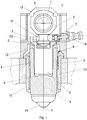
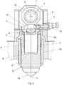
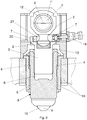
- the figures show a preferred embodiment of part of a radial forging machine with one or more hammers which, according to the invention, can operate as a swaging machine or as a traditional forging press.
- Operating as a swaging machine means an operation of the machine with short hammer working strokes, e.g. in the order of a value either lower than or equal to 80 mm, and high frequencies, e.g. in the order of 2-8 Hz.
- Operating as a traditional forging machine means an operation of the machine with longer working strokes of the hammers, e.g. in the order of a value either lower than or equal to 500 mm, low frequencies, e.g. in the order of a value lower than 3 Hz, and modular forging speed up to a value either lower than or equal to 500 mm/s.
- the machine object of the present invention comprises for each hammer:
- the eccentric shaft 1 is provided with an eccentric portion 1' with respect to first axis X to which the connecting rod 2 is hinged.
- Each hammer adapted to perform an alternating working movement within the respective guiding frame 10 along a second axis Y perpendicular to the first axis X, comprises a hydraulic cylinder 8.
- Such a hydraulic cylinder 8 is provided with a hollow body 5, distal with respect to the connecting rod 2, to which a forging member 15 is externally fixed, and with a piston 3, proximal to the connecting rod 2 and at least partially inserted in the hollow body 5.
- the forging member 15 is preferably always arranged outside the guiding frame 10. However, it cannot be excluded that the forging member 15 is, in a retracted position, at least partially inside the guiding frame 10.
- the piston 3 is coupled in removable manner to the connecting rod 2 ( Fig. 1 and 2 ).
- a low friction member 13 is generally provided, arranged between the piston 3 and the connecting rod 2, integrally fixed to the piston 3 and preferably housed in a cavity of the piston 3 itself.
- the hydraulic cylinder 8 also comprises a hydraulic chamber 6, arranged between piston 3 and hollow body 5, which by introducing a liquid inside, e.g. hydraulic oil, allows to move the hollow body 5, and thus the forging member 15, away from the piston 3. Instead, the hollow body 5 can be moved towards to the piston 3 by letting liquid out from the hydraulic chamber 6.
- a liquid inside e.g. hydraulic oil
- the inlet and outlet channels of the hydraulic oil connected to the hydraulic chamber 6, in common in the hydraulic cylinders, are not shown in the figures.
- uncoupling means are provided for uncoupling the piston 3 from the connecting rod 2.
- such uncoupling means comprise an actuator 18 which actuates a wedge 7, arranged in a cavity 20 of the structure of the machine provided between eccentric shaft 1 and piston 3 and which can move within said cavity, so that when the wedge 7 is in a first operating position, or first end position ( Fig. 2 ), a contact is provided between wedge 7 and piston 3 and a clearance is provided between piston 3 and connecting rod 2, while when the wedge 7 is in a second operating position, or second end position ( Fig. 1 ), a contact is provided between piston 3 and connecting rod 2 and a clearance is provided between wedge 7 and piston 3.
- the actuator 18 can be a hydraulic, pneumatic or mechanical jack, either automatically or manually actuated.
- the actuator 18 is fixed to a frame or main casing of the machine.
- the wedge 7 advantageously has a central hole 21 crossed by the end of the connecting rod 2 proximal to the piston 3.
- the uncoupling means can comprise, for example, a hydraulic slewing ring, electromechanical jacks coaxial with the hammer, disengagement means of the connecting rod with displacement of the connecting rod in rotated position off axis with respect to axis Y, the connecting rod itself but of the variable length type (mechanical or hydraulic).
- the hammer In the first operating position ( Fig. 2 ), i.e. after the uncoupling between piston 3 and connecting rod 2, the hammer can be actuated only hydraulically, in alternating manner, by means of the first hydraulic chamber 6.
- the machine can be made to work with long working strokes, and thus operating in forging press mode by moving the hollow body 5, and thus the forging member 15, alternatively away from or towards the piston 3 as desired, by either filling or emptying the hydraulic chamber 6.
- this operating mode it is further avoided that, during operation, the forging load is discharged onto the connecting rod 2, and thus onto the bearing 12 which is not rotating, because the thrust force on the piston 3 is discharged onto the main frame of the machine by means of the wedge 7 itself.
- the hammer In the second operating position ( Fig. 1 ), i.e. when piston 3 and connecting rod 2 are coupled, the hammer can be actuated mechanically in alternating manner by means of the eccentric shaft 1-connecting rod 2 assembly.
- the machine may work as a swaging machine, with short hammer working strokes and high oscillating frequencies.
- the hydraulic chamber 6 allows only to adjust the average working position of the hammer along the second axis Y by adjusting the amount of liquid therein.
- a maximum pressure valve (not shown), associated to the hydraulic chamber 6, it is possible to prevent discharging the overloads on the connecting rod 2 and, thus, on the bearing 12 also in this operating mode as a swaging machine.
- the liquid can let in and out of the hydraulic chamber 6 by means of a servo valve so as to adjust the average working position of the hammer between one hammering strike and the other rapidly.
- a second hydraulic chamber 4, of annular shape, is further provided between the guiding frame 10 and the hollow body 5 of the cylinder 8.
- This second hydraulic chamber 4 is used to guarantee the constant contact between piston 3 and wedge 7 when the wedge is in said first operating position. In particular, this contact is guaranteed by the hydraulic pressure present in the annular chamber 4, which behaves as a hydraulic compensation spring.
- said first operating condition occurs when the connecting rod 2 and the eccentric portion 1' of the shaft 1 are in high position, with reference to the figures.
- the second hydraulic chamber 4 is used to guarantee the constant contact between piston 3 and connecting rod 2.
- the shortening of the cylinder 8 is guaranteed by the hydraulic pressure in the annular hydraulic chamber 4 which behaves as a hydraulic compensation spring.
- the forging machine of the invention can be of the type with only one hammer or with two or more hammers, e.g. four hammers. In case of multiple hammers, the latter move radially with respect to the longitudinal advancement axis of the product to be processed.
- a kinematic chain connecting the eccentric shafts 1 of the single hammers is provided to synchronize the working strokes of all hammers of the same machine in swaging machine mode.
- the operating method change consists of the following steps:
- step a) the wedge 7 is in said second operating position, with a clearance between wedge 7 and piston 3.
- step b) the wedge 7 is in said first operating position with a contact provided between wedge 7 and piston 3.
Landscapes
- Engineering & Computer Science (AREA)
- Mechanical Engineering (AREA)
- Physics & Mathematics (AREA)
- Fluid Mechanics (AREA)
- Forging (AREA)
- Press Drives And Press Lines (AREA)
Claims (15)
- Machine à forger avec un ou plusieurs marteaux, comprenant pour chaque marteau :- un arbre excentrique (1), adapté pour tourner autour d'un premier axe (X),- une bielle (2), adaptée pour être actionnée par ledit arbre excentrique (1) fonctionnant comme une manivelle,- et un cadre de guidage (10),
dans laquelle le marteau est adapté pour réaliser un mouvement de travail alterné au sein dudit cadre de guidage (10) selon un second axe (Y) perpendiculaire au premier axe (X),
dans laquelle le marteau comprend un vérin hydraulique (8) pourvu d'un corps creux (5), auquel un organe à forger est fixé (15) à l'extérieur, et un piston (3) inséré au moins partiellement au sein dudit corps creux (5) et couplé de façon amovible à la bielle (2),
dans laquelle une première chambre hydraulique (6), agencée entre le piston (3) et le corps creux (5), permet d'éloigner et/ou de rapprocher le corps creux (5) dudit piston (3),
caractérisée en ce que
des moyens de découplage sont prévus pour découpler le piston (3) de la bielle (2), moyennant quoi :- après découplage, le marteau peut être actionné hydrauliquement de manière alternée au moyen de la première chambre hydraulique (6), tandis que- lorsque le piston (3) est couplé à la bielle (2), le marteau peut être actionné mécaniquement de manière alternée au moyen de l'ensemble arbre excentrique (1) - bielle (2), alors que la première chambre hydraulique (6) permet de régler la position de travail moyenne du marteau selon le second axe (Y). - Machine selon la revendication 1, dans laquelle lesdits moyens de découplage comprennent un coin (7) agencé dans une cavité (20) prévue entre l'arbre excentrique (1) et le piston (3), ledit coin (7) étant commandé par un actionneur (18) moyennant quoi, lorsque le coin est dans une première position de fonctionnement, un contact est prévu entre le coin (7) et le piston (3) et un débattement est prévu entre le piston (3) et la bielle (2), tandis que, lorsque le coin est dans une seconde position de fonctionnement, un contact est prévu entre le piston (3) et la bielle (2) et un débattement est prévu entre le coin (7) et le piston (3).
- Machine selon la revendication 1 ou 2, dans laquelle le coin (7) et l'actionneur (18) sont raccordés à un cadre d'une machine.
- Machine selon la revendication 2 ou 3, dans laquelle une seconde chambre hydraulique (4) est prévue, adaptée pour garantir un contact constant entre le piston (3) et le coin (7) lorsque le coin est dans ladite première position de fonctionnement, et adaptée pour garantir un contact constant entre le piston (3) et la bielle (2) lorsque le coin est dans ladite seconde position de fonctionnement.
- Machine selon la revendication 4, dans laquelle ladite seconde chambre hydraulique (4) a une forme annulaire et est prévue entre le cadre de guidage (10) et le corps creux (5).
- Machine selon l'une quelconque des revendications précédentes, dans laquelle la première chambre hydraulique (6) est pourvue d'une soupape de surpression, adaptée pour être actionnée en cas de surcharge lorsque le marteau est actionné mécaniquement.
- Machine selon l'une quelconque des revendications précédentes, dans laquelle la première chambre hydraulique (6) est pourvue d'une servovalve.
- Machine selon l'une quelconque des revendications précédentes, dans laquelle un organe à faible frottement (13) est prévu entre le piston (3) et la bielle (2), de préférence logé dans une cavité du piston (3).
- Machine selon l'une quelconque des revendications précédentes, dans laquelle un palier (12) est prévu entre l'arbre excentrique (1) et la bielle (2).
- Machine selon la revendication 1, dans laquelle lesdits moyens de découplage comprennent une couronne de rotation hydraulique ou des vérins électromécaniques coaxiaux avec le marteau, ou des organes de dégagement de bielle adaptés pour déplacer la bielle vers une position désaxée par rapport au second axe (Y), ou la bielle elle-même, cette dernière étant du type à longueur variable.
- Machine selon l'une quelconque des revendications précédentes, dans laquelle est prévue une pluralité de marteaux mobiles radialement par rapport à l'axe d'avancement longitudinal du produit à usiner, et dans laquelle une chaîne cinématique est prévue, raccordant les arbres excentriques (1) des marteaux seuls, adaptée pour synchroniser les courses de travail des marteaux.
- Procédé de changement pour une machine à forger, selon l'une quelconque des revendications précédentes, d'un fonctionnement en tant que machine à rétreindre à un fonctionnement en tant que presse à forger, le procédé comprenant les étapes suivantes de :a) fourniture du piston (3) et de la bielle (2) en contact réciproque de sorte que le marteau soit actionné mécaniquement de manière alternée au moyen de l'ensemble arbre excentrique (1) - bielle (2), avec la première chambre hydraulique (6) qui permet de régler uniquement la position de travail moyenne du marteau selon le second axe (Y), la machine fonctionnant en tant que machine à rétreindre ;b) découplage du piston (3) de la bielle (2) par l'intermédiaire des moyens de découplage de sorte que le marteau puisse être actionné hydrauliquement de manière alternée, alternant une entrée et une sortie de liquide de la première chambre hydraulique (6), la machine fonctionnant en tant que presse à forger.
- Procédé selon la revendication 12, dans lequel à l'étape a) le coin (7) est dans ladite seconde position de fonctionnement, avec un débattement prédéterminé entre le coin (7) et le piston (3) ; et dans lequel après l'étape b) le coin (7) est dans ladite première position de fonctionnement avec un contact prévu entre le coin (7) et le piston (3).
- Procédé de changement pour une machine à forger selon l'une quelconque des revendications 1 à 10, d'un fonctionnement en tant que presse à forger à un fonctionnement en tant que machine à rétreindre, le procédé comprenant les étapes suivantes de :a) fourniture du piston (3) découplé de la bielle (2) par l'intermédiaire des moyens de découplage de sorte que le marteau puisse être actionné hydrauliquement de manière alternée, alternant une entrée et une sortie de liquide de la première chambre hydraulique (6), la machine fonctionnant en tant que presse à forger ;b) couplage du piston (3) à la bielle (2) de sorte que le marteau soit actionné mécaniquement de manière alternée, au moyen de l'ensemble arbre excentrique (1) - bielle (2), avec la première chambre hydraulique (6) qui permet de régler uniquement la position de travail moyenne du marteau selon le second axe (Y), la machine fonctionnant en tant que machine à rétreindre.
- Procédé selon la revendication 14, dans lequel à l'étape a) le coin (7) est dans ladite première position de fonctionnement, avec un contact entre le coin (7) et le piston (3) ; et dans lequel après l'étape b) le coin (7) est dans ladite seconde position de fonctionnement, avec un débattement entre le coin (7) et le piston (3).
Applications Claiming Priority (2)
| Application Number | Priority Date | Filing Date | Title |
|---|---|---|---|
| ITMI20140185 | 2014-02-10 | ||
| PCT/IB2015/050956 WO2015118502A1 (fr) | 2014-02-10 | 2015-02-09 | Machine de forgeage |
Publications (2)
| Publication Number | Publication Date |
|---|---|
| EP3104992A1 EP3104992A1 (fr) | 2016-12-21 |
| EP3104992B1 true EP3104992B1 (fr) | 2018-04-04 |
Family
ID=50239779
Family Applications (1)
| Application Number | Title | Priority Date | Filing Date |
|---|---|---|---|
| EP15711830.8A Active EP3104992B1 (fr) | 2014-02-10 | 2015-02-09 | Machine et procédé de forgeage |
Country Status (5)
| Country | Link |
|---|---|
| US (1) | US9873146B2 (fr) |
| EP (1) | EP3104992B1 (fr) |
| CN (1) | CN106102955B (fr) |
| RU (1) | RU2650369C2 (fr) |
| WO (1) | WO2015118502A1 (fr) |
Families Citing this family (11)
| Publication number | Priority date | Publication date | Assignee | Title |
|---|---|---|---|---|
| CN106623719B (zh) * | 2017-02-24 | 2019-04-26 | 王安基 | 锻造机构及锻机 |
| CN109751289B (zh) * | 2019-01-21 | 2020-07-03 | 太原理工大学 | 一种液力混合式径向锻造机液压系统 |
| CN111421870B (zh) * | 2020-04-01 | 2021-07-16 | 浙江广厦建设职业技术学院 | 一种室内异形棚顶智能加工装置 |
| CN111790869B (zh) * | 2020-06-08 | 2022-03-29 | 天长市振业建设工程有限公司 | 一种建筑工地撬棍制作用敲击装置 |
| CN112916782B (zh) * | 2021-02-07 | 2023-06-20 | 哈尔滨工业大学 | 一种带有局部突变特征的超长薄腹板高筋复杂构件的局部渐进加载精密成形模具及方法 |
| CN113617996B (zh) * | 2021-03-02 | 2023-06-20 | 天津重型装备工程研究有限公司 | 一种圈类锻件的体外锻造方法 |
| AT525034B1 (de) | 2021-05-12 | 2024-09-15 | Gfm Gmbh | Verfahren zum Warmumformen eines gegossenen Schmiedeblocks mithilfe einer Schmiedevorrichtung |
| CN113290190B (zh) * | 2021-05-20 | 2022-08-05 | 唐山盛通锻造有限公司 | 一种锻造模具 |
| CN115090813A (zh) * | 2022-05-18 | 2022-09-23 | 安徽钜将家具制造有限公司 | 一种五金零件智能锻造设备及零件锻造工艺 |
| CN115971389B (zh) * | 2022-11-11 | 2023-07-28 | 中机锻压江苏股份有限公司 | 一种全液压随动锤 |
| CN116511393B (zh) * | 2023-05-22 | 2023-12-29 | 浙江利源重工科技有限公司 | 一种连续锤击的电液锤 |
Citations (7)
| Publication number | Priority date | Publication date | Assignee | Title |
|---|---|---|---|---|
| JPS58215235A (ja) | 1982-06-10 | 1983-12-14 | Sumitomo Heavy Ind Ltd | 鍛造プレス |
| GB2157602A (en) | 1984-04-21 | 1985-10-30 | Eumuco Ag Fuer Maschinenbau | Drop forging work pieces |
| DE3507327A1 (de) | 1985-03-01 | 1986-09-04 | Jörg 8607 Hollfeld Lange | Exzenter-hydraulikpresse |
| EP0667197B1 (fr) | 1994-01-18 | 1997-10-08 | GFM Gesellschaft für Fertigungstechnik und Maschinenbau Aktiengesellschaft | Machine à forger |
| EP0829319A2 (fr) | 1996-09-17 | 1998-03-18 | Gfm Holding Ag | Machine à forger |
| EP0993888A2 (fr) | 1998-10-13 | 2000-04-19 | GFM Beteiligungs- und Management GmbH & Co KG | Machine à forger |
| EP1093871A2 (fr) | 1999-10-07 | 2001-04-25 | GFM Beteiligungs- und Management GmbH & Co KG | Machine à forger |
Family Cites Families (6)
| Publication number | Priority date | Publication date | Assignee | Title |
|---|---|---|---|---|
| SU565445A1 (ru) * | 1974-01-03 | 1979-05-30 | Экспериментальный научно-исследовательский институт кузнечно-прессового машиностроения | Радиально-ковочна машина |
| CN2048793U (zh) * | 1989-01-03 | 1989-12-06 | 济南铸造锻压机械研究所 | 二锤头径向锻造机 |
| SU1819181A3 (ru) * | 1991-12-10 | 1993-05-30 | Leonid G Konev | Радиально-ковочная машина |
| US5353011A (en) | 1993-01-04 | 1994-10-04 | Checkpoint Systems, Inc. | Electronic article security system with digital signal processing and increased detection range |
| CN101412068A (zh) * | 2007-10-19 | 2009-04-22 | 运通工业股份有限公司 | 立式锻造机 |
| CN202270900U (zh) * | 2011-08-01 | 2012-06-13 | 江阴南工锻造有限公司 | 一种双向同步锻压机构 |
-
2015
- 2015-02-09 RU RU2016135951A patent/RU2650369C2/ru active
- 2015-02-09 WO PCT/IB2015/050956 patent/WO2015118502A1/fr not_active Ceased
- 2015-02-09 CN CN201580006991.7A patent/CN106102955B/zh active Active
- 2015-02-09 US US15/115,873 patent/US9873146B2/en not_active Expired - Fee Related
- 2015-02-09 EP EP15711830.8A patent/EP3104992B1/fr active Active
Patent Citations (7)
| Publication number | Priority date | Publication date | Assignee | Title |
|---|---|---|---|---|
| JPS58215235A (ja) | 1982-06-10 | 1983-12-14 | Sumitomo Heavy Ind Ltd | 鍛造プレス |
| GB2157602A (en) | 1984-04-21 | 1985-10-30 | Eumuco Ag Fuer Maschinenbau | Drop forging work pieces |
| DE3507327A1 (de) | 1985-03-01 | 1986-09-04 | Jörg 8607 Hollfeld Lange | Exzenter-hydraulikpresse |
| EP0667197B1 (fr) | 1994-01-18 | 1997-10-08 | GFM Gesellschaft für Fertigungstechnik und Maschinenbau Aktiengesellschaft | Machine à forger |
| EP0829319A2 (fr) | 1996-09-17 | 1998-03-18 | Gfm Holding Ag | Machine à forger |
| EP0993888A2 (fr) | 1998-10-13 | 2000-04-19 | GFM Beteiligungs- und Management GmbH & Co KG | Machine à forger |
| EP1093871A2 (fr) | 1999-10-07 | 2001-04-25 | GFM Beteiligungs- und Management GmbH & Co KG | Machine à forger |
Also Published As
| Publication number | Publication date |
|---|---|
| EP3104992A1 (fr) | 2016-12-21 |
| RU2016135951A3 (fr) | 2018-03-15 |
| WO2015118502A1 (fr) | 2015-08-13 |
| RU2650369C2 (ru) | 2018-04-11 |
| RU2016135951A (ru) | 2018-03-15 |
| US9873146B2 (en) | 2018-01-23 |
| CN106102955B (zh) | 2018-04-03 |
| US20170008067A1 (en) | 2017-01-12 |
| CN106102955A (zh) | 2016-11-09 |
Similar Documents
| Publication | Publication Date | Title |
|---|---|---|
| EP3104992B1 (fr) | Machine et procédé de forgeage | |
| EP0050466A1 (fr) | Dispositif rotatif pour manoeuvrer une soupape | |
| CN104285065B (zh) | 用于压力传送的液压气动装置和铆接装置 | |
| US5868555A (en) | Hydraulic drive unit of a press machine and a swash plate type variable capacity axial piston pump to use for said device | |
| EP2539592B1 (fr) | Intensificateur d'énergie hydraulique s'appuyant sur le maintien de la position atteinte et de la force | |
| JP2020536748A (ja) | 円形ブランクをスタンピングするためのスタンピングプレス及び方法 | |
| CA1186942A (fr) | Presse de forge sur socle, avec piston fixe enferme dans un cylindre alternatif et commande par fluide sous pression admis par un alesage dans le piston | |
| NO342498B1 (no) | Helisk kileaktuator | |
| US6510786B1 (en) | Hydromechanical press drive | |
| US3416352A (en) | Press for deforming plastic stock | |
| GB2151540A (en) | Screw press | |
| US4272980A (en) | Load equalizer for press tooling | |
| US8984922B2 (en) | Method of and apparatus for positioning a tool | |
| CN110280615B (zh) | 一种挤压轴快速更换与锁紧装置及方法 | |
| EP0933553A2 (fr) | Ressort à gaz de type manchon | |
| DE102005047600A1 (de) | Handwerkzeugmaschine mit einer Welle und mit einem auf der Welle gelagerten Hubantriebslager | |
| US3402592A (en) | Manipulators | |
| US1239862A (en) | Riveting-machine. | |
| JP6781609B2 (ja) | 流体圧シリンダ | |
| ITMI960695A1 (it) | Dispositivo di azionamento per una ripresa | |
| US2656744A (en) | Die adjusting mechanism | |
| EP3972843B1 (fr) | Arbre de serrage, unité de cylindre d'impression et procédé de fonctionnement d'un arbre de serrage | |
| EP3677797B1 (fr) | Actionneur comportant un élément de couple central | |
| EP1614527A8 (fr) | Presse mecanique | |
| CN120868094A (zh) | 一种大型环锻压机用油缸、锻压系统及锻压方法 |
Legal Events
| Date | Code | Title | Description |
|---|---|---|---|
| PUAI | Public reference made under article 153(3) epc to a published international application that has entered the european phase |
Free format text: ORIGINAL CODE: 0009012 |
|
| STAA | Information on the status of an ep patent application or granted ep patent |
Free format text: STATUS: REQUEST FOR EXAMINATION WAS MADE |
|
| 17P | Request for examination filed |
Effective date: 20160908 |
|
| AK | Designated contracting states |
Kind code of ref document: A1 Designated state(s): AL AT BE BG CH CY CZ DE DK EE ES FI FR GB GR HR HU IE IS IT LI LT LU LV MC MK MT NL NO PL PT RO RS SE SI SK SM TR |
|
| AX | Request for extension of the european patent |
Extension state: BA ME |
|
| DAX | Request for extension of the european patent (deleted) | ||
| GRAP | Despatch of communication of intention to grant a patent |
Free format text: ORIGINAL CODE: EPIDOSNIGR1 |
|
| STAA | Information on the status of an ep patent application or granted ep patent |
Free format text: STATUS: GRANT OF PATENT IS INTENDED |
|
| INTG | Intention to grant announced |
Effective date: 20170620 |
|
| GRAS | Grant fee paid |
Free format text: ORIGINAL CODE: EPIDOSNIGR3 |
|
| GRAJ | Information related to disapproval of communication of intention to grant by the applicant or resumption of examination proceedings by the epo deleted |
Free format text: ORIGINAL CODE: EPIDOSDIGR1 |
|
| GRAL | Information related to payment of fee for publishing/printing deleted |
Free format text: ORIGINAL CODE: EPIDOSDIGR3 |
|
| STAA | Information on the status of an ep patent application or granted ep patent |
Free format text: STATUS: REQUEST FOR EXAMINATION WAS MADE |
|
| GRAP | Despatch of communication of intention to grant a patent |
Free format text: ORIGINAL CODE: EPIDOSNIGR1 |
|
| STAA | Information on the status of an ep patent application or granted ep patent |
Free format text: STATUS: GRANT OF PATENT IS INTENDED |
|
| INTC | Intention to grant announced (deleted) | ||
| RAP1 | Party data changed (applicant data changed or rights of an application transferred) |
Owner name: DANIELI & C. OFFICINE MECCANICHE S.P.A. |
|
| INTG | Intention to grant announced |
Effective date: 20171206 |
|
| GRAA | (expected) grant |
Free format text: ORIGINAL CODE: 0009210 |
|
| STAA | Information on the status of an ep patent application or granted ep patent |
Free format text: STATUS: THE PATENT HAS BEEN GRANTED |
|
| AK | Designated contracting states |
Kind code of ref document: B1 Designated state(s): AL AT BE BG CH CY CZ DE DK EE ES FI FR GB GR HR HU IE IS IT LI LT LU LV MC MK MT NL NO PL PT RO RS SE SI SK SM TR |
|
| REG | Reference to a national code |
Ref country code: GB Ref legal event code: FG4D |
|
| REG | Reference to a national code |
Ref country code: CH Ref legal event code: EP |
|
| REG | Reference to a national code |
Ref country code: AT Ref legal event code: REF Ref document number: 985048 Country of ref document: AT Kind code of ref document: T Effective date: 20180415 |
|
| REG | Reference to a national code |
Ref country code: IE Ref legal event code: FG4D |
|
| REG | Reference to a national code |
Ref country code: DE Ref legal event code: R096 Ref document number: 602015009576 Country of ref document: DE |
|
| REG | Reference to a national code |
Ref country code: NL Ref legal event code: MP Effective date: 20180404 |
|
| REG | Reference to a national code |
Ref country code: LT Ref legal event code: MG4D |
|
| PG25 | Lapsed in a contracting state [announced via postgrant information from national office to epo] |
Ref country code: NL Free format text: LAPSE BECAUSE OF FAILURE TO SUBMIT A TRANSLATION OF THE DESCRIPTION OR TO PAY THE FEE WITHIN THE PRESCRIBED TIME-LIMIT Effective date: 20180404 |
|
| PG25 | Lapsed in a contracting state [announced via postgrant information from national office to epo] |
Ref country code: NO Free format text: LAPSE BECAUSE OF FAILURE TO SUBMIT A TRANSLATION OF THE DESCRIPTION OR TO PAY THE FEE WITHIN THE PRESCRIBED TIME-LIMIT Effective date: 20180704 Ref country code: PL Free format text: LAPSE BECAUSE OF FAILURE TO SUBMIT A TRANSLATION OF THE DESCRIPTION OR TO PAY THE FEE WITHIN THE PRESCRIBED TIME-LIMIT Effective date: 20180404 Ref country code: LT Free format text: LAPSE BECAUSE OF FAILURE TO SUBMIT A TRANSLATION OF THE DESCRIPTION OR TO PAY THE FEE WITHIN THE PRESCRIBED TIME-LIMIT Effective date: 20180404 Ref country code: ES Free format text: LAPSE BECAUSE OF FAILURE TO SUBMIT A TRANSLATION OF THE DESCRIPTION OR TO PAY THE FEE WITHIN THE PRESCRIBED TIME-LIMIT Effective date: 20180404 Ref country code: SE Free format text: LAPSE BECAUSE OF FAILURE TO SUBMIT A TRANSLATION OF THE DESCRIPTION OR TO PAY THE FEE WITHIN THE PRESCRIBED TIME-LIMIT Effective date: 20180404 Ref country code: AL Free format text: LAPSE BECAUSE OF FAILURE TO SUBMIT A TRANSLATION OF THE DESCRIPTION OR TO PAY THE FEE WITHIN THE PRESCRIBED TIME-LIMIT Effective date: 20180404 Ref country code: FI Free format text: LAPSE BECAUSE OF FAILURE TO SUBMIT A TRANSLATION OF THE DESCRIPTION OR TO PAY THE FEE WITHIN THE PRESCRIBED TIME-LIMIT Effective date: 20180404 Ref country code: BG Free format text: LAPSE BECAUSE OF FAILURE TO SUBMIT A TRANSLATION OF THE DESCRIPTION OR TO PAY THE FEE WITHIN THE PRESCRIBED TIME-LIMIT Effective date: 20180704 |
|
| PG25 | Lapsed in a contracting state [announced via postgrant information from national office to epo] |
Ref country code: HR Free format text: LAPSE BECAUSE OF FAILURE TO SUBMIT A TRANSLATION OF THE DESCRIPTION OR TO PAY THE FEE WITHIN THE PRESCRIBED TIME-LIMIT Effective date: 20180404 Ref country code: RS Free format text: LAPSE BECAUSE OF FAILURE TO SUBMIT A TRANSLATION OF THE DESCRIPTION OR TO PAY THE FEE WITHIN THE PRESCRIBED TIME-LIMIT Effective date: 20180404 Ref country code: LV Free format text: LAPSE BECAUSE OF FAILURE TO SUBMIT A TRANSLATION OF THE DESCRIPTION OR TO PAY THE FEE WITHIN THE PRESCRIBED TIME-LIMIT Effective date: 20180404 Ref country code: GR Free format text: LAPSE BECAUSE OF FAILURE TO SUBMIT A TRANSLATION OF THE DESCRIPTION OR TO PAY THE FEE WITHIN THE PRESCRIBED TIME-LIMIT Effective date: 20180705 |
|
| REG | Reference to a national code |
Ref country code: AT Ref legal event code: MK05 Ref document number: 985048 Country of ref document: AT Kind code of ref document: T Effective date: 20180404 |
|
| PG25 | Lapsed in a contracting state [announced via postgrant information from national office to epo] |
Ref country code: PT Free format text: LAPSE BECAUSE OF FAILURE TO SUBMIT A TRANSLATION OF THE DESCRIPTION OR TO PAY THE FEE WITHIN THE PRESCRIBED TIME-LIMIT Effective date: 20180806 |
|
| REG | Reference to a national code |
Ref country code: DE Ref legal event code: R026 Ref document number: 602015009576 Country of ref document: DE |
|
| PLBI | Opposition filed |
Free format text: ORIGINAL CODE: 0009260 |
|
| PLAX | Notice of opposition and request to file observation + time limit sent |
Free format text: ORIGINAL CODE: EPIDOSNOBS2 |
|
| PG25 | Lapsed in a contracting state [announced via postgrant information from national office to epo] |
Ref country code: EE Free format text: LAPSE BECAUSE OF FAILURE TO SUBMIT A TRANSLATION OF THE DESCRIPTION OR TO PAY THE FEE WITHIN THE PRESCRIBED TIME-LIMIT Effective date: 20180404 Ref country code: DK Free format text: LAPSE BECAUSE OF FAILURE TO SUBMIT A TRANSLATION OF THE DESCRIPTION OR TO PAY THE FEE WITHIN THE PRESCRIBED TIME-LIMIT Effective date: 20180404 Ref country code: SK Free format text: LAPSE BECAUSE OF FAILURE TO SUBMIT A TRANSLATION OF THE DESCRIPTION OR TO PAY THE FEE WITHIN THE PRESCRIBED TIME-LIMIT Effective date: 20180404 Ref country code: CZ Free format text: LAPSE BECAUSE OF FAILURE TO SUBMIT A TRANSLATION OF THE DESCRIPTION OR TO PAY THE FEE WITHIN THE PRESCRIBED TIME-LIMIT Effective date: 20180404 Ref country code: AT Free format text: LAPSE BECAUSE OF FAILURE TO SUBMIT A TRANSLATION OF THE DESCRIPTION OR TO PAY THE FEE WITHIN THE PRESCRIBED TIME-LIMIT Effective date: 20180404 Ref country code: RO Free format text: LAPSE BECAUSE OF FAILURE TO SUBMIT A TRANSLATION OF THE DESCRIPTION OR TO PAY THE FEE WITHIN THE PRESCRIBED TIME-LIMIT Effective date: 20180404 |
|
| 26 | Opposition filed |
Opponent name: SMS GROUP GMBH Effective date: 20190104 |
|
| PG25 | Lapsed in a contracting state [announced via postgrant information from national office to epo] |
Ref country code: SM Free format text: LAPSE BECAUSE OF FAILURE TO SUBMIT A TRANSLATION OF THE DESCRIPTION OR TO PAY THE FEE WITHIN THE PRESCRIBED TIME-LIMIT Effective date: 20180404 |
|
| PG25 | Lapsed in a contracting state [announced via postgrant information from national office to epo] |
Ref country code: SI Free format text: LAPSE BECAUSE OF FAILURE TO SUBMIT A TRANSLATION OF THE DESCRIPTION OR TO PAY THE FEE WITHIN THE PRESCRIBED TIME-LIMIT Effective date: 20180404 |
|
| REG | Reference to a national code |
Ref country code: CH Ref legal event code: PL |
|
| GBPC | Gb: european patent ceased through non-payment of renewal fee |
Effective date: 20190209 |
|
| PG25 | Lapsed in a contracting state [announced via postgrant information from national office to epo] |
Ref country code: LU Free format text: LAPSE BECAUSE OF NON-PAYMENT OF DUE FEES Effective date: 20190209 Ref country code: MC Free format text: LAPSE BECAUSE OF FAILURE TO SUBMIT A TRANSLATION OF THE DESCRIPTION OR TO PAY THE FEE WITHIN THE PRESCRIBED TIME-LIMIT Effective date: 20180404 |
|
| REG | Reference to a national code |
Ref country code: BE Ref legal event code: MM Effective date: 20190228 |
|
| REG | Reference to a national code |
Ref country code: IE Ref legal event code: MM4A |
|
| PG25 | Lapsed in a contracting state [announced via postgrant information from national office to epo] |
Ref country code: CH Free format text: LAPSE BECAUSE OF NON-PAYMENT OF DUE FEES Effective date: 20190228 Ref country code: LI Free format text: LAPSE BECAUSE OF NON-PAYMENT OF DUE FEES Effective date: 20190228 |
|
| PG25 | Lapsed in a contracting state [announced via postgrant information from national office to epo] |
Ref country code: IE Free format text: LAPSE BECAUSE OF NON-PAYMENT OF DUE FEES Effective date: 20190209 Ref country code: GB Free format text: LAPSE BECAUSE OF NON-PAYMENT OF DUE FEES Effective date: 20190209 |
|
| PG25 | Lapsed in a contracting state [announced via postgrant information from national office to epo] |
Ref country code: FR Free format text: LAPSE BECAUSE OF NON-PAYMENT OF DUE FEES Effective date: 20190228 Ref country code: BE Free format text: LAPSE BECAUSE OF NON-PAYMENT OF DUE FEES Effective date: 20190228 |
|
| PG25 | Lapsed in a contracting state [announced via postgrant information from national office to epo] |
Ref country code: TR Free format text: LAPSE BECAUSE OF FAILURE TO SUBMIT A TRANSLATION OF THE DESCRIPTION OR TO PAY THE FEE WITHIN THE PRESCRIBED TIME-LIMIT Effective date: 20180404 |
|
| REG | Reference to a national code |
Ref country code: DE Ref legal event code: R100 Ref document number: 602015009576 Country of ref document: DE |
|
| PG25 | Lapsed in a contracting state [announced via postgrant information from national office to epo] |
Ref country code: MT Free format text: LAPSE BECAUSE OF NON-PAYMENT OF DUE FEES Effective date: 20190209 |
|
| PLCK | Communication despatched that opposition was rejected |
Free format text: ORIGINAL CODE: EPIDOSNREJ1 |
|
| PLBN | Opposition rejected |
Free format text: ORIGINAL CODE: 0009273 |
|
| STAA | Information on the status of an ep patent application or granted ep patent |
Free format text: STATUS: OPPOSITION REJECTED |
|
| 27O | Opposition rejected |
Effective date: 20200527 |
|
| PG25 | Lapsed in a contracting state [announced via postgrant information from national office to epo] |
Ref country code: CY Free format text: LAPSE BECAUSE OF FAILURE TO SUBMIT A TRANSLATION OF THE DESCRIPTION OR TO PAY THE FEE WITHIN THE PRESCRIBED TIME-LIMIT Effective date: 20180404 |
|
| PG25 | Lapsed in a contracting state [announced via postgrant information from national office to epo] |
Ref country code: IS Free format text: LAPSE BECAUSE OF FAILURE TO SUBMIT A TRANSLATION OF THE DESCRIPTION OR TO PAY THE FEE WITHIN THE PRESCRIBED TIME-LIMIT Effective date: 20180804 |
|
| PG25 | Lapsed in a contracting state [announced via postgrant information from national office to epo] |
Ref country code: HU Free format text: LAPSE BECAUSE OF FAILURE TO SUBMIT A TRANSLATION OF THE DESCRIPTION OR TO PAY THE FEE WITHIN THE PRESCRIBED TIME-LIMIT; INVALID AB INITIO Effective date: 20150209 |
|
| PG25 | Lapsed in a contracting state [announced via postgrant information from national office to epo] |
Ref country code: MK Free format text: LAPSE BECAUSE OF FAILURE TO SUBMIT A TRANSLATION OF THE DESCRIPTION OR TO PAY THE FEE WITHIN THE PRESCRIBED TIME-LIMIT Effective date: 20180404 |
|
| P01 | Opt-out of the competence of the unified patent court (upc) registered |
Effective date: 20230511 |
|
| PGFP | Annual fee paid to national office [announced via postgrant information from national office to epo] |
Ref country code: DE Payment date: 20260227 Year of fee payment: 12 |
|
| PGFP | Annual fee paid to national office [announced via postgrant information from national office to epo] |
Ref country code: IT Payment date: 20260219 Year of fee payment: 12 |