EP3105109B1 - Poids lourd modulaire ajustable en largeur et module de châssis transversal pour un poids lourd de ce type - Google Patents
Poids lourd modulaire ajustable en largeur et module de châssis transversal pour un poids lourd de ce type Download PDFInfo
- Publication number
- EP3105109B1 EP3105109B1 EP15705948.6A EP15705948A EP3105109B1 EP 3105109 B1 EP3105109 B1 EP 3105109B1 EP 15705948 A EP15705948 A EP 15705948A EP 3105109 B1 EP3105109 B1 EP 3105109B1
- Authority
- EP
- European Patent Office
- Prior art keywords
- vehicle
- cross
- heavy goods
- hand
- transverse frame
- Prior art date
- Legal status (The legal status is an assumption and is not a legal conclusion. Google has not performed a legal analysis and makes no representation as to the accuracy of the status listed.)
- Active
Links
Images


Classifications
-
- B—PERFORMING OPERATIONS; TRANSPORTING
- B62—LAND VEHICLES FOR TRAVELLING OTHERWISE THAN ON RAILS
- B62D—MOTOR VEHICLES; TRAILERS
- B62D63/00—Motor vehicles or trailers not otherwise provided for
- B62D63/06—Trailers
- B62D63/061—Foldable, extensible or yielding trailers
-
- B—PERFORMING OPERATIONS; TRANSPORTING
- B60—VEHICLES IN GENERAL
- B60D—VEHICLE CONNECTIONS
- B60D1/00—Traction couplings; Hitches; Draw-gear; Towing devices
- B60D1/48—Traction couplings; Hitches; Draw-gear; Towing devices characterised by the mounting
- B60D1/481—Traction couplings; Hitches; Draw-gear; Towing devices characterised by the mounting adapted for being mounted to the front and back of trailers, carts, trolleys or the like to form a train
-
- B—PERFORMING OPERATIONS; TRANSPORTING
- B62—LAND VEHICLES FOR TRAVELLING OTHERWISE THAN ON RAILS
- B62D—MOTOR VEHICLES; TRAILERS
- B62D13/00—Steering specially adapted for trailers
- B62D13/02—Steering specially adapted for trailers for centrally-pivoted axles
- B62D13/025—Steering specially adapted for trailers for centrally-pivoted axles the pivoted movement being initiated by the coupling means between tractor and trailer
-
- B—PERFORMING OPERATIONS; TRANSPORTING
- B62—LAND VEHICLES FOR TRAVELLING OTHERWISE THAN ON RAILS
- B62D—MOTOR VEHICLES; TRAILERS
- B62D21/00—Understructures, i.e. chassis frame on which a vehicle body may be mounted
- B62D21/14—Understructures, i.e. chassis frame on which a vehicle body may be mounted of adjustable length or width
-
- B—PERFORMING OPERATIONS; TRANSPORTING
- B62—LAND VEHICLES FOR TRAVELLING OTHERWISE THAN ON RAILS
- B62D—MOTOR VEHICLES; TRAILERS
- B62D63/00—Motor vehicles or trailers not otherwise provided for
- B62D63/02—Motor vehicles
- B62D63/025—Modular vehicles
-
- B—PERFORMING OPERATIONS; TRANSPORTING
- B62—LAND VEHICLES FOR TRAVELLING OTHERWISE THAN ON RAILS
- B62D—MOTOR VEHICLES; TRAILERS
- B62D63/00—Motor vehicles or trailers not otherwise provided for
- B62D63/06—Trailers
- B62D63/068—Trailers with more than two axles or more than four wheels
-
- B—PERFORMING OPERATIONS; TRANSPORTING
- B60—VEHICLES IN GENERAL
- B60P—VEHICLES ADAPTED FOR LOAD TRANSPORTATION OR TO TRANSPORT, TO CARRY, OR TO COMPRISE SPECIAL LOADS OR OBJECTS
- B60P1/00—Vehicles predominantly for transporting loads and modified to facilitate loading, consolidating the load, or unloading
- B60P1/02—Vehicles predominantly for transporting loads and modified to facilitate loading, consolidating the load, or unloading with parallel up-and-down movement of load supporting or containing element
- B60P1/027—Vehicles predominantly for transporting loads and modified to facilitate loading, consolidating the load, or unloading with parallel up-and-down movement of load supporting or containing element with relative displacement of the wheel axles
Definitions
- the invention relates to a modular heavy-duty vehicle according to the preamble of claim 1.
- directional information for example, “left”, “right”, “front”, “rear” and the like, refer to a ready for driving state of the modular heavy-duty vehicle on the one hand and on the other Understand viewing direction coinciding with the forward direction of travel of the modular heavy-duty vehicle.
- This roadworthy condition and this direction of view are also the basis of the description of the individual modules that make up the modular heavy-duty vehicle.
- Modular heavy duty vehicles or modules for such modular heavy duty vehicles have been successfully distributed by the Applicant for many years.
- the basic principle of the modular design is that the transport companies are provided with a modular system of modules that can be combined, from which a vehicle suitable for transporting the respective load can be assembled for each transport order.
- the Applicant has also developed the generic modular heavy-duty vehicles which have a vehicle frame divided in the vehicle longitudinal center plane so that the desired vehicle length is achieved not only by arranging a plurality of vehicle modules in a row can be obtained, but by the arrangement of extending in the vehicle width direction connecting units between the left and right vehicle modules and the desired vehicle width. In this way, for example, vehicle widths of up to 6100 mm (20 feet) can be achieved.
- a heavy duty vehicle which comprises two longitudinal frame parts, which are attached to transverse frame modules, wherein the transverse frame modules are variable in length. Furthermore, be on the DE 20 2012 011898 U1 pointed.
- variable-length transverse frame modules according to the invention form further "building blocks" of the modular system which can be made available to the transport company.
- transverse frame module is used in the context of the present invention in the sense that in each transverse frame module all functional elements are included, which are required for the provision of the length variability, so that the left and right vehicle modules with their extending in the vehicle longitudinal direction left and right longitudinal frame parts are formed free of required for the provision of the length variability functional elements.
- the transverse frame modules can be combined with any trained, in particular already owned by transport companies, left and right vehicle modules, as long as they can be connected to these only operationally strong, to ultimately obtain a width-adjustable modular heavy-duty vehicle.
- the subject matter of the present invention also includes modular heavy duty vehicles in which, in addition to the left and right vehicle modules with their extending in the vehicle longitudinal direction left and right longitudinal frame parts and the two variable-length transverse frame modules more modules are available.
- the vehicle longitudinal direction further left and right vehicle modules connect, which in turn are completed with another variable-length cross-frame module.
- a length-adjustable transverse frame module should be provided approximately every 10 m.
- At least one transverse frame module preferably all length-adjustable transverse frame modules, telescopically interlocking, comprising a cavity enclosing transverse frame parts, wherein in the cavity at least one of the change in length of the transverse frame module effecting force device is arranged.
- the power device can be, for example, a hydraulically and / or pneumatically actuated force device.
- the at least one transverse frame module may comprise a central transverse frame part with two side sections and two lateral transverse frame parts which engage around the side sections of the central transverse frame part and are displaceable relative thereto.
- a central portion may be provided, which is preferably formed integrally with the two side portions. While the two lateral frame parts may be used for attaching functional elements which are also adjusted in the width direction of the vehicle when the width of the vehicle is changed, the middle section may serve for the attachment of functional elements which are not adjusted in the width direction of the vehicle when the vehicle width is changed should.
- the functional elements which are also adjusted in a change in the vehicle width in the width direction of the vehicle, for example, be coupling elements for coupling the transverse frame module to the left and right vehicle modules and / or coupling elements for coupling the cross-frame module as an intermediary between a plurality of successively arranged vehicle modules in the assembly of a modular heavy-duty vehicle having in the vehicle longitudinal direction over a plurality of successively arranged left and right vehicle modules, and / or hinged ramps, for example for a vehicle to be transported on the modular heavy-duty vehicle.
- the functional elements which are not to be adjusted in the width direction of the vehicle in a change in the vehicle width for example, coupling elements for coupling the transverse frame module to a width-non-adjustable vehicle module and / or coupling elements for attaching a drawbar assembly.
- At least one of the transverse frame modules is releasably securable to the end face of the respective associated longitudinal end of the two longitudinal frame parts.
- the existing at the left and right vehicle modules for connection to other left and right vehicle modules anyway coupling elements can also be used to connect the transverse frame modules with the left and right vehicle modules.
- a first embodiment variant of a transverse frame module according to the invention may, for example, have on its front side coupling elements for attaching a drawbar assembly and on its rear side coupling elements for coupling the transverse frame module to the left and right vehicle modules.
- Such a transverse frame module may be provided, for example, at the front end of the modular heavy-duty vehicle for attachment of the drawbar.
- such a transverse frame module can also be provided at the rear end of the modular heavy-duty vehicle.
- a second embodiment variant of a transverse frame module according to the invention can, for example, on its front side coupling elements for coupling the transverse frame module to the left and right vehicle modules and on its rear side hinged ramps, for example for a vehicle to be transported on the modular heavy-duty vehicle have.
- Such a transverse frame module will preferably be arranged at the rear end of the modular heavy-duty vehicle.
- a third embodiment variant of a transverse frame module according to the invention can, for example, have coupling elements for coupling the transverse frame module to left and right vehicle modules both on its front side and on its rear side.
- This type of cross-frame module is preferably used for assembling longer width-adjustable heavy duty vehicles from a variety of right and left vehicle modules. To ensure the stability of the heavy-duty vehicle, it is advantageous, as already mentioned above, if such a transverse frame module is provided approximately every 10 m.
- a fourth embodiment variant of a transverse frame module according to the invention for example, on the front side coupling elements for coupling the transverse frame module to the left and right vehicle modules and on the rear side coupling elements for coupling the transverse frame module to a vehicle module not adjustable in width.
- each of the lateral transverse frame parts may be associated with a separate force device, one end of which acts on the central transverse frame part and the other end on the respective lateral transverse frame part.
- This has the advantage that each of the force devices can be made weaker and thus smaller and less expensive than if the force required for width adjustment would have to be generated by a single force device.
- this embodiment makes it possible in the transverse frame module, for example in the middle section of the central transverse frame part, through openings for the passage of Functional elements, in particular for the passage of handlebars to provide.
- the at least one transverse frame module may have a rectangular or square profile in a section substantially orthogonal to the vehicle width direction, wherein two of the side surfaces of the rectangular or square profile preferably extend substantially orthogonal to the vehicle longitudinal direction.
- the telescopically interlocking frame elements for example, each of the lateral transverse frame parts and the respectively associated side portion of the central transverse frame part, in a detachable manner operatively connected to each other.
- the lateral transverse frame members may have a through-hole for passing an engaging bolt and the associated side portions of the central transverse frame member having a plurality of engaging recesses or engaging recesses into which the engaging bolt is insertable.
- the engagement bolt may, for example, be a smooth-surfaced pin which engages smooth-walled engagement recesses or engagement recesses and is biased, for example spring biased, into this engaged position.
- the engagement bolt may be an externally threaded bolt and the engagement recesses or engagement recesses may be formed with a corresponding mating thread.
- a display which indicates the relative position of the lateral transverse frame part and the associated side section of the central transverse frame part.
- This display may comprise, for example, a window in the lateral transverse frame part, in FIG in each case one of a plurality of markings can be seen, which are associated with the engagement recesses or engagement recesses.
- both lateral transverse frame parts occupy the same relative position relative to the respectively associated side section of the central transverse frame part.
- a steering angle forwarding element connected to an input steering rod of the drawbar-controlled steering is provided, which can be pivoted relative to the drawbar and detachably connected to the drawbar in at least one relative pivoting position is.
- the axis about which the steering angle-passing element is pivotable relative to the drawbar is identical to the axis about which the drawbar is pivotable relative to the modular heavy-duty vehicle.
- the changes in the steering angle ratio in relative pivoting of drawbar and Lenkwinkelweiter effetselement can be controlled in a simple manner.
- the drawbar or an element connected to it via a through hole for passing an engaging bolt and the steering angle relay element over a plurality of engagement recesses or engagement recesses have, in which the engagement bolt is inserted and each of which corresponds to a predetermined vehicle width.
- the plurality of engagement recesses or engagement recesses may be provided with markings, preferably with markers corresponding to those on the transverse frame modules, to facilitate an operator's perceptual adjustment of the transverse frame modules and the drawbar steering to each other. It is therefore advantageous if between the engagement recesses or engagement recesses of the steering angle relay element and those of the transverse frame module is a fixed assignment.
- a modular heavy duty vehicle according to the invention is generally designated 10.
- the heavy vehicle 10 comprises a left vehicle module 12 and a right vehicle module 14, a front cross frame module 16 and a rear cross frame module 18, which are identical in the illustrated embodiment.
- the left-hand vehicle module 12 comprises a left-hand longitudinal frame part 20, on which a plurality of left-hand wheel assemblies 22 arranged one behind the other in the longitudinal direction L of the heavy-duty vehicle 10 are arranged.
- the right-hand vehicle module 14 comprises a right-hand longitudinal frame part 24 on which a plurality of left-hand wheel assemblies 26 arranged one behind the other in the longitudinal direction L (see FIG FIGS. 3 and 4 ) is arranged.
- the two transverse frame modules 16, 18 are arranged at the two longitudinal ends of the longitudinal frame members 20 and 24 and operatively connected thereto to form the modular heavy-duty vehicle 10.
- the transverse frame parts are formed variable in length in the direction indicated by the double arrow B vehicle width direction to change the width of the heavy load vehicle 10 can.
- the heavy duty vehicle 10 may be set to a large vehicle width for a transportation journey during which it is loaded with a load, as shown in FIG. 4 while being set to a narrow width for no load unloading, as shown in FIG FIG. 3 is shown.
- this width adjustment enabling formation of the transverse frame modules 16 and 18 will be discussed in detail below.
- the left and right vehicle modules 12 and 14 may be conventional vehicle modules, as they have been offered by the applicant for some time as parts of a modular program and sold.
- the left and right vehicle modules 12 and 14 form quasi building blocks of this modular program, which may also contain other types of blocks.
- the modular system may also include vehicle modules with, for example, two, three or six axles, loading bridges of various types, for example flatbed bridges, boiler bridges or the like, and many other types of building blocks. From all these building blocks, a haulage contractor who has the job of transporting a certain load over a predetermined distance can assemble a heavy load vehicle tuned to transport the given load over the given distance.
- the variable-length transverse frame modules form new components of the modular system, This complements this and increases the flexibility of the transport companies to react to the requirements of the respective transport order.
- FIGS. 1 to 4 illustrated heavy load vehicle 10 is not a self-propelled vehicle, but a trailing vehicle, which can be connected by means of a drawbar assembly 28 with a towing vehicle (not shown).
- the wheel assemblies 22, 26 are driven wheel assemblies which are driven by means of an electric motor or / and a hydraulic motor, so that the heavy-duty vehicle 10 manages as a so-called "self-propelled" without drawbar-controlled steering device 28.
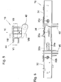
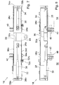
- FIGS. 5 to 14 four variants of transverse frame modules are shown, as they can be used in the context of the present invention. All four variants have a common basic structure, the first example of the in the FIGS. 5 to 8 illustrated first variant, namely the example of the heavy-duty vehicle 10 of the FIGS. 1 to 4 to be explained at both longitudinal ends used transverse frame modules 16, 18, before then on the specific additional features of the four variants will be discussed.
- the transverse frame module 16 comprises a central transverse frame portion 30 having a central portion 30a and two side portions 30b and 30c and two lateral transverse frame portions 32, 34 which engage around the side portions 30b and 30c of the central transverse frame portion 30 and are slidable relative thereto to permit the change in length of the transverse frame module 16 are.
- the central portion 30a is formed by that portion of the central transverse frame portion 30 which, when the lateral transverse frame portions 32, 34 are fully pushed onto the central central portion 30, is not covered by the lateral transverse frame portions 32, 34.
- the central transverse frame part 30 and the lateral transverse frame members 32, 34 are each formed as a hollow profile elements with a rectangular or square profile cross-section. This results in a robust construction of the cross-frame module, so that the heavy-duty vehicle 10 has the stability required for heavy-load transport.
- two force devices 36 and 38 are arranged, each of which is associated with one of the lateral transverse frame members 32, 34. That in the FIGS. 7 and 8
- the right end 36a of the left strength device 36 is fixed to the central transverse frame part 30, while its left end 36b is fixed to an end wall 32a of the left lateral cross frame part 32.
- the left end 38a of the right strength device 38 is attached to the central transverse frame portion 30, while its right end 36b is secured to an end wall 34a of the right lateral transverse frame portion 34.
- a thickness-reinforced portion 30d into which a plurality of through-holes 30e are inserted.
- a bolt 32b is engaged, which is held on the associated lateral transverse frame part 32 and biased by a spring 32c into engagement with the through hole 30e.
- the engagement of the bolt 32b in the hole 30e must be canceled.
- the length change by means of the force device 36 and finally, the bolt 32b in the new length adjustment corresponding hole 30e.
- the transverse frame module 16 can be blocked in the new length setting, so that when driving not the risk of undesirable change the vehicle width exists and an exact width arrangement is achieved, can be adjusted to the steering exactly adjusted.
- transverse frame modules have on at least one of their sides, ie on their seen in the direction of travel F front or rear side, via coupling elements 40, as they are also present at the longitudinal ends of conventional vehicle modules 12, 14, to these with other vehicle modules to one to be able to connect longer complete vehicle.
- the in FIG. 8 left coupling elements 40 and the corresponding trained and in FIG. 8 dashed lines indicated mating coupling elements of the left vehicle module 12 into each other
- the in FIG. 8 right coupling elements 40 and the corresponding trained and in FIG. 8 dashed lines indicated mating coupling elements of the right vehicle module 14 into each other.
- This engagement is then secured by also indicated by dashed lines securing bolt 42.
- the transverse frame module 16 is bolted to the vehicle modules 12 and 14 also adjacent to the upper edge of the transverse frame module 16 adjacent to a downward tilting of the cross-frame module 16 to prevent.
- the stability of the heavy vehicle 10 and the transmission of tensile and shear forces during the transport of the load is almost completely taken over by the coupling elements 40, their mating coupling elements and the securing bolt 42.
- transverse frame module 16 in addition to the basic structure described so far on its front side further coupling elements 44 on which serve for connection to a drawbar assembly 28, as in FIG. 15 is shown.
- the drawbar assembly 28 includes a drawbar 46, which is pivotally mounted to the transverse frame module 16 about a substantially vertical axis X by means of an axle bolt 48 which also passes through the openings of the coupling elements 44 of the transverse frame module 16. About the drawbar 46 and the axle 48, the tensile forces occurring during transport are introduced into the heavy vehicle 10.
- a Lenkwinkelweiter effetselement 50 is arranged, which is also mounted pivotably about the axis X, wherein the Lenkwinkelweiter effetselement 50 is also pivotable relative to the drawbar 46.
- a bolt 52 arranged on the drawbar 46 which engages in one of a plurality of depressions 50a of the steering angle relay element 50, various relative pivoting positions of the drawbar 46 and the steering angle-passing element 50 can be fixed.
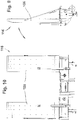
- transverse frame module 18 which, as already mentioned above, is identical to the transverse frame module 16, but by 180 ° is arranged at the rear end of the heavy-duty vehicle 10, at the rear end of the heavy-duty vehicle 10 also in the FIGS. 9 and 10 illustrated transverse frame module 116 are arranged.
- the structure of the transverse frame module 116 corresponds to that of the transverse frame module 16 of FIG FIGS. 5 to 8 , Therefore, the cross frame module 116 will not be described here in this regard. Rather, reference is made in full to the description of the transverse frame module 16 in this respect.
- the transverse frame module 116 differs from the transverse frame module 16 only in that on the side on which the transverse frame module 16, the coupling elements 44 are arranged for the attachment of drawbar assembly 28, ramps 156 for a vehicle to be transported on the heavy vehicle 10 are pivotally mounted.
- transverse frame module 16 (or rotated by 180 °: 18) can at the rear end of the heavy vehicle 10 also in the FIGS. 11 and 12 illustrated transverse frame module 216 are arranged.
- the structure of the transverse frame module 216 corresponds to that of the transverse frame module 16 of FIG FIGS. 5 to 8 , Therefore, the cross frame module 216 will not be described here in this regard. Rather, reference is made in full to the description of the transverse frame module 16 in this respect.
- the transverse frame module 216 differs from the transverse frame module 16 only in that on the side on which the transverse frame module 16, the coupling elements 44 are arranged for the attachment of the drawbar assembly 28, coupling elements 240 'are arranged, which are identical to those for connection to the Vehicle modules 12, 14 serving coupling elements 240.
- the cross-frame module 216 on both its front and on its rear side with Vehicle modules are connected. It is therefore suitable for use as an intermediate transverse frame module, if you want to put together a longer width adjustable heavy duty vehicle, for example, the in FIG. 16 illustrated heavy duty vehicle 410.
- transverse frame module 316 can at the rear end of the heavy vehicle 10 also in the FIGS. 13 and 14 shown transverse frame module 316 are arranged.
- the structure of the transverse frame module 316 corresponds to that of the transverse frame module 16 of FIG FIGS. 5 to 8 , Therefore, the cross frame module 316 will not be described here any more. Rather, reference is made in full to the description of the transverse frame module 16 in this respect.
- the transverse frame module 316 differs from the transverse frame module 16 only in that on the side on which the transverse elements 16 the coupling elements 44 are arranged for the attachment of the drawbar assembly 28, a connection device 358 for fixing a width-adjustable in the vehicle width direction B module 360, For example, a drive device for the heavy vehicle 10 or 410.
Landscapes
- Engineering & Computer Science (AREA)
- Transportation (AREA)
- Mechanical Engineering (AREA)
- Chemical & Material Sciences (AREA)
- Combustion & Propulsion (AREA)
- Body Structure For Vehicles (AREA)
- Automatic Cycles, And Cycles In General (AREA)
Claims (15)
- Véhicule poids lourd modulaire (10), comprenant :un module côté gauche (12) doté d'un élément de charpente allongé côté gauche (20) s'étendant dans le sens de la longueur du véhicule (L), auquel au moins deux groupes essieux côté gauche (22) sont agencés l'un derrière l'autre dans le sens de la longueur du véhicule (L),un module côté droit (14), conçu séparé de ce qui précède, doté d'un élément de charpente allongé côté droit (24) s'étendant dans le sens de la longueur du véhicule (L), auquel au moins deux groupes essieux côté droit (26) sont agencés l'un derrière l'autre dans le sens de la longueur du véhicule (L), etdeux unités de raccordement s'étendant dans le sens de la largeur du véhicule (B), dont une extrémité libre est raccordée à l'élément de charpente allongé côté gauche (20) et dont l'autre extrémité libre est raccordée à l'élément de charpente allongé côté droit (24),dans lequel les deux unités de raccordement sont conçues comme des modules de châssis réglables en longueur (16, 18 ; 116 ; 216 ; 316), lesquels sont conçus pour être séparés aussi bien de l'élément de charpente allongé côté gauche (20) que de l'élément de charpente allongé côté droit (24), etdans lequel qu'un premier de ces modules de châssis (16) est fixé de manière détachable à l'une des extrémités longues des deux éléments de charpente allongés (20, 24) et l'autre module de châssis (18) est fixé de manière détachable à l'autre extrémité longue des deux éléments de charpente allongés (20, 24),caractérisé en ce que les modules côté gauche et côté droit sont conçus avec leurs éléments de charpente droit et gauche s'étendant dans le sens de la longueur du véhicule pour être dépourvus d'éléments de fonction nécessaires pour la variabilité de la longueur.
- Véhicule poids lourd selon la revendication 1, caractérisé en ce qu'au moins un module de châssis (16, 18 ; 116 ; 216 ; 316) comprend des parties de châssis (30, 32, 34) s'emboîtant l'une dans l'autre de manière télescopique et entourant un espace creux, dans lequel au moins un appareil de puissance (36, 38) opérant la variation de longueur du module de châssis est agencé dans l'espace creux.
- Véhicule poids lourd selon la revendication 1 ou 2, caractérisé en ce qu'au moins un module de châssis (16, 18 ; 116 ; 216 ; 316) comprend une partie de châssis centrale (30) dotée de deux sections latérales (30b, 30c) ainsi que deux parties de châssis latérales (32, 34) qui entourent les sections latérales (30b, 30c) de la partie de châssis centrale (30) et peuvent coulisser par rapport à celles-ci.
- Véhicule poids lourd selon la revendication 3, caractérisé en ce qu'une section médiane (30a) est prévue entre les deux sections latérales (30b, 30c) de la partie de châssis centrale (30), conçue de préférence d'une pièce avec les deux sections latérales (30b, 30c).
- Véhicule poids lourd selon la revendication 3 ou 4, caractérisé en ce qu'au moins un élément de fonction (40 ; 156 ; 240 ; 240') peut être agencé aux deux parties de châssis latérales (32, 34) et est ajusté également dans le sens de la largeur (B) du véhicule lors d'une modification de la largeur du véhicule.
- Véhicule poids lourd selon la revendication 5, caractérisé en ce que l'au moins un élément de fonction, lequel est ajusté également dans le sens de la largeur (B) du véhicule lors d'une modification de la largeur du véhicule, comprend au moins un élément de couplage (40 ; 240) pour accoupler le module de châssis (16 ; 216) aux modules de véhicules côté gauche et côté droit (12, 14) et/ou comprend au moins un élément de couplage (240') pour accoupler le module de châssis comme élément intermédiaire entre plusieurs modules de véhicules (12, 14) agencés l'un derrière l'autre lors de l'assemblage d'un véhicule poids lourd modulaire, disposant dans le sens de la longueur du véhicule (L) de plusieurs modules de véhicule (12, 14) côté gauche et droit agencés l'un derrière l'autre et/ou comprend au moins une rampe repliable (156).
- Véhicule poids lourd selon l'une des revendications 4 à 6, caractérisé en ce qu'au moins un élément de fonction (44 ; 358) peut être agencé à la partie de châssis centrale (30a) et ne doit pas être ajusté dans le sens de la largeur (B) du véhicule lors d'un ajustage de la largeur du véhicule.
- Véhicule poids lourd selon la revendication 7, caractérisé en ce que l'au moins un élément de fonction qui ne doit pas être ajusté dans le sens de la largeur (B) du véhicule lors d'un ajustage de la largeur du véhicule, comprend au moins un élément de couplage (358) pour accoupler le module de châssis à un module de véhicule non-ajustable en largeur (360) et/ou au moins un élément de couplage (44) destiné au montage d'un groupe de barre de remorquage (28).
- Véhicule poids lourd selon l'une des revendications 1 à 8, caractérisé en ce qu'au moins un module de châssis (16, 18 ; 116 ; 216 ; 316) peut être fixé de manière détachable à la surface avant de l'extrémité longitudinale respectivement ordonnée des deux éléments de charpente allongés (20, 24).
- Véhicule poids lourd selon l'une des revendications 2 à 9, caractérisé en ce que chaque partie de châssis latérale (32, 34) est ordonnée à un appareil de puissance séparé (36, 38), dont une extrémité s'engage avec la partie de châssis centrale (30) et dont l'autre extrémité s'engage avec la partie de châssis latérale (32, 34) respective.
- Véhicule poids lourd selon l'une des revendications 1 à 10, caractérisé en ce que l'au moins un module de châssis (16, 18 ; 116 ; 216 ; 316) comporte dans une section essentiellement orthogonale au sens de la largeur du véhicule (B) un profil rectangulaire ou carré.
- Véhicule poids lourd selon l'une des revendications 3 à 11, caractérisé en ce que les parties de châssis latérales (32, 34) et les sections latérales (30b, 30c) de la partie de châssis centrale (30) s'y rattachant respectivement sont raccordables rigidement l'une à l'autre de manière détachable.
- Véhicule poids lourd selon l'une des revendications 3 à 12, caractérisé en ce qu'est prévu un affichage indiquant la position relative de la partie de châssis latérale (32, 34) et de la section latérale (30b, 30c) de la partie de châssis centrale (30) s'y rattachant.
- Véhicule poids lourd selon l'une des revendications 1 à 13, caractérisé en ce qu'est prévu un élément de transmission de l'angle de braquage (50), pouvant pivoter relativement à la barre de remorquage (46) et raccordable de manière détachable à la barre de remorquage dans au moins une position de pivotement relatif.
- Véhicule poids lourd selon la revendication 14, caractérisé en ce que l'axe (X) autour duquel l'élément de transmission de l'angle de braquage (50) peut pivoter relativement à la barre de remorquage (46), est identique à l'axe (X) autour duquel la barre de remorquage (46) peut pivoter relativement au véhicule poids lourd modulaire.
Applications Claiming Priority (2)
| Application Number | Priority Date | Filing Date | Title |
|---|---|---|---|
| DE102014202726.8A DE102014202726A1 (de) | 2014-02-14 | 2014-02-14 | Breitenverstellbares modulares Schwerlastfahrzeug und Querrahmenmodul für ein derartiges Schwerlastfahrzeug |
| PCT/EP2015/052847 WO2015121291A1 (fr) | 2014-02-14 | 2015-02-11 | Poids lourd modulaire ajustable en largeur et module de châssis transversal pour un poids lourd de ce type |
Publications (2)
| Publication Number | Publication Date |
|---|---|
| EP3105109A1 EP3105109A1 (fr) | 2016-12-21 |
| EP3105109B1 true EP3105109B1 (fr) | 2019-02-20 |
Family
ID=52574121
Family Applications (1)
| Application Number | Title | Priority Date | Filing Date |
|---|---|---|---|
| EP15705948.6A Active EP3105109B1 (fr) | 2014-02-14 | 2015-02-11 | Poids lourd modulaire ajustable en largeur et module de châssis transversal pour un poids lourd de ce type |
Country Status (7)
| Country | Link |
|---|---|
| US (1) | US9849927B2 (fr) |
| EP (1) | EP3105109B1 (fr) |
| AU (1) | AU2015217689B2 (fr) |
| CA (1) | CA2939028C (fr) |
| DE (1) | DE102014202726A1 (fr) |
| WO (1) | WO2015121291A1 (fr) |
| ZA (1) | ZA201605371B (fr) |
Families Citing this family (6)
| Publication number | Priority date | Publication date | Assignee | Title |
|---|---|---|---|---|
| DE202013104703U1 (de) * | 2013-10-18 | 2014-04-16 | J.G.B.D. Consult Sprl | Schwerlastmodulfahrzeug |
| EP2927049B1 (fr) * | 2014-04-02 | 2017-08-30 | J.G.B.D. Consult SPRL | Tubes d'extension modulaires |
| US9834263B1 (en) * | 2016-05-19 | 2017-12-05 | Mammoet Usa South, Inc. | Expanding self propelled modular transport trailers |
| US11241994B2 (en) | 2019-10-10 | 2022-02-08 | Joseph Lee Pollon | Expandable vehicle |
| USD952981S1 (en) | 2020-04-30 | 2022-05-24 | Rubbermaid Commercial Products Llc | Waste receptacle with a handle |
| US11873161B2 (en) | 2020-04-30 | 2024-01-16 | Rubbermaid Commercial Products Llc | Waste receptacles |
Family Cites Families (12)
| Publication number | Priority date | Publication date | Assignee | Title |
|---|---|---|---|---|
| US3712398A (en) * | 1970-03-19 | 1973-01-23 | Orenstein & Koppel Ag | Hydraulically operable device for changing the track width of track-laying vehicles |
| US3698734A (en) * | 1971-02-22 | 1972-10-17 | Colin Anthony Drake | Trailers |
| FR2399351A1 (fr) * | 1977-08-02 | 1979-03-02 | France Nicolas | Perfectionnements aux vehicules tractes routiers de largeur reglable |
| DE8422387U1 (de) * | 1984-07-27 | 1986-04-17 | Goldhofer Fahrzeugwerk Gmbh & Co, 8940 Memmingen | Schwerlast-Anhängerfahrzeug |
| IT1285573B1 (it) * | 1996-02-29 | 1998-06-18 | Luigi Gallignani | Apparato per bloccaggio integrale delle parti mobili di struttura previste per la variazione della carreggiata nei sottocarri |
| WO2000064700A1 (fr) * | 1999-04-27 | 2000-11-02 | Strang International Pty Limited | Remorque pour charges modulaires ou unitisees |
| US6206126B1 (en) * | 2000-04-13 | 2001-03-27 | Thiermann Industries, Inc. | Carrier for lifting devices having variable width track |
| DE10200175A1 (de) | 2002-01-04 | 2003-07-24 | Bauer Maschinen Gmbh | Raupenfahrwerk |
| AU2009200341A1 (en) * | 2009-01-30 | 2010-08-19 | Colron Industries Pty Ltd | Trailer |
| WO2010094935A1 (fr) * | 2009-02-20 | 2010-08-26 | Terry Deakin | Remorque extensible latéralement pour manipuler des charges telles que des conteneurs |
| CA2892743C (fr) * | 2012-12-12 | 2020-03-31 | Scheuerle Fahrzeugfabrik Gmbh | Vehicule de transport a largeur et a voie variables, pourvu d'au moins un essieu directeur |
| DE202012011898U1 (de) * | 2012-12-12 | 2013-03-04 | Scheuerle Fahrzeugfabrik Gmbh | Transportfahrzeug mit variabler Breite und Spurweite und mindestens einer Lenkachse |
-
2014
- 2014-02-14 DE DE102014202726.8A patent/DE102014202726A1/de not_active Withdrawn
-
2015
- 2015-02-11 WO PCT/EP2015/052847 patent/WO2015121291A1/fr not_active Ceased
- 2015-02-11 CA CA2939028A patent/CA2939028C/fr active Active
- 2015-02-11 AU AU2015217689A patent/AU2015217689B2/en active Active
- 2015-02-11 EP EP15705948.6A patent/EP3105109B1/fr active Active
- 2015-02-11 US US15/118,555 patent/US9849927B2/en active Active
-
2016
- 2016-08-04 ZA ZA2016/05371A patent/ZA201605371B/en unknown
Non-Patent Citations (1)
| Title |
|---|
| None * |
Also Published As
| Publication number | Publication date |
|---|---|
| ZA201605371B (en) | 2017-08-30 |
| WO2015121291A1 (fr) | 2015-08-20 |
| EP3105109A1 (fr) | 2016-12-21 |
| AU2015217689A1 (en) | 2016-09-01 |
| US20170050692A1 (en) | 2017-02-23 |
| CA2939028C (fr) | 2020-01-21 |
| CA2939028A1 (fr) | 2015-08-20 |
| DE102014202726A1 (de) | 2015-08-20 |
| AU2015217689B2 (en) | 2018-10-11 |
| US9849927B2 (en) | 2017-12-26 |
Similar Documents
| Publication | Publication Date | Title |
|---|---|---|
| EP3105109B1 (fr) | Poids lourd modulaire ajustable en largeur et module de châssis transversal pour un poids lourd de ce type | |
| DE202013104703U1 (de) | Schwerlastmodulfahrzeug | |
| EP2002999A1 (fr) | Véhicule tracteur réalisé en forme de bus avec une remorque pour le transport de voyageurs | |
| EP3160828B1 (fr) | Véhicule de transport, notamment véhicule de transport automoteur, de largeur variable | |
| DE102014009036B4 (de) | Transportfahrzeug, insbesondere selbstangetriebenes Transportfahrzeug, mit variabler Breite | |
| EP2199247A2 (fr) | Liaison rotative | |
| DE19813189A1 (de) | Anhängefahrzeug | |
| DE202014005055U1 (de) | Transportfahrzeug, insbesondere selbstangetriebenes Transportfahrzeug, mit variabler Breite | |
| DE102013107914A1 (de) | Trageinrichtung | |
| EP3549417A1 (fr) | Ensemble de bras de levage pour un relevage hydraulic trois points d'un tracteur ou d'un autre engin de travail agricole ainsi que relevage hydraulic trois points | |
| EP2457752B1 (fr) | Dispositif d'embrayage et dispositif d'attelage pour véhicules tracteurs | |
| DE102015201365A1 (de) | Unterfahrschutzeinrichtung | |
| DE19757917A1 (de) | Eisenbahnfahrzeug mit Pufferbohle, die befähigt ist, sich kontrolliert zu verformen, wenn sie einem relevanten Druck ausgesetzt wird | |
| DE102014008720B4 (de) | Schwerlastfahrzeug mit Staplerfunktion | |
| DE2648324A1 (de) | Fahrgestell fuer ein fahrzeug | |
| EP0600500B1 (fr) | Aménagement d'un attelage de remorque pour véhicule | |
| EP3094527B1 (fr) | Béquille de sécurité | |
| EP3098093A1 (fr) | Fourche de traction pour une remorque | |
| EP1621450B1 (fr) | Véhicule pour le transport de charges lourdes | |
| DE202020106249U1 (de) | Unterfahrschutz sowie Unterfahrschutzsystem für ein Fahrzeug sowie entsprechend ausgestattetes Fahrzeug | |
| EP1067038A1 (fr) | Remorque | |
| DE4339670C2 (de) | Verriegelungssystem für Wechselgeräte zur Verwendung bei Lastkraftwagen sowie Element zur Verwendung bei einem derartigen System | |
| EP1839942A2 (fr) | Arrière de camion avec rampe de chargement | |
| EP3222464A1 (fr) | Système de cadre pour carrosseries de véhicules automobiles | |
| DE202023107552U1 (de) | Anhänger zum Transportieren von Containern |
Legal Events
| Date | Code | Title | Description |
|---|---|---|---|
| PUAI | Public reference made under article 153(3) epc to a published international application that has entered the european phase |
Free format text: ORIGINAL CODE: 0009012 |
|
| STAA | Information on the status of an ep patent application or granted ep patent |
Free format text: STATUS: REQUEST FOR EXAMINATION WAS MADE |
|
| 17P | Request for examination filed |
Effective date: 20160805 |
|
| AK | Designated contracting states |
Kind code of ref document: A1 Designated state(s): AL AT BE BG CH CY CZ DE DK EE ES FI FR GB GR HR HU IE IS IT LI LT LU LV MC MK MT NL NO PL PT RO RS SE SI SK SM TR |
|
| AX | Request for extension of the european patent |
Extension state: BA ME |
|
| DAX | Request for extension of the european patent (deleted) | ||
| STAA | Information on the status of an ep patent application or granted ep patent |
Free format text: STATUS: EXAMINATION IS IN PROGRESS |
|
| 17Q | First examination report despatched |
Effective date: 20171114 |
|
| GRAP | Despatch of communication of intention to grant a patent |
Free format text: ORIGINAL CODE: EPIDOSNIGR1 |
|
| STAA | Information on the status of an ep patent application or granted ep patent |
Free format text: STATUS: GRANT OF PATENT IS INTENDED |
|
| INTG | Intention to grant announced |
Effective date: 20180801 |
|
| GRAS | Grant fee paid |
Free format text: ORIGINAL CODE: EPIDOSNIGR3 |
|
| GRAJ | Information related to disapproval of communication of intention to grant by the applicant or resumption of examination proceedings by the epo deleted |
Free format text: ORIGINAL CODE: EPIDOSDIGR1 |
|
| GRAL | Information related to payment of fee for publishing/printing deleted |
Free format text: ORIGINAL CODE: EPIDOSDIGR3 |
|
| STAA | Information on the status of an ep patent application or granted ep patent |
Free format text: STATUS: EXAMINATION IS IN PROGRESS |
|
| GRAR | Information related to intention to grant a patent recorded |
Free format text: ORIGINAL CODE: EPIDOSNIGR71 |
|
| STAA | Information on the status of an ep patent application or granted ep patent |
Free format text: STATUS: GRANT OF PATENT IS INTENDED |
|
| GRAA | (expected) grant |
Free format text: ORIGINAL CODE: 0009210 |
|
| STAA | Information on the status of an ep patent application or granted ep patent |
Free format text: STATUS: THE PATENT HAS BEEN GRANTED |
|
| INTC | Intention to grant announced (deleted) | ||
| INTG | Intention to grant announced |
Effective date: 20190110 |
|
| AK | Designated contracting states |
Kind code of ref document: B1 Designated state(s): AL AT BE BG CH CY CZ DE DK EE ES FI FR GB GR HR HU IE IS IT LI LT LU LV MC MK MT NL NO PL PT RO RS SE SI SK SM TR |
|
| REG | Reference to a national code |
Ref country code: GB Ref legal event code: FG4D Free format text: NOT ENGLISH |
|
| REG | Reference to a national code |
Ref country code: CH Ref legal event code: EP |
|
| REG | Reference to a national code |
Ref country code: DE Ref legal event code: R096 Ref document number: 502015008010 Country of ref document: DE |
|
| REG | Reference to a national code |
Ref country code: AT Ref legal event code: REF Ref document number: 1097800 Country of ref document: AT Kind code of ref document: T Effective date: 20190315 |
|
| REG | Reference to a national code |
Ref country code: IE Ref legal event code: FG4D Free format text: LANGUAGE OF EP DOCUMENT: GERMAN |
|
| REG | Reference to a national code |
Ref country code: NL Ref legal event code: MP Effective date: 20190220 |
|
| REG | Reference to a national code |
Ref country code: LT Ref legal event code: MG4D |
|
| PG25 | Lapsed in a contracting state [announced via postgrant information from national office to epo] |
Ref country code: NL Free format text: LAPSE BECAUSE OF FAILURE TO SUBMIT A TRANSLATION OF THE DESCRIPTION OR TO PAY THE FEE WITHIN THE PRESCRIBED TIME-LIMIT Effective date: 20190220 Ref country code: LT Free format text: LAPSE BECAUSE OF FAILURE TO SUBMIT A TRANSLATION OF THE DESCRIPTION OR TO PAY THE FEE WITHIN THE PRESCRIBED TIME-LIMIT Effective date: 20190220 Ref country code: FI Free format text: LAPSE BECAUSE OF FAILURE TO SUBMIT A TRANSLATION OF THE DESCRIPTION OR TO PAY THE FEE WITHIN THE PRESCRIBED TIME-LIMIT Effective date: 20190220 Ref country code: SE Free format text: LAPSE BECAUSE OF FAILURE TO SUBMIT A TRANSLATION OF THE DESCRIPTION OR TO PAY THE FEE WITHIN THE PRESCRIBED TIME-LIMIT Effective date: 20190220 Ref country code: PT Free format text: LAPSE BECAUSE OF FAILURE TO SUBMIT A TRANSLATION OF THE DESCRIPTION OR TO PAY THE FEE WITHIN THE PRESCRIBED TIME-LIMIT Effective date: 20190620 Ref country code: NO Free format text: LAPSE BECAUSE OF FAILURE TO SUBMIT A TRANSLATION OF THE DESCRIPTION OR TO PAY THE FEE WITHIN THE PRESCRIBED TIME-LIMIT Effective date: 20190520 |
|
| PG25 | Lapsed in a contracting state [announced via postgrant information from national office to epo] |
Ref country code: HR Free format text: LAPSE BECAUSE OF FAILURE TO SUBMIT A TRANSLATION OF THE DESCRIPTION OR TO PAY THE FEE WITHIN THE PRESCRIBED TIME-LIMIT Effective date: 20190220 Ref country code: RS Free format text: LAPSE BECAUSE OF FAILURE TO SUBMIT A TRANSLATION OF THE DESCRIPTION OR TO PAY THE FEE WITHIN THE PRESCRIBED TIME-LIMIT Effective date: 20190220 Ref country code: BG Free format text: LAPSE BECAUSE OF FAILURE TO SUBMIT A TRANSLATION OF THE DESCRIPTION OR TO PAY THE FEE WITHIN THE PRESCRIBED TIME-LIMIT Effective date: 20190520 Ref country code: GR Free format text: LAPSE BECAUSE OF FAILURE TO SUBMIT A TRANSLATION OF THE DESCRIPTION OR TO PAY THE FEE WITHIN THE PRESCRIBED TIME-LIMIT Effective date: 20190521 Ref country code: LV Free format text: LAPSE BECAUSE OF FAILURE TO SUBMIT A TRANSLATION OF THE DESCRIPTION OR TO PAY THE FEE WITHIN THE PRESCRIBED TIME-LIMIT Effective date: 20190220 Ref country code: IS Free format text: LAPSE BECAUSE OF FAILURE TO SUBMIT A TRANSLATION OF THE DESCRIPTION OR TO PAY THE FEE WITHIN THE PRESCRIBED TIME-LIMIT Effective date: 20190620 |
|
| PG25 | Lapsed in a contracting state [announced via postgrant information from national office to epo] |
Ref country code: EE Free format text: LAPSE BECAUSE OF FAILURE TO SUBMIT A TRANSLATION OF THE DESCRIPTION OR TO PAY THE FEE WITHIN THE PRESCRIBED TIME-LIMIT Effective date: 20190220 Ref country code: SK Free format text: LAPSE BECAUSE OF FAILURE TO SUBMIT A TRANSLATION OF THE DESCRIPTION OR TO PAY THE FEE WITHIN THE PRESCRIBED TIME-LIMIT Effective date: 20190220 Ref country code: RO Free format text: LAPSE BECAUSE OF FAILURE TO SUBMIT A TRANSLATION OF THE DESCRIPTION OR TO PAY THE FEE WITHIN THE PRESCRIBED TIME-LIMIT Effective date: 20190220 Ref country code: CZ Free format text: LAPSE BECAUSE OF FAILURE TO SUBMIT A TRANSLATION OF THE DESCRIPTION OR TO PAY THE FEE WITHIN THE PRESCRIBED TIME-LIMIT Effective date: 20190220 Ref country code: ES Free format text: LAPSE BECAUSE OF FAILURE TO SUBMIT A TRANSLATION OF THE DESCRIPTION OR TO PAY THE FEE WITHIN THE PRESCRIBED TIME-LIMIT Effective date: 20190220 Ref country code: AL Free format text: LAPSE BECAUSE OF FAILURE TO SUBMIT A TRANSLATION OF THE DESCRIPTION OR TO PAY THE FEE WITHIN THE PRESCRIBED TIME-LIMIT Effective date: 20190220 Ref country code: DK Free format text: LAPSE BECAUSE OF FAILURE TO SUBMIT A TRANSLATION OF THE DESCRIPTION OR TO PAY THE FEE WITHIN THE PRESCRIBED TIME-LIMIT Effective date: 20190220 |
|
| REG | Reference to a national code |
Ref country code: DE Ref legal event code: R097 Ref document number: 502015008010 Country of ref document: DE |
|
| PG25 | Lapsed in a contracting state [announced via postgrant information from national office to epo] |
Ref country code: PL Free format text: LAPSE BECAUSE OF FAILURE TO SUBMIT A TRANSLATION OF THE DESCRIPTION OR TO PAY THE FEE WITHIN THE PRESCRIBED TIME-LIMIT Effective date: 20190220 Ref country code: SM Free format text: LAPSE BECAUSE OF FAILURE TO SUBMIT A TRANSLATION OF THE DESCRIPTION OR TO PAY THE FEE WITHIN THE PRESCRIBED TIME-LIMIT Effective date: 20190220 |
|
| PLBE | No opposition filed within time limit |
Free format text: ORIGINAL CODE: 0009261 |
|
| STAA | Information on the status of an ep patent application or granted ep patent |
Free format text: STATUS: NO OPPOSITION FILED WITHIN TIME LIMIT |
|
| 26N | No opposition filed |
Effective date: 20191121 |
|
| PG25 | Lapsed in a contracting state [announced via postgrant information from national office to epo] |
Ref country code: SI Free format text: LAPSE BECAUSE OF FAILURE TO SUBMIT A TRANSLATION OF THE DESCRIPTION OR TO PAY THE FEE WITHIN THE PRESCRIBED TIME-LIMIT Effective date: 20190220 |
|
| PG25 | Lapsed in a contracting state [announced via postgrant information from national office to epo] |
Ref country code: TR Free format text: LAPSE BECAUSE OF FAILURE TO SUBMIT A TRANSLATION OF THE DESCRIPTION OR TO PAY THE FEE WITHIN THE PRESCRIBED TIME-LIMIT Effective date: 20190220 |
|
| PGFP | Annual fee paid to national office [announced via postgrant information from national office to epo] |
Ref country code: DE Payment date: 20200228 Year of fee payment: 6 Ref country code: IT Payment date: 20200228 Year of fee payment: 6 |
|
| REG | Reference to a national code |
Ref country code: CH Ref legal event code: PL |
|
| GBPC | Gb: european patent ceased through non-payment of renewal fee |
Effective date: 20200211 |
|
| PG25 | Lapsed in a contracting state [announced via postgrant information from national office to epo] |
Ref country code: LU Free format text: LAPSE BECAUSE OF NON-PAYMENT OF DUE FEES Effective date: 20200211 Ref country code: MC Free format text: LAPSE BECAUSE OF FAILURE TO SUBMIT A TRANSLATION OF THE DESCRIPTION OR TO PAY THE FEE WITHIN THE PRESCRIBED TIME-LIMIT Effective date: 20190220 |
|
| PG25 | Lapsed in a contracting state [announced via postgrant information from national office to epo] |
Ref country code: LI Free format text: LAPSE BECAUSE OF NON-PAYMENT OF DUE FEES Effective date: 20200229 Ref country code: CH Free format text: LAPSE BECAUSE OF NON-PAYMENT OF DUE FEES Effective date: 20200229 |
|
| PG25 | Lapsed in a contracting state [announced via postgrant information from national office to epo] |
Ref country code: IE Free format text: LAPSE BECAUSE OF NON-PAYMENT OF DUE FEES Effective date: 20200211 Ref country code: FR Free format text: LAPSE BECAUSE OF NON-PAYMENT OF DUE FEES Effective date: 20200229 Ref country code: GB Free format text: LAPSE BECAUSE OF NON-PAYMENT OF DUE FEES Effective date: 20200211 |
|
| REG | Reference to a national code |
Ref country code: AT Ref legal event code: MM01 Ref document number: 1097800 Country of ref document: AT Kind code of ref document: T Effective date: 20200211 |
|
| PG25 | Lapsed in a contracting state [announced via postgrant information from national office to epo] |
Ref country code: AT Free format text: LAPSE BECAUSE OF NON-PAYMENT OF DUE FEES Effective date: 20200211 |
|
| REG | Reference to a national code |
Ref country code: DE Ref legal event code: R119 Ref document number: 502015008010 Country of ref document: DE |
|
| PG25 | Lapsed in a contracting state [announced via postgrant information from national office to epo] |
Ref country code: DE Free format text: LAPSE BECAUSE OF NON-PAYMENT OF DUE FEES Effective date: 20210901 |
|
| PG25 | Lapsed in a contracting state [announced via postgrant information from national office to epo] |
Ref country code: IT Free format text: LAPSE BECAUSE OF NON-PAYMENT OF DUE FEES Effective date: 20210211 |
|
| PG25 | Lapsed in a contracting state [announced via postgrant information from national office to epo] |
Ref country code: MT Free format text: LAPSE BECAUSE OF FAILURE TO SUBMIT A TRANSLATION OF THE DESCRIPTION OR TO PAY THE FEE WITHIN THE PRESCRIBED TIME-LIMIT Effective date: 20190220 Ref country code: CY Free format text: LAPSE BECAUSE OF FAILURE TO SUBMIT A TRANSLATION OF THE DESCRIPTION OR TO PAY THE FEE WITHIN THE PRESCRIBED TIME-LIMIT Effective date: 20190220 |
|
| PG25 | Lapsed in a contracting state [announced via postgrant information from national office to epo] |
Ref country code: MK Free format text: LAPSE BECAUSE OF FAILURE TO SUBMIT A TRANSLATION OF THE DESCRIPTION OR TO PAY THE FEE WITHIN THE PRESCRIBED TIME-LIMIT Effective date: 20190220 |
|
| PGFP | Annual fee paid to national office [announced via postgrant information from national office to epo] |
Ref country code: BE Payment date: 20230216 Year of fee payment: 9 |
|
| REG | Reference to a national code |
Ref country code: BE Ref legal event code: MM Effective date: 20240229 |
|
| PG25 | Lapsed in a contracting state [announced via postgrant information from national office to epo] |
Ref country code: BE Free format text: LAPSE BECAUSE OF NON-PAYMENT OF DUE FEES Effective date: 20240229 |
|
| PG25 | Lapsed in a contracting state [announced via postgrant information from national office to epo] |
Ref country code: BE Free format text: LAPSE BECAUSE OF NON-PAYMENT OF DUE FEES Effective date: 20240229 |