EP3105186B1 - Dispositif pour disperser a la source les emissions d'effluents gazeux nauseabonds - Google Patents
Dispositif pour disperser a la source les emissions d'effluents gazeux nauseabonds Download PDFInfo
- Publication number
- EP3105186B1 EP3105186B1 EP15709747.8A EP15709747A EP3105186B1 EP 3105186 B1 EP3105186 B1 EP 3105186B1 EP 15709747 A EP15709747 A EP 15709747A EP 3105186 B1 EP3105186 B1 EP 3105186B1
- Authority
- EP
- European Patent Office
- Prior art keywords
- injectors
- odor
- source
- foul
- air
- Prior art date
- Legal status (The legal status is an assumption and is not a legal conclusion. Google has not performed a legal analysis and makes no representation as to the accuracy of the status listed.)
- Active
Links
Images

Classifications
-
- F—MECHANICAL ENGINEERING; LIGHTING; HEATING; WEAPONS; BLASTING
- F23—COMBUSTION APPARATUS; COMBUSTION PROCESSES
- F23L—SUPPLYING AIR OR NON-COMBUSTIBLE LIQUIDS OR GASES TO COMBUSTION APPARATUS IN GENERAL ; VALVES OR DAMPERS SPECIALLY ADAPTED FOR CONTROLLING AIR SUPPLY OR DRAUGHT IN COMBUSTION APPARATUS; INDUCING DRAUGHT IN COMBUSTION APPARATUS; TOPS FOR CHIMNEYS OR VENTILATING SHAFTS; TERMINALS FOR FLUES
- F23L17/00—Inducing draught; Tops for chimneys or ventilating shafts; Terminals for flues
- F23L17/16—Induction apparatus, e.g. steam jet, acting on combustion products beyond the fire
-
- A—HUMAN NECESSITIES
- A61—MEDICAL OR VETERINARY SCIENCE; HYGIENE
- A61L—METHODS OR APPARATUS FOR STERILISING MATERIALS OR OBJECTS IN GENERAL; DISINFECTION, STERILISATION OR DEODORISATION OF AIR; CHEMICAL ASPECTS OF BANDAGES, DRESSINGS, ABSORBENT PADS OR SURGICAL ARTICLES; MATERIALS FOR BANDAGES, DRESSINGS, ABSORBENT PADS OR SURGICAL ARTICLES
- A61L9/00—Disinfection, sterilisation or deodorisation of air
- A61L9/14—Disinfection, sterilisation or deodorisation of air using sprayed or atomised substances including air-liquid contact processes
-
- B—PERFORMING OPERATIONS; TRANSPORTING
- B01—PHYSICAL OR CHEMICAL PROCESSES OR APPARATUS IN GENERAL
- B01D—SEPARATION
- B01D53/00—Separation of gases or vapours; Recovering vapours of volatile solvents from gases; Chemical or biological purification of waste gases, e.g. engine exhaust gases, smoke, fumes, flue gases, aerosols
-
- B—PERFORMING OPERATIONS; TRANSPORTING
- B01—PHYSICAL OR CHEMICAL PROCESSES OR APPARATUS IN GENERAL
- B01F—MIXING, e.g. DISSOLVING, EMULSIFYING OR DISPERSING
- B01F23/00—Mixing according to the phases to be mixed, e.g. dispersing or emulsifying
- B01F23/20—Mixing gases with liquids
- B01F23/21—Mixing gases with liquids by introducing liquids into gaseous media
- B01F23/213—Mixing gases with liquids by introducing liquids into gaseous media by spraying or atomising of the liquids
- B01F23/2132—Mixing gases with liquids by introducing liquids into gaseous media by spraying or atomising of the liquids using nozzles
- B01F23/21321—High pressure atomization, i.e. the liquid is atomized and sprayed by a jet at high pressure
-
- B—PERFORMING OPERATIONS; TRANSPORTING
- B01—PHYSICAL OR CHEMICAL PROCESSES OR APPARATUS IN GENERAL
- B01F—MIXING, e.g. DISSOLVING, EMULSIFYING OR DISPERSING
- B01F25/00—Flow mixers; Mixers for falling materials, e.g. solid particles
- B01F25/30—Injector mixers
-
- B—PERFORMING OPERATIONS; TRANSPORTING
- B05—SPRAYING OR ATOMISING IN GENERAL; APPLYING FLUENT MATERIALS TO SURFACES, IN GENERAL
- B05B—SPRAYING APPARATUS; ATOMISING APPARATUS; NOZZLES
- B05B12/00—Arrangements for controlling delivery; Arrangements for controlling the spray area
- B05B12/16—Arrangements for controlling delivery; Arrangements for controlling the spray area for controlling the spray area
- B05B12/18—Arrangements for controlling delivery; Arrangements for controlling the spray area for controlling the spray area using fluids, e.g. gas streams
-
- A—HUMAN NECESSITIES
- A61—MEDICAL OR VETERINARY SCIENCE; HYGIENE
- A61L—METHODS OR APPARATUS FOR STERILISING MATERIALS OR OBJECTS IN GENERAL; DISINFECTION, STERILISATION OR DEODORISATION OF AIR; CHEMICAL ASPECTS OF BANDAGES, DRESSINGS, ABSORBENT PADS OR SURGICAL ARTICLES; MATERIALS FOR BANDAGES, DRESSINGS, ABSORBENT PADS OR SURGICAL ARTICLES
- A61L2209/00—Aspects relating to disinfection, sterilisation or deodorisation of air
- A61L2209/10—Apparatus features
- A61L2209/11—Apparatus for controlling air treatment
- A61L2209/111—Sensor means, e.g. motion, brightness, scent, contaminant sensors
-
- A—HUMAN NECESSITIES
- A61—MEDICAL OR VETERINARY SCIENCE; HYGIENE
- A61L—METHODS OR APPARATUS FOR STERILISING MATERIALS OR OBJECTS IN GENERAL; DISINFECTION, STERILISATION OR DEODORISATION OF AIR; CHEMICAL ASPECTS OF BANDAGES, DRESSINGS, ABSORBENT PADS OR SURGICAL ARTICLES; MATERIALS FOR BANDAGES, DRESSINGS, ABSORBENT PADS OR SURGICAL ARTICLES
- A61L2209/00—Aspects relating to disinfection, sterilisation or deodorisation of air
- A61L2209/20—Method-related aspects
- A61L2209/21—Use of chemical compounds for treating air or the like
-
- A—HUMAN NECESSITIES
- A61—MEDICAL OR VETERINARY SCIENCE; HYGIENE
- A61L—METHODS OR APPARATUS FOR STERILISING MATERIALS OR OBJECTS IN GENERAL; DISINFECTION, STERILISATION OR DEODORISATION OF AIR; CHEMICAL ASPECTS OF BANDAGES, DRESSINGS, ABSORBENT PADS OR SURGICAL ARTICLES; MATERIALS FOR BANDAGES, DRESSINGS, ABSORBENT PADS OR SURGICAL ARTICLES
- A61L9/00—Disinfection, sterilisation or deodorisation of air
-
- B—PERFORMING OPERATIONS; TRANSPORTING
- B01—PHYSICAL OR CHEMICAL PROCESSES OR APPARATUS IN GENERAL
- B01F—MIXING, e.g. DISSOLVING, EMULSIFYING OR DISPERSING
- B01F2101/00—Mixing characterised by the nature of the mixed materials or by the application field
- B01F2101/54—Mixing liquid fragrances with air
-
- B—PERFORMING OPERATIONS; TRANSPORTING
- B08—CLEANING
- B08B—CLEANING IN GENERAL; PREVENTION OF FOULING IN GENERAL
- B08B2215/00—Preventing escape of dirt or fumes from the area where they are produced; Collecting or removing dirt or fumes from that area
- B08B2215/003—Preventing escape of dirt or fumes from the area where they are produced; Collecting or removing dirt or fumes from that area with the assistance of blowing nozzles
-
- F—MECHANICAL ENGINEERING; LIGHTING; HEATING; WEAPONS; BLASTING
- F23—COMBUSTION APPARATUS; COMBUSTION PROCESSES
- F23J—REMOVAL OR TREATMENT OF COMBUSTION PRODUCTS OR COMBUSTION RESIDUES; FLUES
- F23J2215/00—Preventing emissions
-
- F—MECHANICAL ENGINEERING; LIGHTING; HEATING; WEAPONS; BLASTING
- F23—COMBUSTION APPARATUS; COMBUSTION PROCESSES
- F23L—SUPPLYING AIR OR NON-COMBUSTIBLE LIQUIDS OR GASES TO COMBUSTION APPARATUS IN GENERAL ; VALVES OR DAMPERS SPECIALLY ADAPTED FOR CONTROLLING AIR SUPPLY OR DRAUGHT IN COMBUSTION APPARATUS; INDUCING DRAUGHT IN COMBUSTION APPARATUS; TOPS FOR CHIMNEYS OR VENTILATING SHAFTS; TERMINALS FOR FLUES
- F23L2700/00—Installations for increasing draught in chimneys; Specific draught control devices for locomotives
- F23L2700/001—Installations for increasing draught in chimneys
-
- Y—GENERAL TAGGING OF NEW TECHNOLOGICAL DEVELOPMENTS; GENERAL TAGGING OF CROSS-SECTIONAL TECHNOLOGIES SPANNING OVER SEVERAL SECTIONS OF THE IPC; TECHNICAL SUBJECTS COVERED BY FORMER USPC CROSS-REFERENCE ART COLLECTIONS [XRACs] AND DIGESTS
- Y02—TECHNOLOGIES OR APPLICATIONS FOR MITIGATION OR ADAPTATION AGAINST CLIMATE CHANGE
- Y02W—CLIMATE CHANGE MITIGATION TECHNOLOGIES RELATED TO WASTEWATER TREATMENT OR WASTE MANAGEMENT
- Y02W10/00—Technologies for wastewater treatment
- Y02W10/30—Wastewater or sewage treatment systems using renewable energies
- Y02W10/33—Wastewater or sewage treatment systems using renewable energies using wind energy
Definitions
- the invention relates to a source dispersing device for emissions of foul-smelling gaseous effluents, diffusely released by sources located close to the ground, in particular by wastewater treatment basins or any other activity which gives off odors.
- the gaseous effluents can be dispersed at a certain height in the atmosphere by chimneys.
- the height of the chimneys varies according to the nature and the composition of the gases, the regulations in force and the results of the study of dispersion of gaseous, particulate and smelly pollutants.
- the dispersion of gases in the environment is improved by increasing the stack height.
- a turbulent and sustained wind regime has the effect of mixing the gases with the ambient air and thus promoting the dispersion of pollutants.
- EP 2161446 describes a wind turbine which promotes the dispersion of gas in the atmosphere near a sewage treatment plant and which comprises a vertical mast equipped with a rotor with blades, the mast thus being able to be used for the evacuation of gas.
- WO 2010/044 055 proposed to improve and promote the dispersion of gases by providing at least one air or auxiliary gas injector installed near the outlet of a chimney and directed upwards so as to disperse the gases.
- Emissions can be diffuse and come from, for example, large basins of wastewater treatment plants, landfill sites, organic waste storage areas, organic matter ripening areas and similar facilities. Such installations are not necessarily open-air, and can be covered at least in part, but the gaseous effluents are no longer channeled to an outlet, including a chimney. It is no longer possible or difficult and expensive to capture the source of foul smelling, and a means used to fight against odors is to mask these odors by diffusing "white" products whose objective is to reduce the odor olfactory impact, covering odors.
- Such a means has a very limited efficiency because it acts only locally in the area of diffusion masking products.
- the molecules used are not completely neutral for the environment.
- electrochemical sensors In order to objectively evaluate the ambient odor rate, electrochemical sensors have been developed. Such sensors are positioned in areas of human presence to continuously measure the concentration of the most odorous molecules such as H 2 S, NH 3 , mercaptan. These sensors make it possible to convert chemical measurements into odor units that refer to human odor perception, and to indicate the current nuisance factor.
- the device comprises odor detectors distributed around the periphery of an installation comprising at least one source of foul odors, these detectors being arranged to communicate the results of their measurements to a measurement acquisition unit connected to a control unit which, according to the measurement results, activates at least one fan to supply at least one suitable sector of injectors.
- odor detectors distributed around the periphery of an installation comprising at least one source of foul odors, these detectors being arranged to communicate the results of their measurements to a measurement acquisition unit connected to a control unit which, according to the measurement results, activates at least one fan to supply at least one suitable sector of injectors.
- the injectors are located at a height lower than that of the upper edge of the odor source, in particular at the edge of the odor emission zone, that is to say close to the upper edge of the odor source. source of odors.
- the device comprises at least three injector sectors installed on the periphery of one or each source of foul odors, each sector comprising at least one injector.
- Each angular sector and its injectors are powered by an air distribution manifold equipped with a motorized control valve, the ramp being connected to the discharge of a fan.
- the injectors are adjustable in orientation.
- the means for supplying the injectors and the control means may be provided to ensure a variable pressure depending on the atmospheric conditions and measurements of odor units.
- control unit is controlled by management and control software programmed to take into account the dispersion parameters and the measurements of odor units in real time.
- the control unit can be controlled by simulation software predictive of the natural dispersion of the odor plume, integrated for a preventive action of automatic control of the induction dispersion device.
- the device may include means for injecting "masking" products into the air that supplies the injectors.
- the feed means of the injectors comprise at least one adjustable speed fan, and at least one connecting line between the fan outlet and a feed ramp of the injector or injectors.
- the supply means of the injector or injectors are adjustable to allow to modulate the pressure and the flow of air or auxiliary gas sent to the injectors according to the prevailing atmospheric conditions, and the properties of the gas plume, the stopping the supply means being controlled when the natural dispersion is sufficient or the conditions for which the odor emissions are low.
- a pond 1 wastewater treatment according to the state of the art.
- Such a basin is generally circular, and its diameter can reach 30 m and more.
- Pond 1 emits plumes 2 of foul-smelling gaseous effluents.
- the volume of the plumes 2 depends essentially on the evaporation and therefore on the parameters constituted by the speed of the sweeping air on the surface of the basin, the ambient temperature, the hygrometry and the atmospheric pressure.
- the plumes 2 are pushed by the wind whose direction is shown schematically by an arrow 3 and can reach houses M, which are on the side of the pelvis opposite the direction of the wind. Their inhabitants will thus be inconvenienced by the effluents released. This inconvenience will be even stronger in the case of folding winds, illustrated by the arrow 4 on Fig. 1 , towards the dwellings.
- a device D ( Fig.2 ) according to the invention comprises at least two injectors 5a, 5b of air, or auxiliary gas, oriented upwards and constituting inductors for dispersing the gaseous effluents.
- the injectors 5a, 5b are fed with air at medium pressure, in particular between 50 daPa and 300 daPa, by ramps 6a, 6b connected to the discharge of a non-visible fan on Fig.2 .
- the ramps or supply lines, such as 6a, 6b are advantageously made of spiral sheet or other lightweight material (especially textile).
- the injectors 5a, 5b are placed at the periphery of each source of odor emission, so as to ensure a rapid dispersion of odors by their dilution in the ambient air.
- the injectors 5a, 5b are located close to the ground, at a height close to the emission zone.
- the induction created by an upwardly directed jet of air 7 promotes the dynamic rise and dispersion of the smelly plume 2 when the effects of a falling wind are greater than those due to the difference in density between the gases and the air. 'ambiant air.
- the ramps 6a, 6b are separate feed means of the injectors. Thus, each injector 5a, 5b is fed by a separate supply means.
- the engine air distribution to the injectors 5a, 5b can thus be fractionated so as to select the injector or injectors to operate in the direction of the wind and the odor emission location. According to the scheme of Fig. 2 it is sufficient to operate the injector 5a located on the side of the basin 1 opposite the direction of the wind 3, to obtain a satisfactory effect.
- wind-sensitive control means B and different meteorological parameters are provided to supply the injector (s) whose position is most favorable to ensure the dispersion and recovery of the effluent plume. gaseous.
- control means B sensitive to the direction of the wind are arranged to select the operation of the injector (s) 5a, 5b whose situation, depending on the direction of the wind, is the most favorable to ensure dispersion and / or the rise of the plume of gaseous effluents.
- the pressure at the outlet of the air jets is variable and adjustable so as to continuously adapt the induction rate, or entrainment rate of the plume by the jet 7 directed upwards, with respect to the needs and in order to limit the energy consumption, essentially electrical, of the engine air supply device.
- This feed device comprises, for each odor source, at least one fan 8.1, 8.2, 8.3 ( Fig. 3 ) medium pressure, in particular from 50 daPa to 300daPa, variable speed, adjustable.
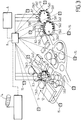
- Fig. 3 shows a plant 9 for wastewater treatment, equipped with devices according to the invention with several injectors 5a1 ... 5b3 installed on the periphery of odor emission zones consisting of basins 10, 11, and a zone 12 treatment tanks, or waste storage areas and maturing organic or other materials.
- the injectors 5a1, ... 5b3 are distributed in at least two sectors Sa1, Sb1 ... Sa3, Sb3 around the source.
- Each sector is independently supplied with pressurized air by a ramp whose flow rate is controlled by a damper or a motorized valve 13a1 ... 13b3 located on either side of an air injection from a fan 8.1 , 8.2, 8.3.
- each sector extends substantially along a semicircle and is respectively fed, via a register or an automated valve 13a1, 13b1, by a fan 8.1 whose discharge is connected to a portion of pipe between the valves 13a1 and 13b1 controlling the flow to the sectors Sa1, Sb1.
- Injectors 5a1, 5b1, represented in reduced numbers to simplify on Fig. 3 are preferably evenly distributed around the periphery of the odor source constituted by the pond 10.
- the distance between two adjacent injectors can be of the order of at least 1 m, and can reach 5 m and more depending on the perimeter to be treated.
- the wind direction detected by an air sleeve 14 and the wind force detected by an anemometer (not shown) are transmitted to a measurement acquisition unit B, and the pressurized air supply is directed towards the sector located on the side of the basin opposite to the direction of the wind.
- the number of injector sectors disposed at the periphery of a source may be greater than two in order to take better account of the direction of the wind and to limit the number of injectors per sector.
- each sector of injectors is powered separately.
- the upwardly directed air jets 7 allow the flow of foul gas to burst and quickly disperse the odor plume during periods of falling wind.
- the adjustment of the air pressure is ensured by a speed controller of the fan motor 8.1, 8.2, 8.3 concerned, or by any other mechanical means, in particular a register.
- the air pressure at the injectors is adjusted by the central B, generally between 50 daPa and 300daPa, depending on the atmospheric conditions, direction and intensity of the wind, pressure and external temperature.
- the injectors can be totally stopped when the weather conditions are favorable to the natural dispersion of the odors, in particular in high wind, or on the contrary by total calm with high atmospheric pressure.
- Odor sensors 15, in particular electrochemical, are distributed at an appropriate distance around the plant 9 to make a continuous measurement of the concentration of the most malodorous molecules, such as H 2 S, NH 3 , mercaptan.
- the results of the measurements thus carried out are transmitted to the central B of acquisition of the various parameters and meteorological measurements.
- the data collected by the central unit B is transmitted to a unit A constituted by a computer equipped with a program for managing and automatically controlling the various functions.
- a digital screen, not shown, indicates the displacement of the odor plume, measurements and dispersing equipment in action.
- the control unit B controls the actuators of the valves 13a1, 13b1 ... 13b3 to regulate their operation, particularly at the flow rate.
- the arrangement of the odor sensors 15 around the plant 9 makes it possible to act in real time and to modulate the operation of the dispersing device malodorous effluents by induction taking into account the meteorological conditions of the site: speed and direction of the wind, temperature and humidity of the air, atmospheric pressure.
- the measurements provided by the sensors 15 make it possible to correct the operating parameters and to check the efficiency of the device.
- control unit B keeps the fans 8.1, 8.2, 8.3 stopped and the valves 13a1, 13b1 ... 13a3 , 13b3 in the closed position.
- control unit B controls the starting of at least one of the fans 8.1, 8.2, 8.3, and opening the appropriate valve 13a1 ... 13b3, so that the appropriate injectors are operated.
- the sensors 15 make it possible to check whether the dispersion efficiency is sufficient for the odor level to drop below the determined threshold.
- the odor level can not be reduced to a value below the tolerable threshold, an operator will warn plant personnel and residents, or stop, as far as possible, sources of gaseous effluents malodorous.
- the device with air injectors according to the invention makes it possible to ensure two effects: a dilution of the plume of malodorous gaseous effluents and a rising effect of this plume.
- Masking products can be injected simultaneously into the air supplying the injectors 5a1 ... 5b3.
- Dispersion modeling software of the various sources of smelly gaseous effluents is advantageously installed in the unit A to allow to anticipate the intensity of formation of malodorous gaseous effluents, and the formation of plumes according to the meteorological conditions. It is then possible to act preventively by operating the sectors of appropriate injectors.
- the device according to the invention concerns not only open-air installations, but also installations of the semi-closed type, that is to say those which comprise a cover with outlet orifices devoid of high chimneys.
- These include greenhouses for sludge drying sewage treatment plants; such greenhouses have a roof in which openings are provided for the evacuation of the effluents.
- air injectors could be distributed around a greenhouse to disperse the effluents that escape through the openings of the roof.
- the invention has many advantages.
- the automatic control of the induction odor dispersion device controlled by the control system comprising the odor sensors 15, makes it possible to control and control the level of odor units at the periphery of the plant 9, and also to continuously optimize the operation of the device both preventively and in corrective action according to the different parameters measured.
- the energy consumption of the device is relatively low compared to the significant dilution effect with the ambient air.
- the device is automatically regulated to obtain the maximum dispersion effect while limiting its power consumption.
- the device is simple to implement and inexpensive with respect to an installation for the capture and biological chemical treatment of malodorous waste gases.
- the device can be installed on new or existing units.
Landscapes
- Engineering & Computer Science (AREA)
- Chemical & Material Sciences (AREA)
- Health & Medical Sciences (AREA)
- Chemical Kinetics & Catalysis (AREA)
- General Health & Medical Sciences (AREA)
- Public Health (AREA)
- Veterinary Medicine (AREA)
- Animal Behavior & Ethology (AREA)
- Life Sciences & Earth Sciences (AREA)
- Epidemiology (AREA)
- Mechanical Engineering (AREA)
- General Engineering & Computer Science (AREA)
- Combustion & Propulsion (AREA)
- Analytical Chemistry (AREA)
- General Chemical & Material Sciences (AREA)
- Oil, Petroleum & Natural Gas (AREA)
- Treating Waste Gases (AREA)
- Disinfection, Sterilisation Or Deodorisation Of Air (AREA)
Description
- L'invention est relative à un dispositif de dispersion à la source des émissions d'effluents gazeux nauséabonds, dégagés de manière diffuse par des sources situées à proximité du sol, en particulier par des bassins de traitement d'eaux usées ou toute autre activité qui dégage des odeurs.
- De nombreuses activités industrielles émettent des odeurs nauséabondes qui se dispersent au gré du vent. Ces effluves peuvent générer une gêne importante pour les riverains. Les émissions d'odeur sont difficilement contrôlables, en particulier lorsqu'il n'est pas possible de les confiner dans une enceinte étanche, et lorsque les surfaces d'émission sont importantes et à géométrie variable.
- Les odeurs ressenties sont relatives à la concentration et à la nature chimique des molécules produites au niveau de la source d'odeurs. De nombreux facteurs météorologiques influent sur les émissions et surtout sur la dispersion des odeurs au niveau de l'environnement. Il s'agit en particulier de :
- la vitesse et du sens du vent,
- l'humidité et la température de l'air ambiant,
- la pression atmosphérique,
- l'effet du relief et des bâtiments avoisinants qui peuvent produire des courants rabattants.
- Divers moyens de réduction de l'impact des nuisances olfactives ont été proposés.
- Afin de favoriser la dispersion des gaz ou de l'air nauséabond, après un traitement chimique ou biologique, les effluents gazeux peuvent être dispersés à une certaine hauteur dans l'atmosphère par des cheminées. La hauteur des cheminées est variable selon la nature et la composition des gaz, la réglementation en vigueur et les résultats de l'étude de dispersion des polluants gazeux, particulaires et malodorants.
- La dispersion des gaz dans l'environnement est améliorée en augmentant la hauteur de cheminée. Un régime de vents turbulents et soutenus a pour effet de mélanger les gaz avec l'air ambiant et de favoriser ainsi la dispersion des polluants.
- L'effet de dispersion des polluants qui est lié à la hauteur d'éjection des gaz dans l'atmosphère est parfois annihilé par des courants d'air (vents) rabattants. Ces conditions défavorables peuvent entraîner une concentration de polluants ou d'odeurs au niveau du sol supérieure au seuil maximal admissible ressenti, ceci malgré le respect de la réglementation concernant les rejets de polluants en sortie des exutoires.
EP 2161446 décrit une éolienne qui favorise la dispersion de gaz dans l'atmosphère à proximité d'une station d'épuration d'eaux résiduaires et qui comprend un mât vertical équipé d'un rotor avec pales, le mât pouvant ainsi servir pour l'évacuation de gaz.WO 2010/044 055 a proposé d'améliorer et de favoriser la dispersion des gaz en prévoyant au moins un injecteur d'air ou de gaz auxiliaire installé à proximité du débouché d'une cheminée et orienté vers le haut de manière à disperser les gaz. - Les émissions peuvent être diffuses et provenir, par exemple, de grands bassins de stations d'épuration, de centres d'enfouissement, de zones de stockage de déchets organiques, d'aires de maturation de matières organiques et autres installations similaires. De telles installations ne sont pas nécessairement à ciel ouvert, et peuvent être recouvertes au moins en partie, mais les effluents gazeux ne sont plus canalisés vers un exutoire, notamment une cheminée. Il n'est alors plus possible ou difficile et coûteux de capter à la source les effluves nauséabonds, et un moyen utilisé pour lutter contre les odeurs consiste à masquer ces odeurs en diffusant des produits "blancs" dont l'objectif est de réduire l'impact olfactif, en couvrant les odeurs.
- Un tel moyen présente une efficacité très limitée car il n'agit que localement dans la zone de diffusion des produits masquants. De plus, les molécules utilisées ne sont pas totalement neutres pour l'environnement.
- Afin d'évaluer d'une manière objective le taux d'odeur ambiant, des capteurs électrochimiques ont été mis au point. De tels capteurs sont positionnés dans les zones de présence humaine pour mesurer en continu la concentration en molécules les plus odorantes telles que H2S, NH3, mercaptan. Ces capteurs permettent de convertir les mesures chimiques en unités d'odeur qui font référence à la perception odorante humaine, et d'indiquer le facteur de nuisance en cours.
- Ces capteurs sont utiles car ils permettent de prévenir les riverains d'un pic d'émission et de prévenir le public avant un constat a posteriori qui entraîne de nombreuses plaintes. Toutefois, ces mesures d'odeur n'ont pas d'effet correctif sur les émissions ni sur leur perception.
- L'invention a pour but, surtout, de fournir un dispositif qui permet d'améliorer significativement la dispersion des effluents gazeux nauséabonds dégagés de manière diffuse par des installations qui ne permettent pas de canaliser ces effluents. Le dispositif selon l'invention est un dispositif de dispersion à la source des émissions d'effluents gazeux nauséabonds, caractérisé en ce qu'il comporte :
- un bassin source d'effluents gazeux nauséabonds,
- au moins deux injecteurs (5a, 5b) d'air ou de gaz auxiliaire orientés vers le haut, installés à la périphérie du bassin source d'effluents gazeux nauséabonds, dans des zones opposées, de manière à disperser les effluents gazeux nauséabonds,
- des moyens d'alimentation des injecteurs, chaque injecteur étant alimenté par un moyen d'alimentation séparé,
- et des moyens de commande sensibles au sens du vent agencés pour sélectionner la mise en fonctionnement du ou des injecteur(s) dont la situation, selon le sens du vent, est la plus favorable pour assurer la dispersion et/ou la remontée du panache d'effluents gazeux.
- De préférence, le dispositif comporte des détecteurs d'odeurs répartis à la périphérie d'une installation comportant au moins une source d'odeurs nauséabondes, ces détecteurs étant agencés pour communiquer les résultats de leurs mesures à une centrale d'acquisition de mesures reliée à une unité de commande qui, selon les résultats des mesures, met en action au moins un ventilateur pour alimenter au moins un secteur approprié d'injecteurs.
- Généralement, les injecteurs sont situés à une hauteur inférieure à celle du bord supérieur de la source d'odeurs, en particulier en bordure de la zone d'émission d'odeurs, c'est-à-dire à proximité du bord supérieur de la source d'odeurs.
- Avantageusement, le dispositif comporte au moins trois secteurs d'injecteurs installés à la périphérie d'une, ou de chaque, source d'odeurs nauséabondes, chaque secteur comportant au moins un injecteur.
- Chaque secteur angulaire et ses injecteurs, sont alimentés par une rampe de distribution d'air équipée d'une vanne à commande motorisée, la rampe étant reliée au refoulement d'un ventilateur.
- De préférence, les injecteurs sont à orientation réglable.
- Les moyens d'alimentation des injecteurs et les moyens de commande peuvent être prévus pour assurer une pression variable en fonction des conditions atmosphériques et de mesures d'unités d'odeur.
- Avantageusement, l'unité de commande est pilotée par un logiciel de gestion et de contrôle programmé pour prendre en considération les paramètres de dispersion et les mesures d'unités d'odeur en temps réel.
- L'unité de commande peut être pilotée par un logiciel de simulation prédictif de la dispersion naturelle du panache d'odeurs, intégré pour une action préventive de commande automatique du dispositif de dispersion par induction.
- Le dispositif peut comporter un moyen d'injection de produits « masquants » dans l'air qui alimente les injecteurs.
- Avantageusement, les moyens d'alimentation des injecteurs comprennent au moins un ventilateur à vitesse réglable, et au moins une conduite de liaison entre la sortie du ventilateur et une rampe d'alimentation du ou des injecteurs.
- De préférence, les moyens d'alimentation du ou des injecteurs sont réglables pour permettre de moduler la pression et le débit d'air ou de gaz auxiliaire envoyé aux injecteurs selon les conditions atmosphériques du moment, et les propriétés du panache de gaz, l'arrêt des moyens d'alimentation étant commandé lorsque la dispersion naturelle est suffisante ou les conditions pour lesquelles les émissions d'odeurs sont faibles.
- L'invention consiste, mises à part les dispositions évoquées ci-dessus, en un certain nombre d'autres dispositions dont il sera plus explicitement question ci-après à propos d'exemples décrits avec référence aux dessins annexés, mais qui ne sont nullement limitatifs. Sur ces dessins :
-
Fig. 1 est un schéma illustrant un bassin de traitement d'eau selon l'état de la technique. -
Fig. 2 est un schéma, semblable à celui deFig. 1 , du bassin avec dispositif selon l'invention pour disperser les émissions d'effluents gazeux, et -
Fig. 3 est un schéma d'une usine de traitement d'eaux usées dont les différentes sources d'effluents gazeux nauséabonds sont équipées de dispositifs selon l'invention. - En se reportant à
Fig. 1 des dessins, on peut voir un bassin 1 de traitement d'eaux usées, selon l'état de la technique. Un tel bassin est généralement circulaire, et son diamètre peut atteindre 30 m et plus. Le bassin 1 dégage des panaches 2 d'effluents gazeux nauséabonds. - Le volume des panaches 2 dépend essentiellement de l'évaporation et donc de paramètres constitués par la vitesse de l'air de balayage en surface du bassin, la température ambiante, l'hygrométrie et la pression atmosphérique. Les panaches 2 sont poussés par le vent dont le sens est schématisé par une flèche 3 et peuvent atteindre des habitations M, qui se trouvent du côté du bassin opposé au sens du vent. Leurs habitants vont ainsi être incommodés par les effluents dégagés. Cette gêne sera d'autant plus forte dans le cas de vents rabattants, illustrés par la flèche 4 sur
Fig. 1 , en direction des habitations. - Afin d'augmenter la dispersion des odeurs nauséabondes dans l'air ambiant, un dispositif D (
Fig.2 ) selon l'invention comporte au moins deux injecteurs 5a, 5b d'air, ou de gaz auxiliaire, orientés vers le haut et constituant des inducteurs pour disperser les effluents gazeux. Les injecteurs 5a, 5b sont alimentés en air à moyenne pression, notamment comprise entre 50 daPa et 300 daPa, par des rampes 6a, 6b branchées sur le refoulement d'un ventilateur non visible surFig.2 . Les rampes ou conduites d'alimentation, telles que 6a, 6b sont avantageusement réalisées en tôle spiralée ou en autre matériau léger (notamment textile). - Les injecteurs 5a, 5b sont placés en périphérie de chaque source d'émission d'odeurs, de manière à assurer une dispersion rapide des odeurs par leur dilution dans l'air ambiant. Les injecteurs 5a, 5b sont situés à proximité du sol, à une hauteur voisine de la zone d'émission. L'induction créée par un jet d'air 7 orienté vers le haut favorise l'ascension dynamique et la dispersion du panache malodorant 2 lorsque les effets d'un vent rabattant sont supérieurs à ceux dus à la différence de densité entre les gaz et l'air ambiant.
- Les rampes 6a, 6b constituent des moyens d'alimentation séparés des injecteurs. Ainsi, chaque injecteur 5a, 5b est alimenté par un moyen d'alimentation séparé.
- La distribution d'air moteur vers les injecteurs 5a, 5b peut ainsi être fractionnée de manière à permettre de sélectionner le ou les injecteurs à mettre en fonctionnement selon le sens du vent et la localisation d'émission des odeurs. Selon le schéma de
Fig. 2 , il suffit de faire fonctionner l'injecteur 5a situé du côté du bassin 1 opposé au sens du vent 3, pour obtenir un effet satisfaisant. - Avantageusement, comme illustré sur
Fig. 3 , des moyens de commande B sensibles au sens du vent et à différents paramètres météorologiques, sont prévus pour assurer l'alimentation du ou des injecteur(s) dont la position est la plus favorable pour assurer la dispersion et la remontée du panache d'effluents gazeux. - Ainsi, les moyens de commande B sensibles au sens du vent sont agencés pour sélectionner la mise en fonctionnement du ou des injecteur(s) 5a, 5b dont la situation, selon le sens du vent, est la plus favorable pour assurer la dispersion et/ou la remontée du panache d'effluents gazeux.
- La pression en sortie des jets d'air est variable et réglable de manière à adapter en permanence le taux d'induction, ou taux d'entraînement du panache par le jet 7 dirigé vers le haut, par rapport aux besoins et afin de limiter la consommation d'énergie, essentiellement électrique, du dispositif d'alimentation en air moteur. Ce dispositif d'alimentation comporte, pour chaque source d'odeurs, au moins un ventilateur 8.1, 8.2, 8.3 (
Fig. 3 ) moyenne pression, notamment de 50 daPa à 300daPa, à vitesse variable, réglable. -
Fig. 3 montre une usine 9 de traitement d'eaux usées, équipée de dispositifs selon l'invention avec plusieurs injecteurs 5a1... 5b3 installés en périphérie de zones d'émission d'odeurs constituées de bassins 10, 11, et d'une zone 12 de cuves de traitement, ou de surfaces de stockage de déchets et de maturation de matières organiques ou autres. Au niveau de chaque source d'effluves malodorants, les injecteurs 5a1, ...5b3 sont répartis en au moins deux secteurs Sa1, Sb1...Sa3, Sb3 autour de la source. Chaque secteur est alimenté indépendamment en air sous pression par une rampe dont le débit est contrôlé par un registre ou une vanne motorisée 13a1 ... 13b3, située de part et d'autre d'une injection d'air provenant d'un ventilateur 8.1, 8 .2, 8.3. - Pour le bassin 10, deux secteurs Sa1, Sb1 d'injecteurs 5a1, 5b1 sont prévus autour du bassin. Chaque secteur s'étend suivant sensiblement un demi-cercle et est alimenté respectivement, par l'intermédiaire d'un registre ou d'une vanne automatisée 13a1, 13b1, par un ventilateur 8.1 dont le refoulement est branché sur une partie de conduite comprise entre les vannes 13a1 et 13b1 contrôlant le débit vers les secteurs Sa1, Sb1.
- Les injecteurs 5a1, 5b1, représentés en nombre réduit pour simplifier sur
Fig. 3 , sont de préférence répartis régulièrement à la périphérie de la source d'odeurs constituée par le bassin 10. La distance entre deux injecteurs voisins peut être de l'ordre d'au moins 1 m, et peut atteindre 5 m et plus selon le périmètre à traiter. Le sens du vent détecté par une manche à air 14 et la force du vent détectée par un anémomètre (non représenté) sont transmis à une centrale d'acquisition de mesures B, et l'alimentation en air sous pression est dirigée vers le secteur situé du côté du bassin opposé au sens du vent. - Des dispositions semblables sont adoptées pour le bassin 11 et pour la source d'émission 12, les éléments identiques étant désignés par les mêmes références affectées de 2 ou 3 comme dernier chiffre.
- Le nombre de secteurs d'injecteurs disposés à la périphérie d'une source peut être supérieur à deux afin de mieux prendre en compte le sens du vent et de limiter le nombre d'injecteurs par secteur. Avantageusement, chaque secteur d'injecteurs est alimenté séparément.
- Les jets d'air 7 orientés vers le haut permettent d'éclater le flux de gaz nauséabonds et de disperser rapidement le panache d'odeurs pendant les périodes de vents rabattants.
- Le réglage de la pression d'air est assuré par un variateur de vitesse du moteur du ventilateur 8.1, 8.2, 8.3 concerné, ou par tout autre moyen mécanique, notamment un registre.
- La pression d'air au niveau des injecteurs est ajustée par la centrale B, généralement entre 50 daPa et 300daPa, selon les conditions atmosphériques, sens et intensité du vent, pression et température externe. Les injecteurs peuvent être totalement arrêtés lorsque les conditions météorologiques sont favorables à la dispersion naturelle des odeurs, notamment par grand vent, ou au contraire par calme total avec pression atmosphérique élevée.
- Des capteurs d'odeurs 15, notamment électrochimiques, sont répartis à une distance appropriée tout autour de l'usine 9 pour effectuer une mesure en continu de la concentration en molécules les plus malodorantes, telles que H2S, NH3, mercaptan. Les résultats des mesures ainsi réalisées sont transmis à la centrale B d'acquisition des différents paramètres et des mesures météorologiques. Les données recueillies par la centrale B sont transmises à une unité A constituée par un ordinateur équipé d'un programme de gestion et de commande automatique des différentes fonctions. Un écran numérique, non représenté, permet d'indiquer le déplacement du panache d'odeurs, les mesures et les équipements de dispersion en action. La centrale B commande les actionneurs des vannes 13a1, 13b1... 13b3 pour régler leur fonctionnement, notamment au niveau du débit.
- La disposition des capteurs d'odeurs 15 autour de l'usine 9 permet d'agir en temps réel et de moduler le fonctionnement du dispositif de dispersion des effluents malodorants par induction en prenant en compte les conditions météorologiques du site : vitesse et sens du vent, température et humidité de l'air, pression atmosphérique. Les mesures fournies par les capteurs 15 permettent de corriger les paramètres de fonctionnement et de vérifier l'efficacité du dispositif.
- Le fonctionnement du dispositif pour lutter contre les émissions d'effluents gazeux malodorants résulte des explications qui précèdent.
- Si les informations fournies par les capteurs d'odeurs 15 ne font pas apparaître un niveau d'odeur dépassant un seuil déterminé, la centrale B maintient les ventilateurs 8.1, 8.2, 8.3 à l'arrêt et les vannes 13a1, 13b1 ... 13a3, 13b3 en position de fermeture.
- Si les capteurs 15 signalent un dépassement du seuil déterminé dans une zone, généralement située du côté de l'usine opposé au sens du vent, la centrale B commande la mise en marche de l'un au moins des ventilateurs 8.1, 8.2, 8.3, et l'ouverture de la vanne appropriée 13a1...13b3, pour que les injecteurs appropriés soient mis en fonctionnement.
- Les capteurs 15 permettent de vérifier si l'efficacité de dispersion est suffisante pour que le niveau d'odeur baisse au-dessous du seuil déterminé.
- Pour le cas où le niveau d'odeur ne pourrait être ramené à une valeur inférieure au seuil tolérable, un opérateur préviendra le personnel de l'usine et les riverains, ou fera arrêter, dans la mesure du possible, les sources d'effluents gazeux malodorants.
- Le dispositif avec injecteurs d'air selon l'invention permet d'assurer deux effets : une dilution du panache d'effluents gazeux malodorants et un effet de montée de ce panache.
- Des produits masquants peuvent être injectés simultanément dans l'air qui alimente les injecteurs 5a1... 5b3.
- Un logiciel de modélisation de dispersion des diverses sources d'effluents gazeux malodorants est avantageusement installé dans l'unité A pour permettre d'anticiper l'intensité de formation d'effluents gazeux malodorants, et la formation de panaches selon les conditions météorologiques. Il est alors possible d'agir préventivement en faisant fonctionner les secteurs d'injecteurs appropriés.
- Le dispositif selon l'invention concerne non seulement des installations à ciel ouvert, mais aussi les installations de type semi-fermées, c'est-à-dire celles qui comportent une couverture avec des orifices de sortie dépourvus de hautes cheminées. Il s'agit notamment de serres pour le séchage de boues de stations d'épuration ; de telles serres comportent une toiture dans laquelle sont prévues des ouvertures, pour l'évacuation des effluents. Selon l'invention, des injecteurs d'air pourraient être répartis autour d'une serre pour disperser les effluents qui s'échappent par les ouvertures du toit.
- L'invention présente de nombreux avantages.
- L'asservissement automatique du dispositif de dispersion d'odeurs par induction, commandé par le système de contrôle comportant les capteurs d'odeurs 15, permet de contrôler et de maîtriser le niveau d'unités d'odeur en périphérie de l'usine 9, et également d'optimiser en permanence le fonctionnement du dispositif à la fois préventivement et en action corrective selon les différents paramètres mesurés.
- La consommation d'énergie du dispositif est relativement faible par rapport à l'effet de dilution important avec l'air ambiant. Le dispositif est régulé automatiquement afin d'obtenir l'effet de dispersion maximal tout en limitant sa consommation d'énergie électrique.
- Le dispositif est simple à mettre en oeuvre et peu coûteux au regard d'une installation de captation et de traitement chimique biologique des effluents gazeux malodorants. Le dispositif peut être installé sur des unités neuves ou existantes.
- L'invention s'applique à toute installation à protéger contre les nuisances olfactives diffuses, notamment
- bassins d'épaississement ou d'aération de STEP (stations d'épuration d'eaux usées),
- centres de stockage des déchets,
- plates-formes de compostage de matières organiques,
- centres de transfert de déchets,
- toute zone d'activité industrielle ouverte émettant des odeurs nauséabondes.
Claims (12)
- Dispositif de dispersion à la source des émissions d'effluents gazeux nauséabonds, caractérisé en ce qu'il comporte :- un bassin (1) source d'effluents gazeux nauséabonds,- au moins deux injecteurs (5a, 5b) d'air ou de gaz auxiliaire orientés vers le haut, installés à la périphérie du bassin (1) source d'effluents gazeux nauséabonds, dans des zones opposées, de manière à disperser les effluents gazeux nauséabonds,- des moyens d'alimentation (6a, 6b) des injecteurs, chaque injecteur étant alimenté par un moyen d'alimentation séparé,- et des moyens de commande sensibles au sens du vent agencés pour sélectionner la mise en fonctionnement du ou des injecteur(s) dont la situation, selon le sens du vent, est la plus favorable pour assurer la dispersion et/ou la remontée du panache d'effluents gazeux.
- Dispositif selon la revendication 1, caractérisé en ce qu'il comporte des détecteurs d'odeurs (15) répartis à la périphérie d'une installation comportant au moins une source (10,11,12) d'odeurs nauséabondes, ces détecteurs étant agencés pour communiquer les résultats de leurs mesures à une centrale (B) d'acquisition de mesures reliée à une unité de commande (A) qui, selon les résultats des mesures, met en action au moins un ventilateur (8.1,8.2,8.3) pour alimenter au moins un secteur approprié (Sa1...Sb3) d'injecteurs.
- Dispositif selon la revendication 1 ou 2, caractérisé en ce que les injecteurs (5a, 5b) sont situés à proximité du bord supérieur de la source d'odeurs,
- Dispositif selon l'une quelconque des revendications précédentes, caractérisé en ce qu'il comporte au moins trois secteurs d'injecteurs installés à la périphérie d'une, ou de chaque, source d'odeurs nauséabondes, chaque secteur comportant au moins un injecteur.
- Dispositif selon l'une quelconque des revendications précédentes, caractérisé en ce que chaque secteur angulaire (Sa1,...Sb3), et ses injecteurs, sont alimentés par une rampe de distribution d'air équipée d'une vanne à commande motorisée (13a1,...13b3), la rampe étant reliée au refoulement d'un ventilateur (8a1, 8a2, 8a3).
- Dispositif selon l'une quelconque des revendications précédentes, caractérisé en ce que les injecteurs (5a, 5b) sont à orientation réglable.
- Dispositif selon l'une quelconque des revendications précédentes, caractérisé en ce que les moyens d'alimentation (6a, 6b) des injecteurs et les moyens de commande sont prévus pour assurer une pression variable en fonction des conditions atmosphériques et de mesures d'unités d'odeur.
- Dispositif selon la revendication 2, caractérisé en ce que l'unité de commande (A) est pilotée par un logiciel de gestion et de contrôle programmé pour prendre en considération les paramètres de dispersion et les mesures d'unités d'odeur en temps réel.
- Dispositif selon la revendication 2 ou 8, caractérisé en ce que l'unité de commande (A) est pilotée par un logiciel de simulation prédictif de la dispersion naturelle du panache d'odeurs (2), intégré pour une action préventive de commande automatique du dispositif de dispersion par induction.
- Dispositif selon l'une quelconque des revendications précédentes, caractérisé en ce qu'il comporte un moyen d'injection de produits « masquants » dans l'air qui alimente les injecteurs.
- Dispositif selon l'une quelconque des revendications précédentes, caractérisé en ce que les moyens d'alimentation des injecteurs comprennent au moins un ventilateur (8.1, 8.2, 8.3) à vitesse réglable, et au moins une conduite de liaison entre la sortie du ventilateur et une rampe d'alimentation du ou des injecteurs.
- Dispositif selon la revendication 11, caractérisé en ce que les moyens d'alimentation du ou des injecteurs sont réglables pour permettre de moduler la pression et le débit d'air ou de gaz auxiliaire envoyé aux injecteurs selon les conditions atmosphériques du moment, et les propriétés du panache de gaz, l'arrêt des moyens d'alimentation étant commandé lorsque la dispersion naturelle est suffisante.
Priority Applications (1)
| Application Number | Priority Date | Filing Date | Title |
|---|---|---|---|
| PL15709747T PL3105186T3 (pl) | 2014-02-14 | 2015-02-12 | Urządzenie do rozpraszania u źródła emisji wyziewów gazowych powodujących mdłości |
Applications Claiming Priority (2)
| Application Number | Priority Date | Filing Date | Title |
|---|---|---|---|
| FR1451164A FR3017545A1 (fr) | 2014-02-14 | 2014-02-14 | Dispositif pour disperser a la source les emissions d'effluents gazeux nauseabonds |
| PCT/IB2015/051052 WO2015121820A1 (fr) | 2014-02-14 | 2015-02-12 | Dispositif pour disperser a la source les emissions d'effluents gazeux nauseabonds |
Publications (2)
| Publication Number | Publication Date |
|---|---|
| EP3105186A1 EP3105186A1 (fr) | 2016-12-21 |
| EP3105186B1 true EP3105186B1 (fr) | 2018-04-04 |
Family
ID=50729650
Family Applications (1)
| Application Number | Title | Priority Date | Filing Date |
|---|---|---|---|
| EP15709747.8A Active EP3105186B1 (fr) | 2014-02-14 | 2015-02-12 | Dispositif pour disperser a la source les emissions d'effluents gazeux nauseabonds |
Country Status (8)
| Country | Link |
|---|---|
| US (1) | US10092671B2 (fr) |
| EP (1) | EP3105186B1 (fr) |
| CN (1) | CN106132509B (fr) |
| AU (1) | AU2015216615B2 (fr) |
| ES (1) | ES2675021T3 (fr) |
| FR (1) | FR3017545A1 (fr) |
| PL (1) | PL3105186T3 (fr) |
| WO (1) | WO2015121820A1 (fr) |
Families Citing this family (12)
| Publication number | Priority date | Publication date | Assignee | Title |
|---|---|---|---|---|
| US11636870B2 (en) | 2020-08-20 | 2023-04-25 | Denso International America, Inc. | Smoking cessation systems and methods |
| US11813926B2 (en) | 2020-08-20 | 2023-11-14 | Denso International America, Inc. | Binding agent and olfaction sensor |
| US11881093B2 (en) | 2020-08-20 | 2024-01-23 | Denso International America, Inc. | Systems and methods for identifying smoking in vehicles |
| US12251991B2 (en) | 2020-08-20 | 2025-03-18 | Denso International America, Inc. | Humidity control for olfaction sensors |
| US11760169B2 (en) | 2020-08-20 | 2023-09-19 | Denso International America, Inc. | Particulate control systems and methods for olfaction sensors |
| US11828210B2 (en) | 2020-08-20 | 2023-11-28 | Denso International America, Inc. | Diagnostic systems and methods of vehicles using olfaction |
| US11932080B2 (en) | 2020-08-20 | 2024-03-19 | Denso International America, Inc. | Diagnostic and recirculation control systems and methods |
| US12017506B2 (en) | 2020-08-20 | 2024-06-25 | Denso International America, Inc. | Passenger cabin air control systems and methods |
| US12269315B2 (en) | 2020-08-20 | 2025-04-08 | Denso International America, Inc. | Systems and methods for measuring and managing odor brought into rental vehicles |
| US11760170B2 (en) | 2020-08-20 | 2023-09-19 | Denso International America, Inc. | Olfaction sensor preservation systems and methods |
| US12377711B2 (en) | 2020-08-20 | 2025-08-05 | Denso International America, Inc. | Vehicle feature control systems and methods based on smoking |
| CN119655152B (zh) * | 2024-12-25 | 2025-07-22 | 天津商业大学 | 应用于农业自动化浇灌设备的监测运维系统 |
Family Cites Families (5)
| Publication number | Priority date | Publication date | Assignee | Title |
|---|---|---|---|---|
| US2544769A (en) * | 1945-12-29 | 1951-03-13 | Scovill Manufacturing Co | Fume and vapor control for cleansing tanks |
| FR2740862B1 (fr) | 1995-11-03 | 1998-01-23 | Amphoux Andre | Dispositif pour aspirer un fluide gazeux a travers un conduit pour le rejeter a l'exterieur de celui-ci |
| US5930994A (en) * | 1996-07-02 | 1999-08-03 | Ibiden Co., Ltd. | Reverse cleaning regeneration type exhaust emission control device and method of regenerating the same |
| FR2935762B1 (fr) * | 2008-09-09 | 2013-02-15 | Suez Environnement | Eolienne |
| FR2937120B1 (fr) * | 2008-10-14 | 2010-11-19 | Suez Environnement | Dispositif de dispersion de gaz sortant d'une cheminee |
-
2014
- 2014-02-14 FR FR1451164A patent/FR3017545A1/fr not_active Withdrawn
-
2015
- 2015-02-12 AU AU2015216615A patent/AU2015216615B2/en active Active
- 2015-02-12 CN CN201580015498.1A patent/CN106132509B/zh active Active
- 2015-02-12 US US15/118,007 patent/US10092671B2/en active Active
- 2015-02-12 ES ES15709747.8T patent/ES2675021T3/es active Active
- 2015-02-12 EP EP15709747.8A patent/EP3105186B1/fr active Active
- 2015-02-12 WO PCT/IB2015/051052 patent/WO2015121820A1/fr not_active Ceased
- 2015-02-12 PL PL15709747T patent/PL3105186T3/pl unknown
Also Published As
| Publication number | Publication date |
|---|---|
| PL3105186T3 (pl) | 2019-03-29 |
| CN106132509B (zh) | 2019-04-23 |
| FR3017545A1 (fr) | 2015-08-21 |
| EP3105186A1 (fr) | 2016-12-21 |
| ES2675021T3 (es) | 2018-07-05 |
| WO2015121820A1 (fr) | 2015-08-20 |
| AU2015216615A1 (en) | 2016-09-01 |
| AU2015216615B2 (en) | 2019-04-11 |
| CN106132509A (zh) | 2016-11-16 |
| US20170007735A1 (en) | 2017-01-12 |
| US10092671B2 (en) | 2018-10-09 |
Similar Documents
| Publication | Publication Date | Title |
|---|---|---|
| EP3105186B1 (fr) | Dispositif pour disperser a la source les emissions d'effluents gazeux nauseabonds | |
| EP3574980B1 (fr) | Bâtiment dépolluant | |
| FR3076601A1 (fr) | Systeme de traitement de l'air pour un batiment ou navire | |
| KR20150070643A (ko) | 복합 시설물 | |
| FR3087136A1 (fr) | Procede et dispositif de gestion d'un dispositif de traitement de gaz vicie. | |
| WO2013029172A1 (fr) | Système et méthode pour contrôler et traiter des émanations gazeuses à l'intérieur d'un puits d'accès d'eaux usées | |
| JP2020182638A (ja) | 環境改善装置 | |
| KR100709605B1 (ko) | 축사 환기 공조 시스템 | |
| CN212260194U (zh) | 有机废弃物养殖装置及系统 | |
| JP6445663B1 (ja) | 生物脱臭装置 | |
| JP6445665B1 (ja) | 生物脱臭方法 | |
| ES2211590T3 (es) | Tratamiento de gas oxidable generado por desechos en una zona de vertedero. | |
| NL2025921B1 (en) | Plant-based air filtration device and its use | |
| KR101185382B1 (ko) | 블록형 관찰로 | |
| LT6501B (lt) | Nuotekų perpumpavimo stočių bei nuotekų valymo stočių dezinfekavimo sistema | |
| JP6445664B1 (ja) | 生物脱臭装置 | |
| FR2758099A1 (fr) | Dispositif pour le drainage des atmospheres urbaines polluees | |
| WO2010044055A1 (fr) | Dispositif de dispersion de gaz sortant d'une cheminée | |
| WO2024200572A1 (fr) | Système de filtration pour un bassin, bassin et procédé de filtration associés | |
| MX2007010499A (es) | Metodo para colocar y operar un arreglo de ventilador dispersor de olor. | |
| Ogunjobi et al. | ENVIRONMENTAL IMPACT ASSESSMENT: A CASE STUDY OF WASTE MANAGEMENT PRACTICE IN LOKOJA | |
| CN121466754A (zh) | 一种基于气体分离膜的粪污暂存区臭气分离与智能控制方法 | |
| EP3365286A1 (fr) | Réacteur biologique séquentiel et procédé mettant en oeuvre le réacteur | |
| JPH03154698A (ja) | 限定水域での溶存酸素量改良方法およびその装置ならびにこれを用いた魚巣構造体 | |
| Rousseille et al. | Use of dispersion modelling for the design and operation of wastewater and composting plants |
Legal Events
| Date | Code | Title | Description |
|---|---|---|---|
| PUAI | Public reference made under article 153(3) epc to a published international application that has entered the european phase |
Free format text: ORIGINAL CODE: 0009012 |
|
| STAA | Information on the status of an ep patent application or granted ep patent |
Free format text: STATUS: REQUEST FOR EXAMINATION WAS MADE |
|
| 17P | Request for examination filed |
Effective date: 20160809 |
|
| AK | Designated contracting states |
Kind code of ref document: A1 Designated state(s): AL AT BE BG CH CY CZ DE DK EE ES FI FR GB GR HR HU IE IS IT LI LT LU LV MC MK MT NL NO PL PT RO RS SE SI SK SM TR |
|
| AX | Request for extension of the european patent |
Extension state: BA ME |
|
| RIN1 | Information on inventor provided before grant (corrected) |
Inventor name: KELLY, ROBERT Inventor name: DUONG, FREDERIC Inventor name: CHANTRE, PATRICK |
|
| DAX | Request for extension of the european patent (deleted) | ||
| REG | Reference to a national code |
Ref country code: DE Ref legal event code: R079 Ref document number: 602015009572 Country of ref document: DE Free format text: PREVIOUS MAIN CLASS: C02F0001000000 Ipc: B05B0015040000 |
|
| GRAP | Despatch of communication of intention to grant a patent |
Free format text: ORIGINAL CODE: EPIDOSNIGR1 |
|
| RIC1 | Information provided on ipc code assigned before grant |
Ipc: F23L 17/16 20060101ALI20170913BHEP Ipc: A61L 9/00 20060101ALN20170913BHEP Ipc: B05B 15/04 20060101AFI20170913BHEP |
|
| STAA | Information on the status of an ep patent application or granted ep patent |
Free format text: STATUS: GRANT OF PATENT IS INTENDED |
|
| RIC1 | Information provided on ipc code assigned before grant |
Ipc: F23L 17/16 20060101ALI20170915BHEP Ipc: A61L 9/00 20060101ALN20170915BHEP Ipc: B05B 15/04 20060101AFI20170915BHEP |
|
| INTG | Intention to grant announced |
Effective date: 20171019 |
|
| GRAS | Grant fee paid |
Free format text: ORIGINAL CODE: EPIDOSNIGR3 |
|
| GRAA | (expected) grant |
Free format text: ORIGINAL CODE: 0009210 |
|
| STAA | Information on the status of an ep patent application or granted ep patent |
Free format text: STATUS: THE PATENT HAS BEEN GRANTED |
|
| AK | Designated contracting states |
Kind code of ref document: B1 Designated state(s): AL AT BE BG CH CY CZ DE DK EE ES FI FR GB GR HR HU IE IS IT LI LT LU LV MC MK MT NL NO PL PT RO RS SE SI SK SM TR |
|
| REG | Reference to a national code |
Ref country code: GB Ref legal event code: FG4D Free format text: NOT ENGLISH |
|
| REG | Reference to a national code |
Ref country code: CH Ref legal event code: EP |
|
| REG | Reference to a national code |
Ref country code: AT Ref legal event code: REF Ref document number: 985030 Country of ref document: AT Kind code of ref document: T Effective date: 20180415 |
|
| REG | Reference to a national code |
Ref country code: IE Ref legal event code: FG4D Free format text: LANGUAGE OF EP DOCUMENT: FRENCH |
|
| REG | Reference to a national code |
Ref country code: DE Ref legal event code: R096 Ref document number: 602015009572 Country of ref document: DE |
|
| REG | Reference to a national code |
Ref country code: ES Ref legal event code: FG2A Ref document number: 2675021 Country of ref document: ES Kind code of ref document: T3 Effective date: 20180705 |
|
| REG | Reference to a national code |
Ref country code: NL Ref legal event code: FP |
|
| REG | Reference to a national code |
Ref country code: LT Ref legal event code: MG4D |
|
| PG25 | Lapsed in a contracting state [announced via postgrant information from national office to epo] |
Ref country code: AL Free format text: LAPSE BECAUSE OF FAILURE TO SUBMIT A TRANSLATION OF THE DESCRIPTION OR TO PAY THE FEE WITHIN THE PRESCRIBED TIME-LIMIT Effective date: 20180404 Ref country code: BG Free format text: LAPSE BECAUSE OF FAILURE TO SUBMIT A TRANSLATION OF THE DESCRIPTION OR TO PAY THE FEE WITHIN THE PRESCRIBED TIME-LIMIT Effective date: 20180704 Ref country code: LT Free format text: LAPSE BECAUSE OF FAILURE TO SUBMIT A TRANSLATION OF THE DESCRIPTION OR TO PAY THE FEE WITHIN THE PRESCRIBED TIME-LIMIT Effective date: 20180404 Ref country code: FI Free format text: LAPSE BECAUSE OF FAILURE TO SUBMIT A TRANSLATION OF THE DESCRIPTION OR TO PAY THE FEE WITHIN THE PRESCRIBED TIME-LIMIT Effective date: 20180404 Ref country code: NO Free format text: LAPSE BECAUSE OF FAILURE TO SUBMIT A TRANSLATION OF THE DESCRIPTION OR TO PAY THE FEE WITHIN THE PRESCRIBED TIME-LIMIT Effective date: 20180704 Ref country code: SE Free format text: LAPSE BECAUSE OF FAILURE TO SUBMIT A TRANSLATION OF THE DESCRIPTION OR TO PAY THE FEE WITHIN THE PRESCRIBED TIME-LIMIT Effective date: 20180404 |
|
| PG25 | Lapsed in a contracting state [announced via postgrant information from national office to epo] |
Ref country code: RS Free format text: LAPSE BECAUSE OF FAILURE TO SUBMIT A TRANSLATION OF THE DESCRIPTION OR TO PAY THE FEE WITHIN THE PRESCRIBED TIME-LIMIT Effective date: 20180404 Ref country code: LV Free format text: LAPSE BECAUSE OF FAILURE TO SUBMIT A TRANSLATION OF THE DESCRIPTION OR TO PAY THE FEE WITHIN THE PRESCRIBED TIME-LIMIT Effective date: 20180404 Ref country code: HR Free format text: LAPSE BECAUSE OF FAILURE TO SUBMIT A TRANSLATION OF THE DESCRIPTION OR TO PAY THE FEE WITHIN THE PRESCRIBED TIME-LIMIT Effective date: 20180404 Ref country code: GR Free format text: LAPSE BECAUSE OF FAILURE TO SUBMIT A TRANSLATION OF THE DESCRIPTION OR TO PAY THE FEE WITHIN THE PRESCRIBED TIME-LIMIT Effective date: 20180705 |
|
| REG | Reference to a national code |
Ref country code: AT Ref legal event code: MK05 Ref document number: 985030 Country of ref document: AT Kind code of ref document: T Effective date: 20180404 |
|
| PG25 | Lapsed in a contracting state [announced via postgrant information from national office to epo] |
Ref country code: PT Free format text: LAPSE BECAUSE OF FAILURE TO SUBMIT A TRANSLATION OF THE DESCRIPTION OR TO PAY THE FEE WITHIN THE PRESCRIBED TIME-LIMIT Effective date: 20180806 |
|
| REG | Reference to a national code |
Ref country code: DE Ref legal event code: R097 Ref document number: 602015009572 Country of ref document: DE |
|
| PG25 | Lapsed in a contracting state [announced via postgrant information from national office to epo] |
Ref country code: SK Free format text: LAPSE BECAUSE OF FAILURE TO SUBMIT A TRANSLATION OF THE DESCRIPTION OR TO PAY THE FEE WITHIN THE PRESCRIBED TIME-LIMIT Effective date: 20180404 Ref country code: RO Free format text: LAPSE BECAUSE OF FAILURE TO SUBMIT A TRANSLATION OF THE DESCRIPTION OR TO PAY THE FEE WITHIN THE PRESCRIBED TIME-LIMIT Effective date: 20180404 Ref country code: CZ Free format text: LAPSE BECAUSE OF FAILURE TO SUBMIT A TRANSLATION OF THE DESCRIPTION OR TO PAY THE FEE WITHIN THE PRESCRIBED TIME-LIMIT Effective date: 20180404 Ref country code: AT Free format text: LAPSE BECAUSE OF FAILURE TO SUBMIT A TRANSLATION OF THE DESCRIPTION OR TO PAY THE FEE WITHIN THE PRESCRIBED TIME-LIMIT Effective date: 20180404 Ref country code: EE Free format text: LAPSE BECAUSE OF FAILURE TO SUBMIT A TRANSLATION OF THE DESCRIPTION OR TO PAY THE FEE WITHIN THE PRESCRIBED TIME-LIMIT Effective date: 20180404 Ref country code: DK Free format text: LAPSE BECAUSE OF FAILURE TO SUBMIT A TRANSLATION OF THE DESCRIPTION OR TO PAY THE FEE WITHIN THE PRESCRIBED TIME-LIMIT Effective date: 20180404 |
|
| REG | Reference to a national code |
Ref country code: CH Ref legal event code: PK Free format text: RECTIFICATIONS |
|
| PLBE | No opposition filed within time limit |
Free format text: ORIGINAL CODE: 0009261 |
|
| STAA | Information on the status of an ep patent application or granted ep patent |
Free format text: STATUS: NO OPPOSITION FILED WITHIN TIME LIMIT |
|
| RIC2 | Information provided on ipc code assigned after grant |
Ipc: A61L 9/00 20060101ALN20170915BHEP Ipc: B05B 15/04 20060101AFI20170915BHEP Ipc: F23L 17/16 20060101ALI20170915BHEP |
|
| PG25 | Lapsed in a contracting state [announced via postgrant information from national office to epo] |
Ref country code: SM Free format text: LAPSE BECAUSE OF FAILURE TO SUBMIT A TRANSLATION OF THE DESCRIPTION OR TO PAY THE FEE WITHIN THE PRESCRIBED TIME-LIMIT Effective date: 20180404 Ref country code: IT Free format text: LAPSE BECAUSE OF FAILURE TO SUBMIT A TRANSLATION OF THE DESCRIPTION OR TO PAY THE FEE WITHIN THE PRESCRIBED TIME-LIMIT Effective date: 20180404 |
|
| 26N | No opposition filed |
Effective date: 20190107 |
|
| PG25 | Lapsed in a contracting state [announced via postgrant information from national office to epo] |
Ref country code: SI Free format text: LAPSE BECAUSE OF FAILURE TO SUBMIT A TRANSLATION OF THE DESCRIPTION OR TO PAY THE FEE WITHIN THE PRESCRIBED TIME-LIMIT Effective date: 20180404 |
|
| REG | Reference to a national code |
Ref country code: CH Ref legal event code: PL |
|
| PG25 | Lapsed in a contracting state [announced via postgrant information from national office to epo] |
Ref country code: LU Free format text: LAPSE BECAUSE OF NON-PAYMENT OF DUE FEES Effective date: 20190212 Ref country code: MC Free format text: LAPSE BECAUSE OF FAILURE TO SUBMIT A TRANSLATION OF THE DESCRIPTION OR TO PAY THE FEE WITHIN THE PRESCRIBED TIME-LIMIT Effective date: 20180404 |
|
| REG | Reference to a national code |
Ref country code: IE Ref legal event code: MM4A |
|
| PG25 | Lapsed in a contracting state [announced via postgrant information from national office to epo] |
Ref country code: LI Free format text: LAPSE BECAUSE OF NON-PAYMENT OF DUE FEES Effective date: 20190228 Ref country code: CH Free format text: LAPSE BECAUSE OF NON-PAYMENT OF DUE FEES Effective date: 20190228 |
|
| PG25 | Lapsed in a contracting state [announced via postgrant information from national office to epo] |
Ref country code: IE Free format text: LAPSE BECAUSE OF NON-PAYMENT OF DUE FEES Effective date: 20190212 |
|
| PG25 | Lapsed in a contracting state [announced via postgrant information from national office to epo] |
Ref country code: TR Free format text: LAPSE BECAUSE OF FAILURE TO SUBMIT A TRANSLATION OF THE DESCRIPTION OR TO PAY THE FEE WITHIN THE PRESCRIBED TIME-LIMIT Effective date: 20180404 |
|
| PG25 | Lapsed in a contracting state [announced via postgrant information from national office to epo] |
Ref country code: MT Free format text: LAPSE BECAUSE OF FAILURE TO SUBMIT A TRANSLATION OF THE DESCRIPTION OR TO PAY THE FEE WITHIN THE PRESCRIBED TIME-LIMIT Effective date: 20180404 |
|
| PG25 | Lapsed in a contracting state [announced via postgrant information from national office to epo] |
Ref country code: CY Free format text: LAPSE BECAUSE OF FAILURE TO SUBMIT A TRANSLATION OF THE DESCRIPTION OR TO PAY THE FEE WITHIN THE PRESCRIBED TIME-LIMIT Effective date: 20180404 |
|
| PG25 | Lapsed in a contracting state [announced via postgrant information from national office to epo] |
Ref country code: IS Free format text: LAPSE BECAUSE OF FAILURE TO SUBMIT A TRANSLATION OF THE DESCRIPTION OR TO PAY THE FEE WITHIN THE PRESCRIBED TIME-LIMIT Effective date: 20180804 |
|
| PG25 | Lapsed in a contracting state [announced via postgrant information from national office to epo] |
Ref country code: HU Free format text: LAPSE BECAUSE OF FAILURE TO SUBMIT A TRANSLATION OF THE DESCRIPTION OR TO PAY THE FEE WITHIN THE PRESCRIBED TIME-LIMIT; INVALID AB INITIO Effective date: 20150212 |
|
| PG25 | Lapsed in a contracting state [announced via postgrant information from national office to epo] |
Ref country code: MK Free format text: LAPSE BECAUSE OF FAILURE TO SUBMIT A TRANSLATION OF THE DESCRIPTION OR TO PAY THE FEE WITHIN THE PRESCRIBED TIME-LIMIT Effective date: 20180404 |
|
| P01 | Opt-out of the competence of the unified patent court (upc) registered |
Effective date: 20230601 |
|
| REG | Reference to a national code |
Ref country code: NL Ref legal event code: PD Owner name: SUEZ INTERNATIONAL; FR Free format text: DETAILS ASSIGNMENT: CHANGE OF OWNER(S), ASSIGNMENT; FORMER OWNER NAME: SUEZ GROUPE Effective date: 20230718 |
|
| REG | Reference to a national code |
Ref country code: BE Ref legal event code: PD Owner name: SUEZ INTERNATIONAL; FR Free format text: DETAILS ASSIGNMENT: CHANGE OF OWNER(S), ASSIGNMENT; FORMER OWNER NAME: SUEZ GROUPE Effective date: 20230615 |
|
| REG | Reference to a national code |
Ref country code: DE Ref legal event code: R081 Ref document number: 602015009572 Country of ref document: DE Owner name: SUEZ INTERNATIONAL, FR Free format text: FORMER OWNER: SUEZ GROUPE, PARIS, FR |
|
| REG | Reference to a national code |
Ref country code: ES Ref legal event code: PC2A Owner name: SUEZ INTERNATIONAL Effective date: 20240319 |
|
| REG | Reference to a national code |
Ref country code: DE Ref legal event code: R082 Ref document number: 602015009572 Country of ref document: DE Representative=s name: LAVOIX MUNICH ZWEIGNIEDERLASSUNG DER CABINET L, DE |
|
| PGFP | Annual fee paid to national office [announced via postgrant information from national office to epo] |
Ref country code: DE Payment date: 20250227 Year of fee payment: 11 |
|
| PGFP | Annual fee paid to national office [announced via postgrant information from national office to epo] |
Ref country code: BE Payment date: 20250227 Year of fee payment: 11 |
|
| REG | Reference to a national code |
Ref country code: GB Ref legal event code: 732E Free format text: REGISTERED BETWEEN 20250529 AND 20250604 |
|
| PGFP | Annual fee paid to national office [announced via postgrant information from national office to epo] |
Ref country code: NL Payment date: 20260226 Year of fee payment: 12 |
|
| PGFP | Annual fee paid to national office [announced via postgrant information from national office to epo] |
Ref country code: GB Payment date: 20260227 Year of fee payment: 12 |
|
| PGFP | Annual fee paid to national office [announced via postgrant information from national office to epo] |
Ref country code: ES Payment date: 20260302 Year of fee payment: 12 |
|
| PGFP | Annual fee paid to national office [announced via postgrant information from national office to epo] |
Ref country code: FR Payment date: 20260225 Year of fee payment: 12 |
|
| PGFP | Annual fee paid to national office [announced via postgrant information from national office to epo] |
Ref country code: PL Payment date: 20260203 Year of fee payment: 12 |