EP3105396B1 - Lageranordnung für eine tür - Google Patents
Lageranordnung für eine tür Download PDFInfo
- Publication number
- EP3105396B1 EP3105396B1 EP15704295.3A EP15704295A EP3105396B1 EP 3105396 B1 EP3105396 B1 EP 3105396B1 EP 15704295 A EP15704295 A EP 15704295A EP 3105396 B1 EP3105396 B1 EP 3105396B1
- Authority
- EP
- European Patent Office
- Prior art keywords
- damper
- bearing arrangement
- door
- bearing
- arrangement according
- Prior art date
- Legal status (The legal status is an assumption and is not a legal conclusion. Google has not performed a legal analysis and makes no representation as to the accuracy of the status listed.)
- Active
Links
Images



Classifications
-
- E—FIXED CONSTRUCTIONS
- E05—LOCKS; KEYS; WINDOW OR DOOR FITTINGS; SAFES
- E05F—DEVICES FOR MOVING WINGS INTO OPEN OR CLOSED POSITION; CHECKS FOR WINGS; WING FITTINGS NOT OTHERWISE PROVIDED FOR, CONCERNED WITH THE FUNCTIONING OF THE WING
- E05F1/00—Closers or openers for wings, not otherwise provided for in this subclass
- E05F1/08—Closers or openers for wings, not otherwise provided for in this subclass spring-actuated, e.g. for horizontally sliding wings
- E05F1/10—Closers or openers for wings, not otherwise provided for in this subclass spring-actuated, e.g. for horizontally sliding wings for swinging wings, e.g. counterbalance
- E05F1/12—Mechanisms in the shape of hinges or pivots, operated by springs
-
- E—FIXED CONSTRUCTIONS
- E05—LOCKS; KEYS; WINDOW OR DOOR FITTINGS; SAFES
- E05F—DEVICES FOR MOVING WINGS INTO OPEN OR CLOSED POSITION; CHECKS FOR WINGS; WING FITTINGS NOT OTHERWISE PROVIDED FOR, CONCERNED WITH THE FUNCTIONING OF THE WING
- E05F1/00—Closers or openers for wings, not otherwise provided for in this subclass
- E05F1/08—Closers or openers for wings, not otherwise provided for in this subclass spring-actuated, e.g. for horizontally sliding wings
- E05F1/10—Closers or openers for wings, not otherwise provided for in this subclass spring-actuated, e.g. for horizontally sliding wings for swinging wings, e.g. counterbalance
- E05F1/12—Mechanisms in the shape of hinges or pivots, operated by springs
- E05F1/1246—Mechanisms in the shape of hinges or pivots, operated by springs with a coil spring perpendicular to the pivot axis
- E05F1/1253—Mechanisms in the shape of hinges or pivots, operated by springs with a coil spring perpendicular to the pivot axis with a compression spring
-
- E—FIXED CONSTRUCTIONS
- E05—LOCKS; KEYS; WINDOW OR DOOR FITTINGS; SAFES
- E05F—DEVICES FOR MOVING WINGS INTO OPEN OR CLOSED POSITION; CHECKS FOR WINGS; WING FITTINGS NOT OTHERWISE PROVIDED FOR, CONCERNED WITH THE FUNCTIONING OF THE WING
- E05F3/00—Closers or openers with braking devices, e.g. checks; Construction of pneumatic or liquid braking devices
- E05F3/04—Closers or openers with braking devices, e.g. checks; Construction of pneumatic or liquid braking devices with liquid piston brakes
- E05F3/10—Closers or openers with braking devices, e.g. checks; Construction of pneumatic or liquid braking devices with liquid piston brakes with a spring, other than a torsion spring, and a piston, the axes of which are the same or lie in the same direction
- E05F3/104—Closers or openers with braking devices, e.g. checks; Construction of pneumatic or liquid braking devices with liquid piston brakes with a spring, other than a torsion spring, and a piston, the axes of which are the same or lie in the same direction with cam-and-slide transmission between driving shaft and piston within the closer housing
-
- E—FIXED CONSTRUCTIONS
- E05—LOCKS; KEYS; WINDOW OR DOOR FITTINGS; SAFES
- E05F—DEVICES FOR MOVING WINGS INTO OPEN OR CLOSED POSITION; CHECKS FOR WINGS; WING FITTINGS NOT OTHERWISE PROVIDED FOR, CONCERNED WITH THE FUNCTIONING OF THE WING
- E05F3/00—Closers or openers with braking devices, e.g. checks; Construction of pneumatic or liquid braking devices
- E05F3/22—Additional arrangements for closers, e.g. for holding the wing in opened or other position
- E05F3/221—Mechanical power-locks, e.g. for holding the wing open or for free-moving zones
-
- E—FIXED CONSTRUCTIONS
- E05—LOCKS; KEYS; WINDOW OR DOOR FITTINGS; SAFES
- E05F—DEVICES FOR MOVING WINGS INTO OPEN OR CLOSED POSITION; CHECKS FOR WINGS; WING FITTINGS NOT OTHERWISE PROVIDED FOR, CONCERNED WITH THE FUNCTIONING OF THE WING
- E05F5/00—Braking devices, e.g. checks; Stops; Buffers
-
- E—FIXED CONSTRUCTIONS
- E05—LOCKS; KEYS; WINDOW OR DOOR FITTINGS; SAFES
- E05D—HINGES OR SUSPENSION DEVICES FOR DOORS, WINDOWS OR WINGS
- E05D7/00—Hinges or pivots of special construction
- E05D7/08—Hinges or pivots of special construction for use in suspensions comprising two spigots placed at opposite edges of the wing, especially at the top and the bottom, e.g. trunnions
- E05D7/081—Hinges or pivots of special construction for use in suspensions comprising two spigots placed at opposite edges of the wing, especially at the top and the bottom, e.g. trunnions the pivot axis of the wing being situated near one edge of the wing, especially at the top and bottom, e.g. trunnions
-
- E—FIXED CONSTRUCTIONS
- E05—LOCKS; KEYS; WINDOW OR DOOR FITTINGS; SAFES
- E05F—DEVICES FOR MOVING WINGS INTO OPEN OR CLOSED POSITION; CHECKS FOR WINGS; WING FITTINGS NOT OTHERWISE PROVIDED FOR, CONCERNED WITH THE FUNCTIONING OF THE WING
- E05F3/00—Closers or openers with braking devices, e.g. checks; Construction of pneumatic or liquid braking devices
- E05F3/22—Additional arrangements for closers, e.g. for holding the wing in opened or other position
-
- E—FIXED CONSTRUCTIONS
- E05—LOCKS; KEYS; WINDOW OR DOOR FITTINGS; SAFES
- E05Y—INDEXING SCHEME ASSOCIATED WITH SUBCLASSES E05D AND E05F, RELATING TO CONSTRUCTION ELEMENTS, ELECTRIC CONTROL, POWER SUPPLY, POWER SIGNAL OR TRANSMISSION, USER INTERFACES, MOUNTING OR COUPLING, DETAILS, ACCESSORIES, AUXILIARY OPERATIONS NOT OTHERWISE PROVIDED FOR, APPLICATION THEREOF
- E05Y2201/00—Constructional elements; Accessories therefor
- E05Y2201/60—Suspension or transmission members; Accessories therefor
- E05Y2201/622—Suspension or transmission members elements
- E05Y2201/624—Arms
- E05Y2201/626—Levers
-
- E—FIXED CONSTRUCTIONS
- E05—LOCKS; KEYS; WINDOW OR DOOR FITTINGS; SAFES
- E05Y—INDEXING SCHEME ASSOCIATED WITH SUBCLASSES E05D AND E05F, RELATING TO CONSTRUCTION ELEMENTS, ELECTRIC CONTROL, POWER SUPPLY, POWER SIGNAL OR TRANSMISSION, USER INTERFACES, MOUNTING OR COUPLING, DETAILS, ACCESSORIES, AUXILIARY OPERATIONS NOT OTHERWISE PROVIDED FOR, APPLICATION THEREOF
- E05Y2201/00—Constructional elements; Accessories therefor
- E05Y2201/60—Suspension or transmission members; Accessories therefor
- E05Y2201/622—Suspension or transmission members elements
- E05Y2201/628—Bearings
-
- E—FIXED CONSTRUCTIONS
- E05—LOCKS; KEYS; WINDOW OR DOOR FITTINGS; SAFES
- E05Y—INDEXING SCHEME ASSOCIATED WITH SUBCLASSES E05D AND E05F, RELATING TO CONSTRUCTION ELEMENTS, ELECTRIC CONTROL, POWER SUPPLY, POWER SIGNAL OR TRANSMISSION, USER INTERFACES, MOUNTING OR COUPLING, DETAILS, ACCESSORIES, AUXILIARY OPERATIONS NOT OTHERWISE PROVIDED FOR, APPLICATION THEREOF
- E05Y2600/00—Mounting or coupling arrangements for elements provided for in this subclass
- E05Y2600/40—Mounting location; Visibility of the elements
- E05Y2600/41—Concealed
-
- E—FIXED CONSTRUCTIONS
- E05—LOCKS; KEYS; WINDOW OR DOOR FITTINGS; SAFES
- E05Y—INDEXING SCHEME ASSOCIATED WITH SUBCLASSES E05D AND E05F, RELATING TO CONSTRUCTION ELEMENTS, ELECTRIC CONTROL, POWER SUPPLY, POWER SIGNAL OR TRANSMISSION, USER INTERFACES, MOUNTING OR COUPLING, DETAILS, ACCESSORIES, AUXILIARY OPERATIONS NOT OTHERWISE PROVIDED FOR, APPLICATION THEREOF
- E05Y2900/00—Application of doors, windows, wings or fittings thereof
- E05Y2900/10—Application of doors, windows, wings or fittings thereof for buildings or parts thereof
- E05Y2900/13—Type of wing
- E05Y2900/132—Doors
-
- E—FIXED CONSTRUCTIONS
- E05—LOCKS; KEYS; WINDOW OR DOOR FITTINGS; SAFES
- E05Y—INDEXING SCHEME ASSOCIATED WITH SUBCLASSES E05D AND E05F, RELATING TO CONSTRUCTION ELEMENTS, ELECTRIC CONTROL, POWER SUPPLY, POWER SIGNAL OR TRANSMISSION, USER INTERFACES, MOUNTING OR COUPLING, DETAILS, ACCESSORIES, AUXILIARY OPERATIONS NOT OTHERWISE PROVIDED FOR, APPLICATION THEREOF
- E05Y2900/00—Application of doors, windows, wings or fittings thereof
- E05Y2900/30—Application of doors, windows, wings or fittings thereof for domestic appliances
- E05Y2900/31—Application of doors, windows, wings or fittings thereof for domestic appliances for refrigerators
Definitions
- the present invention relates to a bearing arrangement for a door, in particular for refrigerators, according to the preamble of claim 1.
- the DE 20 2006 010 482 U1 discloses an arrangement for pivotally mounting a door of a refrigerator or freezer.
- the pivotable door is coupled to a lever, via which a locking device and a damping device are actuated.
- the locking device and the damping device can be actuated via a pivotable component which is moved through the door over a certain pivoting range.
- the rigid coupling of the damping device with the locking device via the pivoting part has the disadvantage that the damping forces or closing forces cannot be flexibly adapted to the respective door. In addition, only comparatively low damping forces and closing forces can be brought about.
- the US 3,273,196 discloses a fitting for a swing door in which a closing spring and a damper device are arranged adjacent to a vertical axis.
- the shooting spring pretensions the door in the closing direction and acts on a curve guide connected to the axis.
- the damper device also acts on a cam with a cam.
- a first cam track movable through the bearing axis is provided for moving the locking device and a second cam track movable through the bearing axis for moving the damper.
- the curve guides can have corresponding control projections which act on the locking device and / or on the damper.
- Two separate cam guides can be used for the locking device and the damper, but it is also possible to provide a single cam guide which then acts on both the locking device and the damping.
- the first and the second cam track are preferably connected in a rotationally fixed manner to the bearing axis, so that a particularly compact construction is possible.
- the first and second cam guides can be arranged offset to one another in the axial direction or can be formed by a single disk on which control projections are formed.
- the second curve guide actuates the damper to damp the door both in the closing direction before reaching the closing position and in the opening direction before reaching the maximum opening position.
- a single damper can be used to provide closing damping and also opening damping.
- the damper is actuated by corresponding control projections on the second curve guide, the opening damping taking place before reaching the maximum opening position, which can be, for example, in a range between 90 ° and 180 °.
- the opening damping and the closing damping can extend over a pivoting range of the door of at least at least 5 °, preferably in the case of the shooting damping between 10 ° and 50 ° before the closing position and in the opening damping between 5 ° and 25 ° before the maximum opening position.
- the locking device and the damper are housed in a housing that can either be installed inside a refrigerator or outside.
- the damper is preferably designed as a linear pressure damper, which causes a higher damping force when compressed than when pulled apart.
- the damper can provide high braking forces when closing or opening damping, the damper is barely or not noticeable by the user when moving in the opposite direction.
- a pull or rotary damper can be used instead of a pressure damper.
- the damper is preferably rotatably mounted on the housing on one side and rotatably held on a swivel part on the opposite side.
- the second curve guide can have control projections which act on the swivel part and / or a roller arranged on the swivel part in order to actuate the damper when the door is moved.
- the closing device preferably has a compression spring which is clamped between two end pieces.
- One end piece is rotatably mounted on the housing and the opposite end piece on a rotatably mounted actuating part.
- the rotatably mounted actuating part can then be moved via at least one control projection on the first cam guide, wherein a rotatable roller on which the at least one control projection acts can also be provided on the actuating part.
- the actuating part for moving the locking device can be rotated independently of the pivoting part for actuating the damper, the pivoting part and actuating part preferably being rotatably mounted on the housing about the same axis.
- a latching mechanism is provided according to the invention in order to latch the locking device in a tensioned state when the door is open. This makes it possible to move the door in a freewheel after tensioning the locking device, without friction or braking forces acting through the locking device.
- the locking mechanism has a locking pawl which can be actuated by a control cam, the locking pawl being biased by a spring into the position releasing the locking. This prevents the pawl from accidentally blocking the door.
- the locking mechanism enables a compact structure, because the locking device is only moved over part of the door's deflection path, so that only for this range of movement does installation space have to be made available.
- the forces of the closing device and the damper act in a particularly advantageous manner in a plane substantially perpendicular to the axis of rotation of the bearing axis of the bearing arrangement.
- the bearing axis is preferably substantially vertical, while the forces of the damper and the closing device act essentially horizontally in the installed state. This results in a particularly flat design of the bearing arrangement.
- the bearing arrangement according to the invention can be used in particular for household appliances, for example for refrigerators or freezers. Of course, it can also be used for furniture or other household appliances.
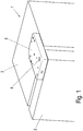
- a refrigerator 1 comprises a cabinet 3, on which a door 2 is rotatably mounted.
- a housing 5 with a Embodiment of a bearing arrangement according to the invention fixed.
- the bearing arrangement comprises a bearing axis 4 which is rotatably mounted in the housing and on which the door 2 is rotatably fixed.
- the housing 5 is fixed with the bearing arrangement on the top of the cabinet 3, but it is also possible to provide the bearing arrangement with the housing 5 on the bottom of the cabinet 3.
- a bearing arrangement is also arranged inside the cabinet 3, mounting on the outside having the advantage that retrofitting to existing refrigerators is possible.
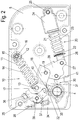
- the locking device 10 comprises a spring 11 designed as a compression spring, which is clamped between two end pieces 12 and 13.
- a first end piece 12 is rotatably mounted on the housing 5 about an axis 16.
- the end piece 13 is mounted about an axis 17 which is arranged on a rotatable actuating part 18.
- the rotatable actuating part 18 is rotatably mounted on the housing 5 about the axis 19.
- the spring 11 is guided around a sleeve 14 which can be pushed onto a rod 15 in order to be able to compensate for the length between the two end pieces 12 and 13.
- a damper 20 is also provided, which is designed as a linear pressure damper with a housing 21 and a piston rod 22.
- the piston rod 22 can be pushed into the housing 21, high damping forces being provided when the piston rod 22 is pushed in via a corresponding piston, while the piston rod 22 is pulled out smoothly.
- the housing 21 is fixed to a holder 24 which is rotatably mounted on the housing 5 about an axis 25.
- the piston rod 22 is connected on the opposite side via a holder 26 to a swivel part 28, the holder 26 being rotatably mounted about an axis 27.
- the swivel part 28 is rotatably mounted about the axis 19 on the housing 5, on which the actuating part 18 is also mounted, wherein the actuating part 18 and the swivel part 28 can be rotated independently of one another about the axis 19.
- a cam guide 30 is provided, which is arranged on the bearing axis 4 in a rotationally fixed manner.
- the Curve guide 30 comprises a plurality of control projections 31, 32 and 33, which act on the actuating part 18 and the pivoting part 28.
- a roller 40 is rotatably mounted on the actuating part 18, while a roller 41 is rotatably held on the pivoting part 28.
- the rollers can also be replaced by sliding elements, so that a process with as little friction as possible between the control projections and the actuating part or pivoting part 28 is ensured.
- a latching mechanism is provided in the housing 5 in order to latch the locking device 10 in a tensioned position, the latching mechanism comprising a pivotable latching pawl 35 which is mounted on the housing 5 such that it can rotate about the axis 38.
- the bearing axis 4 rotates the cam guide 30 counterclockwise, so that the first control projection 31 acts on the roller 40 in order to tension the spring 11 of the closing device 10.
- the damper 20 is released by rotating the control projection 31, whereby the pivoting part 28 rotates clockwise about the axis 19 until the pivoting part 28 stops 42 of the housing comes to rest.
- the pulling out of the piston rod 22 from the housing 21 and the associated pivoting of the pivoting part 28 takes place by means of the force of a spring 23 which is arranged between the holder 26 and the holder 24.
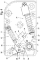
- the door 2 is arranged in an angular position of approximately 50 ° from the closed position.
- the damper 20 between the holder 24 and the holder 26 does not initially change its length when the closing device 10 is further tensioned by the control projection 31 acting on the roller 40 and thereby rotating the actuating part 18 further clockwise around the spring 11 of the closing device 10 compress.
- a control cam 34 of the locking mechanism When opening the door between an opening angle of 35 ° ( Figure 3 ) and 50 ° ( Figure 4 ) a control cam 34 of the locking mechanism also engages with an arm 37 of the locking pawl 35 so that it is rotated about the axis 38. As a result, a second arm 36 of the essentially V-shaped latch 35 is pivoted to the actuating part 18. The control curve 34 rotates the pawl 35 against the force of a spring 39, which biases the pawl 35 in the unlocked position.
- the locking pawl By slightly compressing the spring 11 of the locking device 10 and a pivoting of the locking pawl 35 by the control cam 34, the locking pawl can be moved into the unlocked position by the locking pawl 35 being pivoted about the axis 38 by the force of the spring 39.
- the control projection 31 comes into engagement with the roller 41 at a closing angle between 20 ° and 60 ° in order to pivot the pivoting part 28 counterclockwise and thereby move the damper 20 into the compressed position , As a result, damping forces are also generated when the door 2 is closed.
- the locking device 10 is effective since it was unlocked via the control cam 34, so that the spring 11 now rotates the actuating part 18 counterclockwise about the axis 19, the roller 40 running on the rear of the control projection.
- the actuating part 18 of the closing device 10 and the pivoting part 28 of the damper 20 are partly actuated via the same control projections 31, which form a common curve. It is of course also possible to provide two separate cam guides on the bearing axis 4, one cam guide being exclusively responsible for the actuating part 18 and the second cam guide exclusively for the pivoting part 28. Furthermore, it is possible that the actuating part 18 and the pivoting part 28 are not mounted on a common axis 19. Each of these components can also have its own axis.
- the shape of the control projections 31, 32 and 33 can be matched to the respective application. For example, it is possible to make the damping forces larger in an angular range shortly before reaching the maximum closed position than in an opening range between 20 ° and 30 °.
- the spring 11 of the closing device 10 can also be controlled via the cam guide 30 in such a way that the closing forces are kept low in the closed position in order to keep the forces on the seals low, while the closing forces are made larger in a slightly open area.
- the bearing axis 4 can be designed as a separate bearing axis. This means that the bearing axis, for example, during assembly is already installed in the door and the bearing arrangement is plugged onto the bearing axis, so that the bearing axis is indirectly connected to the cam guide.
- bearing arrangement can also be mounted on an underside of a cabinet, as shown in Figure 10 is shown. Then a door is mounted on the bearing axis 4 protruding upwards.
- the bearing arrangement shown can be used on a right or left side of a cabinet 3 without the need for special right or left components.
Landscapes
- Engineering & Computer Science (AREA)
- Mechanical Engineering (AREA)
- Closing And Opening Devices For Wings, And Checks For Wings (AREA)
- Refrigerator Housings (AREA)
Description
- Die vorliegende Erfindung betrifft eine Lageranordnung für eine Tür, insbesondere für Kühlschränke, nach dem Oberbgriff des Anspruches 1.
- Die
DE 20 2006 010 482 U1 offenbart eine Anordnung zur verschwenkbaren Lagerung einer Tür eines Kühl- oder Gefriergerätes. Die verschwenkbare Tür ist dabei mit einem Hebel gekoppelt, über den eine Schließeinrichtung und eine Dämpfungseinrichtung betätigt werden. Die Schließeinrichtung und die Dämpfungseinrichtung sind dabei über ein verschwenkbares Bauteil betätigbar, das durch die Tür über einen gewissen Schwenkbereich bewegt wird. Die starre Kopplung der Dämpfungseinrichtung mit der Schließeinrichtung über das Schwenkteil besitzt den Nachteil, dass keine flexible Anpassung der Dämpfungskräfte oder Schließkräfte an die jeweilige Tür erfolgen kann. Zudem können nur vergleichsweise geringe Dämpfungskräfte und Schließkräfte bewirkt werden. - Die
US 3,273,196 offenbart einen Beschlag für eine Schwingtür, bei dem benachbart zu einer vertikalen Achse eine Schließfeder und eine Dämpfervorrichtung angeordnet sind. Die Schießfeder spannt die Tür in Schließrichtung vor und wirkt dabei auf eine mit der Achse verbundene Kurvenführung. Die Dämpfervorrichtung wirkt ebenfalls mit einem Nocken auf eine Kurvenführung. - Es ist daher Aufgabe der vorliegenden Erfindung, eine Lageranordnung für eine Tür zu schaffen, die mit einer Schließeinrichtung und einem Dämpfer flexibel an den jeweiligen Einsatzzweck im Hinblick auf die Dämpfungskräfte und Schließkräfte angepasst werden kann.
- Diese Aufgabe wir mit einer Lageranordnung mit den Merkmalen des Anspruches 1 gelöst.
- Erfindungsgemäß wird zum Bewegen der Schließeinrichtung eine erste durch die Lagerachse bewegbare Kurvenführung und zum Bewegen des Dämpfers eine zweite durch die Lagerachse bewegbare Kurvenführung vorgesehen. Die Kurvenführungen können dabei entsprechende Steuervorsprünge aufweisen, die auf die Schließeinrichtung und/oder auf den Dämpfer einwirken. Dabei können für die Schließeinrichtung und den Dämpfer zwei getrennte Kurvenführungen eingesetzt werden, es ist aber auch möglich, eine einzige Kurvenführung vorzusehen, die dann sowohl auf die Schließeinrichtung als auch auf die Dämpfung einwirkt. Durch den Einsatz von Kurvenführungen können die Kräfte zum Schließen oder zum Dämpfen genauer eingestellt werden, da keine starre Kopplung mehr zwischen der Tür und der Schließeinrichtung und dem Dämpfer vorhanden ist, sondern die Kopplung über Kurvenführungen erfolgt, die bei einem Schwenken der Tür auf die Schließeinrichtung und den Dämpfer einwirken. Sowohl die Schließeinrichtung als auch der Dämpfer können dabei durch eine Feder gegen die Kurvenführung vorgespannt sein.
- Vorzugsweise sind die erste und die zweite Kurvenführung drehfest mit der Lagerachse verbunden, so dass ein besonders kompakter Aufbau möglich ist. Die erste und zweite Kurvenführung können dabei in axialer Richtung versetzt zueinander angeordnet sein oder durch eine einzige Scheibe gebildet sein, an der Steuervorsprünge ausgebildet sind.
- Gemäß einer bevorzugten Ausgestaltung betätigt die zweite Kurvenführung den Dämpfer zur Dämpfung der Tür sowohl in Schließrichtung vor Erreichen der Schließposition als auch in Öffnungsrichtung vor Erreichen der maximalen Öffnungsposition. Dadurch kann ein einziger Dämpfer eingesetzt werden, um eine Schließdämpfung und zudem eine Öffnungsdämpfung bereitzustellen. Der Dämpfer wird durch entsprechende Steuervorsprünge an der zweiten Kurvenführung betätigt, wobei die Öffnungsdämpfung vor Erreichen der maximalen Öffnungsposition stattfindet, die beispielsweise in einem Bereich zwischen 90° und 180° liegen kann. Die Öffnungsdämpfung und die Schließdämpfung können sich dabei über einen Schwenkbereich der Tür von jeweils wenigstens mindestens 5° erstrecken, vorzugsweise bei der Schießdämpfung zwischen 10° und 50° vor der Schließposition und bei der Öffnungsdämpfung zwischen 5° bis 25° vor der maximalen Öffnungsposition.
- Für eine kompakte Bauweise ist die Schließeinrichtung und der Dämpfer in einem Gehäuse aufgenommen, das wahlweise innerhalb eines Kühlschrankes oder außerhalb eingebaut werden kann.
- Der Dämpfer ist vorzugsweise als linearer Druckdämpfer ausgebildet, der beim Zusammendrücken eine höhere Dämpfungskraft bewirkt als beim Auseinanderziehen. Dadurch kann der Dämpfer zwar hohe Bremskräfte bei einer Schließ- oder Öffnungsdämpfung bereitstellen, bei einer Bewegung in gegenüberliegende Richtung ist der Dämpfer durch den Benutzer allerdings kaum oder nicht spürbar. Alternativ kann anstelle eines Druckdämpfers auch ein Zug- oder Rotationsdämpfer eingesetzt werden.
- Vorzugsweise ist der Dämpfer an einer Seite drehbar an dem Gehäuse gelagert und an der gegenüberliegenden Seite drehbar an einem Schwenkteil gehalten. Die zweite Kurvenführung kann dabei Steuervorsprünge aufweisen, die auf das Schwenkteil und/oder eine an dem Schwenkteil angeordnete Rolle wirken, um bei einer Bewegung der Tür den Dämpfer zu betätigen.
- Die Schließeinrichtung weist vorzugsweise eine Druckfeder auf, die zwischen zwei Endstücken eingespannt ist. Ein Endstück ist dabei drehbar an dem Gehäuse gelagert und das gegenüberliegende Endstück an einem drehbar gelagerten Betätigungsteil. Das drehbar gelagerte Betätigungsteil kann dann über mindestens einen Steuervorsprung an der ersten Kurvenführung bewegt werden, wobei an dem Betätigungsteil auch eine drehbare Rolle vorgesehen sein kann, auf die der mindestens eine Steuervorsprung einwirkt.
- Das Betätigungsteil zum Bewegen der Schließeinrichtung kann dabei unabhängig von dem Schwenkteil zum Betätigen des Dämpfers gedreht werden, wobei Schwenkteil und Betätigungsteil vorzugsweise um dieselbe Achse drehbar am Gehäuse gelagert sind.
- Ferner ist erfindungsgemäß ein Rastmechanismus vorgesehen, um die Schließeinrichtung bei geöffneter Tür in einem gespannten Zustand zu verrasten. Dadurch ist es möglich, nach dem Spannen der Schließeinrichtung die Tür in einem Freilauf zu bewegen, ohne dass durch die Schließeinrichtung Reib- oder Bremskräfte wirken. Der Rastmechanismus weist eine durch eine Steuerkurve betätigbare Rastklinke auf, wobei die Rastklinke durch eine Feder in die die Verrastung freigebende Position vorgespannt ist. Dadurch wird vermieden, dass durch die Sperrklinke versehentlich eine Blockierung der Tür erfolgt. Zudem ermöglicht der Rastmechanismus einen kompakten Aufbau, weil die Schließeinrichtung nur über einen Teil des Schenkweges der Tür bewegt wird, so dass nur für diesen Bewegungsbereich ein Bauraum zur Verfügung gestellt werden muss.
- Besonders vorteilhaft wirken die Kräfte der Schließeinrichtung und des Dämpfers in einer im Wesentlichen senkrechten Ebene zur Drehachse der Lagerachse der Lageranordnung. Die Lagerachse ist vorzugsweise im Wesentlichen vertikal ausgereichtet, während die Kräfte des Dämpfers und der Schließeinrichtung im Wesentlichen horizontal im eingebauten Zustand wirken. Dadurch ergibt sich eine besonders flache Bauweise der Lageranordnung.
- Die erfindungsgemäße Lageranordnung kann insbesondere für Haushaltsgeräte eingesetzt werden, beispielsweise für Kühlschränke oder Gefrierschränke. Zudem ist natürlich auch ein Einsatz für Möbel oder andere Haushaltsgeräte möglich.
- Die Erfindung wird nachfolgend anhand eines Ausführungsbeispiels mit Bezug auf die beigefügten Zeichnungen näher erläutert. Es zeigen:
- Figur 1
- eine perspektivische Ansicht eines Kühlschrankes mit einer erfindungsgemäßen Ausführungsform einer Lageranordnung;
- Figur 2
- eine Ansicht der Lageranordnung mit geschlossener Tür;
- Figur 3
- eine Ansicht der Lageranordnung mit geöffneter Tür in einem 35°-Winkel;
- Figur 4
- eine Ansicht der Lageranordnung mit geöffneter Tür in einem 50°-Winkel;
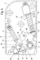
- Figur 5
- eine Ansicht der Lageranordnung mit geöffneter Tür in einem 67°-Winkel;
- Figur 6
- eine Ansicht der Lageranordnung mit geöffneter Tür in einem 100°-Winkel;
- Figur 7
- eine Ansicht der Lageranordnung mit geöffneter Tür in einem 155°-Winkel;
- Figur 8
- eine Ansicht der Lageranordnung mit geöffneter Tür in einem 180°-Winkel;
- Figur 9
- eine perspektivische Ansicht der Lageranordnung an einer Oberseite eines Schrankes, und
- Figur 10
- eine perspektivische Ansicht der Lageranordnung, die an einer Unterseite eines Schrankes 3 montiert ist.
- Ein Kühlschrank 1 umfasst einen Schrank 3, an dem eine Tür 2 drehbar gelagert ist. Hierfür ist an der Oberseite des Schrankes 3 ein Gehäuse 5 mit einer erfindungsgemäßen Ausführungsform einer Lageranordnung fixiert. Die Lageranordnung umfasst dabei eine Lagerachse 4, die drehbar im Gehäuse gelagert ist und an der die Tür 2 drehbar fixiert ist. In
Figur 1 ist das Gehäuse 5 mit der Lageranordnung an der Oberseite des Schrankes 3 fixiert, es ist aber auch möglich, die Lageranordnung mit dem Gehäuse 5 an der Unterseite des Schrankes 3 vorzusehen. In einer alternativen Ausführungsform ist eine Lageranordnung auch innerhalb des Schrankes 3 angeordnet, wobei eine Montage an der Außenseite den Vorteil hat, dass eine Nachrüstung bei bestehenden Kühlschränken möglich ist. - In
Figur 2 ist das Gehäuse 5 der Lageranordnung mit abgenommenem Gehäusedeckel gezeigt, so dass eine Schließeinrichtung 10 und ein Dämpfer 20 sichtbar sind. - Die Schließeinrichtung 10 umfasst eine als Druckfeder ausgebildete Feder 11, die zwischen zwei Endstücken 12 und 13 eingespannt ist. Ein erstes Endstück 12 ist dabei um eine Achse 16 drehbar an dem Gehäuse 5 gelagert. Auf der gegenüberliegenden Seite ist das Endstück 13 um eine Achse 17 gelagert, die an einem drehbaren Betätigungsteil 18 angeordnet ist. Das drehbare Betätigungsteil 18 ist um die Achse 19 an dem Gehäuse 5 drehbar gelagert. Die Feder 11 ist dabei um eine Hülse 14 geführt, die auf eine Stange 15 aufgeschoben werden kann, um einen Längenausgleich zwischen den beiden Endstücken 12 und 13 vornehmen zu können.
- In dem Gehäuse 5 ist ferner ein Dämpfer 20 vorgesehen, der als linearer Druckdämpfer mit einem Gehäuse 21 und einer Kolbenstange 22 ausgebildet ist. Die Kolbenstange 22 ist dabei in das Gehäuse 21 einschiebbar, wobei beim Einschieben der Kolbenstange 22 über einen entsprechenden Kolben hohe Dämpfungskräfte bereitgestellt werden, während das Herausziehen der Kolbenstange 22 leichtgängig erfolgt. Das Gehäuse 21 ist dabei an einem Halter 24 fixiert, der um eine Achse 25 drehbar an dem Gehäuse 5 gelagert ist. Die Kolbenstange 22 ist an der gegenüberliegenden Seite über einen Halter 26 mit einem Schwenkteil 28 verbunden, wobei der Halter 26 um eine Achse 27 drehbar gelagert ist. Das Schwenkteil 28 ist dabei um die Achse 19 drehbar an dem Gehäuse 5 gelagert, an dem auch das Betätigungsteil 18 gelagert ist, wobei das Betätigungsteil 18 und das Schwenkteil 28 unabhängig voneinander um die Achse 19 gedreht werden können.
- Zum Betätigen der Schließeinrichtung 10 und des Dämpfers 20 ist eine Kurvenführung 30 vorgesehen, die drehfest an der Lagerachse 4 angeordnet ist. Die Kurvenführung 30 umfasst mehrere Steuervorsprünge 31, 32 und 33, die auf das Betätigungsteil 18 und das Schwenkteil 28 einwirken. Hierfür ist an dem Betätigungsteil 18 eine Rolle 40 drehbar gelagert, während an dem Schwenkteil 28 eine Rolle 41 drehbar gehalten ist. Alternativ können die Rollen auch durch Gleitelemente ersetzt werden, so dass ein möglichst reibungsarmer Ablauf zwischen den Steuervorsprüngen und dem Betätigungsteil bzw Schwenkteil 28 gewährleistet ist.
- In dem Gehäuse 5 ist ferner noch ein Rastmechanismus vorgesehen, um die Schließeinrichtung 10 in einer gespannten Position zu verrasten, wobei der Rastmechanismus eine schwenkbare Rastklinke 35 umfasst, die um die Achse 38 drehbar an dem Gehäuse 5 gelagert ist.
- Wird die Tür 2 nun aus der Schließposition geöffnet, so wie dies in
Figur 3 gezeigt ist, dreht die Lagerachse 4 die Kurvenführung 30 gegen den Uhrzeigersinn, so dass der erste Steuervorsprung 31 auf die Rolle 40 wirkt, um die Feder 11 der Schließeinrichtung 10 zu spannen. Gleichzeitig wird in dem Schwenkbereich zwischen der Schließposition und einem Öffnungswinkel von zwischen 20° und 60° der Dämpfer 20 freigegeben, indem der Steuervorsprung 31 gedreht wird, wodurch sich das Schwenkteil 28 um die Achse 19 im Uhrzeigersinn dreht, bis das Schwenkteil 28 an einem Anschlag 42 des Gehäuses zur Anlage kommt. Das Herausziehen der Kolbenstange 22 aus dem Gehäuse 21 und das damit verbundene Verschwenken des Schwenkteils 28 erfolgt dabei mittels der Kraft einer Feder 23, die zwischen dem Halter 26 und dem Halter 24 angeordnet ist. - In
Figur 4 ist die Tür 2 in einer Winkelposition von etwa 50° von der Schließstellung entfernt angeordnet. Der Dämpfer 20 zwischen dem Halter 24 und dem Halter 26 ändert seine Länge zunächst nicht, wenn die Schließeinrichtung 10 weiter gespannt wird, indem der Steuervorsprung 31 auf die Rolle 40 wirkt und dabei das Betätigungsteil 18 weiter im Uhrzeigersinn dreht, um die Feder 11 der Schließeinrichtung 10 zu komprimieren. - Beim Öffnen der Tür zwischen einem Öffnungswinkel von 35° (
Figur 3 ) und 50° (Figur 4 ) gelangt zudem eine Steuerkurve 34 des Rastmechanismus in Eingriff mit einem Arm 37 der Rastklinke 35, so dass diese um die Achse 38 gedreht wird. Dadurch wird ein zweiter Arm 36 der im Wesentlichen V-förmig ausgebildeten Rastklinke 35 zu dem Betätigungsteil 18 verschwenkt. Die Steuerkurve 34 dreht dabei die Rastklinke 35 gegen die Kraft einer Feder 39, die die Rastklinke 35 in die entriegelte Position vorspannt. - Wird nun die Tür 2 weiter in Öffnungsrichtung verschwenkt, wird die in
Figur 5 gezeigte Position durchlaufen, an der der Arm 36 in Eingriff mit dem Endstück 13 gelangt, um die Schließeinrichtung 10 zu verrasten. Die Steuerkurve 34 verlässt nun den Arm 37, wobei der Steuervorsprung 31 so ausgebildet ist, dass die Feder 11 beim Verrasten geringfügig entspannt, um an dem Arm 36 zu verrasten, so dass die Rolle 40 von dem Steuervorsprung 31 abgehoben werden kann. - Wird nun die Tür 2 weiter in Öffnungsrichtung bewegt, beispielsweise bis zu einem Öffnungswinkel von etwa 100° (
Figur 6 ), bewegt sich die Tür 2 im Freilauf, d. h. weder die Schließeinrichtung 10 noch der Dämpfer 20 üben Schließ- oder Öffnungskräfte auf die Tür 2 aus. Dies liegt darin begründet, dass die Schließeinrichtung 10 an der Rastklinke 35 verrastet ist und stationär verbleibt, während der Dämpfer 20 an dem Anschlag 42 anliegt und ebenfalls stationär angeordnet ist. - Wird nun die Tür 2 weiter in Öffnungsrichtung bewegt, gelangt ein weiterer Steuervorsprung 33 der Kurvenführung 30 in Eingriff mit dem Schwenkteil 28 und/oder der Rolle 41, um das Schwenkteil 28 gegen den Uhrzeigersinn zu drehen. Dadurch wird der Dämpfer 20 zusammengedrückt und die Kolbenstange 22 fährt in das Gehäuse 21 ein, wodurch Dämpfungskräfte erzeugt werden. Bei einer Bewegung von einem Öffnungswinkel von etwa 155° (
Figur 7 ) bis zur maximalen Öffnungsposition von etwa 180° (Figur 8 ), wird der Dämpfer 20 dadurch zusammengedrückt. Die Schließeinrichtung 10 ist nach wie vor in der verrasteten Position und übt somit keine Kräfte auf die Tür 2 aus. Öffnungswinkel maximal 90° bis 180°. - Wird die Tür 2 nun aus der maximalen Öffnungsposition der
Figur 8 in Schließrichtung bewegt, wird zunächst der Dämpfer 20 von der zusammengedrückten Position wieder auseinander bewegt, wobei die Bewegung durch die Feder 23 vorgenommen wird, so dass der Benutzer keine Kräfte durch das Ausfahren des Dämpfers 20 beim Schließen der Tür 2 spürt. Die Tür 2 wird nun weiter in Schließrichtung bewegt, bis bei einem Öffnungswinkel von etwa 60° bis 70° der Steuervorsprung 31 gegen die Rolle 40 des Betätigungsteil 18 zur Anlage kommt und gleichzeitig die Steuerkurve 34 an dem Arm 37 der Rastklinke 35 anstößt. Durch ein geringfügiges Zusammendrücken der Feder 11 der Schließeinrichtung 10 und ein Verschwenken der Rastklinke 35 durch die Steuerkurve 34 kann die Rastklinke in die entriegelte Position bewegt werden, indem die Rastklinke 35 um die Achse 38 durch die Kraft der Feder 39 verschwenkt wird. - Wird die Tür 2 nun weiter in Schließrichtung bewegt, gelangt bei einem Schließwinkel zwischen 20° bis 60° der Steuervorsprung 31 in Eingriff mit der Rolle 41, um das Schwenkteil 28 gegen den Uhrzeigersinn zu verschwenken und dadurch den Dämpfer 20 in die zusammengedrückte Position zu bewegen. Dadurch werden beim Schließen der Tür 2 ebenfalls Dämpfungskräfte erzeugt. Gleichzeitig ist die Schließeinrichtung 10 wirksam, da diese über die Steuerkurve 34 entriegelt wurde, so dass nun die Feder 11 das Betätigungsteil 18 gegen den Uhrzeigersinn um die Achse 19 dreht, wobei die Rolle 40 auf der Rückseite des Steuervorsprunges abläuft.
- Wird aufgrund von Fertigungstoleranzen die Tür 2 über einen Winkel von 0° hinaus geschlossen, ist dies mit der gezeigten Lageranordnung ebenfalls möglich, wobei hierfür an der Kurvenführung 30 ein weiterer Steuervorsprung 32 vorgesehen ist, um die maximalen Schließkräfte gering zu halten.
- In dem gezeigten Ausführungsbeispiel wird das Betätigungsteil 18 der Schließeinrichtung 10 und das Schwenkteil 28 des Dämpfers 20 teilweise über die gleichen Steuervorsprünge 31 betätigt, die eine gemeinsame Kurvenführung ausbilden. Es ist natürlich auch möglich, auf der Lagerachse 4 zwei getrennte Kurvenführungen vorzusehen, wobei eine Kurvenführung ausschließlich für das Betätigungsteil 18 und die zweite Kurvenführung ausschließlich für das Schwenkteil 28 zuständig ist. Des Weiteren ist es möglich, dass das Betätigungsteil 18 und das Schwenkteil 28 nicht über eine gemeinsame Achse 19 gelagert sind. Jedes dieser Bauteile kann auch eine eigene Achse aufweisen.
- Die Form der Steuervorsprünge 31, 32 und 33 kann auf den jeweiligen Einsatzzweck abgestimmt sein. Beispielsweise ist es möglich, die Dämpfungskräfte in einem Winkelbereich kurz vor Erreichen der maximalen Schließposition größer auszugestalten als in einem Öffnungsbereich zwischen 20° und 30°. Zudem kann auch die Feder 11 der Schließeinrichtung 10 über die Kurvenführung 30 so angesteuert werden, dass die Schließkräfte in der Schließposition gering gehalten werden, um die Kräfte auf die Dichtungen gering zu halten, während die Schließkräfte in einem leicht geöffneten Bereich größer ausgestaltet sind. Je nach Ausführungsform der Erfindung kann die Lagerachse 4 als separate Lagerachse ausgeführt sein. Das heißt, dass die Lagerachse z.B. bei der Montage bereits in der Tür angebracht ist und die Lageranordnung auf die Lagerachse aufgesteckt wird, so dass die Lagerachse mittelbar mit der Kurvenführung verbunden ist.
- In
Figur 9 ist die Lageranordnung mit dem Gehäuse 5 an einer Oberseite eines Schrankes 3 montiert und die Lagerachse 4 steht nach unten hervor. An der Lagerachse 4 mit nicht kreisförmigen Querschnitt kann dann eine Tür montiert werden, die durch die Lageranordnung entsprechenden Dämpfungs-, Öffnungs- und Schließkräften ausgesetzt wird. - Ferner kann die Lageranordnung auch an einer Unterseite eines Schrankes montiert werden, wie dies in
Figur 10 dargestellt ist. Dann wird ein Tür an der nach oben hervorstehenden Lagerachse 4 montiert. - Die gezeigte Lageranordnung kann einer an einer rechten oder linken Seite eines Schrankes 3 eingesetzt werden, ohne dass spezielle rechte oder linke Bauteile benötigt werden.
-
- 1
- Kühlschrank
- 2
- Tür
- 3
- Schrank
- 4
- Lagerachse
- 5
- Gehäuse
- 10
- Schließeinrichtung
- 11
- Feder
- 12
- Endstück
- 13
- Endstück
- 14
- Hülse
- 15
- Stange
- 16
- Achse
- 17
- Achse
- 18
- Betätigungsteil
- 19
- Achse
- 20
- Dämpfer
- 21
- Gehäuse
- 22
- Kolbenstange
- 23
- Feder
- 24
- Halter
- 25
- Achse
- 26
- Halter
- 27
- Achse
- 28
- Schwenkteil
- 30
- Kurvenführung
- 31
- Steuervorsprung
- 32
- Steuervorsprung
- 33
- Steuervorsprung
- 34
- Steuerkurve
- 35
- Rastklinke
- 36
- Arm
- 37
- Arm
- 38
- Achse
- 39
- Feder
- 40
- Rolle
- 41
- Rolle
- 42
- Anschlag
Claims (13)
- Lageranordnung für eine Tür (2), insbesondere für Kühlschränke oder Gefrierschränke, mit einer Lagerachse (4) zur drehbaren Lagerung der Tür (2), einer Schließeinrichtung (10), mittels der die Tür (2) durch die Kraft eines Kraftspeichers (11) über einen gewissen Schwenkbereich in Schließrichtung bewegbar ist, einem Dämpfer (20) zum Dämpfen einer Schwenkbewegung der Tür (2) über mindestens einen Schwenkbereich, wobei die Schließeinrichtung (10) und der Dämpfer (20) in einer im Wesentlichen senkrechten Ebene zur Drehachse der Lagerachse (4) ausgerichtet sind, wobei mittelbar oder unmittelbar an der Lagerachse (4) eine Kurvenführung (30) angeordnet ist, wobei zum Bewegen der Schließeinrichtung (10) eine durch die Lagerachse (4) bewegbare erste Kurvenführung ist und zum Bewegen des Dämpfers (20) wenigstens eine zweite durch die Lagerachse (4) bewegbare Kurvenführung vorgesehen ist, dadurch gekennzeichnet, dass ein Rastmechanismus vorgesehen ist, um die Schließeinrichtung (10) bei geöffneter Tür (2) in einem gespannten Zustand zu verrasten, wobei der Rastmechanismus eine durch eine mittelbar oder unmittelbar an der Lagerachse angeordnete Steuerkurve (34) der Lageranordnung betätigbare Rastklinke (35) aufweist und die Rastklinke (35) durch eine Feder (39) des Rastmechanismus in der die Verrastung freigebende Position vorgespannt ist.
- Lageranordnung nach Anspruch 1, dadurch gekennzeichnet, dass die erste und die zweite Kurvenführung (30) drehfest mit der Lagerachse (4) verbunden sind.
- Lageranordnung nach Anspruch 1 oder 2, dadurch gekennzeichnet, dass die erste und zweite Kurvenführung (30) Steuervorsprünge (31, 32, 33) aufweisen, die auf die Schließeinrichtung (10) und/oder den Dämpfer (20) einwirken können.
- Lageranordnung nach einem der vorhergehenden Ansprüche, dadurch gekennzeichnet, dass die zweite Kurvenführung den Dämpfer (20) zur Dämpfung der Tür (2) sowohl in Schließrichtung vor Erreichen der Schließposition als auch in Öffnungsrichtung vor Erreichen der maximalen Öffnungsposition betätigt.
- Lageranordnung nach einem der vorhergehenden Ansprüche, dadurch gekennzeichnet, dass die Schließeinrichtung (10) und der Dämpfer (20) in einem Gehäuse (5) aufgenommen sind.
- Lageranordnung nach Anspruch 5, dadurch gekennzeichnet, dass der Dämpfer (20) an einer Seite drehbar an dem Gehäuse (5) gelagert ist und an der gegenüberliegenden Seite drehbar an einem Schwenkteil (28) gehalten ist.
- Lageranordnung nach Anspruch 6, dadurch gekennzeichnet, dass die zweite Kurvenführung Steuervorsprünge (31, 32, 33) aufweist, die auf das Schwenkteil (28) oder eine an dem Schwenkteil (28) angeordnete Rolle (41) oder Gleitelement wirken.
- Lageranordnung nach einem der vorhergehenden Ansprüche, dadurch gekennzeichnet, dass die Schließeinrichtung (10) eine Feder (11), vorzugsweise eine Druckfeder (11),aufweist, die zwischen zwei Endstücken (12, 13) eingespannt ist.
- Lageranordnung nach Anspruch 8, dadurch gekennzeichnet, dass ein Endstück (12) drehbar an dem Gehäuse (5) gelagert ist und das gegenüberliegende Endstück (13) an einem drehbar gelagerten Betätigungsteil (18) angeordnet ist.
- Lageranordnung nach Anspruch 9, dadurch gekennzeichnet, dass das drehbar gelagerte Betätigungsteil (18) über mindestens einen Steuervorsprung (31, 32) an der ersten Kurvenführung (30) bewegbar ist, wobei an dem Betätigungsteil (18) eine drehbare Rolle (40) oder ein Gleitelement vorgesehen sein kann, auf die der mindestens eine Steuervorsprung (31, 32) wirkt.
- Lageranordnung nach einem der vorhergehenden Ansprüche, dadurch gekennzeichnet, dass der Dämpfer (20) als linearer Druckdämpfer ausgebildet ist, der beim Zusammendrücken eine höhere Dämpfungskraft bewirkt als beim Auseinanderziehen.
- Kühl- oder Gefrierschrank (1), mit mindestens einer verschwenkbaren Tür (2), die über mindestens eine Lageranordnung nach einem der vorhergehenden Ansprüche an einem Schrank (3) gehalten ist.
- Kühl- oder Gefrierschrank nach Anspruch 12, dadurch gekennzeichnet, dass die Lageranordnung an einer Außenseite des Schrankes (3) festgelegt ist.
Priority Applications (1)
| Application Number | Priority Date | Filing Date | Title |
|---|---|---|---|
| PL15704295T PL3105396T3 (pl) | 2014-02-13 | 2015-02-11 | Układ łożyskowy dla drzwi |
Applications Claiming Priority (2)
| Application Number | Priority Date | Filing Date | Title |
|---|---|---|---|
| DE102014101849.4A DE102014101849A1 (de) | 2014-02-13 | 2014-02-13 | Lageranordnung für eine Tür |
| PCT/EP2015/052808 WO2015121271A1 (de) | 2014-02-13 | 2015-02-11 | Lageranordnung für eine tür |
Publications (2)
| Publication Number | Publication Date |
|---|---|
| EP3105396A1 EP3105396A1 (de) | 2016-12-21 |
| EP3105396B1 true EP3105396B1 (de) | 2019-12-18 |
Family
ID=52469837
Family Applications (1)
| Application Number | Title | Priority Date | Filing Date |
|---|---|---|---|
| EP15704295.3A Active EP3105396B1 (de) | 2014-02-13 | 2015-02-11 | Lageranordnung für eine tür |
Country Status (11)
| Country | Link |
|---|---|
| US (1) | US9903146B2 (de) |
| EP (1) | EP3105396B1 (de) |
| JP (1) | JP6611360B2 (de) |
| KR (1) | KR102251484B1 (de) |
| CN (1) | CN105960500B (de) |
| AU (1) | AU2015217669B2 (de) |
| DE (1) | DE102014101849A1 (de) |
| ES (1) | ES2779067T3 (de) |
| PL (1) | PL3105396T3 (de) |
| RU (1) | RU2674189C2 (de) |
| WO (1) | WO2015121271A1 (de) |
Cited By (1)
| Publication number | Priority date | Publication date | Assignee | Title |
|---|---|---|---|---|
| EP4450745A1 (de) * | 2023-04-20 | 2024-10-23 | LG Electronics Inc. | Kühlschrank |
Families Citing this family (10)
| Publication number | Priority date | Publication date | Assignee | Title |
|---|---|---|---|---|
| CN108265477B (zh) * | 2016-12-30 | 2024-11-22 | 天津海尔洗涤电器有限公司 | 一种阻尼器及其洗衣机 |
| DE102017126367A1 (de) * | 2017-11-10 | 2019-05-16 | Hettich-Oni Gmbh & Co. Kg | Klappenbeschlag für ein Möbel, Seitenwand eines Möbelkorpus und Möbel mit einer Seitenwand |
| DE102017126366A1 (de) * | 2017-11-10 | 2019-05-16 | Hettich-Oni Gmbh & Co. Kg | Klappenbeschlag für ein Möbel, Seitenwand eines Möbelkorpus und Möbel mit einer Seitenwand |
| CN108061423B (zh) * | 2017-12-30 | 2020-10-30 | 青岛海尔股份有限公司 | 一种门体铰链机构及具有该门体铰链机构的冰箱 |
| CN108193966B (zh) * | 2017-12-30 | 2021-03-23 | 海尔智家股份有限公司 | 一种门体铰链机构及具有该门体铰链机构的冰箱 |
| CN112739881B (zh) * | 2018-09-14 | 2022-07-19 | C.M.I.铰链机械工业有限公司 | 具有终端速度衰减的家电和陈设的铰链装置 |
| CN111140114B (zh) * | 2020-03-10 | 2021-05-14 | 长虹美菱股份有限公司 | 一种冰箱铰链组件 |
| US11536070B2 (en) * | 2020-06-04 | 2022-12-27 | Whirlpool Corporation | Dish treating appliance with a door opener |
| IT202200000212A1 (it) * | 2022-01-10 | 2023-07-10 | Oreste Lanzani | Cerniera perfezionata in particolare per un elettrodomestico |
| CN116201432B (zh) * | 2023-03-20 | 2026-05-08 | 东莞动源机电科技有限公司 | 一种柜门开合省力装置 |
Citations (3)
| Publication number | Priority date | Publication date | Assignee | Title |
|---|---|---|---|---|
| GB408782A (en) * | 1933-02-15 | 1934-04-19 | Newman William & Sons Ltd | Improvements in door closing and checking appliances |
| GB925095A (en) * | 1960-09-02 | 1963-05-01 | Ver Baubeschlag Gretsch Co | Improvements in or relating to door closing and checking devices |
| US20090033189A1 (en) * | 2007-08-03 | 2009-02-05 | Dorma Gmbh + Co. Kg | Door Actuation Device for Actuating the Door of a Refrigerator/Freezer Cabinet |
Family Cites Families (17)
| Publication number | Priority date | Publication date | Assignee | Title |
|---|---|---|---|---|
| US2603818A (en) * | 1948-04-12 | 1952-07-22 | George W Houlsby Jr | Door check mechanism |
| GB1050496A (de) * | 1963-12-24 | 1900-01-01 | ||
| DE1807399A1 (de) * | 1968-11-07 | 1970-05-27 | Doerken & Mankel Kg | Selbsttaetiger Tuerschliesser |
| FR2045128A5 (de) * | 1969-06-04 | 1971-02-26 | Verrieres Appliq Et | |
| DE2010580A1 (de) * | 1970-03-06 | 1971-09-16 | Vereinigte Baubeschlagfabriken Gretsch & Co Gmbh, 7250 Leonberg | Türschließer |
| US3773311A (en) * | 1971-09-27 | 1973-11-20 | Hartwell Corp | Overhead door control device |
| GB1344945A (en) * | 1972-01-06 | 1974-01-23 | Gibbons Ld James | Doorclosing mechanism |
| DE2522410A1 (de) * | 1975-05-21 | 1977-01-20 | Ver Baubeschlag Gretsch Co | Bodentuerschliesser |
| DE2620386C3 (de) * | 1976-05-08 | 1980-08-28 | Vereinigte Baubeschlagfabriken Gretsch & Co Gmbh, 7250 Leonberg | Feststellvorrichtung für einen Türschließer |
| DE2608671A1 (de) * | 1976-03-03 | 1977-09-08 | Dorma Baubeschlag | Selbsttaetiger tuerschliesser |
| JP4076528B2 (ja) * | 2004-08-30 | 2008-04-16 | 日立アプライアンス株式会社 | 冷蔵庫扉閉鎖装置 |
| CN101093131B (zh) * | 2006-06-21 | 2010-12-29 | 海尔集团公司 | 电冰箱 |
| DE202006010482U1 (de) | 2006-07-06 | 2007-11-08 | Liebherr-Hausgeräte Lienz Gmbh | Anordnung zur schwenkbaren Lagerung einer Tür oder Klappe sowie Kühl- und/oder Gefriergeräte mit einer derartigen Anordnung |
| DE202007005957U1 (de) * | 2007-02-19 | 2008-06-26 | Liebherr-Hausgeräte Ochsenhausen GmbH | Kühl- und/oder Gefriergerät |
| DE102009034742A1 (de) * | 2009-07-24 | 2011-02-03 | Dorma Gmbh + Co. Kg | Türschließer |
| GB2479145A (en) * | 2010-03-29 | 2011-10-05 | Ingersoll Rand Security Technologies Ltd | Door closer having two springs |
| WO2015111026A1 (en) * | 2014-01-27 | 2015-07-30 | In & Tec S.R.L. | Low-bulkiness hinge |
-
2014
- 2014-02-13 DE DE102014101849.4A patent/DE102014101849A1/de not_active Withdrawn
-
2015
- 2015-02-11 AU AU2015217669A patent/AU2015217669B2/en not_active Ceased
- 2015-02-11 KR KR1020167022852A patent/KR102251484B1/ko not_active Expired - Fee Related
- 2015-02-11 EP EP15704295.3A patent/EP3105396B1/de active Active
- 2015-02-11 CN CN201580007420.5A patent/CN105960500B/zh active Active
- 2015-02-11 JP JP2016551802A patent/JP6611360B2/ja not_active Expired - Fee Related
- 2015-02-11 RU RU2016133848A patent/RU2674189C2/ru active
- 2015-02-11 WO PCT/EP2015/052808 patent/WO2015121271A1/de not_active Ceased
- 2015-02-11 ES ES15704295T patent/ES2779067T3/es active Active
- 2015-02-11 US US15/118,317 patent/US9903146B2/en not_active Expired - Fee Related
- 2015-02-11 PL PL15704295T patent/PL3105396T3/pl unknown
Patent Citations (3)
| Publication number | Priority date | Publication date | Assignee | Title |
|---|---|---|---|---|
| GB408782A (en) * | 1933-02-15 | 1934-04-19 | Newman William & Sons Ltd | Improvements in door closing and checking appliances |
| GB925095A (en) * | 1960-09-02 | 1963-05-01 | Ver Baubeschlag Gretsch Co | Improvements in or relating to door closing and checking devices |
| US20090033189A1 (en) * | 2007-08-03 | 2009-02-05 | Dorma Gmbh + Co. Kg | Door Actuation Device for Actuating the Door of a Refrigerator/Freezer Cabinet |
Cited By (1)
| Publication number | Priority date | Publication date | Assignee | Title |
|---|---|---|---|---|
| EP4450745A1 (de) * | 2023-04-20 | 2024-10-23 | LG Electronics Inc. | Kühlschrank |
Also Published As
| Publication number | Publication date |
|---|---|
| AU2015217669A1 (en) | 2016-07-28 |
| KR102251484B1 (ko) | 2021-05-12 |
| CN105960500B (zh) | 2018-05-01 |
| RU2016133848A (ru) | 2018-03-16 |
| KR20160124114A (ko) | 2016-10-26 |
| AU2015217669B2 (en) | 2019-01-03 |
| EP3105396A1 (de) | 2016-12-21 |
| DE102014101849A1 (de) | 2015-08-13 |
| US9903146B2 (en) | 2018-02-27 |
| JP6611360B2 (ja) | 2019-11-27 |
| US20170175429A1 (en) | 2017-06-22 |
| JP2017511848A (ja) | 2017-04-27 |
| CN105960500A (zh) | 2016-09-21 |
| RU2674189C2 (ru) | 2018-12-05 |
| PL3105396T3 (pl) | 2020-06-01 |
| RU2016133848A3 (de) | 2018-08-23 |
| ES2779067T3 (es) | 2020-08-13 |
| WO2015121271A1 (de) | 2015-08-20 |
Similar Documents
| Publication | Publication Date | Title |
|---|---|---|
| WO2015121271A1 (de) | Lageranordnung für eine tür | |
| DE202018105095U1 (de) | Tür- und Treppenschutzgitter mit ausrollbarer Trennwand | |
| DE69808823T2 (de) | Schliessfolgeregler für eine zweiflügelige Tür | |
| EP3336292B1 (de) | Verfahren zum betätigen eines türschlosses und türschloss | |
| DE102011050053B4 (de) | Scharnier | |
| DE102011083512A1 (de) | Haushaltsgerät mit einem Aufnahmeraum und einer Tür zum Verschließen des Aufnahmeraums, sowie Verfahren zum Betätigen einer Tür eines Haushaltsgeräts | |
| DE102012111085B4 (de) | Türöffner | |
| DE102009029023A1 (de) | Kraftfahrzeugschloss | |
| DE202004021727U1 (de) | Scharnier | |
| EP3143227B1 (de) | Lageranordnung für eine tür | |
| EP2949842B1 (de) | Türgriffanordnung für ein kraftfahrzeug | |
| EP3487359B1 (de) | Ausstossvorrichtung für ein bewegbares möbelteil und möbel | |
| DE202011105510U1 (de) | Türöffner mit Sperr-Riegel | |
| DE102012009067B3 (de) | Aufschlagsicherer Türöffner | |
| DE102011119333B3 (de) | Feststellvorrichtung für eine Tür, vorzugsweise mit Türschließer | |
| DE102016118139A1 (de) | Trennscheibe für Paniknuss | |
| DE10211704C1 (de) | Verschluß für Kühlräume | |
| EP1672153B1 (de) | Schloss mit Riegel und Riegelantrieb | |
| DE3916836C1 (en) | Actuating mechanism for sealing door esp. for EM screening - has rotating shaft with connecting lever closing door against stop-bands on door frame | |
| DE102017119252A1 (de) | Funktionskomponente einer Kraftfahrzeugschlossanordnung | |
| EP4174261B1 (de) | Türverschluss zum verschliessen einer tür | |
| DE102012010438B4 (de) | Türöffner mit Sperr-Riegel | |
| DE102016010445B4 (de) | Flügelschloss | |
| DE102016122885A1 (de) | Verschluss für eine Klappe, Tür, Schublade oder dergleichen | |
| EP3122964B1 (de) | Schloss für tür oder fenster |
Legal Events
| Date | Code | Title | Description |
|---|---|---|---|
| PUAI | Public reference made under article 153(3) epc to a published international application that has entered the european phase |
Free format text: ORIGINAL CODE: 0009012 |
|
| STAA | Information on the status of an ep patent application or granted ep patent |
Free format text: STATUS: REQUEST FOR EXAMINATION WAS MADE |
|
| 17P | Request for examination filed |
Effective date: 20160712 |
|
| AK | Designated contracting states |
Kind code of ref document: A1 Designated state(s): AL AT BE BG CH CY CZ DE DK EE ES FI FR GB GR HR HU IE IS IT LI LT LU LV MC MK MT NL NO PL PT RO RS SE SI SK SM TR |
|
| AX | Request for extension of the european patent |
Extension state: BA ME |
|
| DAX | Request for extension of the european patent (deleted) | ||
| STAA | Information on the status of an ep patent application or granted ep patent |
Free format text: STATUS: EXAMINATION IS IN PROGRESS |
|
| 17Q | First examination report despatched |
Effective date: 20171124 |
|
| GRAP | Despatch of communication of intention to grant a patent |
Free format text: ORIGINAL CODE: EPIDOSNIGR1 |
|
| STAA | Information on the status of an ep patent application or granted ep patent |
Free format text: STATUS: GRANT OF PATENT IS INTENDED |
|
| INTG | Intention to grant announced |
Effective date: 20190731 |
|
| GRAS | Grant fee paid |
Free format text: ORIGINAL CODE: EPIDOSNIGR3 |
|
| GRAA | (expected) grant |
Free format text: ORIGINAL CODE: 0009210 |
|
| STAA | Information on the status of an ep patent application or granted ep patent |
Free format text: STATUS: THE PATENT HAS BEEN GRANTED |
|
| AK | Designated contracting states |
Kind code of ref document: B1 Designated state(s): AL AT BE BG CH CY CZ DE DK EE ES FI FR GB GR HR HU IE IS IT LI LT LU LV MC MK MT NL NO PL PT RO RS SE SI SK SM TR |
|
| REG | Reference to a national code |
Ref country code: CH Ref legal event code: EP |
|
| REG | Reference to a national code |
Ref country code: IE Ref legal event code: FG4D Free format text: LANGUAGE OF EP DOCUMENT: GERMAN |
|
| REG | Reference to a national code |
Ref country code: DE Ref legal event code: R096 Ref document number: 502015011252 Country of ref document: DE |
|
| REG | Reference to a national code |
Ref country code: AT Ref legal event code: REF Ref document number: 1214770 Country of ref document: AT Kind code of ref document: T Effective date: 20200115 |
|
| REG | Reference to a national code |
Ref country code: NL Ref legal event code: MP Effective date: 20191218 |
|
| PG25 | Lapsed in a contracting state [announced via postgrant information from national office to epo] |
Ref country code: FI Free format text: LAPSE BECAUSE OF FAILURE TO SUBMIT A TRANSLATION OF THE DESCRIPTION OR TO PAY THE FEE WITHIN THE PRESCRIBED TIME-LIMIT Effective date: 20191218 Ref country code: BG Free format text: LAPSE BECAUSE OF FAILURE TO SUBMIT A TRANSLATION OF THE DESCRIPTION OR TO PAY THE FEE WITHIN THE PRESCRIBED TIME-LIMIT Effective date: 20200318 Ref country code: SE Free format text: LAPSE BECAUSE OF FAILURE TO SUBMIT A TRANSLATION OF THE DESCRIPTION OR TO PAY THE FEE WITHIN THE PRESCRIBED TIME-LIMIT Effective date: 20191218 Ref country code: LV Free format text: LAPSE BECAUSE OF FAILURE TO SUBMIT A TRANSLATION OF THE DESCRIPTION OR TO PAY THE FEE WITHIN THE PRESCRIBED TIME-LIMIT Effective date: 20191218 Ref country code: LT Free format text: LAPSE BECAUSE OF FAILURE TO SUBMIT A TRANSLATION OF THE DESCRIPTION OR TO PAY THE FEE WITHIN THE PRESCRIBED TIME-LIMIT Effective date: 20191218 Ref country code: NO Free format text: LAPSE BECAUSE OF FAILURE TO SUBMIT A TRANSLATION OF THE DESCRIPTION OR TO PAY THE FEE WITHIN THE PRESCRIBED TIME-LIMIT Effective date: 20200318 Ref country code: GR Free format text: LAPSE BECAUSE OF FAILURE TO SUBMIT A TRANSLATION OF THE DESCRIPTION OR TO PAY THE FEE WITHIN THE PRESCRIBED TIME-LIMIT Effective date: 20200319 |
|
| REG | Reference to a national code |
Ref country code: LT Ref legal event code: MG4D |
|
| PG25 | Lapsed in a contracting state [announced via postgrant information from national office to epo] |
Ref country code: HR Free format text: LAPSE BECAUSE OF FAILURE TO SUBMIT A TRANSLATION OF THE DESCRIPTION OR TO PAY THE FEE WITHIN THE PRESCRIBED TIME-LIMIT Effective date: 20191218 Ref country code: RS Free format text: LAPSE BECAUSE OF FAILURE TO SUBMIT A TRANSLATION OF THE DESCRIPTION OR TO PAY THE FEE WITHIN THE PRESCRIBED TIME-LIMIT Effective date: 20191218 |
|
| PG25 | Lapsed in a contracting state [announced via postgrant information from national office to epo] |
Ref country code: AL Free format text: LAPSE BECAUSE OF FAILURE TO SUBMIT A TRANSLATION OF THE DESCRIPTION OR TO PAY THE FEE WITHIN THE PRESCRIBED TIME-LIMIT Effective date: 20191218 |
|
| PG25 | Lapsed in a contracting state [announced via postgrant information from national office to epo] |
Ref country code: PT Free format text: LAPSE BECAUSE OF FAILURE TO SUBMIT A TRANSLATION OF THE DESCRIPTION OR TO PAY THE FEE WITHIN THE PRESCRIBED TIME-LIMIT Effective date: 20200513 Ref country code: NL Free format text: LAPSE BECAUSE OF FAILURE TO SUBMIT A TRANSLATION OF THE DESCRIPTION OR TO PAY THE FEE WITHIN THE PRESCRIBED TIME-LIMIT Effective date: 20191218 Ref country code: CZ Free format text: LAPSE BECAUSE OF FAILURE TO SUBMIT A TRANSLATION OF THE DESCRIPTION OR TO PAY THE FEE WITHIN THE PRESCRIBED TIME-LIMIT Effective date: 20191218 Ref country code: RO Free format text: LAPSE BECAUSE OF FAILURE TO SUBMIT A TRANSLATION OF THE DESCRIPTION OR TO PAY THE FEE WITHIN THE PRESCRIBED TIME-LIMIT Effective date: 20191218 Ref country code: EE Free format text: LAPSE BECAUSE OF FAILURE TO SUBMIT A TRANSLATION OF THE DESCRIPTION OR TO PAY THE FEE WITHIN THE PRESCRIBED TIME-LIMIT Effective date: 20191218 |
|
| REG | Reference to a national code |
Ref country code: ES Ref legal event code: FG2A Ref document number: 2779067 Country of ref document: ES Kind code of ref document: T3 Effective date: 20200813 |
|
| PG25 | Lapsed in a contracting state [announced via postgrant information from national office to epo] |
Ref country code: SM Free format text: LAPSE BECAUSE OF FAILURE TO SUBMIT A TRANSLATION OF THE DESCRIPTION OR TO PAY THE FEE WITHIN THE PRESCRIBED TIME-LIMIT Effective date: 20191218 Ref country code: IS Free format text: LAPSE BECAUSE OF FAILURE TO SUBMIT A TRANSLATION OF THE DESCRIPTION OR TO PAY THE FEE WITHIN THE PRESCRIBED TIME-LIMIT Effective date: 20200418 Ref country code: SK Free format text: LAPSE BECAUSE OF FAILURE TO SUBMIT A TRANSLATION OF THE DESCRIPTION OR TO PAY THE FEE WITHIN THE PRESCRIBED TIME-LIMIT Effective date: 20191218 |
|
| REG | Reference to a national code |
Ref country code: DE Ref legal event code: R097 Ref document number: 502015011252 Country of ref document: DE |
|
| REG | Reference to a national code |
Ref country code: CH Ref legal event code: PL |
|
| PLBE | No opposition filed within time limit |
Free format text: ORIGINAL CODE: 0009261 |
|
| STAA | Information on the status of an ep patent application or granted ep patent |
Free format text: STATUS: NO OPPOSITION FILED WITHIN TIME LIMIT |
|
| REG | Reference to a national code |
Ref country code: BE Ref legal event code: MM Effective date: 20200229 |
|
| PG25 | Lapsed in a contracting state [announced via postgrant information from national office to epo] |
Ref country code: DK Free format text: LAPSE BECAUSE OF FAILURE TO SUBMIT A TRANSLATION OF THE DESCRIPTION OR TO PAY THE FEE WITHIN THE PRESCRIBED TIME-LIMIT Effective date: 20191218 Ref country code: LU Free format text: LAPSE BECAUSE OF NON-PAYMENT OF DUE FEES Effective date: 20200211 Ref country code: MC Free format text: LAPSE BECAUSE OF FAILURE TO SUBMIT A TRANSLATION OF THE DESCRIPTION OR TO PAY THE FEE WITHIN THE PRESCRIBED TIME-LIMIT Effective date: 20191218 |
|
| 26N | No opposition filed |
Effective date: 20200921 |
|
| PG25 | Lapsed in a contracting state [announced via postgrant information from national office to epo] |
Ref country code: LI Free format text: LAPSE BECAUSE OF NON-PAYMENT OF DUE FEES Effective date: 20200229 Ref country code: SI Free format text: LAPSE BECAUSE OF FAILURE TO SUBMIT A TRANSLATION OF THE DESCRIPTION OR TO PAY THE FEE WITHIN THE PRESCRIBED TIME-LIMIT Effective date: 20191218 Ref country code: CH Free format text: LAPSE BECAUSE OF NON-PAYMENT OF DUE FEES Effective date: 20200229 |
|
| PG25 | Lapsed in a contracting state [announced via postgrant information from national office to epo] |
Ref country code: FR Free format text: LAPSE BECAUSE OF NON-PAYMENT OF DUE FEES Effective date: 20200218 Ref country code: IE Free format text: LAPSE BECAUSE OF NON-PAYMENT OF DUE FEES Effective date: 20200211 |
|
| PG25 | Lapsed in a contracting state [announced via postgrant information from national office to epo] |
Ref country code: BE Free format text: LAPSE BECAUSE OF NON-PAYMENT OF DUE FEES Effective date: 20200229 |
|
| GBPC | Gb: european patent ceased through non-payment of renewal fee |
Effective date: 20200318 |
|
| PG25 | Lapsed in a contracting state [announced via postgrant information from national office to epo] |
Ref country code: GB Free format text: LAPSE BECAUSE OF NON-PAYMENT OF DUE FEES Effective date: 20200318 |
|
| PGFP | Annual fee paid to national office [announced via postgrant information from national office to epo] |
Ref country code: TR Payment date: 20210205 Year of fee payment: 7 Ref country code: PL Payment date: 20210129 Year of fee payment: 7 Ref country code: AT Payment date: 20210216 Year of fee payment: 7 Ref country code: ES Payment date: 20210323 Year of fee payment: 7 |
|
| PG25 | Lapsed in a contracting state [announced via postgrant information from national office to epo] |
Ref country code: MT Free format text: LAPSE BECAUSE OF FAILURE TO SUBMIT A TRANSLATION OF THE DESCRIPTION OR TO PAY THE FEE WITHIN THE PRESCRIBED TIME-LIMIT Effective date: 20191218 Ref country code: CY Free format text: LAPSE BECAUSE OF FAILURE TO SUBMIT A TRANSLATION OF THE DESCRIPTION OR TO PAY THE FEE WITHIN THE PRESCRIBED TIME-LIMIT Effective date: 20191218 |
|
| PG25 | Lapsed in a contracting state [announced via postgrant information from national office to epo] |
Ref country code: MK Free format text: LAPSE BECAUSE OF FAILURE TO SUBMIT A TRANSLATION OF THE DESCRIPTION OR TO PAY THE FEE WITHIN THE PRESCRIBED TIME-LIMIT Effective date: 20191218 |
|
| REG | Reference to a national code |
Ref country code: AT Ref legal event code: MM01 Ref document number: 1214770 Country of ref document: AT Kind code of ref document: T Effective date: 20220211 |
|
| PG25 | Lapsed in a contracting state [announced via postgrant information from national office to epo] |
Ref country code: AT Free format text: LAPSE BECAUSE OF NON-PAYMENT OF DUE FEES Effective date: 20220211 |
|
| REG | Reference to a national code |
Ref country code: ES Ref legal event code: FD2A Effective date: 20230403 |
|
| PG25 | Lapsed in a contracting state [announced via postgrant information from national office to epo] |
Ref country code: ES Free format text: LAPSE BECAUSE OF NON-PAYMENT OF DUE FEES Effective date: 20220212 |
|
| PG25 | Lapsed in a contracting state [announced via postgrant information from national office to epo] |
Ref country code: PL Free format text: LAPSE BECAUSE OF NON-PAYMENT OF DUE FEES Effective date: 20220211 |
|
| P01 | Opt-out of the competence of the unified patent court (upc) registered |
Effective date: 20230410 |
|
| PGFP | Annual fee paid to national office [announced via postgrant information from national office to epo] |
Ref country code: IT Payment date: 20240229 Year of fee payment: 10 |
|
| PG25 | Lapsed in a contracting state [announced via postgrant information from national office to epo] |
Ref country code: IT Free format text: LAPSE BECAUSE OF NON-PAYMENT OF DUE FEES Effective date: 20250211 |
|
| PGFP | Annual fee paid to national office [announced via postgrant information from national office to epo] |
Ref country code: DE Payment date: 20260217 Year of fee payment: 12 |