EP3106111B1 - Mechatronisches implantat - Google Patents
Mechatronisches implantat Download PDFInfo
- Publication number
- EP3106111B1 EP3106111B1 EP16174443.8A EP16174443A EP3106111B1 EP 3106111 B1 EP3106111 B1 EP 3106111B1 EP 16174443 A EP16174443 A EP 16174443A EP 3106111 B1 EP3106111 B1 EP 3106111B1
- Authority
- EP
- European Patent Office
- Prior art keywords
- implant
- drive
- mechatronic
- feedback device
- switch
- Prior art date
- Legal status (The legal status is an assumption and is not a legal conclusion. Google has not performed a legal analysis and makes no representation as to the accuracy of the status listed.)
- Active
Links
Images
Classifications
-
- A—HUMAN NECESSITIES
- A61—MEDICAL OR VETERINARY SCIENCE; HYGIENE
- A61B—DIAGNOSIS; SURGERY; IDENTIFICATION
- A61B17/00—Surgical instruments, devices or methods
- A61B17/56—Surgical instruments or methods for treatment of bones or joints; Devices specially adapted therefor
- A61B17/58—Surgical instruments or methods for treatment of bones or joints; Devices specially adapted therefor for osteosynthesis, e.g. bone plates, screws or setting implements
- A61B17/68—Internal fixation devices, including fasteners and spinal fixators, even if a part thereof projects from the skin
- A61B17/72—Intramedullary devices, e.g. pins or nails
- A61B17/7216—Intramedullary devices, e.g. pins or nails for bone lengthening or compression
-
- A—HUMAN NECESSITIES
- A61—MEDICAL OR VETERINARY SCIENCE; HYGIENE
- A61B—DIAGNOSIS; SURGERY; IDENTIFICATION
- A61B17/00—Surgical instruments, devices or methods
- A61B17/56—Surgical instruments or methods for treatment of bones or joints; Devices specially adapted therefor
- A61B17/58—Surgical instruments or methods for treatment of bones or joints; Devices specially adapted therefor for osteosynthesis, e.g. bone plates, screws or setting implements
- A61B17/68—Internal fixation devices, including fasteners and spinal fixators, even if a part thereof projects from the skin
- A61B17/70—Spinal positioners or stabilisers, e.g. stabilisers comprising fluid filler in an implant
- A61B17/7001—Screws or hooks combined with longitudinal elements which do not contact vertebrae
- A61B17/7002—Longitudinal elements, e.g. rods
- A61B17/7014—Longitudinal elements, e.g. rods with means for adjusting the distance between two screws or hooks
- A61B17/7016—Longitudinal elements, e.g. rods with means for adjusting the distance between two screws or hooks electric or electromagnetic means
-
- A—HUMAN NECESSITIES
- A61—MEDICAL OR VETERINARY SCIENCE; HYGIENE
- A61B—DIAGNOSIS; SURGERY; IDENTIFICATION
- A61B17/00—Surgical instruments, devices or methods
- A61B2017/00017—Electrical control of surgical instruments
- A61B2017/00115—Electrical control of surgical instruments with audible or visual output
-
- A—HUMAN NECESSITIES
- A61—MEDICAL OR VETERINARY SCIENCE; HYGIENE
- A61B—DIAGNOSIS; SURGERY; IDENTIFICATION
- A61B17/00—Surgical instruments, devices or methods
- A61B17/56—Surgical instruments or methods for treatment of bones or joints; Devices specially adapted therefor
- A61B17/58—Surgical instruments or methods for treatment of bones or joints; Devices specially adapted therefor for osteosynthesis, e.g. bone plates, screws or setting implements
- A61B17/68—Internal fixation devices, including fasteners and spinal fixators, even if a part thereof projects from the skin
- A61B2017/681—Alignment, compression, or distraction mechanisms
Definitions
- the invention relates to a mechatronic implant, in particular an intramedullary nail.
- Implants are known from the prior art.
- implants are known which have a drive with which a first element of the implant can be moved relative to a second element, for example for the distraction of a long tubular bone.
- Typical implants allow only one direction of movement during normal operation. This can be limiting depending on the application. More complex systems, which for example could have a control software in the implant here u.U. Remedy, but are more difficult to monitor and u.U. not sufficiently reliable or require complicated testing procedures for approval,
- EP 2 422 731 A1 is the closest prior art and describes a mechatronic implant according to the preamble of claim 1.
- the object of the invention is to provide an implant or an intramedullary nail, which are improved over the prior art, which in particular have an improved applicability or a higher comfort for patients with the most reliable operation.
- One aspect of the invention relates to a mechatronic implant for use in a human body having a first element, a second element, a drive fixedly connected to the first element, the drive comprising an output connected to the second element for moving the second member relative to the first member, an implantable power receiver connected to the drive for powering the driver wirelessly, and a switch for switching the drive from a first operating direction to a second operating direction.
- the second element is moved relative to the first element along a direction of movement, for example linearly.
- the second element is moved in a rotational or mixed linear-rotational relative to the first element.
- a linear movement can take place, for example, along a longitudinal axis of a distractive orthopedic implant such as, for example, an intramedullary nail.
- the power receiver is typically configured to power the drive wirelessly from outside a body.
- Energy can be transmitted wirelessly in embodiments, for example via induction or via capacitive or mechanical coupling.
- Typical embodiments include an implantable feedback device for indicating whether the drive is operating in the first operating direction or in the second operating direction.
- the display is wireless. This provides the effect that in addition to a wireless energy transmission and a wireless feedback on the operating direction is possible. Typically, it is displayed outside the body.
- Typical wireless display or feedback devices for wireless display include means for emitting light, electromagnetic waves, or mechanical vibrations.
- Typical embodiments include a feedback device, which is set up for a radio-wave-free transmission. This has the effect that a return channel of the feedback device does not have to rely on radio waves as well as a control channel for controlling the mechatronic implant. In this way, the reliability can be increased.
- the feedback device is selected from: an acoustic signal transmitter, an optical signal transmitter or a vibration signal generator.
- An acoustic signal transmitter has the effect that it can be simple in construction, an optical signal transmitter can be perceived even under loud ambient noise, and a vibration signal generator operates independently of sound or light and, in embodiments, can also be felt directly by the patient himself through corresponding subcutaneous nerves.
- the feedback device is arranged together with the energy receiver in an implantable housing.
- the feedback device is disposed in an implantable housing together with the energy receiver and together with the switch. This offers a compact structure.
- a signal output by a signal generator of the feedback device is modulated, for example, an acoustic signal or optical signal is modulated.
- modulations may include, for example, a particular sequence of temporal interruptions of the signal or different pitches or different levels of light.
- additional information can be provided, for example about a speed of movement or about a force or energy expenditure, which is necessary for a movement to be transmitted.
- the feedback device is configured to transmit information about a drive speed of the second element relative to the first element.
- a signal modulation can be used, for example, different pitches, different volumes, different light intensities or pulse-pause method.
- the switch is selected from: a reed contact, a photodiode, a capacitor, and an electromechanical pressure switch.
- a reed contact When using a capacitor, the skin dielectric can be used. Photodiodes react to light stimuli from the outside, for example from extracorporeal, whereas electromechanical pressure switches can be switched by mechanical action.
- the drive includes an electric machine and / or a transmission.
- Electric drives have the effect that they can be built very compact and are clean. With gears, a particularly large force can be achieved with a small electric drive.
- Typical embodiments of mechatronic implants are designed as an intramedullary nail or as a scoliosis treatment device.
- information about the direction of movement makes sense, since as a rule only very small movements per step can be performed or performed so as not to overload the bones. With such small movements it is not obvious at first sight in which direction such a movement takes place. In such applications, feedback devices for information about the direction of motion are of great benefit.
- the power receiver is connected to the drive via a cable at least 10 cm long, in other embodiments via a cable at least 15 cm long or at least 20 cm long.
- a subcutaneous implantation of the energy receiver possibly together with the feedback device and / or the switch in a housing can be implanted subcutaneously, so that, for example, an optical feedback through the skin is possible.
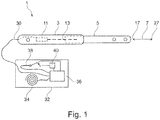
- FIG. 1 a mechatronic implant 1 is shown which represents a typical embodiment.
- the mechatronic implant 1 is designed as an intramedullary nail and comprises a first element 3 and a second element 5.
- the first element 3 is at least partially hollow and partially receives the second element 5, so that the second element 5 out of the first element 3 and into it is slidable along a movement direction 7.
- the mechatronic implant 1 of Fig. 1 It is an adjustable intramedullary nail, which is used for distractions of long bones.
- Typical embodiments of the invention relate to adjustable intramedullary nails as mechatronic implants, further embodiments include devices for scoliosis treatment or other mechatronic implants that can perform movements in the body.
- the mechatronic implant 1 of the Fig. 1 comprises a drive 11, which comprises a spindle as an output 13.
- the output 13 is connected to the second element 5.
- the drive 11 is fixedly connected to the first element 3 or accommodated in a housing or a hollow cylinder of the first element 3.
- the output 13 is moved to move the second element 5 along the direction of movement 7, which runs in the longitudinal direction of the mechatronic implant.
- the drive 11 is configured to move the second element 5 relative to the first element 3 in a first operating direction 17 and in a second, opposite operating direction 27.
- the operating directions 17 and 27 extend along the movement axis 7.
- Typical embodiments include a drive which is designed as an electrical machine.
- Other embodiments include hydraulic drives.
- the mechatronic implant 1 further comprises an energy receiver 32 connected to the drive by a 20 cm long cable 30.
- the energy receiver 32 comprises a housing in which a coil 34 is arranged, which is suitable for receiving energy by inductive energy transmission.
- the housing of the energy receiver 32 may be implanted in a body of a patient, typically subcutaneously. By inductive Energy transfer by utilizing the coil 34, it is possible to supply power to the energy receiver 32.
- the energy receiver 32 has a connection unit 36, to which a switch 38, the coil 34 and a piezo-buzzer 40 are electrically contacted with each other.
- the switch 38 may be embodied in embodiments as a reed contact, which is actuated by extracorporeal means of a magnet.
- the terms "reed contact” and “switch” also include combinations of several reed contacts, for example two reed changeover contacts for polarity reversal.
- the energy receiver 32 includes within its housing the piezo-buzzer 40, which is actuated if the switch 38 is closed and if current flows through the switch 38, for example, upon energizing the coil 34 with electromagnetic energy.
- the interconnection unit is purely hardware-based, so it is software-free. This offers the advantage of a high reliability of a simple construction and, especially for an application in the medical field, also possibly simplified test methods for checking the technical reliability of the mechatronic implant.
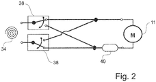
- FIG. 12 is one way of interconnection as may be realized by the interconnect unit and as used in typical embodiments. This will be in connection with the Fig. 1 described parts are not explained again individually, but instead of the same parts reference numbers are used.
- the coil 34 is connected to the switch 38, which is designed for example in the form of two reed changeover contacts. This reversal and thus changing the direction of the drive 11 is possible. For this purpose, both reed changer contacts are operated simultaneously. By actuating a change in direction between the first direction of movement 17 and the second direction of movement 27 is thus possible.
- the switch is provided with a plurality of reed contacts.
- an electronic component can be used to achieve reversal and thus change in direction of the drive.
- a typical embodiment uses only a reed contact, which drives an electronic module connected between the coil and the drive and upon actuation of the Switch reverses the engine and thus changes the direction of rotation.
- a piezo-buzzer 40 connected in series with one of the reed changeover contacts is actuated or energized as a feedback device.
- a piezo-buzzer 40 By operating the piezo-buzzer 40, it is possible in a subcutaneous implantation corresponding also perceive acoustic signals extra-corporeal. Furthermore, it may be possible in embodiments that the patient himself feels the vibration and can give corresponding feedback.
- Embodiments may include a piezo buzzer connected to an electronic component or a piezo buzzer provided with a freewheeling diode to generate a signal only at a particular polarity.
- the different running direction of the electric machine of the drive can be achieved in embodiments in that a voltage intermediate circuit is provided with negative polarity, typically a piezo buzzer or other display device is firmly mounted in the negative-polarity voltage intermediate circuit or in the positive-polarity voltage intermediate circuit.
- a signal of the piezo buzzer can be heard extracorporeally, in particular with a stethoscope.
- the simple construction may result in low or no admission restrictions in the field of medical technology.
- a reed contact can be switched by an extra-corporal brought up magnet.
- the term "reed contact” basically also includes reed changeover contacts, which may be distinguished by the fact that they allow a polarity reversal.
- the reed contact and / or the piezo buzzer may be accommodated on a common electronic board, in particular together with a coil for energy reception. This offers a compact structure.
- the piezo buzzer is activated in both directions of movement, for example with different timing and / or with different pitch and / or with different tone sequence.
- Timing of the drive for example an operation for 2 seconds with interruptions for 1 second in one direction and one operation for 1 second with interruptions of 2 seconds in the other direction.
- timing of the drive for example an operation for 2 seconds with interruptions for 1 second in one direction and one operation for 1 second with interruptions of 2 seconds in the other direction.
Landscapes
- Health & Medical Sciences (AREA)
- Orthopedic Medicine & Surgery (AREA)
- Life Sciences & Earth Sciences (AREA)
- Surgery (AREA)
- Neurology (AREA)
- Heart & Thoracic Surgery (AREA)
- General Health & Medical Sciences (AREA)
- Biomedical Technology (AREA)
- Nuclear Medicine, Radiotherapy & Molecular Imaging (AREA)
- Medical Informatics (AREA)
- Molecular Biology (AREA)
- Animal Behavior & Ethology (AREA)
- Engineering & Computer Science (AREA)
- Public Health (AREA)
- Veterinary Medicine (AREA)
- Physics & Mathematics (AREA)
- Electromagnetism (AREA)
- Prostheses (AREA)
- Surgical Instruments (AREA)
Description
- Die Erfindung betrifft ein mechatronisches Implantat, insbesondere einen Marknagel.
- Aus dem Stand der Technik sind mechatronische Implantate bekannt. Insbesondere sind Implantate bekannt, welche über einen Antrieb verfügen, mit welchem ein erstes Element des Implantats gegenüber einem zweiten Element bewegt werden kann, beispielsweise für die Distraktion eines langen Röhrenknochens.
- Aus der
EP 2 570 092 ist ein System bekannt, bei welchem zur Verlängerung eines langen Röhrenknochens oder zur Wiederherstellung von verloren gegangenem Knochenmaterial, beispielsweise im Nachgang einer Behandlung eines Tumors, ein Marknagel mit einem Antrieb in den Knochen eingebracht wird. Solche Systeme verlangen eine Steuerung, welche schrittweise die Länge des Marknagels neu einstellt, beispielsweise den Marknagel durch Betätigen des Antriebs jeden Tag jeweils um 1 mm verlängert. - Typische Implantate lassen im Normalbetrieb nur eine Bewegungsrichtung zu. Dies kann je nach Anwendungsfall limitierend sein. Komplexere Systeme, welche beispielsweise über eine Steuerungssoftware im Implantat verfügen könnten hier u.U. Abhilfe schaffen, sind jedoch schwieriger zu überwachen und u.U. nicht ausreichend zuverlässig oder benötigen komplizierte Testverfahren zur Zulassung,
-
EP 2 422 731 A1 ist der nächstliegende Stand der Technik und beschreibt ein mechatronisches Implantat gemäß Oberbegriff des Anspruchs 1. - Aufgabe der Erfindung ist es, ein Implantat oder einen Marknagel anzugeben, welche gegenüber dem Stand der Technik verbessert sind, welche insbesondere eine verbesserte Anwendbarkeit oder einen höheren Komfort für Patienten aufweisen bei möglichst zuverlässiger Funktionsweise.
- Die Aufgabe wird mit einem Implantat gemäß Hauptanspruch 1 gelöst.
- Ein Aspekt der Erfindung betrifft ein mechatronisches Implantat zur Verwendung in einem menschlichen Körper, mit einem ersten Element, einem zweiten Element, einem Antrieb, der mit dem ersten Element fixiert verbunden ist, wobei der Antrieb einen Abtrieb umfasst, welcher mit dem zweiten Element verbunden ist, um das zweite Element relativ zu dem ersten Element zu bewegen, einem mit dem Antrieb verbunden, implantierbaren Energieempfänger zum drahtlosen Versorgen des Antriebs mit Energie, und mit einem Schalter, um den Antrieb von einer ersten Betriebsrichtung in eine zweite Betriebsrichtung umzuschalten.
- Typischerweise wird das zweite Element relativ zu dem ersten Element entlang einer Bewegungsrichtung, beispielsweise linear bewegt. Bei weiteren Ausführungsbeispielen wird das zweite Element rotatorisch oder gemischt linear-rotatorisch relativ zu dem ersten Element bewegt. Eine lineare Bewegung kann beispielsweise entlang einer Längsachse eines distraktionsfähigen orthopädischen Implantates wie beispielsweise einem Marknagel erfolgen.
- Der Energieempfänger ist typischerweise zum drahtlosen Versorgen des Antriebs von außerhalb eines Körpers mit Energie eingerichtet. Energie kann bei Ausführungsformen drahtlos beispielsweise über Induktion oder über kapazitive oder mechanische Kopplung übertragen werden.
- Typische Ausführungsformen umfassen eine implantierbare Rückmeldeeinrichtung zum Anzeigen, ob der Antrieb in der ersten Betriebsrichtung oder in der zweiten Betriebsrichtung betrieben wird. Typischerweise erfolgt das Anzeigen drahtlos. Dies bietet den Effekt, dass neben einer drahtlosen Energieübertragung auch eine drahtlose Rückmeldung über die Betriebsrichtung möglich ist. Typischerweise erfolgt das Anzeigen nach außerhalb des Körpers. Typische drahtlose Anzeigemittel oder Rückmeldeeinrichtungen zum drahtlosen Anzeigen umfassen Einrichtungen zum Aussenden von Licht, elektromagnetischen Wellen oder von mechanischen Vibrationen.
- Typische Ausführungsformen umfassen eine Rückmeldeeinrichtung, welche für eine funkwellenlose Übertragung eingerichtet ist. Dies bietet den Effekt, dass ein Rückkanal der Rückmeldeeinrichtung nicht ebenso wie ein Steuerkanal zum Steuern des mechatronischen Implantats auf Funkwellen zurückgreifen muss. Auf diese Weise kann die Betriebssicherheit erhöht werden.
- Typischerweise ist die Rückmeldeeinrichtung bei Ausführungsformen ausgewählt aus: einem akustischen Signalgeber, einem optischen Signalgeber oder einem Vibrations-Signalgeber. Ein akustischer Signalgeber bietet den Effekt, dass er einfach aufgebaut sein kann, ein optischer Signalgeber ist auch bei lauten Umgebungsgeräuschen wahrzunehmen und ein Vibrations-Signalgeber arbeitet unabhängig von Ton oder Licht und kann bei Ausführungsformen auch vom Patienten selbst unmittelbar durch entsprechende subkutane Nerven gespürt werden.
- Bei typischen Ausführungsformen ist die Rückmeldeeinrichtung zusammen mit dem Energieempfänger in einem implantierbaren Gehäuse angeordnet. Typischerweise ist die Rückmeldeeinrichtung zusammen mit dem Energieempfänger und zusammen mit dem Schalter in einem implantierbaren Gehäuse angeordnet. Dies bietet einen kompakten Aufbau.
- Bei Ausführungsformen wird ein von einem Signalgeber der Rückmeldeeinrichtung ausgegebenes Signal moduliert, beispielsweise wird ein akustisches Signal oder optisches Signal moduliert. Solche Modulationen können beispielsweise eine bestimmte Abfolge von zeitlichen Unterbrechungen des Signals umfassen oder unterschiedliche Tonhöhen oder unterschiedliche Lichtstärken. Auf diese Weise können zusätzliche Informationen beispielweise über eine Geschwindigkeit der Bewegung oder über einen Kraftaufwand oder Energieaufwand, welcher für eine Bewegung notwendig ist, übermittelt werden.
- Typischerweise ist die Rückmeldeeinrichtung dazu eingerichtet, eine Information über eine durch den Antrieb bewirkte Bewegungsgeschwindigkeit des zweiten Elements relativ zu dem ersten Element zu übermitteln. Hierfür kann eine Signalmodulation eingesetzt werden, beispielsweise unterschiedliche Tonhöhen, unterschiedliche Lautstärken, unterschiedliche Lichtintensitäten oder Puls-Pause-Verfahren.
- Bei typischen Ausführungsformen ist der Schalter ausgewählt aus: einem Reed-Kontakt, einer Photodiode, einem Kondensator und einem elektromechanischen Druckschalter. Bei Verwendung eines Kondensators kann die Haut Dielektrikum verwendet werden. Photodioden reagieren auf Lichtreize von außen, bspw. von extrakorporal, wohingegen elektromechanische Druckschalter durch mechanische Einwirkung umschaltbar sind.
- Bei typischen Ausführungsformen umfasst der Antrieb eine elektrische Maschine und/oder ein Getriebe. Elektrische Antriebe bieten den Effekt, dass sie besonders kompakt gebaut sein können und sauber sind. Mit Getrieben lässt sich eine besonders große Kraft bei einem kleinen elektrischen Antrieb erreichen.
- Typische Ausführungsformen von mechatronischen Implantaten sind als Marknagel oder als Skoliose-Behandlungseinrichtung ausgebildet. Insbesondere bei Implantaten, welche einer Verschiebung von Knochenteilen relativ zueinander dienen, ist eine Information über die Bewegungsrichtung sinnvoll, da in der Regel nur sehr kleine Bewegungen pro Schritt durchgeführt werden oder durchgeführt werden können, um die Knochen nicht zu überlasten. Bei solchen kleinen Bewegungen ist es nicht auf den ersten Blick ersichtlich, in welche Richtung eine solche Bewegung erfolgt. Bei solchen Anwendungen sind Rückmeldeeinrichtungen zur Information über die Bewegungsrichtung von großem Nutzen.
- Typischerweise der Energieempfänger über ein mindestens 10cm-langes Kabel, bei weiteren Ausführungsformen über ein mindestens 15cm-langes oder über ein mindestens 20cm-langes Kabel mit dem Antrieb verbunden. Auf diese Weise kann eine subkutane Implantierung des Energieempfängers, ggf. zusammen mit der Rückmeldeeinrichtung und/oder dem Schalter in einem Gehäuse subkutan implantiert werden, sodass beispielsweise auch eine optische Rückmeldung durch die Haut möglich ist.
- Weitere Vorteile und Merkmale bevorzugter Ausführungsformen der Erfindung werden nachfolgend anhand der beiliegenden Zeichnungen erläutert, wobei die Figuren zeigen:
- Figur 1
- zeigt in einer schematischen Ansicht eine Ausführungsform der Erfindung; und
- Figur 2
- zeigt eine Ausführungsform eines Details des Ausführungsbeispiels der
Figur 1 in einer weiteren schematischen Ansicht. - In der
Figur 1 ist ein mechatronisches Implantat 1 gezeigt, welches eine typische Ausführungsform darstellt. - Das mechatronische Implantat 1 ist als Marknagel ausgeführt und umfasst ein erstes Element 3 und ein zweites Element 5. Das erste Element 3 ist zumindest teilweise hohl und nimmt das zweite Element 5 teilweise auf, sodass das zweite Element 5 aus dem ersten Element 3 heraus und hinein schiebbar ist entlang einer Bewegungsrichtung 7. Bei dem mechatronischen Implantat 1 der
Fig. 1 handelt es sich um einen verstellbaren Marknagel, welcher für Distraktionen von langen Röhrenknochen einsetzbar ist. - Typische Ausführungsformen der Erfindung betreffen verstellbare Marknägel als mechatronische Implantate, weitere Ausführungsformen umfassen Vorrichtungen zur Skoliose-Behandlung oder andere mechatronische Implantate, welche Bewegungen im Körper ausführen können.
- Das mechatronische Implantat 1 der
Fig. 1 umfasst einen Antrieb 11, welcher eine Spindel als Abtrieb 13 umfasst. Der Abtrieb 13 ist mit dem zweiten Element 5 verbunden. Der Antrieb 11 ist fixiert mit dem ersten Element 3 verbunden bzw. in einem Gehäuse oder einem Hohlzylinder des ersten Elementes 3 aufgenommen. - Durch Betätigen des Antriebs 11 erfolgt eine Bewegung des Abtriebs 13, um das zweite Element 5 entlang der Bewegungsrichtung 7, welche in Längsrichtung des mechatronischen Implantats verläuft, zu bewegen.
- Der Antrieb 11 ist dazu eingerichtet, das zweite Element 5 relativ zu dem ersten Element 3 in eine erste Betriebsrichtung 17 und in eine zweite, entgegengesetzte Betriebsrichtung 27 zu bewegen. Die Betriebsrichtungen 17 und 27 verlaufen entlang der Bewegungsachse 7.
- Typische Ausführungsformen umfassen einen Antrieb, welcher als elektrische Maschine ausgebildet ist. Weitere Ausführungsformen umfassen hydraulische Antriebe.
- Das mechatronische Implantat 1 umfasst weiterhin ein durch ein 20cm langes Kabel 30 mit dem Antrieb verbundenen Energieempfänger 32. Der Energieempfänger 32 umfasst ein Gehäuse, in welchem eine Spule 34 angeordnet ist, welche dazu geeignet ist, durch induktive Energieübertragung Energie zu empfangen.
- Das Gehäuse des Energieempfängers 32 kann in einen Körper eines Patienten implantiert werden, typischerweise subkutan. Durch induktive Energieübertragung unter Ausnutzung der Spule 34 ist es möglich, dem Energieempfänger 32 Energie zuzuführen.
- Weiterhin verfügt der Energieempfänger 32 über eine Verschaltungseinheit 36, an welcher ein Schalter 38, die Spule 34 und ein Piezo-Summer 40 elektrisch miteinander kontaktiert werden.
- Der Schalter 38 kann bei Ausführungsformen als Reed-Kontakt ausgeführt sein, welcher von extra-korporal mittels eines Magneten betätigbar ist. Unter die Begriffe "Reed-Kontakt" und "Schalter" fallen dabei auch Kombinationen mehrerer Reed-Kontakte, beispielsweise zwei Reed-Wechsler-Kontakte zur Umpolung. Durch Betätigung des Schalters 38 kann durch die entsprechende Verschaltung in der Verschaltungseinheit 36 bewirkt werden, dass die Richtung der Bewegung entlang der Bewegungsachse 7 geändert wird, beispielsweise von der ersten Bewegungsrichtung 17 in die zweite Bewegungsrichtung 27 bei Schließen des Schalters und von der zweiten Bewegungsrichtung 27 zu der ersten Bewegungsrichtung 17 bei einem Öffnen des Schalters 38.
- Bei typischen Ausführungsformen umfasst der Energieempfänger 32 innerhalb seines Gehäuses den Piezo-Summer 40, welcher betätigt wird, falls der Schalter 38 geschlossen ist und falls Strom durch den Schalter 38 fließt, beispielsweise bei Beaufschlagung der Spule 34 mit elektromagnetischer Energie.
- Typischerweise ist die Verschaltungseinheit rein Hardware-mäßig aufgebaut, ist also Software-los. Dies bietet den Vorteil einer hohen Zuverlässigkeit eines einfachen Aufbaus und speziell bei einer Anwendung im medizinischen Bereich auch eventuell vereinfachte Prüfverfahren zur Überprüfung der technischen Zuverlässigkeit des mechatronischen Implantats.
- Weitere Ausführungsformen umfassen eine zentrale Steuereinheit der Verschaltungseinheit, wobei die zentrale Steuereinheit Software-basiert arbeiten kann. Dies bietet den Vorteil, dass Neuprogrammierungen vorgenommen werden können.
- Bei weiteren Ausführungsformen sind andere Schalter als der Reed-Kontakt des Schalters 38 oder andere Rückmeldeeinrichtungen als der Piezo-Summer 40 des Ausführungsbeispiels der
Fig.1 vorgesehen. Weitere Beispiele sind an anderer Stelle in dieser Anmeldung genannt. Grundsätzlich ist die Darstellung derFig. 1 insbesondere bezüglich des Schalters 38 sehr schematisch. Eine genauere Darstellung einer Ausführungsform wird nachfolgend im Zusammenhang mit derFig. 2 beschrieben. - In der
Fig. 2 ist eine Möglichkeit der Verschaltung, wie sie durch die Verschaltungseinheit realisiert werden kann und wie sie bei typischen Ausführungsformen verwendet wird, gezeigt. Dabei werden die bereits im Zusammenhang mit derFig. 1 beschriebenen Teile nicht nochmals einzeln erläutert, vielmehr werden für gleiche Teile Bezugszeichen verwendet. - Die Spule 34 ist mit dem Schalter 38 verbunden, welcher beispielsweise in Form von zwei Reed-Wechsler-Kontakten ausgeführt ist. Damit ist eine Umpolung und damit Laufrichtungsänderung des Antriebs 11 möglich. Hierzu werden beide Reed-Wechsler-Kontakte gleichzeitig betätigt. Durch Betätigung ist somit eine Richtungsänderung zwischen der ersten Bewegungsrichtung 17 und der zweiten Bewegungsrichtung 27 möglich.
- Bei Ausführungsformen ist der Schalter mit einer Mehrzahl von Reed-Kontakten versehen. Bei weiteren Ausführungsformen kann eine elektronische Komponente verwendet werden, um eine Umpolung und damit Laufrichtungsänderung des Antriebs zu erreichen.. Eine typische Ausführungsform verwendet lediglich einen Reed-Kontakt, welcher einen Elektronik-Baustein ansteuert, der zwischen Spule und Antrieb geschaltet ist und bei Betätigung des Schalters den Motor umpolt und somit dessen Drehrichtung ändert.
- Je nach Betätigung der Reed-Wechsler-Kontakte des Schalters 38 wird ein in Serie mit einem der Reed-Wechsler-Kontakte geschalteter Piezo-Summer 40 als Rückmeldeeinrichtung betätigt oder bestromt. Durch Betätigung des Piezo-Summers 40 ist es möglich bei einer subkutanen Implantierung entsprechende akustische Signale auch extra-korporal wahrzunehmen. Weiterhin kann es bei Ausführungsformen möglich sein, dass der Patient selbst die Vibration spürt und entsprechend Rückmeldung geben kann. Ausführungsformen können einen an eine elektronische Komponente angeschlossenen Piezo-Summer umfassen oder einen Piezo-Summer, welcher mit einer Freilaufdiode versehen ist, um nur bei einer bestimmten Polung ein Signal zu erzeugen.
- Die unterschiedliche Laufrichtung der elektrischen Maschine des Antriebs kann bei Ausführungsformen dadurch erreicht werden, dass ein Spannungszwischenkreis mit negativer Polung geschaffen wird, wobei typischerweise ein Piezo-Summer oder eine andere Anzeigeneinrichtung in den negativ gepolten Spannungszwischenkreis oder in den positiv gepolten Spannungszwischenkreis fest angebracht wird. Bei einer Polung mit zwischengeschaltetem Piezo-Summer kann ein Signal des Piezo-Summers extra-korporal gehört, insbesondere mit einem Stethoskop, werden.
- Durch den einfachen Aufbau können sich niedrige oder keine Zulassungsbeschränkungen in dem Bereich der Medizintechnik ergeben.
- Typischerweise kann ein Reed-Kontakt durch einen extra-korporal herangeführten Magneten geschaltet werden. Von dem Begriff "Reed-Kontakt" sind grundsätzlich auch Reed-Wechsler-Kontakte umfasst, welche sich dadurch auszeichnen können, dass sie eine Umpolung ermöglichen. Bei typischen Ausführungsformen können der Reed-Kontakt und/oder der Piezo-Summer auf einer gemeinsamen Elektronikplatine, insbesondere zusammen mit einer Spule für einen Energieempfang, aufgenommen sein. Dies bietet einen kompakten Aufbau.
- Bei Ausführungsformen wird der Piezo-Summer bei beiden Bewegungsrichtungen aktiviert, beispielweise mit unterschiedlicher Taktung und/oder mit unterschiedlicher Tonhöhe und/oder mit unterschiedlicher Tonabfolge.
- Eine Möglichkeit stellt eine Taktung des Antriebs dar, beispielsweise ein Betrieb für 2 Sekunden mit Unterbrechungen für 1 Sekunde in die eine Richtung und einen Betrieb jeweils für 1 Sekunde mit Unterbrechungen von 2 Sekunden in die andere Richtung. Auf diese Weise können unterschiedliche Bewegungsrichtungen insbesondere mit dem Stethoskop von außen detektiert werden.
- In der vorstehenden Beschreibung wurden typische Ausführungsbeispiele anhand von Figuren erläutert, die Erfindung ist jedoch nicht auf diese Ausführungsbeispiele beschränkt; vielmehr wird der Umfang der Erfindung durch die Ansprüche bestimmt.
Claims (8)
- Mechatronisches Implantat (1) zur Verwendung in einem menschlichen Körper, mit- einem ersten Element (3),- einem zweiten Element (5),- einem Antrieb (11), der mit dem ersten Element (3) fixiert verbunden ist, wobei der Antrieb (11) einen Abtrieb (13) umfasst, welcher mit dem zweiten Element (5) verbunden ist, um das zweite Element (5) relativ zu dem ersten Element (3) zu bewegen,- einem mit dem Antrieb (11) verbundenen, implantierbaren Energieempfänger (32) zum drahtlosen Versorgen des Antriebs (11) mit Energie,- einem Schalter (38), um den Antrieb (11) von einer ersten Betriebsrichtung (17) in eine zweite Betriebsrichtung (27) umzuschalten, dadurch gekennzeichnet, dass das Implantat (1)- mit einer implantierbaren Rückmeldeeinrichtung zum Anzeigen, ob der Antrieb (11) in der ersten Betriebsrichtung (17) oder in der zweiten Betriebsrichtung (27) betrieben wird,- wobei die Rückmeldeeinrichtung für eine funkwellenlose Übertragung eingerichtet ist.
- Mechatronisches Implantat (1) nach Anspruch 1, wobei die Rückmeldeeinrichtung ausgewählt ist aus: einem akustischen Signalgeber, einem optischen Signalgeber oder einem Vibrationssignalgeber.
- Mechatronisches Implantat (1) nach einem der vorhergehenden Ansprüche, wobei die Rückmeldeeinrichtung zusammen mit dem Energieempfänger (32) in einem implantierbaren Gehäuse angeordnet ist.
- Mechatronisches Implantat (1) nach einem der vorhergehenden Ansprüche, wobei die Rückmeldeeinrichtung dazu eingerichtet ist, eine Information über eine durch den Antrieb (11) bewirkte Bewegungsgeschwindigkeit des zweiten Elementes (5) relativ zu dem ersten Element (3) zu übermitteln
- Mechatronisches Implantat (1) nach einem der vorhergehenden Ansprüche, wobei der Schalter (38) ausgewählt ist aus: einem Reed-Kontakt, einer Photodiode, einem Kondensator und einem elektromechanischen Druckschalter.
- Mechatronisches Implantat (1) nach einem der vorhergehenden Ansprüche, wobei der Antrieb (11) eine elektrische Maschine und/oder ein Getriebe umfasst.
- Mechatronisches Implantat (1) nach einem der vorhergehenden Ansprüche, welches als Marknagel oder als Skoliosebehandlungseinrichtung ausgebildet ist.
- Mechatronisches Implantat (1) nach einem der vorhergehenden Ansprüche, wobei der Energieempfänger (32) über ein mindestens 20 cm langes Kabel (30) mit dem Antrieb (11) verbunden ist.
Applications Claiming Priority (1)
| Application Number | Priority Date | Filing Date | Title |
|---|---|---|---|
| DE102015109624.2A DE102015109624A1 (de) | 2015-06-16 | 2015-06-16 | Mechatronisches Implantat |
Publications (2)
| Publication Number | Publication Date |
|---|---|
| EP3106111A1 EP3106111A1 (de) | 2016-12-21 |
| EP3106111B1 true EP3106111B1 (de) | 2018-04-18 |
Family
ID=56235591
Family Applications (1)
| Application Number | Title | Priority Date | Filing Date |
|---|---|---|---|
| EP16174443.8A Active EP3106111B1 (de) | 2015-06-16 | 2016-06-14 | Mechatronisches implantat |
Country Status (3)
| Country | Link |
|---|---|
| US (1) | US9943345B2 (de) |
| EP (1) | EP3106111B1 (de) |
| DE (1) | DE102015109624A1 (de) |
Families Citing this family (8)
| Publication number | Priority date | Publication date | Assignee | Title |
|---|---|---|---|---|
| JP2012507340A (ja) * | 2008-10-31 | 2012-03-29 | ミルックス・ホールディング・エスエイ | エネルギーの無線伝送を使用して骨調節を操作するためのデバイスおよび方法 |
| CN107106209B (zh) * | 2014-10-23 | 2020-07-14 | 诺威适骨科专科公司 | 骨骼生长装置和用于该骨骼生长装置的外部遥控 |
| PL3491998T3 (pl) * | 2017-11-30 | 2021-11-15 | Endotact | Wszczepialne urządzenie do dystrakcji |
| DE102019122354A1 (de) * | 2019-08-20 | 2021-02-25 | Orthofix Srl | Marknagel für eine Distraktion eines Röhrenknochens |
| WO2022055678A1 (en) * | 2020-09-08 | 2022-03-17 | Nuvasive Specialized Orthopedics, Inc. | Remote control module for adjustable implants |
| EP4297674A1 (de) * | 2021-02-23 | 2024-01-03 | NuVasive Specialized Orthopedics, Inc. | Einstellbares implantat, system und verfahren |
| WO2022204096A1 (en) * | 2021-03-24 | 2022-09-29 | Smith & Nephew, Inc. | Implantable motorized bone adjustment devices |
| US12484936B1 (en) * | 2024-07-17 | 2025-12-02 | David Skaggs | Systems and methods for treating spinal conditions |
Family Cites Families (36)
| Publication number | Priority date | Publication date | Assignee | Title |
|---|---|---|---|---|
| WO1987007134A1 (en) * | 1986-05-30 | 1987-12-03 | John Bumpus | Distraction rods |
| US5626579A (en) * | 1993-02-12 | 1997-05-06 | The Cleveland Clinic Foundation | Bone transport and lengthening system |
| US5350379A (en) * | 1993-02-18 | 1994-09-27 | Genesis Orthopedics | Bone and tissue lengthening device |
| FR2730406B1 (fr) | 1995-02-13 | 1997-08-14 | Medinov Sa | Dispositif d'allongement perfectionne d'os longs |
| US5626581A (en) * | 1995-11-27 | 1997-05-06 | Volunteers For Medical Engineering | Implantable bone lengthening apparatus |
| DE19717357A1 (de) * | 1997-04-24 | 1999-02-11 | Augustin Prof Dr Betz | Distraktionsvorrichtung |
| US6927693B2 (en) * | 2001-10-26 | 2005-08-09 | Koninklijke Philips Electronics, N.V. | Portable signal activator assembly |
| US20040147928A1 (en) * | 2002-10-30 | 2004-07-29 | Landry Michael E. | Spinal stabilization system using flexible members |
| WO2004107376A1 (en) * | 2003-05-30 | 2004-12-09 | Koninklijke Philips Electronics N.V. | Magnetic toggle switch |
| US7955357B2 (en) * | 2004-07-02 | 2011-06-07 | Ellipse Technologies, Inc. | Expandable rod system to treat scoliosis and method of using the same |
| US20060079897A1 (en) * | 2004-09-29 | 2006-04-13 | Harrison Michael R | Apparatus and methods for magnetic alteration of anatomical features |
| US8915915B2 (en) * | 2004-09-29 | 2014-12-23 | The Regents Of The University Of California | Apparatus and methods for magnetic alteration of anatomical features |
| US7927357B2 (en) * | 2005-02-02 | 2011-04-19 | Depuy Spine, Inc. | Adjustable length implant |
| US7846188B2 (en) * | 2005-04-12 | 2010-12-07 | Moskowitz Nathan C | Bi-directional fixating transvertebral body screws, zero-profile horizontal intervertebral miniplates, total intervertebral body fusion devices, and posterior motion-calibrating interarticulating joint stapling device for spinal fusion |
| US7753915B1 (en) * | 2007-06-14 | 2010-07-13 | August Eksler | Bi-directional bone length adjustment system |
| US20090112263A1 (en) * | 2007-10-30 | 2009-04-30 | Scott Pool | Skeletal manipulation system |
| US8092499B1 (en) * | 2008-01-11 | 2012-01-10 | Roth Herbert J | Skeletal flexible/rigid rod for treating skeletal curvature |
| DE102008036689A1 (de) * | 2008-08-06 | 2010-02-11 | Feld, Christoph M. | Distraktionsvorrichtung |
| JP2012507340A (ja) * | 2008-10-31 | 2012-03-29 | ミルックス・ホールディング・エスエイ | エネルギーの無線伝送を使用して骨調節を操作するためのデバイスおよび方法 |
| US20100114103A1 (en) * | 2008-11-06 | 2010-05-06 | The Regents Of The University Of California | Apparatus and methods for alteration of anatomical features |
| US8382756B2 (en) * | 2008-11-10 | 2013-02-26 | Ellipse Technologies, Inc. | External adjustment device for distraction device |
| GB0915382D0 (en) * | 2009-09-03 | 2009-10-07 | Dalmatic As | Expansion devices |
| FR2949662B1 (fr) * | 2009-09-09 | 2011-09-30 | Arnaud Soubeiran | Dispositif intra corporel pour le deplacement de tissus |
| US8585740B1 (en) * | 2010-01-12 | 2013-11-19 | AMB Surgical, LLC | Automated growing rod device |
| US8876870B2 (en) * | 2010-04-27 | 2014-11-04 | Adnan Iqbal Qureshi | Intraspinal device deployed through percutaneous approach into subarachnoid or intradural space of vertebral canal to protect spinal cord from external compression |
| US20120035656A1 (en) * | 2010-08-09 | 2012-02-09 | Ellipse Technologies, Inc. | External maintenance feature for magnetic implant |
| DE102010047738A1 (de) * | 2010-08-26 | 2012-03-01 | Wittenstein Ag | Aktuator zur Skoliosekorrektur |
| US8961567B2 (en) * | 2010-11-22 | 2015-02-24 | DePuy Synthes Products, LLC | Non-fusion scoliosis expandable spinal rod |
| US9333009B2 (en) * | 2011-06-03 | 2016-05-10 | K2M, Inc. | Spinal correction system actuators |
| DE102011053638A1 (de) | 2011-09-15 | 2013-03-21 | Wittenstein Ag | Marknagel |
| US10016226B2 (en) * | 2011-12-12 | 2018-07-10 | Children's Hospital Medical Center Of Akron | Noninvasive device for adjusting fastener |
| US9427261B2 (en) * | 2012-06-13 | 2016-08-30 | Warsaw Orthopedic, Inc. | Spinal correction system and method |
| US9179938B2 (en) * | 2013-03-08 | 2015-11-10 | Ellipse Technologies, Inc. | Distraction devices and method of assembling the same |
| US20140358150A1 (en) * | 2013-05-29 | 2014-12-04 | Children's National Medical Center | Surgical distraction device with external activation |
| CA2917676A1 (en) * | 2015-01-13 | 2016-07-13 | Stryker European Holdings I, Llc | Growing rods and methods of use |
| US9949759B2 (en) * | 2015-10-05 | 2018-04-24 | Globus Medical, Inc. | Growing rod for treating spinal deformities and method for using same |
-
2015
- 2015-06-16 DE DE102015109624.2A patent/DE102015109624A1/de not_active Withdrawn
-
2016
- 2016-06-14 EP EP16174443.8A patent/EP3106111B1/de active Active
- 2016-06-16 US US15/183,958 patent/US9943345B2/en active Active
Non-Patent Citations (1)
| Title |
|---|
| None * |
Also Published As
| Publication number | Publication date |
|---|---|
| DE102015109624A1 (de) | 2016-12-22 |
| US9943345B2 (en) | 2018-04-17 |
| EP3106111A1 (de) | 2016-12-21 |
| US20160367297A1 (en) | 2016-12-22 |
Similar Documents
| Publication | Publication Date | Title |
|---|---|---|
| EP3106111B1 (de) | Mechatronisches implantat | |
| DE10351199B3 (de) | Steuereinrichtung zur Steuerung elektromedizinischer Geräte | |
| EP2422731B1 (de) | Aktuator zur Skoliosekorrektur | |
| EP2130566B1 (de) | Langgestrecktes Implantat mit externer Energieeinkopplung | |
| DE69600837T2 (de) | Vorrichtung zum verlängern von länglichen knochen | |
| DE19908851A1 (de) | Marknagel zur Knochendistraktion | |
| DE10055519A1 (de) | Distraktionsvorrichtung | |
| DE202010009899U1 (de) | Stoßwellenapparatur zur Erzeugung von mechanischen Stoßwellen und Stoßwellengerät | |
| EP1707109A1 (de) | Datenübertragungssystem in Verbindung mit einem Implantat | |
| WO2017055465A1 (de) | Magnetische stimulationsvorrichtung | |
| DE69608247T2 (de) | Transkutane elektrische verbindungseinheit für ein medizinisches implantat | |
| DE102007036359A1 (de) | Implantatvorrichtung zur Gewebe- und/oder Knochendistraktion sowie Verfahren zum Betreiben einer solchen | |
| DE102005028215A1 (de) | Vorrichtung für die medizinische Versorgung | |
| WO2005094669A1 (de) | System und in ein gewebe von lebewesen implantierbare vorrichtung zur erfassung und beeinflussung von elektrischer bio-aktivität | |
| EP2153869B1 (de) | Befeldungsgerät zur Befeldung von Körperteilen von Lebewesen mit elektromagnetischen Wellen | |
| DE102013111354A1 (de) | Fixateur interne | |
| DE102004009135B3 (de) | Vorrichtung zur von Hand fernsteuerbaren Navigation einer in einen menschlichen Körper einführbaren Sonde | |
| WO2017190955A1 (de) | Endoskopiesystem, endoskop und kamerakopf | |
| EP2446921A1 (de) | Auswahlschaltung für eine Elektrodenanordnung sowie Verfahren zum Betrieb und zum Herstellen einer Elektrodenanordnung | |
| WO2005110198A1 (de) | Vorrichtung zur änderung der wirkungsrichtung eines instrumentes | |
| EP0885628A2 (de) | Elektronisches Bioresonanzgerät | |
| DE102019218285A1 (de) | Kopfspulenanordnung mit automatisch positionierbarer Sendespuleneinheit | |
| EP4140419B1 (de) | Chirurgisches ultraschallgerät und handstück dafür | |
| EP3871732A1 (de) | Anordnung zum übertragen einer antriebskraft für einen antriebsstrang einer vorrichtung zum lokalen aufstechen einer menschlichen oder einer tierischen haut, antriebsstrang und hautstechvorrichtung | |
| AT504039A1 (de) | Implantat zur befestigung von bändern oder sehnen |
Legal Events
| Date | Code | Title | Description |
|---|---|---|---|
| PUAI | Public reference made under article 153(3) epc to a published international application that has entered the european phase |
Free format text: ORIGINAL CODE: 0009012 |
|
| AK | Designated contracting states |
Kind code of ref document: A1 Designated state(s): AL AT BE BG CH CY CZ DE DK EE ES FI FR GB GR HR HU IE IS IT LI LT LU LV MC MK MT NL NO PL PT RO RS SE SI SK SM TR |
|
| AX | Request for extension of the european patent |
Extension state: BA ME |
|
| 17P | Request for examination filed |
Effective date: 20170609 |
|
| RBV | Designated contracting states (corrected) |
Designated state(s): AL AT BE BG CH CY CZ DE DK EE ES FI FR GB GR HR HU IE IS IT LI LT LU LV MC MK MT NL NO PL PT RO RS SE SI SK SM TR |
|
| GRAP | Despatch of communication of intention to grant a patent |
Free format text: ORIGINAL CODE: EPIDOSNIGR1 |
|
| RIC1 | Information provided on ipc code assigned before grant |
Ipc: A61B 17/72 20060101AFI20170926BHEP Ipc: A61B 17/68 20060101ALI20170926BHEP Ipc: A61B 17/70 20060101ALI20170926BHEP |
|
| INTG | Intention to grant announced |
Effective date: 20171024 |
|
| GRAS | Grant fee paid |
Free format text: ORIGINAL CODE: EPIDOSNIGR3 |
|
| GRAA | (expected) grant |
Free format text: ORIGINAL CODE: 0009210 |
|
| AK | Designated contracting states |
Kind code of ref document: B1 Designated state(s): AL AT BE BG CH CY CZ DE DK EE ES FI FR GB GR HR HU IE IS IT LI LT LU LV MC MK MT NL NO PL PT RO RS SE SI SK SM TR |
|
| REG | Reference to a national code |
Ref country code: GB Ref legal event code: FG4D Free format text: NOT ENGLISH |
|
| REG | Reference to a national code |
Ref country code: CH Ref legal event code: EP |
|
| REG | Reference to a national code |
Ref country code: AT Ref legal event code: REF Ref document number: 989585 Country of ref document: AT Kind code of ref document: T Effective date: 20180515 |
|
| REG | Reference to a national code |
Ref country code: IE Ref legal event code: FG4D Free format text: LANGUAGE OF EP DOCUMENT: GERMAN |
|
| REG | Reference to a national code |
Ref country code: DE Ref legal event code: R096 Ref document number: 502016000897 Country of ref document: DE |
|
| REG | Reference to a national code |
Ref country code: FR Ref legal event code: PLFP Year of fee payment: 3 |
|
| REG | Reference to a national code |
Ref country code: NL Ref legal event code: MP Effective date: 20180418 |
|
| REG | Reference to a national code |
Ref country code: LT Ref legal event code: MG4D |
|
| PG25 | Lapsed in a contracting state [announced via postgrant information from national office to epo] |
Ref country code: NL Free format text: LAPSE BECAUSE OF FAILURE TO SUBMIT A TRANSLATION OF THE DESCRIPTION OR TO PAY THE FEE WITHIN THE PRESCRIBED TIME-LIMIT Effective date: 20180418 |
|
| PG25 | Lapsed in a contracting state [announced via postgrant information from national office to epo] |
Ref country code: AL Free format text: LAPSE BECAUSE OF FAILURE TO SUBMIT A TRANSLATION OF THE DESCRIPTION OR TO PAY THE FEE WITHIN THE PRESCRIBED TIME-LIMIT Effective date: 20180418 Ref country code: ES Free format text: LAPSE BECAUSE OF FAILURE TO SUBMIT A TRANSLATION OF THE DESCRIPTION OR TO PAY THE FEE WITHIN THE PRESCRIBED TIME-LIMIT Effective date: 20180418 Ref country code: FI Free format text: LAPSE BECAUSE OF FAILURE TO SUBMIT A TRANSLATION OF THE DESCRIPTION OR TO PAY THE FEE WITHIN THE PRESCRIBED TIME-LIMIT Effective date: 20180418 Ref country code: PL Free format text: LAPSE BECAUSE OF FAILURE TO SUBMIT A TRANSLATION OF THE DESCRIPTION OR TO PAY THE FEE WITHIN THE PRESCRIBED TIME-LIMIT Effective date: 20180418 Ref country code: LT Free format text: LAPSE BECAUSE OF FAILURE TO SUBMIT A TRANSLATION OF THE DESCRIPTION OR TO PAY THE FEE WITHIN THE PRESCRIBED TIME-LIMIT Effective date: 20180418 Ref country code: BG Free format text: LAPSE BECAUSE OF FAILURE TO SUBMIT A TRANSLATION OF THE DESCRIPTION OR TO PAY THE FEE WITHIN THE PRESCRIBED TIME-LIMIT Effective date: 20180718 Ref country code: SE Free format text: LAPSE BECAUSE OF FAILURE TO SUBMIT A TRANSLATION OF THE DESCRIPTION OR TO PAY THE FEE WITHIN THE PRESCRIBED TIME-LIMIT Effective date: 20180418 Ref country code: NO Free format text: LAPSE BECAUSE OF FAILURE TO SUBMIT A TRANSLATION OF THE DESCRIPTION OR TO PAY THE FEE WITHIN THE PRESCRIBED TIME-LIMIT Effective date: 20180718 |
|
| PG25 | Lapsed in a contracting state [announced via postgrant information from national office to epo] |
Ref country code: GR Free format text: LAPSE BECAUSE OF FAILURE TO SUBMIT A TRANSLATION OF THE DESCRIPTION OR TO PAY THE FEE WITHIN THE PRESCRIBED TIME-LIMIT Effective date: 20180719 Ref country code: HR Free format text: LAPSE BECAUSE OF FAILURE TO SUBMIT A TRANSLATION OF THE DESCRIPTION OR TO PAY THE FEE WITHIN THE PRESCRIBED TIME-LIMIT Effective date: 20180418 Ref country code: RS Free format text: LAPSE BECAUSE OF FAILURE TO SUBMIT A TRANSLATION OF THE DESCRIPTION OR TO PAY THE FEE WITHIN THE PRESCRIBED TIME-LIMIT Effective date: 20180418 Ref country code: LV Free format text: LAPSE BECAUSE OF FAILURE TO SUBMIT A TRANSLATION OF THE DESCRIPTION OR TO PAY THE FEE WITHIN THE PRESCRIBED TIME-LIMIT Effective date: 20180418 |
|
| PG25 | Lapsed in a contracting state [announced via postgrant information from national office to epo] |
Ref country code: PT Free format text: LAPSE BECAUSE OF FAILURE TO SUBMIT A TRANSLATION OF THE DESCRIPTION OR TO PAY THE FEE WITHIN THE PRESCRIBED TIME-LIMIT Effective date: 20180820 |
|
| REG | Reference to a national code |
Ref country code: DE Ref legal event code: R097 Ref document number: 502016000897 Country of ref document: DE |
|
| PG25 | Lapsed in a contracting state [announced via postgrant information from national office to epo] |
Ref country code: CZ Free format text: LAPSE BECAUSE OF FAILURE TO SUBMIT A TRANSLATION OF THE DESCRIPTION OR TO PAY THE FEE WITHIN THE PRESCRIBED TIME-LIMIT Effective date: 20180418 Ref country code: SK Free format text: LAPSE BECAUSE OF FAILURE TO SUBMIT A TRANSLATION OF THE DESCRIPTION OR TO PAY THE FEE WITHIN THE PRESCRIBED TIME-LIMIT Effective date: 20180418 Ref country code: RO Free format text: LAPSE BECAUSE OF FAILURE TO SUBMIT A TRANSLATION OF THE DESCRIPTION OR TO PAY THE FEE WITHIN THE PRESCRIBED TIME-LIMIT Effective date: 20180418 Ref country code: DK Free format text: LAPSE BECAUSE OF FAILURE TO SUBMIT A TRANSLATION OF THE DESCRIPTION OR TO PAY THE FEE WITHIN THE PRESCRIBED TIME-LIMIT Effective date: 20180418 Ref country code: EE Free format text: LAPSE BECAUSE OF FAILURE TO SUBMIT A TRANSLATION OF THE DESCRIPTION OR TO PAY THE FEE WITHIN THE PRESCRIBED TIME-LIMIT Effective date: 20180418 |
|
| PLBE | No opposition filed within time limit |
Free format text: ORIGINAL CODE: 0009261 |
|
| STAA | Information on the status of an ep patent application or granted ep patent |
Free format text: STATUS: NO OPPOSITION FILED WITHIN TIME LIMIT |
|
| PG25 | Lapsed in a contracting state [announced via postgrant information from national office to epo] |
Ref country code: SM Free format text: LAPSE BECAUSE OF FAILURE TO SUBMIT A TRANSLATION OF THE DESCRIPTION OR TO PAY THE FEE WITHIN THE PRESCRIBED TIME-LIMIT Effective date: 20180418 |
|
| REG | Reference to a national code |
Ref country code: BE Ref legal event code: MM Effective date: 20180630 |
|
| REG | Reference to a national code |
Ref country code: IE Ref legal event code: MM4A |
|
| 26N | No opposition filed |
Effective date: 20190121 |
|
| PG25 | Lapsed in a contracting state [announced via postgrant information from national office to epo] |
Ref country code: MC Free format text: LAPSE BECAUSE OF FAILURE TO SUBMIT A TRANSLATION OF THE DESCRIPTION OR TO PAY THE FEE WITHIN THE PRESCRIBED TIME-LIMIT Effective date: 20180418 Ref country code: LU Free format text: LAPSE BECAUSE OF NON-PAYMENT OF DUE FEES Effective date: 20180614 |
|
| PG25 | Lapsed in a contracting state [announced via postgrant information from national office to epo] |
Ref country code: IE Free format text: LAPSE BECAUSE OF NON-PAYMENT OF DUE FEES Effective date: 20180614 |
|
| PG25 | Lapsed in a contracting state [announced via postgrant information from national office to epo] |
Ref country code: SI Free format text: LAPSE BECAUSE OF FAILURE TO SUBMIT A TRANSLATION OF THE DESCRIPTION OR TO PAY THE FEE WITHIN THE PRESCRIBED TIME-LIMIT Effective date: 20180418 Ref country code: BE Free format text: LAPSE BECAUSE OF NON-PAYMENT OF DUE FEES Effective date: 20180630 |
|
| PG25 | Lapsed in a contracting state [announced via postgrant information from national office to epo] |
Ref country code: MT Free format text: LAPSE BECAUSE OF FAILURE TO SUBMIT A TRANSLATION OF THE DESCRIPTION OR TO PAY THE FEE WITHIN THE PRESCRIBED TIME-LIMIT Effective date: 20180418 |
|
| PG25 | Lapsed in a contracting state [announced via postgrant information from national office to epo] |
Ref country code: TR Free format text: LAPSE BECAUSE OF FAILURE TO SUBMIT A TRANSLATION OF THE DESCRIPTION OR TO PAY THE FEE WITHIN THE PRESCRIBED TIME-LIMIT Effective date: 20180418 |
|
| PG25 | Lapsed in a contracting state [announced via postgrant information from national office to epo] |
Ref country code: HU Free format text: LAPSE BECAUSE OF FAILURE TO SUBMIT A TRANSLATION OF THE DESCRIPTION OR TO PAY THE FEE WITHIN THE PRESCRIBED TIME-LIMIT; INVALID AB INITIO Effective date: 20160614 Ref country code: CY Free format text: LAPSE BECAUSE OF FAILURE TO SUBMIT A TRANSLATION OF THE DESCRIPTION OR TO PAY THE FEE WITHIN THE PRESCRIBED TIME-LIMIT Effective date: 20180418 Ref country code: MK Free format text: LAPSE BECAUSE OF NON-PAYMENT OF DUE FEES Effective date: 20180418 |
|
| PG25 | Lapsed in a contracting state [announced via postgrant information from national office to epo] |
Ref country code: IS Free format text: LAPSE BECAUSE OF FAILURE TO SUBMIT A TRANSLATION OF THE DESCRIPTION OR TO PAY THE FEE WITHIN THE PRESCRIBED TIME-LIMIT Effective date: 20180818 |
|
| REG | Reference to a national code |
Ref country code: DE Ref legal event code: R082 Ref document number: 502016000897 Country of ref document: DE Representative=s name: ZIMMERMANN & PARTNER PATENTANWAELTE MBB, DE Ref country code: DE Ref legal event code: R081 Ref document number: 502016000897 Country of ref document: DE Owner name: ORTHOFIX SRL, IT Free format text: FORMER OWNER: WITTENSTEIN SE, 97999 IGERSHEIM, DE |
|
| REG | Reference to a national code |
Ref country code: CH Ref legal event code: PUE Owner name: ORTHOFIX S.R.L., IT Free format text: FORMER OWNER: WITTENSTEIN SE, DE |
|
| REG | Reference to a national code |
Ref country code: GB Ref legal event code: 732E Free format text: REGISTERED BETWEEN 20210520 AND 20210526 |
|
| REG | Reference to a national code |
Ref country code: AT Ref legal event code: MM01 Ref document number: 989585 Country of ref document: AT Kind code of ref document: T Effective date: 20210614 |
|
| PG25 | Lapsed in a contracting state [announced via postgrant information from national office to epo] |
Ref country code: AT Free format text: LAPSE BECAUSE OF NON-PAYMENT OF DUE FEES Effective date: 20210614 |
|
| P01 | Opt-out of the competence of the unified patent court (upc) registered |
Effective date: 20230527 |
|
| PGFP | Annual fee paid to national office [announced via postgrant information from national office to epo] |
Ref country code: DE Payment date: 20250520 Year of fee payment: 10 |
|
| PGFP | Annual fee paid to national office [announced via postgrant information from national office to epo] |
Ref country code: GB Payment date: 20250520 Year of fee payment: 10 |
|
| PGFP | Annual fee paid to national office [announced via postgrant information from national office to epo] |
Ref country code: IT Payment date: 20250520 Year of fee payment: 10 |
|
| PGFP | Annual fee paid to national office [announced via postgrant information from national office to epo] |
Ref country code: FR Payment date: 20250520 Year of fee payment: 10 |
|
| PGFP | Annual fee paid to national office [announced via postgrant information from national office to epo] |
Ref country code: CH Payment date: 20250701 Year of fee payment: 10 |