EP3106276B1 - Une machine a bois a controle numerique avec un systeme de d'approvisionnement en paneaux ameliore et une methode permettant de mouvoir un paneau de bois a l'interieur d'une machine permettant le travail du bois - Google Patents
Une machine a bois a controle numerique avec un systeme de d'approvisionnement en paneaux ameliore et une methode permettant de mouvoir un paneau de bois a l'interieur d'une machine permettant le travail du bois Download PDFInfo
- Publication number
- EP3106276B1 EP3106276B1 EP16168616.7A EP16168616A EP3106276B1 EP 3106276 B1 EP3106276 B1 EP 3106276B1 EP 16168616 A EP16168616 A EP 16168616A EP 3106276 B1 EP3106276 B1 EP 3106276B1
- Authority
- EP
- European Patent Office
- Prior art keywords
- panel
- clamp
- clamps
- machine
- along
- Prior art date
- Legal status (The legal status is an assumption and is not a legal conclusion. Google has not performed a legal analysis and makes no representation as to the accuracy of the status listed.)
- Active
Links
Images


Classifications
-
- B—PERFORMING OPERATIONS; TRANSPORTING
- B27—WORKING OR PRESERVING WOOD OR SIMILAR MATERIAL; NAILING OR STAPLING MACHINES IN GENERAL
- B27M—WORKING OF WOOD NOT PROVIDED FOR IN SUBCLASSES B27B - B27L; MANUFACTURE OF SPECIFIC WOODEN ARTICLES
- B27M1/00—Working of wood not provided for in subclasses B27B - B27L, e.g. by stretching
- B27M1/08—Working of wood not provided for in subclasses B27B - B27L, e.g. by stretching by multi-step processes
-
- B—PERFORMING OPERATIONS; TRANSPORTING
- B23—MACHINE TOOLS; METAL-WORKING NOT OTHERWISE PROVIDED FOR
- B23Q—DETAILS, COMPONENTS, OR ACCESSORIES FOR MACHINE TOOLS, e.g. ARRANGEMENTS FOR COPYING OR CONTROLLING; MACHINE TOOLS IN GENERAL CHARACTERISED BY THE CONSTRUCTION OF PARTICULAR DETAILS OR COMPONENTS; COMBINATIONS OR ASSOCIATIONS OF METAL-WORKING MACHINES, NOT DIRECTED TO A PARTICULAR RESULT
- B23Q7/00—Arrangements for handling work specially combined with or arranged in, or specially adapted for use in connection with, machine tools, e.g. for conveying, loading, positioning, discharging, sorting
- B23Q7/04—Arrangements for handling work specially combined with or arranged in, or specially adapted for use in connection with, machine tools, e.g. for conveying, loading, positioning, discharging, sorting by means of grippers
- B23Q7/041—Arrangements for handling work specially combined with or arranged in, or specially adapted for use in connection with, machine tools, e.g. for conveying, loading, positioning, discharging, sorting by means of grippers step by step
Definitions
- the present invention refers to a method for moving a panel, according to the preamble of claim 1, and a machine for drilling/milling a panel, according to the preamble of claim 4.
- a method for moving a panel according to the preamble of claim 1
- a machine for drilling/milling a panel according to the preamble of claim 4.
- Such a method and such a machine for drilling/milling are known from the document EP 2865 484 A1 .
- the furniture is assembled from panels, preferably made of wood or chipboard, of standard dimensions and preworked with the drill holes, the grooves and the openings necessary for the connection with other panels, the finishings, the locks and other accessories in general, horizontal and lateral holes to allow the insertion of pins, the fastening of the door hinges or furthermore for the positioning of the locks and/or handles.
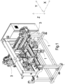
- a panel transportation device is integrated in a drilling machine or CNC work station for processing and particularly for drilling and milling panels of wood (and/or similar) intended for the production of furniture.
- the overall characteristics of the drill are like in the prior art; therefore, the machine is not illustrated or described in detail.
- the drill comprises a working plane, typically horizontal on which there lies a panel P that must be worked.
- the machine also provides for an inlet from which the panel is inserted, and to this purpose the inlet is reached by horizontal guides 1 that allow the panel to be supported and actually define the aforementioned working plane.
- the horizontal guides are parallel to one another and are arranged according to an advancement direction X of the panel P in the machine; the guides are also spaced apart by a variable distance based on the width of the panel along an axis Y perpendicular to X and defining with it the working plane of the panel itself. The variable distance thus allows the change of format of the panel being processed.
- a third vertical axis Z completes a 3D absolute Cartesian reference system.
- the working plane is acted upon by the tool-holder head of a drilling unit (of a known type, therefore not described in detail) indicated with 2 in the figures, which carries out the processing on the panel P.
- the latter (shown only schematically in figures 5a to 5d ) advances on the working plane according to the advancement direction X.
- the actuation of the drilling unit is controlled by a numerical control system CAM that, further to suitable setup of the mapping of the holes and processing to be carried out, moves the unit itself.
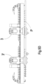
- the panel P is transported on the working plane by a transportation system shown in isolation in figures 5a to 5d .
- the transportation system according to the invention comprises two clamps 3, 3' independently mobile from one another.
- Each clamp is mobile in translation along the advancement direction X by means of brushless motors that engage on respective rack and pinion drive systems or another system like recirculating ball screws, etc. according to a known configuration.
- the clamps are positioned laterally at one of the two guides 1, so as to grip the side P1 of the panel P that projects beyond the same guide.
- the panel In an adaptation position the panel is engaged simultaneously with the first and the second clamp; however, the second clamp is open, and therefore the panel slides in it, driven only by the action of the first clamp. At this point, the second clamp 3' clamps the panel P for an exchange step.
- the simultaneous gripping of the panel by both of the clamps is practically instantaneous because it lasts a few milliseconds (less than 10 milliseconds).
- the panel is in movement; in order to grip the panel therefore the second clamp 3' must move in the open condition with a certain time advance and only when it has reached the same speed as the panel will it be switched by the CPU to the grip position.
- the first clamp 3 opens, releasing the grip.
- the second clamp 3' continues the movement at the same speed as the first clamp 3 and the panel P advances according to the direction X.
- the CPU calculates in real time the starting point of dynamic engagement (so-called dynamic "gantry") of the clamp to the panel, so as to ensure that when the coordinate according to the physical axis X has reached the speed identical to that of the virtual coordinate X', the clamp can be closed and the run point when the clamp closes on the piece will correspond to that of the pre-calculated target.
- the firmware calculates the space necessary to reach the speed of the virtual coordinate, taking into account that when it is reached it can also have a different speed, made available in advance by the numerical control.
- the calculation in offline mode has the advantage of not using memory resources that remain, on the other hand, available to the firmware for controlling the movement.
- the calculation of the engagement/disengagement positions is based on the run data of the clamps with respect to the physical axes and is carried out by the firmware. As mentioned above, the run of the two clamps is limited as a function of the size/bulk of the tool-holder heads. Depending on the predetermined position of the hole, the run data and the size of the tool-holder heads, the firmware determines the switch-on (grip position) and switch off (release) positions of the clamps.
- first clamp 3 and the second clamp 3' there is a moment at which both of the clamps are gripping the panel. This is permitted by the fact that the second clamp clamps the panel only at the moment when it has reached the same speed as it. This obviously requires a calculated time, dependent on the dynamics of the closing axis of the clamp to which a space travelled by the moving piece corresponds.
- the target positions of the trajectory pre-calculated by the firmware at subsequent time units are also used to carry out corrections to avoid errors in certain cases, such as milling on circumferences of very small radius, a case in which the engagement in real time between the virtual position and the real position of the clamps could autonomously start up the exchange procedure, activating and bringing to normal operating speed the clamp at rest when the virtual axis has already reversed its motion, while the exchange of the clamp in the reverse direction is actually needed.
- the CPU is capable of monitoring and controlling in real time the combined gripping/release steps of the clamps, comparing the real position of the clamps with the target position and knowing the movement speed of the panel and the mapping of the processing on it.
- the combined work of the clamps allows the panel to be moved for a potentially unlimited length (as already mentioned above), greater than the length given by the sum of the single runs of the clamps themselves. Therefore, the machine according to the invention is particularly advantageous because it can work even oversized pieces.
- the driving/transportation system according to the invention is particularly advantageous because it is extremely flexible and adaptable to pieces of various sizes. Moreover, it can be completely automated and managed remotely.
- the system is not very bulky but very efficient, in particular with reference to work speed and productivity, irrespective of the size of the panel.
- the clamps are preferably of the pneumatic type.
- the pneumatic feeding system of the clamps is not described in detail, since it is obvious for those skilled in the art to implement it in light of the operation of the clamps themselves described now.
Landscapes
- Engineering & Computer Science (AREA)
- Mechanical Engineering (AREA)
- Life Sciences & Earth Sciences (AREA)
- Wood Science & Technology (AREA)
- Forests & Forestry (AREA)
- Machines For Manufacturing Corrugated Board In Mechanical Paper-Making Processes (AREA)
- Jigs For Machine Tools (AREA)
- Feeding Of Workpieces (AREA)
Claims (4)
- Procédé permettant de déplacer un panneau (P) en bois ou autre matériau similaire dans une perceuse/fraiseuse, ladite machine comprenant une surface de travail sur laquelle travaille au moins une tête porte-outil et ledit panneau (P) est adapté à reposer et se déplacer le long d'une direction d'avancement (X), ladite machine comprenant en outre un système de transport de panneau pour le déplacement dudit panneau le long de ladite direction d'avancement, ledit système de transport de panneau comprenant une première et une seconde pince (3, 3') actionnées chacune par un système d'entraînement indépendant, lesdites première et seconde pinces coopérant l'une avec l'autre pour déplacer ledit panneau le long d'une trajectoire d'une longueur supérieure à la somme des courses de chaque pince individuelle, ledit procédé comprenant les étapes consistant à : - agencer ledit panneau au niveau d'une entrée de ladite machine sur une surface de travail, ladite surface de travail étant affectée par au moins une tête porte-outil (2) ; - positionner ledit panneau de sorte qu'il est affecté par une première pince (3) ; - faire fonctionner ladite première pince en saisissant ledit panneau (P) ; - déplacer ladite première pince selon une direction d'avancement (X) à une vitesse d'avancement vers une position cible ; ledit procédé étant en outre caractérisé en ce que : si ladite position cible se trouve au-delà d'une limite de course de ladite première pince (3) : - faire fonctionner ladite seconde pince (3') de sorte qu'elle affecte ledit panneau (P) dans une position différente par rapport à ladite première pince (3) ; - déplacer ladite seconde pince (3') de sorte qu'elle atteint la même vitesse d'avancement que ladite première pince le long dudit axe (X) dudit panneau ; - sans arrêter le mouvement dudit panneau, fermer dans une position de saisie ladite seconde pince sur ledit panneau lorsque ladite première pince est encore dans une position de saisie de sorte que, dans cette étape d'échange, les deux pinces saisissent simultanément ledit panneau en deux points différents de celui-ci ; - libérer ladite première pince (3) du panneau ; - déplacer ledit panneau le long dudit axe (X) sous l'effet de l'entraînement de ladite seconde pince (3') uniquement ; et dans lequel ladite première pince (3) a une course limitée positivement, et ladite seconde pince (3') a une course limitée négativement, moyennant quoi les limitations définissent des zones du panneau qui ne sont jamais mises en prise par l'une ou l'autre des deux pinces et où le traitement du panneau par ledit porte-outil est autorisé.
- Procédé selon la revendication 1, dans lequel ladite étape de saisie simultanée du panneau par les deux pinces est d'une durée inférieure à 10 millisecondes.
- Procédé selon la revendication 1 ou 2, dans lequel une pluralité de positions cibles sont précalculées pour un nombre correspondant d'unités de temps ultérieures.
- Machine permettant de percer/fraiser un panneau (P) en bois ou autre matériau similaire, comprenant une surface de travail sur laquelle travaille au moins une tête porte-outil et ledit panneau (P) est adapté à reposer et se déplacer le long d'une direction d'avancement (X), ladite machine comprenant en outre un système de transport de panneau pour le déplacement dudit panneau (P) le long de ladite direction d'avancement (X), ledit système de transport de panneau comprenant une première et une seconde pince (3, 3') chacune actionnée par un système d'entraînement indépendant, lesdites première et seconde pinces coopérant l'une avec l'autre pour déplacer ledit panneau le long d'une trajectoire d'une longueur supérieure à la somme des courses de chaque pince individuelle, ladite machine comprenant en outre une UC avec des instructions résidentes pour commander les systèmes d'entraînement desdites première et seconde pinces selon une séquence de mouvements coordonnés instruits et d'actionnements de saisie/libération de chaque pince par rapport à l'autre pince, caractérisée en ce que ladite UC, par le biais desdites instructions résidentes, est adaptée à exécuter les étapes du procédé selon l'une quelconque des revendications précédentes.
Applications Claiming Priority (1)
| Application Number | Priority Date | Filing Date | Title |
|---|---|---|---|
| ITFI2015A000133A ITFI20150133A1 (it) | 2015-05-08 | 2015-05-08 | Macchina a controllo numerico per la lavorazione di pannelli in legno con dispositivo di trascinamento perfezionato |
Publications (2)
| Publication Number | Publication Date |
|---|---|
| EP3106276A1 EP3106276A1 (fr) | 2016-12-21 |
| EP3106276B1 true EP3106276B1 (fr) | 2025-07-02 |
Family
ID=53794372
Family Applications (1)
| Application Number | Title | Priority Date | Filing Date |
|---|---|---|---|
| EP16168616.7A Active EP3106276B1 (fr) | 2015-05-08 | 2016-05-06 | Une machine a bois a controle numerique avec un systeme de d'approvisionnement en paneaux ameliore et une methode permettant de mouvoir un paneau de bois a l'interieur d'une machine permettant le travail du bois |
Country Status (2)
| Country | Link |
|---|---|
| EP (1) | EP3106276B1 (fr) |
| IT (1) | ITFI20150133A1 (fr) |
Families Citing this family (1)
| Publication number | Priority date | Publication date | Assignee | Title |
|---|---|---|---|---|
| IT201800005055A1 (it) | 2018-05-03 | 2019-11-03 | Macchina foratrice/fresatrice a controllo numerico per pannelli in legno con sistema di trattenimento ausiliario del pannello |
Citations (4)
| Publication number | Priority date | Publication date | Assignee | Title |
|---|---|---|---|---|
| DE10030997A1 (de) * | 1999-07-02 | 2001-01-11 | Biesse Spa | Anlage zum Bearbeiten von ebenen Körpern, insbesondere von Holztafeln |
| WO2002094500A1 (fr) * | 2001-05-21 | 2002-11-28 | Pade S.A.S. Di De Moliner Vinicio & C. | Poste de travail |
| DE102006019115A1 (de) * | 2005-04-27 | 2006-11-02 | Scm Group S.P.A. | Maschine, Methode und Zangenvorrichtung für eine Platte |
| EP2660023A2 (fr) * | 2012-05-03 | 2013-11-06 | BIESSE S.p.A. | Procédé et machine pour traiter des composants de bois ou similaire |
Family Cites Families (4)
| Publication number | Priority date | Publication date | Assignee | Title |
|---|---|---|---|---|
| DE10305570B4 (de) * | 2002-10-02 | 2016-01-28 | Hans Hundegger Maschinenbau | Verfahren und Bearbeitungsanlage für das Bearbeiten von Holzwerkstücken |
| IT1401082B1 (it) | 2010-07-26 | 2013-07-12 | Vitap Costruzioni Meccaniche S P A | Macchina foratrice a controllo numerico per pannelli in legno con gruppo forante perfezionato |
| IT1401081B1 (it) | 2010-07-26 | 2013-07-12 | Vitap Costruzioni Meccaniche S P A | Macchina foratrice a controllo numerico per pannelli in legno con dispositivo di trascinamento perfezionato |
| DE102013221725A1 (de) * | 2013-10-25 | 2015-04-30 | Weeke Bohrsysteme Gmbh | Verfahren und Vorrichtung zum Bearbeiten von Werkstücken |
-
2015
- 2015-05-08 IT ITFI2015A000133A patent/ITFI20150133A1/it unknown
-
2016
- 2016-05-06 EP EP16168616.7A patent/EP3106276B1/fr active Active
Patent Citations (4)
| Publication number | Priority date | Publication date | Assignee | Title |
|---|---|---|---|---|
| DE10030997A1 (de) * | 1999-07-02 | 2001-01-11 | Biesse Spa | Anlage zum Bearbeiten von ebenen Körpern, insbesondere von Holztafeln |
| WO2002094500A1 (fr) * | 2001-05-21 | 2002-11-28 | Pade S.A.S. Di De Moliner Vinicio & C. | Poste de travail |
| DE102006019115A1 (de) * | 2005-04-27 | 2006-11-02 | Scm Group S.P.A. | Maschine, Methode und Zangenvorrichtung für eine Platte |
| EP2660023A2 (fr) * | 2012-05-03 | 2013-11-06 | BIESSE S.p.A. | Procédé et machine pour traiter des composants de bois ou similaire |
Also Published As
| Publication number | Publication date |
|---|---|
| ITFI20150133A1 (it) | 2016-11-08 |
| EP3106276A1 (fr) | 2016-12-21 |
Similar Documents
| Publication | Publication Date | Title |
|---|---|---|
| EP1712337B1 (fr) | Centre d'usinage avec deux unités de travail avec moyens de manipulation de la pièce | |
| JP6773712B2 (ja) | ロボット加工システム | |
| EP0455095A1 (fr) | Machine combinée pour travailler des panneaux de bois à l'unité ou en paquets ou matériau similaire | |
| JP6487373B2 (ja) | ワーク固定装置 | |
| WO2016051342A1 (fr) | Machine-outil | |
| GB2510158A (en) | Robotic Structural Steel fabrication | |
| US20090053000A1 (en) | Compact High Precision Multiple Spindle Computer Controlled Machine Tool | |
| EP3106276B1 (fr) | Une machine a bois a controle numerique avec un systeme de d'approvisionnement en paneaux ameliore et une methode permettant de mouvoir un paneau de bois a l'interieur d'une machine permettant le travail du bois | |
| EP1247611B1 (fr) | Centre d'usinage à plusieurs axes, pour usinage multiple, en particulier pour le travail du bois | |
| EP3597359B1 (fr) | Machine-outil multibroches à commande numérique à réglage automatique avec dispositif de préhension de plaques minces et procédé d'usinage desdites plaques minces | |
| ITPC20110018A1 (it) | Centro di lavoro per la lavorazione del legno | |
| EP2361738A1 (fr) | Unité opérationnelle pour un centre d'usinage | |
| EP1792697B1 (fr) | Machine à fabriquer des cadres de porte | |
| EP1623805B1 (fr) | Machine à contrôle numérique pour la réalisation d'éléments de jonction | |
| EP2681024A2 (fr) | Procédé et machine de traitement de panneaux de bois ou similaires | |
| US12583035B2 (en) | Combined processing machine | |
| EP3900901B1 (fr) | Machine double face pour traitement industriel | |
| US11780037B2 (en) | Gripping machine for articles | |
| CN111250995B (zh) | 拖钩螺母生产设备及其加工工艺 | |
| EP4691722A1 (fr) | Machine pour le traitement simultané de pièces et procédé pour le traitement simultané de pièces avec cette machine | |
| US6095727A (en) | Working head for numeric-control machine tools | |
| ITMI20011041A1 (it) | Apparecchiatura per la lavorazione di pezzi | |
| JPH04267101A (ja) | 木材接合部のほぞ加工装置 | |
| JPH08197357A (ja) | 被加工物のクランプ装置と加工装置 | |
| JPH04267104A (ja) | タレット式木材加工機の切削装置 |
Legal Events
| Date | Code | Title | Description |
|---|---|---|---|
| PUAI | Public reference made under article 153(3) epc to a published international application that has entered the european phase |
Free format text: ORIGINAL CODE: 0009012 |
|
| STAA | Information on the status of an ep patent application or granted ep patent |
Free format text: STATUS: THE APPLICATION HAS BEEN PUBLISHED |
|
| AK | Designated contracting states |
Kind code of ref document: A1 Designated state(s): AL AT BE BG CH CY CZ DE DK EE ES FI FR GB GR HR HU IE IS IT LI LT LU LV MC MK MT NL NO PL PT RO RS SE SI SK SM TR |
|
| AX | Request for extension of the european patent |
Extension state: BA ME |
|
| STAA | Information on the status of an ep patent application or granted ep patent |
Free format text: STATUS: REQUEST FOR EXAMINATION WAS MADE |
|
| 17P | Request for examination filed |
Effective date: 20170615 |
|
| RBV | Designated contracting states (corrected) |
Designated state(s): AL AT BE BG CH CY CZ DE DK EE ES FI FR GB GR HR HU IE IS IT LI LT LU LV MC MK MT NL NO PL PT RO RS SE SI SK SM TR |
|
| STAA | Information on the status of an ep patent application or granted ep patent |
Free format text: STATUS: EXAMINATION IS IN PROGRESS |
|
| 17Q | First examination report despatched |
Effective date: 20201113 |
|
| GRAP | Despatch of communication of intention to grant a patent |
Free format text: ORIGINAL CODE: EPIDOSNIGR1 |
|
| STAA | Information on the status of an ep patent application or granted ep patent |
Free format text: STATUS: GRANT OF PATENT IS INTENDED |
|
| INTG | Intention to grant announced |
Effective date: 20250127 |
|
| GRAS | Grant fee paid |
Free format text: ORIGINAL CODE: EPIDOSNIGR3 |
|
| GRAA | (expected) grant |
Free format text: ORIGINAL CODE: 0009210 |
|
| STAA | Information on the status of an ep patent application or granted ep patent |
Free format text: STATUS: THE PATENT HAS BEEN GRANTED |
|
| AK | Designated contracting states |
Kind code of ref document: B1 Designated state(s): AL AT BE BG CH CY CZ DE DK EE ES FI FR GB GR HR HU IE IS IT LI LT LU LV MC MK MT NL NO PL PT RO RS SE SI SK SM TR |
|
| REG | Reference to a national code |
Ref country code: GB Ref legal event code: FG4D |
|
| REG | Reference to a national code |
Ref country code: CH Ref legal event code: EP |
|
| REG | Reference to a national code |
Ref country code: DE Ref legal event code: R096 Ref document number: 602016092733 Country of ref document: DE |
|
| REG | Reference to a national code |
Ref country code: IE Ref legal event code: FG4D |
|
| REG | Reference to a national code |
Ref country code: NL Ref legal event code: MP Effective date: 20250702 |
|
| PG25 | Lapsed in a contracting state [announced via postgrant information from national office to epo] |
Ref country code: PT Free format text: LAPSE BECAUSE OF FAILURE TO SUBMIT A TRANSLATION OF THE DESCRIPTION OR TO PAY THE FEE WITHIN THE PRESCRIBED TIME-LIMIT Effective date: 20251103 |
|
| PG25 | Lapsed in a contracting state [announced via postgrant information from national office to epo] |
Ref country code: NL Free format text: LAPSE BECAUSE OF FAILURE TO SUBMIT A TRANSLATION OF THE DESCRIPTION OR TO PAY THE FEE WITHIN THE PRESCRIBED TIME-LIMIT Effective date: 20250702 |
|
| PG25 | Lapsed in a contracting state [announced via postgrant information from national office to epo] |
Ref country code: IS Free format text: LAPSE BECAUSE OF FAILURE TO SUBMIT A TRANSLATION OF THE DESCRIPTION OR TO PAY THE FEE WITHIN THE PRESCRIBED TIME-LIMIT Effective date: 20251102 |
|
| PG25 | Lapsed in a contracting state [announced via postgrant information from national office to epo] |
Ref country code: NO Free format text: LAPSE BECAUSE OF FAILURE TO SUBMIT A TRANSLATION OF THE DESCRIPTION OR TO PAY THE FEE WITHIN THE PRESCRIBED TIME-LIMIT Effective date: 20251002 |
|
| REG | Reference to a national code |
Ref country code: LT Ref legal event code: MG9D |
|
| PG25 | Lapsed in a contracting state [announced via postgrant information from national office to epo] |
Ref country code: FI Free format text: LAPSE BECAUSE OF FAILURE TO SUBMIT A TRANSLATION OF THE DESCRIPTION OR TO PAY THE FEE WITHIN THE PRESCRIBED TIME-LIMIT Effective date: 20250702 |
|
| PG25 | Lapsed in a contracting state [announced via postgrant information from national office to epo] |
Ref country code: HR Free format text: LAPSE BECAUSE OF FAILURE TO SUBMIT A TRANSLATION OF THE DESCRIPTION OR TO PAY THE FEE WITHIN THE PRESCRIBED TIME-LIMIT Effective date: 20250702 |
|
| PG25 | Lapsed in a contracting state [announced via postgrant information from national office to epo] |
Ref country code: GR Free format text: LAPSE BECAUSE OF FAILURE TO SUBMIT A TRANSLATION OF THE DESCRIPTION OR TO PAY THE FEE WITHIN THE PRESCRIBED TIME-LIMIT Effective date: 20251003 |
|
| PG25 | Lapsed in a contracting state [announced via postgrant information from national office to epo] |
Ref country code: SE Free format text: LAPSE BECAUSE OF FAILURE TO SUBMIT A TRANSLATION OF THE DESCRIPTION OR TO PAY THE FEE WITHIN THE PRESCRIBED TIME-LIMIT Effective date: 20250702 Ref country code: CZ Free format text: LAPSE BECAUSE OF FAILURE TO SUBMIT A TRANSLATION OF THE DESCRIPTION OR TO PAY THE FEE WITHIN THE PRESCRIBED TIME-LIMIT Effective date: 20250702 |
|
| PG25 | Lapsed in a contracting state [announced via postgrant information from national office to epo] |
Ref country code: LV Free format text: LAPSE BECAUSE OF FAILURE TO SUBMIT A TRANSLATION OF THE DESCRIPTION OR TO PAY THE FEE WITHIN THE PRESCRIBED TIME-LIMIT Effective date: 20250702 |
|
| PG25 | Lapsed in a contracting state [announced via postgrant information from national office to epo] |
Ref country code: BG Free format text: LAPSE BECAUSE OF FAILURE TO SUBMIT A TRANSLATION OF THE DESCRIPTION OR TO PAY THE FEE WITHIN THE PRESCRIBED TIME-LIMIT Effective date: 20250702 Ref country code: PL Free format text: LAPSE BECAUSE OF FAILURE TO SUBMIT A TRANSLATION OF THE DESCRIPTION OR TO PAY THE FEE WITHIN THE PRESCRIBED TIME-LIMIT Effective date: 20250702 |
|
| PG25 | Lapsed in a contracting state [announced via postgrant information from national office to epo] |
Ref country code: RS Free format text: LAPSE BECAUSE OF FAILURE TO SUBMIT A TRANSLATION OF THE DESCRIPTION OR TO PAY THE FEE WITHIN THE PRESCRIBED TIME-LIMIT Effective date: 20251002 |
|
| PG25 | Lapsed in a contracting state [announced via postgrant information from national office to epo] |
Ref country code: ES Free format text: LAPSE BECAUSE OF FAILURE TO SUBMIT A TRANSLATION OF THE DESCRIPTION OR TO PAY THE FEE WITHIN THE PRESCRIBED TIME-LIMIT Effective date: 20250702 |
|
| PG25 | Lapsed in a contracting state [announced via postgrant information from national office to epo] |
Ref country code: SM Free format text: LAPSE BECAUSE OF FAILURE TO SUBMIT A TRANSLATION OF THE DESCRIPTION OR TO PAY THE FEE WITHIN THE PRESCRIBED TIME-LIMIT Effective date: 20250702 |
|
| PG25 | Lapsed in a contracting state [announced via postgrant information from national office to epo] |
Ref country code: DK Free format text: LAPSE BECAUSE OF FAILURE TO SUBMIT A TRANSLATION OF THE DESCRIPTION OR TO PAY THE FEE WITHIN THE PRESCRIBED TIME-LIMIT Effective date: 20250702 |
|
| PG25 | Lapsed in a contracting state [announced via postgrant information from national office to epo] |
Ref country code: EE Free format text: LAPSE BECAUSE OF FAILURE TO SUBMIT A TRANSLATION OF THE DESCRIPTION OR TO PAY THE FEE WITHIN THE PRESCRIBED TIME-LIMIT Effective date: 20250702 Ref country code: SK Free format text: LAPSE BECAUSE OF FAILURE TO SUBMIT A TRANSLATION OF THE DESCRIPTION OR TO PAY THE FEE WITHIN THE PRESCRIBED TIME-LIMIT Effective date: 20250702 |