EP3106332B1 - Aufblasbares schlauchförmiges element zum verlegen von schutzplanen - Google Patents
Aufblasbares schlauchförmiges element zum verlegen von schutzplanen Download PDFInfo
- Publication number
- EP3106332B1 EP3106332B1 EP15172764.1A EP15172764A EP3106332B1 EP 3106332 B1 EP3106332 B1 EP 3106332B1 EP 15172764 A EP15172764 A EP 15172764A EP 3106332 B1 EP3106332 B1 EP 3106332B1
- Authority
- EP
- European Patent Office
- Prior art keywords
- tarpaulin
- combination
- posts
- tubular elements
- elements
- Prior art date
- Legal status (The legal status is an assumption and is not a legal conclusion. Google has not performed a legal analysis and makes no representation as to the accuracy of the status listed.)
- Active
Links
Images



Classifications
-
- B—PERFORMING OPERATIONS; TRANSPORTING
- B60—VEHICLES IN GENERAL
- B60J—WINDOWS, WINDSCREENS, NON-FIXED ROOFS, DOORS, OR SIMILAR DEVICES FOR VEHICLES; REMOVABLE EXTERNAL PROTECTIVE COVERINGS SPECIALLY ADAPTED FOR VEHICLES
- B60J7/00—Non-fixed roofs; Roofs with movable panels, e.g. rotary sunroofs
- B60J7/08—Non-fixed roofs; Roofs with movable panels, e.g. rotary sunroofs of non-sliding type, i.e. movable or removable roofs or panels, e.g. let-down tops or roofs capable of being easily detached or of assuming a collapsed or inoperative position
- B60J7/10—Non-fixed roofs; Roofs with movable panels, e.g. rotary sunroofs of non-sliding type, i.e. movable or removable roofs or panels, e.g. let-down tops or roofs capable of being easily detached or of assuming a collapsed or inoperative position readily detachable, e.g. tarpaulins with frames, or fastenings for tarpaulins
- B60J7/102—Readily detachable tarpaulins, e.g. for utility vehicles; Frames therefor
Definitions
- the present invention addresses the field of covers, particularly protective tarpaulins for covering heavy truck bodies.
- EP2378022 discloses a system that allows an operator to automatically deploy and lay a tarpaulin on a truck body.
- An inflatable tarpaulin is employed, which is first wound and accommodated in the gap between the cabin and the body, and is inflated to be gradually deployed on the body, without requiring any manual action by the operator.
- the object of the present invention is to solve at least some of the above problems by providing a cover with a system that allows self-placement of a protective tarpaulin with the operator on the ground, without using structures external to or integrated in the tractor of the vehicle, and requiring as little action by the operator as possible.
- the invention fulfills the above object using pneumatic structures that can be assembled together.
- the core of the invention is represented by a modular element that can be inflated to a working shape, from an initial rest shape in which the element is fully or partially deflated.
- the element has anchor points for tubular elements of the same type, such that it may form a multiplicity of support structures for a protective tarpaulin, which may thus be laid in different manners, when such tubular element/s are coupled to said tarpaulin.
- the tarpaulin is disengaged from the support structure, which is movable and modular to adapt to various laying needs, without requiring the use of components to be installed on the vehicle. This is ensured by the use of pneumatic elements, which are designed to be associated with the tarpaulin in multiple highly advantageous configurations.
- the inflatable element which is typically made of a plastic or elastic material is advantageously inserted in a substantially cylindrical fabric envelope.
- abrasion-resistant technical fabrics such as Dacron, Kevron, or Cordura
- special seams which prevent tearing when the tube is inflated to high pressures, provides optimal results in terms of size of the structure and rigidity.
- the tubular element has an annular appendix at one end, which is designed to be coupled to corresponding hooks or eyelets of tubular elements of the same type, to form modular T-shaped structures.
- the element typically extends along a straight axis, and has at least one transverse tape with an eyelet for engagement with corresponding eyelets or hooks associated with further tubular elements or with the tarpaulin with which the element is designed to be coupled when it is installed.
- a handle, particularly having a longitudinal extension, is advantageously provided at one end, particularly the end opposite to that with the annular appendix.
- the element may comprise a longitudinal fabric or hook-and-loop strap of a fastening stretch or Velcro assembly.
- the corresponding fabric or hook-and-loop strap of the pair is placed on the tarpaulin, typically in a peripheral position, to provide removable coupling.
- three tubular elements are used to form a support structure for a tarpaulin.
- Two elements are connected by the respective annular appendix to a pair of eyelets or hooks of the third tubular elements, typically proximate to the center to form a double-T configuration composed of a cross member and a pair of posts in operation with inflated elements.
- the invention relates to a protective tarpaulin for covering a heavy truck body that has elements for coupling or containing one or more tubular elements of the invention, to form a support structure for said tarpaulin provided in combination with said tubular elements.
- the cross member is attached at one side of the tarpaulin for the tarpaulin to be stretched along its length or width and for an operator to act upon the posts to move the tarpaulin over the body.
- the cross member may be attached to the tarpaulin in a center position, for a portion of the tarpaulin to be stretched and folded along its length or width and for an operator to act upon the posts to move the tarpaulin over the body.
- the cross member may be equipped with a reinforcement rod.
- the tubular elements are attached or integrated along two opposite sides of the tarpaulin to form a pair of ribs of the tarpaulin when they assume the working shape.
- the tarpaulin and/or tubular elements have fastening elements, e.g. of magnetic type, to attach the structure to the body to be covered.
- the tarpaulin may be advantageously provided in combination with a truck body, for instance having the shape of a parallelepiped, with the tarpaulin being attached to its side surface substantially along the entire height, or proximate to its maximum height, such that it may be folded back onto its upper surface once the tubular elements have assumed the working shape.
- the tarpaulin may be provided in combination with a single tubular element whose working shape is an arc-shape.
- the tarpaulin is attached to the tubular element by loops like in curtains.
- a portal-like frame composed of a pair of posts and a cross member.
- the posts have rolling elements at their base, to allow translation of the cross member of the portal above the body when the posts are moved at the opposite sides of the body.
- the tarpaulin is initially wound on the cross member of the portal, and is attached proximate to the top of a side surface of the body, e.g. by magnets, and is unwound therefrom as the portal is translated along the length of the body.
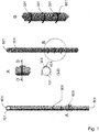
- Figure 1 shows a preferred embodiment of a tubular element of the present invention, which is designed to be used as a support element for laying a tarpaulin on a heavy truck body.
- the guiding principle of the present invention is also applicable to tarpaulins designed for a variety of other applications.
- the tubular element of the figures which is drawn to a scale of 1 to 10, has the shape of a cylinder having a length of 5 m and a diameter of 25 cm. These values have been found to be appropriate for tarpaulins of the type and size as commonly used for covering truck bodies, but may be obviously modified according to the particular type of installation.
- Removable structures with inflatable tubes ensure light weight and minimize space requirements. Nevertheless, since tarpaulins designed for use as covers are very large and heavy, a certain level of rigidity must be imparted to the structure to support the distributed weight of these tarpaulins. On the other hand, since the structure is required to have a small size to facilitate transport and use by a single operator, the tubes shall be inflated to a greater pressure, and any deformation thereof shall be prevented. Therefore, the element is required to be formed within a well-defined shape, such that it will not be deformed when it is inflated to significant pressures, possibly of 7-8 bar. In view of the above, according to the invention the inflatable element, which is typically made of a plastic or elastic material is inserted in a substantially cylindrical fabric envelope. The use of abrasion-resistant technical fabrics, such as Dacron, Kevron, or Cordura, and special seams, which prevent tearing when the tube is inflated to high pressures, allows fulfillment of the above purposes.
- abrasion-resistant technical fabrics
- the tubular element is made of a plastic material with an outer Cordura skin 101. It has a 2.5 m longitudinal Velcro strap 201, for stretch coupling to a tarpaulin and three annular tapes 301 with an eyelet 401, arranged with a spacing of 50 cm, starting from 1.2 m from the end 501.
- the tapes 301 are arranged all around the tubular element.
- a handle 601 whose size allows grasping thereof by one hand, is longitudinally arranged, proximate to one of the tapes 301, at 1.1 m from the end 501.
- the opposite end 701 has an appendix at its top, which is formed into a longitudinal coupling eyelet 801 to create T- or double T-shaped configurations.
- the tubular element may be attached to the tarpaulin using the Velcro strap or one or more fastening eyelets.
- one or more tubular elements may be integrated in the tarpaulin, e.g. by utilizing one or more pockets in which said elements may be received, and thereby forming highly compact structures.
- the number and position of the anchors may also change, to create modular elements with an optimized versatility.
- the tubes are arranged to form a double T-(TT) shape, that maintains the tarpaulin well-stretched over its entire length, and two posts, having the dual purpose of moving the tarpaulin over the body and preventing contact with the material contained therein.
- the thrust configuration may envisage some differences according to the relevant working area, i.e. the short side or the long side, with pros and cons according to the selected configuration.
- 3 tubes are also arranged in a double T (TT) - shape, and a reinforcement bar is added to increase the rigidity of the inflatable structure.
- TT double T
- the throwing configuration may envisage some differences according to the relevant working area, i.e. the short side or the long side, with pros and cons according to the selected configuration.
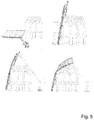
- the tarpaulin is initially attached by magnets along the long side, and three equally-spaced tubes, arranged perpendicular to the linger side, act as thrust/support ribs.
- the tubes are integrated or attached to the tarpaulin and as they are inflated they vertically stretch the tarpaulin, which is later folded back by the operator using ropes, to cover the truck body.
- the tubes are inflated on the ground before the folding step, to be later arranged separate from the tarpaulin to form a kind of frame structure. Then the operator places the structure with a vertical orientation against one side of the truck body. Using one or more magnets, the tarpaulin is attached proximate to the top of the body and is later folded back above the body with the help of ropes, as shown in the last image of the sequence of Fig. 5 .
- the tarpaulin may be positioned without requiring excessive care, but must be prepared before the covering step.
- a single tube which acts as a rod, with the tarpaulin attached at one of its ends.
- the covering step may be carried out either on the long side or on the short side of the truck body. In the latter case, the cover of the entire body should be divided into two parts.
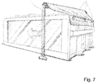
- the portal-like structure ( Fig. 7 ) is still obtained using 3 inflatable tubes, but uses wheels at the base of the portal posts, thereby avoiding the need of dragging the tubes on the ground, which would be damaged thereby.
- the operator inflates the portal structure on the ground and later places it against the short side before pulling it.
- tubular elements may be designed for use as a support for tarpaulins for swimming pools, cars and bulky containers of any kind, using a variety of assembly configurations with any number of elements whatever. The above is without departure from the guiding principle disclosed above and claimed below.
Landscapes
- Engineering & Computer Science (AREA)
- Mechanical Engineering (AREA)
- Tents Or Canopies (AREA)
Claims (11)
- Kombination einer Schutzplane zum Abdecken eines Körpers von schweren Lastkraftwagen mit einem oder mehreren rohrförmigen Elementen, wobei die Plane Elemente zur Kopplung oder Aufnahme eines oder mehrerer der genannten rohrförmigen Elemente aufweist; wobei die genannten rohrförmigen Elemente aus einer Ausgangsruheform, in der das Element entleert oder teilweise entleert ist, in eine Arbeitsform aufblasbar sind, dadurch gekennzeichnet, dass das rohrförmige Element modular ausgebildet ist und Ankerpunkte (401, 801) für gleichartige Rohrelemente aufweist, so dass es eine Vielzahl von Stützstrukturen für die Schutzplane bilden kann, die somit auf unterschiedliche Weise verlegt werden kann, wenn ein solches rohrförmiges Element oder solche rohrförmigen Elemente mit der Plane gekoppelt ist/sind und dass jedes rohrförmige Element an einem Ende (701) einen ringförmigen Ansatz (801) aufweist, der dazu ausgebildet ist, mit entsprechenden Haken (401) oder Ösen von gleichartigen Rohrelementen gekoppelt zu werden, um T-förmige Strukturen zu bilden; wobei das mindestens eine rohrförmige Element sich entlang einer geraden Achse erstreckt und mindestens ein Querband (301) mit einer Öse (401) zum Eingriff mit entsprechenden Ösen (401) oder Haken aufweist, die weiteren rohrförmigen Elementen oder der Plane zugeordnet sind, mit denen das Element beim Einbau gekoppelt ist.
- Kombination nach Anspruch 1, dadurch gekennzeichnet, dass sie aus einem Kunststoff oder einem elastischen Material besteht, das mit einem technischen Gewebe, nämlich Dacron, Kevlar oder Cordura, verkleidet ist, das eine Aufrechterhaltung der Arbeitsform definiert und sicherstellt.
- Kombination nach Anspruch 1 oder 2, dadurch gekennzeichnet, dass sie an einem Ende, insbesondere dem dem ringförmigen Ansatz gegenüberliegenden Ende, einen Griff (601), insbesondere mit einer Längserstreckung, aufweist.
- Kombination nach einem oder mehreren der vorhergehenden Ansprüche, dadurch gekennzeichnet, dass sie ein längserstrecktes Gewebe oder Klettband (201) einer Befestigungsstrecke oder Velcro-Anordnung umfasst, wobei das entsprechende Gewebe oder Klettband der Anordnung zur Verbindung mit der Plane zur lösbaren Kopplung des Elements mit der Plane vorgesehen ist.
- Kombination nach einem oder mehreren der vorhergehenden Ansprüche, welche drei rohrförmige Elemente umfasst, wobei zwei Elemente über ihren jeweiligen ringförmigen Ansatz mit einem Paar von Ösen oder Haken des dritten rohrförmigen Elements verbunden sind, wobei das Paar von Ösen oder Haken des dritten Elements in der Nähe der Mitte angeordnet ist, um im Betrieb eine Doppel-T-Konfiguration mit einer Traverse und einem Paar von Ständern zu bilden.
- Kombination nach Anspruch 5, dadurch gekennzeichnet, dass es drei Rohre zur Bildung einer Doppel-T-förmigen Tragstruktur mit einer Traverse und zwei Ständer vorgesehen sind, wobei die Traverse an einer Seite der Plane befestigt ist, damit die Plane entlang ihrer Länge oder Breite gestrafft wird und damit der Bediener auf die Ständer einwirkt, um die Plane über den Körper zu bewegen.
- Kombination nach Anspruch 5, dadurch gekennzeichnet, dass drei Rohre vorgesehen sind, um eine Doppel-T-förmige Tragstruktur mit einer Traverse und zwei Ständer zu bilden, wobei die Traverse in einer Mittelposition an der Plane befestigt ist, damit ein Abschnitt der Plane entlang ihrer Länge oder Breite gestrafft und gefaltet wird und damit ein Bediener auf die Ständer einwirkt, um die Plane über den Körper zu bewegen, wobei ein Verstärkungsstab vorgesehen ist, um der aufblasbaren Struktur weitere Steifigkeit zu verleihen.
- Kombination nach Anspruch in einem oder mehreren der vorhergehenden Ansprüche, dadurch gekennzeichnet, dass die rohrförmigen Elemente entlang zweier gegenüberliegender Seiten der Plane befestigt oder integriert sind, um als ein Paar von Rippen der Plane zu wirken, wenn sie die Arbeitsform annehmen, wobei die Plane und/oder die rohrförmigen Elemente Befestigungselemente, wie Magnete, aufweisen, um die Struktur an dem zu bedeckenden Lkw-Körper zu befestigen.
- Kombination nach Anspruch 8, dadurch gekennzeichnet, dass sie in Kombination mit einem die Form eines Parallelepipeds aufweisenden LKW-Körper vorgesehen ist, wobei die Plane an einer Seitenfläche derselben im Wesentlichen entlang der gesamten Höhe oder in der Nähe seiner maximalen Höhe befestigt ist, so dass sie auf seine Oberfläche zurückgefaltet werden kann, sobald die rohrförmigen Elemente die Arbeitsform angenommen haben.
- Kombination nach einem oder mehreren der vorhergehenden Ansprüche, dadurch gekennzeichnet, dass drei rohrförmige Elemente zu einem Portal zusammengesetzt sind, das aus einem Paar von Ständern und einer Traverse besteht, wobei die Basis der Ständer mit Rollelementen derart ausgestattet ist, dass die Traverse des Portals beim Bewegen der Ständer an den gegenüberliegenden Seiten des Körpers über den LKW-Körper verfahren wird, wobei die Plane zunächst auf die Traverse des Portals aufgewickelt ist und beim Verfahren des Portals entlang der Körperlänge abgewickelt wird.
- Kombination nach Anspruch 10, dadurch gekennzeichnet, dass sie in Kombination mit einem LKW-Körper vorgesehen ist, wobei die Plane in der Nähe der Oberseite einer Seitenfläche des Körpers, z. B. durch Magnete, angebracht ist, damit beim Verfahren des Portals die Plane über den Körper entfaltet wird.
Priority Applications (1)
| Application Number | Priority Date | Filing Date | Title |
|---|---|---|---|
| EP15172764.1A EP3106332B1 (de) | 2015-06-18 | 2015-06-18 | Aufblasbares schlauchförmiges element zum verlegen von schutzplanen |
Applications Claiming Priority (1)
| Application Number | Priority Date | Filing Date | Title |
|---|---|---|---|
| EP15172764.1A EP3106332B1 (de) | 2015-06-18 | 2015-06-18 | Aufblasbares schlauchförmiges element zum verlegen von schutzplanen |
Publications (2)
| Publication Number | Publication Date |
|---|---|
| EP3106332A1 EP3106332A1 (de) | 2016-12-21 |
| EP3106332B1 true EP3106332B1 (de) | 2020-04-15 |
Family
ID=53489832
Family Applications (1)
| Application Number | Title | Priority Date | Filing Date |
|---|---|---|---|
| EP15172764.1A Active EP3106332B1 (de) | 2015-06-18 | 2015-06-18 | Aufblasbares schlauchförmiges element zum verlegen von schutzplanen |
Country Status (1)
| Country | Link |
|---|---|
| EP (1) | EP3106332B1 (de) |
Cited By (1)
| Publication number | Priority date | Publication date | Assignee | Title |
|---|---|---|---|---|
| US12403813B2 (en) | 2022-03-03 | 2025-09-02 | Toyota Motor Engineering & Manufacturing North America, Inc. | Apparatus for preventing cargo movement in a vehicle |
Citations (2)
| Publication number | Priority date | Publication date | Assignee | Title |
|---|---|---|---|---|
| US3994102A (en) * | 1974-05-06 | 1976-11-30 | Alley Friends | Inflatable element and system |
| FR2575504A1 (fr) * | 1985-01-02 | 1986-07-04 | Muracciole Francois | Dispositif gonflable permettant la construction de structures triangulees |
Family Cites Families (7)
| Publication number | Priority date | Publication date | Assignee | Title |
|---|---|---|---|---|
| US5042663A (en) * | 1989-05-05 | 1991-08-27 | Richard Heinrich | Joinable inflatable bladders for packaging |
| GB9617388D0 (en) * | 1996-08-19 | 1996-10-02 | Neill Rory O | Protective cover for vehicles |
| CN2276429Y (zh) * | 1996-11-04 | 1998-03-18 | 黄宇 | 充气汽车篷 |
| FI107902B (fi) * | 1998-12-09 | 2001-10-31 | Upm Kymmene Corp | Kuormapeite |
| NL1033362C2 (nl) * | 2007-02-08 | 2008-08-11 | Antonie Richard Verhoeven | Afdekken van transportcontainers. |
| FR2947489B1 (fr) * | 2009-07-06 | 2011-10-28 | Andre Sassi | Systeme de bache de protection pour vehicule automobile. |
| FR2958948A1 (fr) | 2010-04-14 | 2011-10-21 | Gurdebeke Sa | Dispositif et procede de bachage/debachage |
-
2015
- 2015-06-18 EP EP15172764.1A patent/EP3106332B1/de active Active
Patent Citations (2)
| Publication number | Priority date | Publication date | Assignee | Title |
|---|---|---|---|---|
| US3994102A (en) * | 1974-05-06 | 1976-11-30 | Alley Friends | Inflatable element and system |
| FR2575504A1 (fr) * | 1985-01-02 | 1986-07-04 | Muracciole Francois | Dispositif gonflable permettant la construction de structures triangulees |
Cited By (1)
| Publication number | Priority date | Publication date | Assignee | Title |
|---|---|---|---|---|
| US12403813B2 (en) | 2022-03-03 | 2025-09-02 | Toyota Motor Engineering & Manufacturing North America, Inc. | Apparatus for preventing cargo movement in a vehicle |
Also Published As
| Publication number | Publication date |
|---|---|
| EP3106332A1 (de) | 2016-12-21 |
Similar Documents
| Publication | Publication Date | Title |
|---|---|---|
| US20230089529A1 (en) | Shading system and method of use | |
| US9187191B1 (en) | Stretch skin receptacle for space object capture and release | |
| US9580095B2 (en) | Mobile cart | |
| US8286284B2 (en) | Rapid intervention drag stretcher devices | |
| US9708035B1 (en) | Variable length inflatable ramp launch and recovery system | |
| EP3021807B1 (de) | Zusammenklappbare tragbahre | |
| US9220647B1 (en) | Rigid collapsible litter | |
| EP2549463B1 (de) | Signalisierungsvorrichtung zur Anzeige von Warnungen oder Verkehrsschildern sowie Fahrzeug mit solch einer Signalisierungsvorrichtung | |
| EP3335994B1 (de) | Eine aufblasbare evakuierungsvorrichtung | |
| EP3106332A1 (de) | Aufblasbares schlauchförmiges element zum verlegen von schutzplanen | |
| EP2670926A1 (de) | Aufblasbarer balken | |
| WO2018172728A1 (en) | Tubular mast assembly methods for errecting and disassembling | |
| AU2014286914B2 (en) | A support structure | |
| CN117677575A (zh) | 用于展开卷起的卷轴的装置 | |
| US20110308743A1 (en) | Device and method for covering/uncovering a structure using a tarpaulin | |
| EP2172412A1 (de) | Vorrichtung zur Stabilisierung von Krankenliegen | |
| KR101639173B1 (ko) | 천막 장치 | |
| WO2016072239A1 (ja) | 気球格納箱、気球運搬装置、及び係留気球を放球する方法 | |
| US20200062058A1 (en) | Off-road recovery anchor | |
| US20230134608A1 (en) | Multi-purpose mat system | |
| RU2824684C1 (ru) | Эвакуационный робототехнический комплекс | |
| KR102950248B1 (ko) | 사다리 | |
| KR101666637B1 (ko) | 왕복운동용 로드의 보호장치 | |
| EP4252729A1 (de) | Rettungssystem für raumexplorer | |
| JP5121871B2 (ja) | 天幕被覆操作用補助具 |
Legal Events
| Date | Code | Title | Description |
|---|---|---|---|
| PUAI | Public reference made under article 153(3) epc to a published international application that has entered the european phase |
Free format text: ORIGINAL CODE: 0009012 |
|
| STAA | Information on the status of an ep patent application or granted ep patent |
Free format text: STATUS: THE APPLICATION HAS BEEN PUBLISHED |
|
| AK | Designated contracting states |
Kind code of ref document: A1 Designated state(s): AL AT BE BG CH CY CZ DE DK EE ES FI FR GB GR HR HU IE IS IT LI LT LU LV MC MK MT NL NO PL PT RO RS SE SI SK SM TR |
|
| AX | Request for extension of the european patent |
Extension state: BA ME |
|
| STAA | Information on the status of an ep patent application or granted ep patent |
Free format text: STATUS: REQUEST FOR EXAMINATION WAS MADE |
|
| 17P | Request for examination filed |
Effective date: 20170615 |
|
| RBV | Designated contracting states (corrected) |
Designated state(s): AL AT BE BG CH CY CZ DE DK EE ES FI FR GB GR HR HU IE IS IT LI LT LU LV MC MK MT NL NO PL PT RO RS SE SI SK SM TR |
|
| GRAP | Despatch of communication of intention to grant a patent |
Free format text: ORIGINAL CODE: EPIDOSNIGR1 |
|
| STAA | Information on the status of an ep patent application or granted ep patent |
Free format text: STATUS: GRANT OF PATENT IS INTENDED |
|
| INTG | Intention to grant announced |
Effective date: 20191112 |
|
| GRAS | Grant fee paid |
Free format text: ORIGINAL CODE: EPIDOSNIGR3 |
|
| GRAA | (expected) grant |
Free format text: ORIGINAL CODE: 0009210 |
|
| STAA | Information on the status of an ep patent application or granted ep patent |
Free format text: STATUS: THE PATENT HAS BEEN GRANTED |
|
| AK | Designated contracting states |
Kind code of ref document: B1 Designated state(s): AL AT BE BG CH CY CZ DE DK EE ES FI FR GB GR HR HU IE IS IT LI LT LU LV MC MK MT NL NO PL PT RO RS SE SI SK SM TR |
|
| REG | Reference to a national code |
Ref country code: CH Ref legal event code: EP |
|
| REG | Reference to a national code |
Ref country code: DE Ref legal event code: R096 Ref document number: 602015050613 Country of ref document: DE |
|
| REG | Reference to a national code |
Ref country code: IE Ref legal event code: FG4D |
|
| REG | Reference to a national code |
Ref country code: AT Ref legal event code: REF Ref document number: 1256852 Country of ref document: AT Kind code of ref document: T Effective date: 20200515 |
|
| REG | Reference to a national code |
Ref country code: NL Ref legal event code: MP Effective date: 20200415 |
|
| REG | Reference to a national code |
Ref country code: LT Ref legal event code: MG4D |
|
| PG25 | Lapsed in a contracting state [announced via postgrant information from national office to epo] |
Ref country code: SE Free format text: LAPSE BECAUSE OF FAILURE TO SUBMIT A TRANSLATION OF THE DESCRIPTION OR TO PAY THE FEE WITHIN THE PRESCRIBED TIME-LIMIT Effective date: 20200415 Ref country code: NL Free format text: LAPSE BECAUSE OF FAILURE TO SUBMIT A TRANSLATION OF THE DESCRIPTION OR TO PAY THE FEE WITHIN THE PRESCRIBED TIME-LIMIT Effective date: 20200415 Ref country code: LT Free format text: LAPSE BECAUSE OF FAILURE TO SUBMIT A TRANSLATION OF THE DESCRIPTION OR TO PAY THE FEE WITHIN THE PRESCRIBED TIME-LIMIT Effective date: 20200415 Ref country code: PT Free format text: LAPSE BECAUSE OF FAILURE TO SUBMIT A TRANSLATION OF THE DESCRIPTION OR TO PAY THE FEE WITHIN THE PRESCRIBED TIME-LIMIT Effective date: 20200817 Ref country code: IS Free format text: LAPSE BECAUSE OF FAILURE TO SUBMIT A TRANSLATION OF THE DESCRIPTION OR TO PAY THE FEE WITHIN THE PRESCRIBED TIME-LIMIT Effective date: 20200815 Ref country code: FI Free format text: LAPSE BECAUSE OF FAILURE TO SUBMIT A TRANSLATION OF THE DESCRIPTION OR TO PAY THE FEE WITHIN THE PRESCRIBED TIME-LIMIT Effective date: 20200415 Ref country code: GR Free format text: LAPSE BECAUSE OF FAILURE TO SUBMIT A TRANSLATION OF THE DESCRIPTION OR TO PAY THE FEE WITHIN THE PRESCRIBED TIME-LIMIT Effective date: 20200716 Ref country code: NO Free format text: LAPSE BECAUSE OF FAILURE TO SUBMIT A TRANSLATION OF THE DESCRIPTION OR TO PAY THE FEE WITHIN THE PRESCRIBED TIME-LIMIT Effective date: 20200715 |
|
| REG | Reference to a national code |
Ref country code: AT Ref legal event code: MK05 Ref document number: 1256852 Country of ref document: AT Kind code of ref document: T Effective date: 20200415 |
|
| PG25 | Lapsed in a contracting state [announced via postgrant information from national office to epo] |
Ref country code: BG Free format text: LAPSE BECAUSE OF FAILURE TO SUBMIT A TRANSLATION OF THE DESCRIPTION OR TO PAY THE FEE WITHIN THE PRESCRIBED TIME-LIMIT Effective date: 20200715 Ref country code: HR Free format text: LAPSE BECAUSE OF FAILURE TO SUBMIT A TRANSLATION OF THE DESCRIPTION OR TO PAY THE FEE WITHIN THE PRESCRIBED TIME-LIMIT Effective date: 20200415 Ref country code: RS Free format text: LAPSE BECAUSE OF FAILURE TO SUBMIT A TRANSLATION OF THE DESCRIPTION OR TO PAY THE FEE WITHIN THE PRESCRIBED TIME-LIMIT Effective date: 20200415 Ref country code: LV Free format text: LAPSE BECAUSE OF FAILURE TO SUBMIT A TRANSLATION OF THE DESCRIPTION OR TO PAY THE FEE WITHIN THE PRESCRIBED TIME-LIMIT Effective date: 20200415 |
|
| PG25 | Lapsed in a contracting state [announced via postgrant information from national office to epo] |
Ref country code: AL Free format text: LAPSE BECAUSE OF FAILURE TO SUBMIT A TRANSLATION OF THE DESCRIPTION OR TO PAY THE FEE WITHIN THE PRESCRIBED TIME-LIMIT Effective date: 20200415 |
|
| REG | Reference to a national code |
Ref country code: DE Ref legal event code: R097 Ref document number: 602015050613 Country of ref document: DE |
|
| PG25 | Lapsed in a contracting state [announced via postgrant information from national office to epo] |
Ref country code: RO Free format text: LAPSE BECAUSE OF FAILURE TO SUBMIT A TRANSLATION OF THE DESCRIPTION OR TO PAY THE FEE WITHIN THE PRESCRIBED TIME-LIMIT Effective date: 20200415 Ref country code: ES Free format text: LAPSE BECAUSE OF FAILURE TO SUBMIT A TRANSLATION OF THE DESCRIPTION OR TO PAY THE FEE WITHIN THE PRESCRIBED TIME-LIMIT Effective date: 20200415 Ref country code: CZ Free format text: LAPSE BECAUSE OF FAILURE TO SUBMIT A TRANSLATION OF THE DESCRIPTION OR TO PAY THE FEE WITHIN THE PRESCRIBED TIME-LIMIT Effective date: 20200415 Ref country code: DK Free format text: LAPSE BECAUSE OF FAILURE TO SUBMIT A TRANSLATION OF THE DESCRIPTION OR TO PAY THE FEE WITHIN THE PRESCRIBED TIME-LIMIT Effective date: 20200415 Ref country code: SM Free format text: LAPSE BECAUSE OF FAILURE TO SUBMIT A TRANSLATION OF THE DESCRIPTION OR TO PAY THE FEE WITHIN THE PRESCRIBED TIME-LIMIT Effective date: 20200415 Ref country code: EE Free format text: LAPSE BECAUSE OF FAILURE TO SUBMIT A TRANSLATION OF THE DESCRIPTION OR TO PAY THE FEE WITHIN THE PRESCRIBED TIME-LIMIT Effective date: 20200415 Ref country code: AT Free format text: LAPSE BECAUSE OF FAILURE TO SUBMIT A TRANSLATION OF THE DESCRIPTION OR TO PAY THE FEE WITHIN THE PRESCRIBED TIME-LIMIT Effective date: 20200415 Ref country code: MC Free format text: LAPSE BECAUSE OF FAILURE TO SUBMIT A TRANSLATION OF THE DESCRIPTION OR TO PAY THE FEE WITHIN THE PRESCRIBED TIME-LIMIT Effective date: 20200415 |
|
| PLBE | No opposition filed within time limit |
Free format text: ORIGINAL CODE: 0009261 |
|
| STAA | Information on the status of an ep patent application or granted ep patent |
Free format text: STATUS: NO OPPOSITION FILED WITHIN TIME LIMIT |
|
| PG25 | Lapsed in a contracting state [announced via postgrant information from national office to epo] |
Ref country code: SK Free format text: LAPSE BECAUSE OF FAILURE TO SUBMIT A TRANSLATION OF THE DESCRIPTION OR TO PAY THE FEE WITHIN THE PRESCRIBED TIME-LIMIT Effective date: 20200415 Ref country code: PL Free format text: LAPSE BECAUSE OF FAILURE TO SUBMIT A TRANSLATION OF THE DESCRIPTION OR TO PAY THE FEE WITHIN THE PRESCRIBED TIME-LIMIT Effective date: 20200415 |
|
| 26N | No opposition filed |
Effective date: 20210118 |
|
| REG | Reference to a national code |
Ref country code: BE Ref legal event code: MM Effective date: 20200630 |
|
| PG25 | Lapsed in a contracting state [announced via postgrant information from national office to epo] |
Ref country code: IE Free format text: LAPSE BECAUSE OF NON-PAYMENT OF DUE FEES Effective date: 20200618 |
|
| PG25 | Lapsed in a contracting state [announced via postgrant information from national office to epo] |
Ref country code: BE Free format text: LAPSE BECAUSE OF NON-PAYMENT OF DUE FEES Effective date: 20200630 Ref country code: SI Free format text: LAPSE BECAUSE OF FAILURE TO SUBMIT A TRANSLATION OF THE DESCRIPTION OR TO PAY THE FEE WITHIN THE PRESCRIBED TIME-LIMIT Effective date: 20200415 |
|
| PG25 | Lapsed in a contracting state [announced via postgrant information from national office to epo] |
Ref country code: TR Free format text: LAPSE BECAUSE OF FAILURE TO SUBMIT A TRANSLATION OF THE DESCRIPTION OR TO PAY THE FEE WITHIN THE PRESCRIBED TIME-LIMIT Effective date: 20200415 Ref country code: MT Free format text: LAPSE BECAUSE OF FAILURE TO SUBMIT A TRANSLATION OF THE DESCRIPTION OR TO PAY THE FEE WITHIN THE PRESCRIBED TIME-LIMIT Effective date: 20200415 Ref country code: CY Free format text: LAPSE BECAUSE OF FAILURE TO SUBMIT A TRANSLATION OF THE DESCRIPTION OR TO PAY THE FEE WITHIN THE PRESCRIBED TIME-LIMIT Effective date: 20200415 |
|
| PG25 | Lapsed in a contracting state [announced via postgrant information from national office to epo] |
Ref country code: MK Free format text: LAPSE BECAUSE OF FAILURE TO SUBMIT A TRANSLATION OF THE DESCRIPTION OR TO PAY THE FEE WITHIN THE PRESCRIBED TIME-LIMIT Effective date: 20200415 |
|
| PGFP | Annual fee paid to national office [announced via postgrant information from national office to epo] |
Ref country code: DE Payment date: 20250520 Year of fee payment: 11 |
|
| PGFP | Annual fee paid to national office [announced via postgrant information from national office to epo] |
Ref country code: GB Payment date: 20250513 Year of fee payment: 11 |
|
| PGFP | Annual fee paid to national office [announced via postgrant information from national office to epo] |
Ref country code: LU Payment date: 20250521 Year of fee payment: 11 Ref country code: IT Payment date: 20250515 Year of fee payment: 11 |
|
| PGFP | Annual fee paid to national office [announced via postgrant information from national office to epo] |
Ref country code: FR Payment date: 20250513 Year of fee payment: 11 |
|
| PGFP | Annual fee paid to national office [announced via postgrant information from national office to epo] |
Ref country code: CH Payment date: 20250701 Year of fee payment: 11 |