EP3106565B1 - Rückseitig montierte elektrowerkzeugsysteme und verfahren zur verwendung - Google Patents
Rückseitig montierte elektrowerkzeugsysteme und verfahren zur verwendung Download PDFInfo
- Publication number
- EP3106565B1 EP3106565B1 EP16169934.3A EP16169934A EP3106565B1 EP 3106565 B1 EP3106565 B1 EP 3106565B1 EP 16169934 A EP16169934 A EP 16169934A EP 3106565 B1 EP3106565 B1 EP 3106565B1
- Authority
- EP
- European Patent Office
- Prior art keywords
- power tool
- arm
- connector
- battery package
- backpack apparatus
- Prior art date
- Legal status (The legal status is an assumption and is not a legal conclusion. Google has not performed a legal analysis and makes no representation as to the accuracy of the status listed.)
- Active
Links
- 0 CCCN*C*=C(C)C Chemical compound CCCN*C*=C(C)C 0.000 description 3
Images






















Classifications
-
- A—HUMAN NECESSITIES
- A45—HAND OR TRAVELLING ARTICLES
- A45F—TRAVELLING OR CAMP EQUIPMENT: SACKS OR PACKS CARRIED ON THE BODY
- A45F3/00—Travelling or camp articles; Sacks or packs carried on the body
- A45F3/14—Carrying-straps; Pack-carrying harnesses
-
- A—HUMAN NECESSITIES
- A01—AGRICULTURE; FORESTRY; ANIMAL HUSBANDRY; HUNTING; TRAPPING; FISHING
- A01G—HORTICULTURE; CULTIVATION OF VEGETABLES, FLOWERS, RICE, FRUIT, VINES, HOPS OR SEAWEED; FORESTRY; WATERING
- A01G20/00—Cultivation of turf, lawn or the like; Apparatus or methods therefor
- A01G20/40—Apparatus for cleaning the lawn or grass surface
- A01G20/43—Apparatus for cleaning the lawn or grass surface for sweeping, collecting or disintegrating lawn debris
- A01G20/47—Vacuum or blower devices
-
- A—HUMAN NECESSITIES
- A47—FURNITURE; DOMESTIC ARTICLES OR APPLIANCES; COFFEE MILLS; SPICE MILLS; SUCTION CLEANERS IN GENERAL
- A47L—DOMESTIC WASHING OR CLEANING; SUCTION CLEANERS IN GENERAL
- A47L5/00—Structural features of suction cleaners
- A47L5/12—Structural features of suction cleaners with power-driven air-pumps or air-compressors, e.g. driven by motor vehicle engine vacuum
- A47L5/14—Structural features of suction cleaners with power-driven air-pumps or air-compressors, e.g. driven by motor vehicle engine vacuum cleaning by blowing-off, also combined with suction cleaning
-
- B—PERFORMING OPERATIONS; TRANSPORTING
- B25—HAND TOOLS; PORTABLE POWER-DRIVEN TOOLS; MANIPULATORS
- B25F—COMBINATION OR MULTI-PURPOSE TOOLS NOT OTHERWISE PROVIDED FOR; DETAILS OR COMPONENTS OF PORTABLE POWER-DRIVEN TOOLS NOT PARTICULARLY RELATED TO THE OPERATIONS PERFORMED AND NOT OTHERWISE PROVIDED FOR
- B25F5/00—Details or components of portable power-driven tools not particularly related to the operations performed and not otherwise provided for
- B25F5/02—Construction of casings, bodies or handles
-
- E—FIXED CONSTRUCTIONS
- E01—CONSTRUCTION OF ROADS, RAILWAYS, OR BRIDGES
- E01H—STREET CLEANING; CLEANING OF PERMANENT WAYS; CLEANING BEACHES; DISPERSING OR PREVENTING FOG IN GENERAL CLEANING STREET OR RAILWAY FURNITURE OR TUNNEL WALLS
- E01H1/00—Removing undesirable matter from roads or like surfaces, with or without moistening of the surface
- E01H1/08—Pneumatically dislodging or taking-up undesirable matter or small objects; Drying by heat only or by streams of gas; Cleaning by projecting abrasive particles
- E01H1/0809—Loosening or dislodging by blowing ; Drying by means of gas streams
-
- A—HUMAN NECESSITIES
- A01—AGRICULTURE; FORESTRY; ANIMAL HUSBANDRY; HUNTING; TRAPPING; FISHING
- A01G—HORTICULTURE; CULTIVATION OF VEGETABLES, FLOWERS, RICE, FRUIT, VINES, HOPS OR SEAWEED; FORESTRY; WATERING
- A01G3/00—Cutting implements specially adapted for horticultural purposes; Delimbing standing trees
- A01G3/04—Apparatus for trimming hedges, e.g. hedge shears
- A01G3/047—Apparatus for trimming hedges, e.g. hedge shears portable
- A01G3/053—Apparatus for trimming hedges, e.g. hedge shears portable motor-driven
-
- A—HUMAN NECESSITIES
- A45—HAND OR TRAVELLING ARTICLES
- A45F—TRAVELLING OR CAMP EQUIPMENT: SACKS OR PACKS CARRIED ON THE BODY
- A45F3/00—Travelling or camp articles; Sacks or packs carried on the body
- A45F3/14—Carrying-straps; Pack-carrying harnesses
- A45F2003/146—Pack-carrying harnesses
Definitions
- the present disclosure relates to power tool systems in general, and more particularly, to back-mounted power tool systems.
- the present invention relates to a power tool system, comprising: a battery package, a backpack apparatus comprising a backpack harness to mount the backpack apparatus onto a user's body, and configured to receive the battery package, and a power tool comprising a motor driven by a power supply from the battery package.
- Power tool systems such as garden machines, typically include a motor or an engine powered by electricity or fossil fuels.
- the power tool systems that use fossil fuels typically have a combustion engine that can generate undesirable smells, emissions, noise, and/or vibration.
- Some power tool systems have the combustion engine designed to be mountable on the back of a user to increase convenience, but the weight of the combustion engine of such power tool systems make the user tire easily over time.
- Electrical power tool systems have sustainable benefits over power tool systems using fossil fuels by not having to use a combustion engine.
- power tool systems powered by portable batteries have the advantages of reduced or eliminated smell, noise, and emissions, reduced weight and size, no risk of mixing or spilling fuel, and/or increased safety.
- the power supplied to the motor or engine depends on the voltage of the battery. If the voltage of the battery is low, the power supplied to the power tool system may not be enough to operate the power tool, or may result in limited amount of operation time. Increasing the voltage of the battery may increase the power supplied to the motor or the engine, and thus may increase the efficiency and performance of the power tool system. But a trade-off for increased power is increased weight. For example, a target high voltage may be achieved by increasing the number of battery cells connected in sequence. Increasing the number of battery cells may increase the overall weight and size of the battery and/or the power tool system, which may increase inconvenience, fatigue, and amount of work for the user to operate the power tool system, particularly over long periods of time. The increased weight and size of the battery and/or the power tool system may also reduce the flexibility for operating the power tool system, and may render the power tool system not suitable for use over long periods of time.
- conventional battery-powered tool systems have one or more disadvantages that may affect the applications of these systems.
- the battery of such battery-powered tool system cannot be replaced.
- the battery forms part of the system and cannot be modified to add or reduce battery cells, or the battery is specially made for a particular type of power tools and cannot be used for other power tools.
- the disclosed power tool systems and methods for using these power tool systems are directed to overcoming one or more of the problems or disadvantages set forth above and/or other problems of existing power tool systems.
- a back-mounted power tool system comprising a battery package that can be used on other power tool systems; a backpack apparatus, comprising a backpack harness to mount the backpack apparatus onto a user's body and an open slot configured to removably receive the battery package, the open slot including a first connector to couple the battery package to the backpack apparatus; a power tool, comprising a motor driven by a power supply from the battery package; a connecting member to transfer a weight of the power tool and/or a force received from the power tool to the backpack apparatus by rotatably coupling the power tool to the backpack apparatus; wherein the connecting member enables the power tool to rotate about a first rotation axis and a second rotation axis, the first rotation axis being perpendicular to the second rotation axis.
- the number of battery cells, and thus the weight and/or size of the battery may be increased. In some situations, more than one battery with increased weight may be used.
- the weight of the batteries may affect the operation of the power tool by the user, for example, by increasing the burden and fatigue of the user's arm when over time.
- the weight of the one or more batteries may be, for example, equal to about 30% to about 150%, of that of the power tool, or greater than that of the power tool by from about 30% to about 150%, and/or may be equal to or greater than 0.5 kg.
- a back-mounted power tool system that has at least one or more batteries mounted to the shoulders, back, and/or waist of the user may reduce the burden on the user's arm, and thus may reduce fatigue of the user's arm, increase the duration for operating the power tool, and/or increase the flexibility for operating the power tool.
- the back-mounted power tool system may also allow using batteries of greater weight to increase the power and/or voltage supplied to the power tool, which may increase the effectiveness and/or efficiency of the power tool.
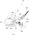
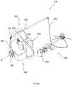
- FIGS. 1 and 2 illustrate an exemplary back-mounted power tool system 100.
- FIG. 1 illustrates a perspective view of system 100
- FIG. 2 illustrates an exploded perspective view of system 100.
- system 100 includes a backpack apparatus 200, a connecting member 300, a power tool 400, and a battery package 500.
- Backpack apparatus 200 may be mounted to a user of system 100 to allow the weight of one or more parts of system 100 to be carried by the user when operating system 100.
- battery package 500 is coupled to backpack apparatus 200, whose weight is transferred to backpack apparatus 200, and then spread over the shoulders, back, and/or waist of the user when backpack apparatus 200 is mounted.
- Power tool 400 may be any suitable type of hand-held or portable power tool or machine. Power tool 400 may need to be flexibly operated by the user, and/or may be operated while the user moves around.
- the mounting of backpack apparatus 200 on the shoulders, back, and/or waist of the user may reduce fatigue of the user when using system 100 for long lengths of time, increase the flexibility and/or efficiency for using power tool 400, and improve user experience.
- Such mountable design may also allow the weight of battery package 500 to be augmented to increase the power and/or voltage supplied to power tool 400 without causing substantial fatigue and/or inconvenience for the user, and thus may improve the efficiency and/or flexibility for operating power tool 400.
- System 100 may include more than one battery packages 500 to supply power to power tool 400.
- battery package 500 may be disposable after one or more uses.
- battery package 500 may be rechargeable and may be used for a plurality of times.
- battery package 500 and/or its battery cells may be used for other power tool systems as well.
- Parameters of battery package 500 such as the weight, number of battery cells, and/or voltage, may be designed such that the power tool 400 may be operated over a predetermined period of time before battery package 500 is fully discharged. Additionally or alternatively, one or more of these parameters may be determined such that the output voltage of battery package 500 may be equal to or above a target level or a predetermined threshold.
- the weight of battery package 500 or the total weight of multiple battery packages 500 may constitute various percentage of the weight of power tool 400, such as ranging from about 30% to about 35%, from about 35% to about 40%, from about 40% to about 45%, from about 45% to about 50%, from about 50% to about 55%, from about 55% to about 60%, from about 60% to about 65%, from about 65% to about 70%, from about 70% to about 75%, from about 75% to about 80%, from about 80% to about 85%, from about 85% to about 90%, from about 90% to about 95%, from about 95% to about 100%, from about 30% to about 40%, from about 40% to about 50%, from about 50% to about 60%, from about 60% to about 70%, from about 70% to about 80%, from about 80% to about 90%, from about 90% to about 100%, from about 100% to about 110%, from about 110% to about 120%, from about 120% to about 130%, from about 130% to about 140%, from about 140% to about 150%, from about 30% to about 50%, from about 50%
- the weight of battery package 500 or the total weight of multiple battery packages 500 may vary depending on the user's weight-load capacity and convenience, such as ranging from about 0.5 kg to about 1 kg, from about 1 kg to about 1.5 kg, from about 1.5 kg to about 2 kg, from about 2 kg to about 2.5 kg, from about 2.5 kg to about 3 kg, from about 3 kg to about 3.5 kg, from about 1 kg to about 2 kg, from about 2 kg to about 3 kg, etc.
- the output voltage of battery package 500 may vary also, such as ranging from about 10 V to about 30 V, from about 30 V to about 50 V, from about 50 V to about 70 V, from about 70 V to about 90 V, from about 90 V to about 130 V, or from about 50 V to about 130 V.
- backpack apparatus 200 includes a backpack harness 210 and a body 220.
- Backpack harness 210 may include one or more shoulder straps 212 and/or at least one waist belt 214 for mounting backpack apparatus 200 onto the user's body, e.g., one or both shoulders, back, and/or waist.
- Shoulder straps 212 may each have one end connected to waist belt 214.
- backpack apparatus 200 may be mounted on one shoulder of the user and/or may be mounted diagonally over a user's body.
- Body 220 of backpack apparatus 200 includes a frame 230, a connector 240 to couple battery package 500 to backpack apparatus 200, and/or a base member 250.
- Frame 230 has a surface that at least partially contacts the back of the user and another surface having connector 240 attached thereto. Increasing the area for the surface of frame 230 contacting the back of the user may increase the support and comfort for the user to wear backpack apparatus 200.
- Frame 230 includes connecting structures that connect to shoulder straps 212 and waist belts 214 of backpack harness 210, such as fixtures, clamps, and holes.
- Connector 240 may be removably or fixedly attached to frame 230.
- Base member 250 is located below connector 240 and is attached to frame 230 on the surface that is not in contact with the user.
- Base member 250 includes a connecting portion 260 to connect to connecting member 300.
- Frame 230, shoulder straps 212, and waist belt 214 may have ergonomic shapes, sizes, structures, and components to reduce strain and improve the comfort for the user to carry backpack apparatus 200 for an extended period of time.
- frame 230, shoulder straps 212, and waist belt 214 may be made of breathable, light weight, and/or flexible materials, and/or may have paddings on the surface facing or contacting the user.
- the paddings may include a compliant and/or resilient material, such as foam or sponge.
- the paddings may reduce the pressure caused by backpack apparatus 200, e.g., frame 230, on the back and/or shoulders of the user.
- Shoulder straps 212 and waist belt 214 may have adjustable structures installed thereon, such as buckles, clasps, slips, clamps, nonslip fasteners, or hooks to adjust their lengths and fitting around the user.
- connecting member 300 connects backpack apparatus 200 to power tool 400.
- connecting member 300 has a fitting member 310 that interlocks or forms a complementary fit with connecting portion 260 of base member 250.
- connecting member 300 has a power tool connector 320 that connects to power tool 400.
- power tool connector 320 is a clamp that fastens a part 420 of the body of power tool 400.
- Connecting member 300 may support the weight of power tool 400, and may transfer the weight of power tool 400 to backpack apparatus 200 when mounted on the user. Connecting member 300 may also transfer a reaction force received from the power tool to the backpack apparatus when the apparatus is mounted on the user to operate.
- connecting member 300 may allow at least a part of the weight or reaction force of power tool 400 to be transferred to and spread over the shoulders, back, and/or waist of the user, which may reduce the work of the user's arm for holding power tool 400, and may thus increase the flexibility and/or period of time for operating power tool 400.
- power tool 400 is a hand-held machine that includes a body and a handle 430.
- Handle 430 may be used for carrying, steering, cruising, and/or controlling power tool 400.
- handle 430 may be held by a user to adjust the angle, movement, and/or position of power tool 400.
- Handle 430 may be designed to be suitable or adjustable for left and/or right hand use.
- handle 430 has electronic control circuits and one or more user controls (not shown), such as switches or buttons, to control the operation of power tool 400.
- the control circuits and one or more user controls may have one or more functions, such as turning on or off power tool 400, or boosting the power or acceleration of power tool 400.
- Handle 430 may further include a display, such as an LED display, to show the status and/or operational parameters of power tool 400, such as speed, strength, temperature, etc.
- the display may be connected to the control circuits.
- the display may also show the remaining capacity of battery package 500, for example, in percentage in relation to its initial full capacity.
- a reaction force when power tool 400 operates and thus generates an action force, a reaction force is generated.
- the body of power tool 400 includes a pipe 410.
- Power tool 400 may propel air out of pipe 410.
- Connecting member 300 may transfer the reaction force from the body of power tool 400 to backpack apparatus 200, which may reduce the work and/or increase the flexibility for the user to control and/or hold power tool 400, which may reduce the fatigue, increase the during for the user to operate power tool 400, and improve user experience. More details of the structures and functions of the components of system 100 are described below.
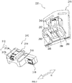
- FIG. 3 illustrates a perspective view of body 220 of backpack apparatus 200.
- a first double-headed arrow shown in FIG. 3 illustrates a vertical direction V
- a second double-headed arrow shown in FIG. 3 illustrates a horizontal direction H.
- direction V is substantially parallel to the direction of the gravitational force
- Direction H is perpendicular to V direction.
- connector 240 is attached to frame 230 on one side and has coupling structures on the opposite side.
- the coupling structures include an elongated protrusion 242, two elongated guiding bars 244, a fastener 246 (such as a lock, a clasp, or a hook), and an electrical terminal 248.
- Protrusion 242 and guiding bars 244 may have any suitable elongated shape, e.g., rectangular or cylindrical.
- Guiding bars 244 are located on two sides of protrusion 242 respectively, and may each be attached to protrusion 242.
- base member 250 of backpack apparatus 200 has a surface 252 facing connector 240.
- Surface 252 may be flat or curved, and at least a part of surface 252 is perpendicular to direction V.
- Protrusion 242 and guiding bars 244 may be attached to surface 252 of base member 250 at the bottom in direction V.
- protrusion 242, guiding bars 244, and base member 250 may be formed as separate parts or an integral part.
- Electrical terminal 248 may be any suitable type of electrical connector.
- electrical terminal 248 has one or more connecting fins or plates made of electrical conducting material, such as copper or aluminum. Electrical terminal 248 forms electrical connection with battery package 500 when battery package 500 is coupled to connector 240.
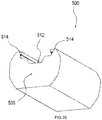
- FIG. 4 illustrates a perspective view of battery package 500.
- Battery package 500 includes a case 510 enclosing or housing one or more battery cells (not shown).
- battery package 500 includes fitting structures complementary to the coupling structures of connector 240.
- case 510 is designed to have fitting structures complementary to the coupling structures of connector 240.
- Case 510 includes an elongated channel 512, two elongated slots 514, a locking slot 516, and an electrical terminal 518.
- Elongated slots 514 are located at two sides of channel 512 respectively, and are each partially enclosed.
- Channel 512 is shaped to at least partially enclose or surround protrusion 242.
- Elongated slots 514 are each shaped to at least partially enclose or surround a corresponding guiding bar 244.
- Locking slot 516 has a shape that allows fastener 246 of connector 240 to fit into.
- fastener 246 has a clasp that interlocks locking slot 516.
- Electrical terminal 518 may have complimentary structures to electrical terminal 248.
- electrical terminal 518 has one or more slots that fit or receive the one or more connecting fins or plates of electrical terminal 248.
- the slots of electrical terminal 518 may have electrical connecting materials forming their bottom or side walls such that electrical connection can be formed between electrical terminal 518 of battery package 500 and electrical terminal 248 of connector 240.
- battery package 500 may be coupled to or removed from connector 240 by moving battery package 500 along connector 240 in direction V, with the fitting structures of case 510 facing the coupling structures of connector 240.
- the fitting structures of case 510 of battery package 500 and the coupling structures of connector 240 may couple battery package 500 to backpack apparatus 200 by sliding protrusion 242 into channel 512, sliding guiding bars 244 into elongated slots 514, sliding connecting fins or plates of electrical terminal 248 into slots of electrical terminal 518, and fitting fastener 246 into locking slot 516.
- fastener 246 includes a clasp (not shown in FIG. 3 ) made of a flexible material and biased towards battery package 500 in direction H.
- the clasp may deflect when battery package 500 is moved along connector 240 until it meets and fits into locking slot 516 to lock battery package in position in direction V and/or direction H.
- fastener 246 may have a flexible member (not shown) rotatably connected to body 220 of backpack apparatus 200.
- the flexible member of fastener 246 may be protruded from body 220, and may clasp, lock, and/or fit into locking slot 516 when fastener 246 is rotated to a predetermined position.
- Fastener 246 is unlocked or released from locking slot 516 when the flexible member of fastener 246 is rotated to another position where the flexible member is retracted into body 220.
- Fastener 246 may be controlled by the user and at least be partially accessible to the user of power tool system 100. Thus, the user may lock or unlock battery package 500 from backpack apparatus 200 by interlocking or unlocking fastener 246 and locking slot 516.
- the bottom side of battery package 500 along direction V is supported by surface 252 of base member 250.
- the weight of battery package 500 is received by base member 250, which is connected to frame 230 of backpack apparatus 200.
- the weight of battery package 500 is then transferred to frame 230, from which transferred to backpack harness 210, and is then received and carried by the user on the shoulders, back, and/or waist.
- backpack apparatus 200 may have a plurality of connectors 240 that can receive a number of battery packages 500.
- base member 250 may support at least a number of the battery packages 500 coupled to backpack apparatus 200, and may transfer the weight of the coupled battery packages 500 to backpack harness 210.
- backpack apparatus 200 further includes an ejecting apparatus 270 that ejects and/or releases battery package 500 from backpack apparatus 200 when fastener 246 and locking slot 516 are unlocked. Ejecting apparatus 270 may reduce the effort for removing battery package 500 from backpack apparatus 200, e.g., connector 240.
- ejecting apparatus 270 is installed in base member 250.
- ejecting apparatus 270 includes two levers 272 and 274 and two bias elements 254 and 256.
- each lever may have a protruding element extending above surface 252.
- lever 272 has a protruding element 276 extended above surface 252
- lever 274 has a protruding element 278 extended above surface 252.
- each level may connect to or be in contact to a corresponding bias element, such as a spring.
- Bias elements 254 and 256 may be attached to a bottom side of surface 252.
- bias elements 254 and 256 are attached to a bottom side of surface 252 along direction V.
- a left end of lever 272 is in contact with bias element 254 and a right end of lever 274 is in contact with bias element 256.
- Protruding elements 276 and 278 are located near the center of the bottom of battery package 500 when installed.
- Bias elements 254 and 256 are located on either the right or left side of base member 250 below surface 252.
- case 510 of battery package of 500 may further include a recess 517 that at least partially receives protruding elements 276 and 278 when battery package 500 is coupled to connector 240.
- Exemplary embodiments of the working mechanism of ejecting apparatus 270 are described herein, in view of FIGS. 3 through 5 .
- the bottom surface of battery package 500 may rest upon surface 252.
- Fastener 246 and locking slot 516 may then lock battery package 500 in position along direction V.
- the weight of battery package 500 and/or the locking of battery package 500 along direction V apply a pressure on protruding elements 276 and 278 such that protruding elements 276 and 278 are pressed to be below or flat with surface 252.
- This causes the left or right end of levers 272 and 274 that is connected to or in contact with bias element 254 or bias element 256 to be raised because of the leverage applied by lever 272 or lever 274.
- Bias elements 254 and 256 are then deformed, e.g., compressed, by the raised left or right end of levers 272 and 274, and thus each apply a pressure to the corresponding lever. But because the position of battery package 500 is locked by fastener 246 and locking slot 516, bias elements 254 and 256 remain deformed and store some amounts of elastic potential energy, and protruding elements 276 and 278 remain below or flat with surface 252.
- protruding elements 276 and 278 When battery package 500 is to be removed from backpack apparatus 200, fastener 246 and locking slot 516 are unlocked. Because the pressure on protruding elements 276 and 278 is reduced when fastener 246 and locking slot 516 unlock, bias elements 254 and 256 then unload the amounts of stored elastic potential energy and each apply a pressure to push levers 272 and 274 respectively. The left end of lever 272 and the right end of lever 274 are then lowered, causing protruding elements 276 and 278 to be elevated because of the leverage applied by levers 272 and 274. The elevated protruding elements 276 and 278 then eject battery package 500 from the bottom to the top of connector 240.
- the ejection of battery package 500 may be performed with a speed and/or in a short time.
- the amounts of elastic potential energy stored in bias elements 254 and 256 may allow battery package 500 to be ejected over a certain distance by at least partially sliding over connector 240.
- ejecting apparatus 270 facilitates the removal of battery package 500 from connector 240 by reducing the effort of the user to decouple, remove, and/or slide battery package 500 away from connector 240.
- FIG. 6 illustrates a perspective view of connecting member 300 of system 100.
- Connecting member 300 may be removably or fixedly connected to backpack apparatus 200.
- connecting member 300 includes fitting member 310 to couple to backpack apparatus 200 and power tool connector 320 to couple to power tool 400.
- Connecting member 300 further includes a first arm 330 and a second arm 340 that are rotatably connected.
- an end 332 of first arm 330 is rotatably coupled to or joined with an end 342 of second arm 340.
- the other end of first arm 330 connects to power tool connector 320, and the other end of second arm 340 connects to fitting member 310.
- power tool connector 320 includes a ring shaped clamp assembled with two half members 322 and 324.
- Half members 322 and 324 may be partially or completely separated, and may be assembled into one integrated part.
- Half members 322 and 324 may be separated or assembled via any suitable mechanical structure that allows for quick assembly and release, e.g., structures that use friction fit, press fit, twist fit, or snap fit to assemble half members 322 and 324.
- part 420 of the body of power tool 400 may be placed between at least partially separated half members 322 and 324, which then are closed and assembled into an integrated part, e.g., the clamp.
- Half members 322 and 324 of the assembled clamp may tightly hold power tool 400.
- power tool connector 320 may include adjustment structures to adjust the tightness of holding or clamping power tool 400.
- power tool connector 320 may include surfaces made of materials that increase the friction between half members 322 and 324 and power tool 400.
- the connection between power tool connector 320 and power tool 400 may be substantially similar to that between fitting member 310 and base member 250 of backpack apparatus 200, which is described further below with respect to FIG. 7 .
- first arm 330 has a compliant member 334 between a fixture of first arm 330 and power tool connector 320 to damp a force generated during the operation of power tool 400, such as a reaction force or vibration force between power tool 400 and backpack apparatus 200.
- a reaction force caused by an action force generated by the operation of power tool 400 may be damped or retarded and then received by first arm 330, and then transferred to backpack apparatus 200 via connecting member 300.
- Compliant member 334 may be a spring that when applied a force deforms and stores an elastic potential energy caused by the deformation. The spring may reform and release the elastic potential energy when the force applied decreases and/or no longer exists.
- compliant member 334 may damp or retard the interaction between power tool 400 and connecting member 300, between power tool 400 and backpack apparatus 200, and/or between power tool 400 and the user's hand holding handle 430.
- power tool 400 may include more than one compliant members 334 between power tool 400 and connecting member 300.
- Connecting member 300 allows both a pulling force and a pushing force to be transferred between power tool 400 and backpack apparatus 200.
- connecting member 300 may transfer a pushing force, e.g., a reaction force received by first arm 330 from power tool 400, to backpack apparatus 200.
- compliant member 334 may be elastically compressed, and may transfer the reaction force to first arm 330.
- First arm 330 may transfer the reaction force to second arm 340, which may transfer the reaction force to fitting member 310.
- Fitting member 310 then may transfer the reaction force to base member 250 of backpack apparatus 200.
- connecting member 300 may transfer a pulling force, e.g., the weight of power tool 400, to backpack apparatus 200.
- compliant member 334 may be elastically elongated, and may transfer the gravitational force by pulling compliant member 334, which transfers the pulling force to first arm 330.
- First arm 330 may transfer the pulling force to second arm 340, which may transfer the pulling force to fitting member 310.
- Fitting member 310 may then transfer the pulling force to base member 250 of backpack apparatus 200.
- the force transferred to base member 250 is then transferred to backpack harness 210 and applied to the shoulders, back, and/or waist of the user.
- the above-described transferring and/or damping or retarding of one or more types of force by connecting member 300 may reduce the user's work and/or fatigue for operating power tool 400, and increase the convenience, flexibility, comfort, and/or control for operating power tool 400.
- FIG. 7 illustrates perspective views of fitting member 310 of connecting member 300 and body 220 of backpack apparatus 200.
- fitting member 310 may include structural components that are complementary to connecting portion 260 of base member 250 of backpack apparatus 200 such that connecting member 300 may be removably or fixedly coupled to backpack apparatus 200.
- fitting member 310 includes one or more elongated spines 314, one or more guiding slots 316, and a locking structure 312.
- Locking structure 312 locks fitting member 310 to connecting portion 260 in position when fitting member 310 is fitted into connecting portion 260 of base member 250 of backpack apparatus 200.
- Connecting portion 260 includes one or more receiving slots 264, one or more guiding ribs 266, and a locking slot 262.
- fitting member 310 may be aligned with base member 250 and/or be fit into connecting portion 260, e.g., by a slidable fitting.
- fitting member 310 As fitting member 310 is slid into connecting portion 260, elongated spines 314 are received by receiving slots 264 and guiding ribs 266 are received by guiding slots 316.
- locking structure 312 interlocks locking slot 262, and thus locks the position of fitting member 310, e.g., in direction H.
- locking structure 312 of fitting member 310 includes two parts, a hook 312a and a release 312b.
- Hook 312a may stick into locking slot 262 as fitting member 310 moves into connecting portion 260 along direction H.
- fitting member 310 and backpack apparatus 200 become one integrated part.
- Hook 312a may be at least partially retractable into fitting member 310.
- release 312b may be adjusted by, such as sliding, rotating, or pressing, such that hook 312a is retracted from locking slot 262 and/or at least partially into fitting member 310. Then, fitting member 310 may be unlocked and may be removed from connecting portion 260.
- connecting portion 260 may have a locking structure similar to structure 312 and fitting member 310 may have a locking slot similar to slot 262.
- fitting member 310 and connecting portion 260 of base member 250 allows the two parts to become an integrated part, in which fitting member 310 is a supporting platform for backpack apparatus 200.
- This connection facilitates the transfer of force from connecting member 300 to backpack apparatus 200 and thus improves user experience.
- fitting member 310 and/or connecting member 300 bearing the weight of battery package 500 and/or other types of force may be at about the height of the waist of the user. This height may be suitable for transferring the weight and/or force to frame 230 and then to backpack harness 210 without substantially compromising the comfort of the user.
- fitting member 310 may allow the length of backpack apparatus 200, e.g., frame 230, to be shorter along direction V, and improves the comfort of wearing backpack apparatus 200 by the user.
- fitting member 310 may provide more comfort and/or reduce fatigue for the user by improving the ergonomics of system 100.
- first arm 330 and second arm 340 of connecting member 300 in FIG. 6 are rotatably connected.
- the rotational connection between first arm 330 and second arm 340 are further described below with reference to FIGS. 6 , 8 , and 9 .
- FIG. 6 illustrates a first axis "E" and a second axis "F.”
- Axis E is perpendicular to Axis F.
- FIG. 8 illustrates a perspective view of a cross-section of connecting member 300 with some parts illustrated in a partially exploded view.
- FIG. 9 illustrates a cross-section of connecting member 300.
- end 332 of first arm 330 rotatably connects to end 342 of second arm 340 such that first arm 330 may rotate relative to second arm 340 around or about the F axis, and vice versa.
- end 342 is a half shell having an opening facing up.
- End 342 has a connecting pillar 344 inside of the shell and extending above the opening.
- a bearing 370 e.g., a ball bearing, is installed on a top part of connecting pillar 344.
- end 332 of first arm 330 is a half shell with a hole or recess to receive bearing 370.
- End 332 of first arm 330 is placed on top of end 342 of second arm 340 such that first arm 330 can rotate about pillar 344 of second arm 340.
- Bearing 370 may reduce the rotational friction between end 332 of first arm 330 and end 342 of second arm 340.
- end 342 of second arm 340 may be placed on top of end 332 of first arm 330, which may have pillar 344 and bearing 370 installed thereupon.
- both ends 342 and 332 are half shells, when they are closed and joined, a cavity is formed by the closing and/or joining the half shells. As shown in FIGS. 8 and 9 , this cavity may be used for laying a power cord 360 to conduct electricity, e.g., current, from battery package 500 to power tool 400.
- Placing power cord 360 inside first arm 330 and second arm 340 may reduce the effect of external wires on the operation of power tool 400 and improves user experience.
- the placement of power cord 360 inside connecting member 300 may at least reduce obstruction and/or restriction of the movement of the user's arm and/or power tool 400 that may be caused by power cord 360 laying outside of connecting member 300. More details about the electrical connection between battery package 500 and power tool 400 are further described below.
- second arm 340 is rotatably connected to a fitting portion 318 of fitting member 310.
- Fitting portion 318 may include a cavity to at least partially receive second arm 340.
- Second arm 340 may be removably and/or frictionally fit into the cavity of fitting portion 318.
- connecting member 300 further includes an reinforcement arm 350 fixedly or removably installed in the cavity of fitting portion 318.
- Reinforcement arm 350 may have any shape that can fit into second arm 340 via a suitable mechanical means, e.g., friction fit, press fit, twist fit, snap fit, overmolding or molding, thermal bonding, adhesive bonding, and/or welding.
- reinforcement arm 350 may have a tapered tubular shape substantially complementary to the inner perimeters of at least a part of second arm 340 such that reinforcement arm 350 may be at least partially inserted into second arm 340.
- second arm 340 is supported by reinforcement arm 350 from the inside and by fitting portion 318 on the outside.
- the fitting between second arm 340 and reinforcement arm 350, and/or the fitting between second arm 340 and fitting portion 318 allow second arm 340 to be rotatable relative to reinforcement arm 350 and/or fitting portion 318 around or about axis E.
- first arm 330 and second arm 340 and between second arm 340 and fitting member 310 allow the user to rotate power tool 400 around or about axes E and F as needed.
- the rotational angle of both first arm 330 and second arm 340 may range up to about 360° such that power tool 400 may be operated or oriented towards any direction over a spherical space.
- power tool 400 may not need to operate or orient over a spherical space, and may be designed to rotate within predetermined ranges to improve safety of the user during operation and/or control of power tool 400.
- the rotational angle of first arm 330 relative to second arm 340 may range from about 60° to about 90°, from about 90° to about 120°, from about 120° to about 150°, from about 150° to about 180°, from about 60° to about 120°, from about 60° to about 150°, from about 90° to about 150°, or from about 90° to about 180°.
- the rotational angle of second arm 340 relative to fitting member 310 may range from about 30° to about 60°, from about 60° to about 90°, from about 90° to about 120°, from about 120° to about 150°, from about 150° to about 180°, from about 40° to about 90°, from about 40° to about 120°, from about 60° to about 120°, or from about 60° to about 180°.
- the rotation of power tool 400 with first arm 330 and/or second arm 340 increases the flexibility and dynamic range for the user to operate power tool 400. For instance, when the user stays at one location, the rotation of power tool 400 executed by the user allows the user to use power tool 400 across a certain space, e.g., a fan-shaped region, around or about axis E and/or axis F. When power tool 400 is a blower, a user may sweep leaves and/or debris of a certain area before moving to a next standing location.
- the rotational connections of connecting member 300 with power tool 400 and backpack apparatus 200 increase the flexibility for operating power tool 400 and/or save the energy for the user operating power tool 400.
- power tool 400 may refer to any suitable power tool that can be powered by a battery and/or held by a user in their hands, such as a blower, a vacuum, a blower vacuum, a mulcher, a trimmer, a chainsaw, a grass cutter, a brush cutter, a tying machine, a drill, a lawn mower, a circular saw, an angle grinder, a sander, reciprocating saws, etc.
- power tool 400 is a blower, such as a leaf blower or a garden blower.
- reference below to power tool 400 may refer to a blower for illustrating exemplary embodiments of system 100.
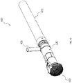
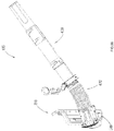
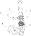
- FIG. 10 illustrates a perspective view of an exemplary power tool 400.
- power tool 400 includes a pipe 410, handle 430, and a protective mesh 440.
- Pipe 410 provides a passage for an air flow generated by an engine or motor in power tool 400.
- Pipe 410 may be formed as one integrated part, such as by injection molding, or may be assembled from a plurality of individual parts.
- pipe 410 has a tubular shape, such as a hollow cylinder.
- Pipe 410 may be made of a plastic material. The plastic material may be light-weight, durable, non-conductive, heat-resistant, and/or stress-resistant.
- the material of pipe 410 may include one of polyvinyl chloride (PVC), polyethylene (PE), polypropylene (PP), and/or carbon fiber (CF).
- PVC polyvinyl chloride
- PE polyethylene
- PP polypropylene
- CF carbon fiber
- the material of pipe 410 may be selected to be suitable for the application of power tool 400.
- power tool 400 may further include part 420 that connect to power tool connector 320 of connecting member 300.
- Handle 430 may be used for carrying, cruising, steering, adjusting, and/or controlling power tool 400.
- handle 430 may be held by the user to adjust the angle, movement, and/or position of pipe 410 such that the air flow ejected from pipe 410 may orient towards a direction at the control of the user.
- Mesh 440 includes a plurality of openings sized to allow air flow to go through but to block objects from entering pipe 410.
- mesh 440 may reduce the potential risks to the safety of the user that may be caused by undesirable objects that may enter, interrupt, and/or damage power tool 400.
- mesh 440 may be removed for a user to inspect the inside of power tool 400, e.g., inside of pipe 410.
- Mesh 440 may be made of a plastic or other material, such as the material of pipe 410, and may be replaceable.
- FIG. 11 illustrates a perspective view of a cross-section of power tool 400.
- FIG. 12 illustrates a cross-section of power tool 400 with mesh 440 detached.
- power tool 400 includes a motor 460 connected to an air-generating device 470 via a motor shaft 464.
- Air-generating device 470 may be a fan or a propeller with one or more blades. The rotation of motor 460 provides the torque, force, and/or moment driving air-generating device 470 via motor shaft 464 to generate an air flow.
- the speed and/or strength of the generated air flow may be determined by the voltage and/or power supplied to motor 460, the shape and size of air-generating device 470, and/or the length and shapes of pipe 410.
- the speed of the air flow generated by power tool 400 may range from about 40 mph to about 80 mph, from about 80 mph to about 120 mph, from about 120 mph to about 160 mph, from about 40 mph to about 130 mph, or from about 50 mph to about 120 mph.
- pipe 410 has an airway 412 with an air inlet 414 and an air outlet 416.
- Airway 412 provides a passage for the air flow generated by air-generating device 470 and motor 460.
- power tool 400 is a blower
- the air flow moves from inlet 414 to outlet 416.
- power tool 400 is a vacuum
- the air flow moves from outlet 416 to inlet 414.
- the length of pipe 410 and/or the distance between inlet 414 and outlet 416 may be predetermined, and may not change as power tool 400 moves or operates.
- the length of pipe 410 and/or the distance between inlet 414 and outlet 416 may be adjustable.
- the distance between inlet 414 and outlet 416 may be adjusted by the user to be suitable for a particular application and/or to increase the comfort or ease for operating power tool 400.
- the sizes and shapes of airway 412, inlet 414, and/or outlet 416 may affect the direction, the speed, and/or strength of the generated air flow, and may be designed to generate an air flow suitable for a particular application, e.g., sweeping debris and/or leaves in a private or public area.
- Some conventional blowers or vacuums have their motors and/or air inlets mounted on the pack of the user and use soft flexible tubes to connect the air inlet with a pipe that guides the air flow. In those conventional blowers or vacuums, a user cannot see the motors and/or air inlets mounted on the back.
- the location of inlet 414 of power tool 400 allows the user to observe power tool 400, inlet 414, and/or outlet 416 while operating power tool 400.
- the design of system 100 increases the safety of using power tool 400 by allowing the user to observe and avoid inlet 414 from hazardous locations.
- system 100 does not require using a flexible tube to connect inlet 414 to pipe 410, and thus reduces or eliminates the problems that may result from the damage of such flexible tube, and increases the life of power tool 400.
- the distance between inlet 414 and outlet 416 of pipe 410 may be adjusted, e.g., shortened or extended, to a suitable length.
- Pipe 410 may be fixed at the adjusted suitable length or at a predetermined length during the operation of power tool 400, which may increase the consistency and/or steadiness of the air flow in pipe 410. The increased consistency and/or steadiness of the air flow in pipe 410 may also increase the life of power tool 400.
- handle 430 is connected to the outside surface of pipe 410. Handle 430 may be placed at a location convenient for the user to execute movement and/or control of power tool 400, e.g., within an arm's length of the user. In some embodiments, handle 430 is located above the center of gravity of power tool 400 to reduce the effect of the weight of power tool 400 on the movement and/or control of handle 430. In other embodiments, handle 430 is adjustable by the user to be at a convenient and/or suitable position to reduce fatigue, increase flexibility, and improves user experience for the user operating power tool 400. In some embodiments, handle 430 is located between inlet 414 and outlet 416.
- the distance between the handle 430 and inlet 414 and/or the distance between handle 430 and outlet 416 may be adjustable or fixed. In other instances, the distance between the handle 430 and inlet 414 and/or the distance between handle 430 and outlet 416 may be adjusted along with the adjustment of the distance between inlet 414 and outlet 416.
- motor 460 is a brushless motor, such as a brushless motor in an external-rotor configuration.
- Brushless motors do not have mechanical brush contacts with the commutator, i.e., the moving part of a rotary electrical switch. This may reduce the probability of discharging electrons and/or generating electric sparks, e.g., by friction.
- using a brushless motor 460 may increase the safety of using power tool 400.
- air-generating device 470 is an axial fan or an axial propeller having a plurality of blades that can spin around an axis of rotation.
- the blades of air-generating device 470 may be any suitable shape, such as aerofoil, sickle, or paddle, and may have variable or uniform pitch.
- An axial fan or an axial propeller as air-generating device 470 is more suitable for generating an air flow in pipe 410 to achieve a greater amount of air volume, speed, and/or strength.
- the axis of rotation of air-generating device 470 is illustrated as axis "A".
- axis A is the central axis of pipe 410 and/or airway 412.
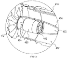
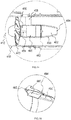
- FIG. 13 illustrates a magnified perspective view of a part of power tool 400.
- FIG. 14 illustrates a magnified view of a cross-section of the part of FIG. 13 .
- power tool 400 has a motor housing 450 having motor 460 installed therein.
- Motor housing 450 is located in airway 412 such that the center of mass and/or the axis of rotation of motor 460 is aligned with axis A.
- motor housing 450 is an integral part of pipe 410.
- motor housing 450 is a separate part installed in airway 412 of pipe 410 via a suitable connective structure 458.
- connective structure 458 between motor housing 450 and pipe 410 may provide a passage for electrical connections to motor 460, such as electrical wires connecting motor 460 to battery package 500 or other electronic circuits or components.
- the structure of motor housing 450 and/or connective structure 458 between motor housing 450 and pipe 410 may allow force, e.g., force generated inside pipe 410, to be transferred to the walls and/or outside surface of pipe 410.
- the walls and/or surface of pipe 410 may then transfer the force to backpack apparatus 200 via connecting member 300.
- the rotation of air-generating device 470 may generate a reaction force when propelling an air flow along axis A.
- the reaction force is transferred to motor 460 via motor shaft 464.
- Motor shaft 464 then transfers the reaction force to motor housing 450 and/or connective structure 458, which then transfers the reaction force to pipe 410.
- Pipe 410 than transfers the reaction force to backpack apparatus 200 via connecting member 300.
- Such transferring of a reaction force generated during the creating of the air flow to backpack apparatus 200 reduces the force transferred to handle 430 and the user, and thus increases comfort, reduces fatigue, and increases the period of time for the user to operate power tool 400.
- the weight of motor 460 may constitute a large portion of the total weight of power tool 400.
- the center of mass or center of gravity of power tool 400 may be adjacent or close to motor 460 and/or motor housing 450.
- motor housing 450 may be installed at a location near handle 430 in airway 412 to reduce the effect of the weight of power tool 400 on the movement and/or control of handle 430.
- the center of gravity of power tool 400, point "G” is located near motor housing 450 and below handle 430.
- the location of motor 460 and/or motor housing 450 along pipe 410 may be where part 420 is located such that the weight of motor 460 and/or motor housing 450 may be substantially transferred to connecting member 300, and then to backpack apparatus 200, for example, to reduce fatigue of the user.
- power tool 400 includes an internal cooling fan 462 to generate an internal air flow to cool motor 460 and/or other components of power tool 400, such as electronic circuits or controls.
- Fan 462 may be an axial fan. As shown in FIGS. 11-14 , fan 462 is connected to motor 460, e.g., by a shaft, and is powered or driven by motor 460.
- motor housing 450 includes an inner chamber 452, a first opening 454, and a second opening 456.
- Fan 462 is positioned inside motor housing 450.
- the air flow generated by fan 462 may flow from opening 454, into chamber 452, pass through motor 460, taking the heat generated by motor 460, and then exit from opening 456.
- the air flow generated by fan 462 may flow from opening 456, pass through motor 460, taking the heat generated by motor 460, into chamber 452, and then exit from opening 454.
- fan 462 and air-generating device 470 are designed to be located on two opposite sides of motor 460 along axis A.
- the structures and/or rotation of fan 462 are designed to generate an air flow that has an opposite direction from that generated by air-generating device 470.
- at least a portion of the air flow generated by fan 462 and a portion of the air flow generated by air-generating device 470 form a circulating air flow around motor 460.
- the direction of the air flow generated by air-generating device 470 is from inlet 414 to outlet 416. In such instances, the direction of the air flow generated by fan 462 is from opening 454 to opening 456.
- the air flow exiting from opening 456 is then propelled by air-generating device 470 towards outlet 416. Because a pressure difference exists between chamber 452 and airway 412 when fan 462 operates, at least a portion of the air flow propelled by air-generating device 470 towards outlet 416 enters opening 454 and then moves towards opening 456.
- Such circulated air flow surrounding motor 460 and/or other components inside motor housing 450 may increase dissipation of the heat generated by motor 460. This may increase the life of power tool 400, and may increase the safety for using power tool 400.
- power tool 400 is a vacuum
- the circulated air flow surrounding motor 460 is in the opposite direction from that described above.
- power tool 400 includes at least one electronic circuit board 480.
- Circuit board 480 is electrically connected to at least motor 460, user controls and/or control circuits in handle 430, and/or battery package 500 of backpack apparatus 200.
- circuit board 480 may control the operation of motor 460.
- circuit board 480 is installed between inlet 414 and handle 430.
- circuit board 480 is installed adjacent inlet 414 such that a portion of the air flow passing through inlet 414 may take away the heat.
- power tool 400 further includes a ventilated chamber 490 having circuit board 480 installed therein. Chamber 490 may allow cooling of circuit board 480 when power tool 400 operates.
- FIG. 15 illustrates a magnified perspective view of circuit board 480 and chamber 490.
- FIG. 16 illustrates a magnified view of a cross-section of the part shown in FIG. 15 .
- chamber 490 is located adjacent to inlet 414 of pipe 410.
- Chamber 490 includes at least one air inlet 492 and at least one air outlet 494.
- Inlet 492 may be located at the edge of inlet 414.
- mesh 440 covers inlet 414 including inlet 492.
- Outlet 494 may be located between inlet 414 and outlet 416, e.g., between inlet 414 and handle 430.
- Circuit board 480 may be installed by any suitable mechanical means inside chamber 490 between inlet 492 and outlet 494.
- circuit board 480 may be installed at a place such that the air flow from inlet 492 to outlet 494 passes by circuit board 480, thereby taking away the heat generated by circuit board 480.
- chamber 490 is separated from airway 412 so that the air flow to pass through chamber 490 does not enter airway 412, and thus is substantially restricted to flow from inlet 492 to outlet 494 to pass by and cool circuit board 480.
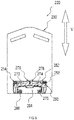
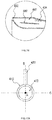
- FIGS. 17A and 17B illustrate exemplary cross-sections of power tool 400 at the location of handle 430.
- the cross-sections shown in FIGS. 17A and 17B are perpendicular to axis A of pipe 410.
- axis B and axis C are shown in FIGS. 17A and 17B .
- Axis B is perpendicular to axis C in the plane of the cross-sections shown in FIGS. 17A and 17B .
- Both axes B and C are perpendicular to axis A.
- axis B is a longitudinal axis of handle 430.
- axis B is a projection of the longitudinal axis of handle 430 in the plane of the cross-sections shown in FIGS. 17A and 17B .
- axis B passes across the cross-section of airway 412. In some instances, axis B passes through the center of the cross-section of airway 412, as shown in FIG. 17A . In other instances, axis B passes across the cross-section of airway 412, but does not pass through the center of the cross-section of airway 412, as shown in FIG. 17B .
- the position of axis B along axis C in the cross-sections shown in FIGS. 17A and 17B may be predetermined or adjustable by the user to increase the comfort and/or convenience for using power tool 400, and/or to reduce fatigue for long periods of operation of power tool 400. In other embodiments, the position of axis B along axis C may be changed to be suitable for particular types of power tool 400.
- the longitudinal axis of handle 430 is at an angle to axis A.
- the angle between the longitudinal axis of handle 430 and axis A may range from about 20° to about 40°, from about 40° to about 60°, from about 60° to about 80°, from about 45° to about 80°, from about 45° to about 90°, from about 30° to about 60°, from about 60° to about 90°, or from about 30° to about 90°.
- the angle between the longitudinal axis of handle 430 and axis A may be designed to increase the comfort, effectiveness, and/or flexibility for the user to control handle 430 and/or power tool 400.
- the angle may be selected to allow the forearm of the user to be approximately parallel to axis A of pipe 410.
- the angle may be adjustable based on the need of the user and/or the type of power tool 400.
- FIG. 18 illustrates a magnified view of a cross-section of a part of handle 430.
- handle 430 includes a fixing pillar 432 and a damping element 434.
- Fixing pillar 432 is fixedly connected to the body of power tool 400, e.g., pipe 410 of power tool 400.
- Damping element 434 may be a compressible and resilient part, such as a gasket. Damping element 434 may be made a polymer material, such as rubber or polyethylene.
- damping element 434 surrounds pillar 432 and damps the force transferred between power tool 400 and handle 430, such as the reaction force transferred from pipe 410 to handle 430 during the operation of power tool 400. Damping element 434 may reduce the fatigue and/or increase the flexibility for the user to operate and control power tool 400, and thus may increase the period of operation and/or may improve user experience.
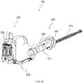
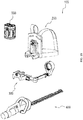
- FIGS. 19 and 20 illustrate an exemplary back-mounted power tool system 100.
- FIG. 19 illustrates a perspective view of system 100.
- FIG. 20 illustrates an exploded perspective view of system 100.
- power tool 400 is a hedge trimmer.
- Power tool 400 includes a cutting device 410, a body 421, and a handle 430.
- cutting device 410 has an elongated shape and a plurality of blades 410 spaced along its length.
- Cutting device 410 may be removable and replaceable.
- Body 421 houses a motor that connects to cutting device 410 via any suitable transmission shaft to drive the blades to move back and forward along the length of cutting device 410.
- Handle 430 may have one or more features as described above.
- power tool 400 may include a front handle 438 that can be used for holding and/or controlling power tool 400.
- the use of both handles 430 and 438 may increase the comfort, control, flexibility, convenience, and/or safety for the user while using power tool 400 to trim or prune hedges or trees in any direction.
- connecting member 300 connects power tool 400 to backpack apparatus 200.
- Power tool connector 320 may connect to any suitable part of power tool 400.
- power tool connector 320 clamps power tool 400 at a location near the center of gravity of power tool 400.
- power tool connector 320 clamps at a location between one end of power tool 400 and handle 430.
- Connecting member 300 may transfer a force from power tool 400 to backpack apparatus 200. For example, when power tool 400 trims or cuts some trees or objects, movement of cutting device 410 generates an action force. Cutting device 410 and body 421 of power tool 400 thus receives a reaction force from the trees or objects.
- Connecting member 300 may transfer the received reaction force from power tool 400 to backpack apparatus 200, which may reduce the work of the user for controlling and/or holding power tool 400, which can improve user experience, reduce fatigue of the user's arms, and increase the time period for the user to operate power tool 400.
- FIG. 21 illustrates a perspective view of an exemplary back-mounted power tool system 100.
- FIG. 22 illustrates a perspective view of embodiments of system 100 of FIG. 21 .
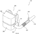
- system 100 includes backpack apparatus 200, power tool 400, and power cord 360.
- Backpack apparatus 200 has two connectors 240 that may couple two battery packages 500. The coupling of battery package 500 to connector 240 may be substantially the same as described above.
- backpack apparatus 200 further includes at least one chamber 280. Chamber 280 is enclosed by a casing. Chamber 280 may include electronic circuits and electronic components (not shown) that control and/or regulate the power supply from battery package 500 to backpack apparatus 200, and then to power tool 400.
- the casing of chamber 280 may enclose base member 250 (shown in FIG. 2 ) of backpack apparatus 200.
- backpack apparatus 200 serves as a power supply to power tool 400 or a power transfer/adapter unit by conducting power supply from battery package 500 to power tool 400.
- electrical terminal 248 (shown in FIG. 3 ) of connector 240 serves as a power inlet to receive power supply and/or current from battery package 500.
- backpack apparatus 200 includes a power outlet 282 to transfer power and/or current supplied by battery package 500 to power tool 400 via power cord 360, for example.
- the electronic circuits contained in chamber 280 provide a passage for the transfer of the power and/or current.
- an electrical wire may connect electrical terminal 248 to outlet 282 to transfer the power and/or current of battery package 500 to power tool 400.
- outlet 282 is placed in the casing of chamber 280.
- the electronic circuits contained in chamber 280 may control the transfer of power and/or current supplied by battery package 500 to power tool 400, such as by turning on or off of the conduction of current, regulating the magnitude of the output current or voltage of outlet 282, and/or adapting the output current or voltage of outlet 282 to a particular power tool 400.
- the power for the electronic circuits contained in chamber 280 may be supplied by battery package 500, or may be supplied by a battery included in chamber 280.
- the power supply to backpack apparatus 200 may come from any battery package 500 coupled to connector 240.
- backpack apparatus 200 includes built-in battery cells and an AC power inlet.
- the built-in battery cells may be charged and thus stores electrical energy by receiving AC power supply via the AC power inlet.
- the built-in battery cells may be contained in chamber 280.
- the built-in battery cells loaded with electrical energy may supply power and/or current to the electronic circuits contained in chamber 280, to battery package 500 via electrical terminal 248, and/or to power tool 400 via outlet 282.
- the power received by the AC power inlet of backpack apparatus 200 may be used to charge battery package 500 via electrical terminal 248, and/or to supply power and/or current to power tool 400 via outlet 282.
- backpack apparatus 200 includes cables and connectors to electrically connect the AC power inlet to an AC power supply. The cables and connectors may be placed in chamber 280 when not in use.
- power tool 400 includes a battery connector 600.
- Battery connector 600 may include a power inlet 610.
- Power cord 360 may connect power outlet 282 to power inlet 610 to supply power and/or current to power tool 400, e.g., a motor of a blower or trimmer.
- power cord 360 has a first connector 362 at one end that is suitable for connecting to power outlet 282.
- Power cord 360 has a second connector 364 at the other end that is suitable for connecting to power inlet 610.
- the connectors of power outlet 282, power inlet 610, and connectors 362 and 364 may be any suitable type of electrical connectors.
- FIG. 23 illustrates another perspective view of system 100.
- battery package 500 includes a power outlet 520.
- electrical power, energy, and/or current may be directly transferred from battery package 500 to power tool 400.
- first connector 362 of power cord 360 may connect to power outlet 520 of battery package 500
- second connector 364 of power cord 360 may connect to power inlet 610 of power tool 400.
- backpack apparatus 200 serves to provide support for battery package 500 and reduces the effect of the weight of battery package 500 on the operation of power tool 400.
- FIG. 24 illustrates perspective views of power tool 400 and battery package 500 of system 100.
- FIG. 25 illustrates a perspective view of battery package 500.
- FIG. 26 illustrates a magnified perspective view of battery connector 600 of power tool 400.
- battery connector 600 of power tool 400 includes connector 240 that may couple battery package 500.
- the coupling structures of connector 240 of battery connector 600 and the fitting structures of battery package 500 are substantially similar to those in the above-described embodiments.
- an end surface 530 of battery package 500 may be stopped by a stopping wall 620 of battery connector 600.
- fastener 246 of connector 240 and locking slot 516 of battery package 500 may interlock, which then locks the position of battery package 500 and prevents battery package 500 from decoupling from battery connector 600.
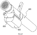
- FIG. 27 illustrates a perspective view of power tool 400 having battery connector 600 coupled to battery package 500.
- the coupling of battery package 500 to battery connector 600 allows battery package 500 to directly supply electrical energy, power, and/or current to the motor and/or the electronic circuits of power tool 400.
- power tool 400 and battery package 500 become an integrated part, and may be operated separately from backpack apparatus 200.
- system 100 may include more than one power tools 400.
- FIG. 28 illustrates a perspective view of an exemplary system 100 including two power tools 400, herein referred to as power tools 400a and 400b.
- Power tools 400a and 400b may be any type of power tool 400 described above.
- power tool 400a is a blower and power tool 400b is a hedge trimmer.
- system 100 may include more than one battery packages 500 to supply power to each power tool.
- system 100 includes three battery packages, herein referred to as battery packages 500a, 500b, and 500c.
- Power tools 400a and 400b may each include a battery connector 600 to couple one of the battery packages.
- Backpack apparatus 200 may have one or more connectors 240.
- the connectors 240 of backpack apparatus 200 and battery connectors 600 are substantially the same. Thus, each battery package may be coupled to any of the connectors 240 of system 100.
- the interchangeability of the battery packages allows various types of power tools having battery connector 600 to be used in system 100, increasing the versatility and compatibility of system 100.
- battery packages 500a and 500b are coupled to battery connectors 600 of power tools 400a and 400b respectively.
- the coupling of battery packages 500a and 500b to power tools 400a and 400b allows the battery packages to directly supply power to the power tools.
- Battery package 500c may be coupled to backpack apparatus 200 to be used as a backup when either battery package 500a or 500b is partially or fully discharged.
- the discharged battery package 500a or 500b may be decoupled from the corresponding power tool, and may be coupled to connector 240 of backpack apparatus 200.
- the discharged battery package 500a or 500b may be recharged when coupled to backpack apparatus 200.
- the use of backpack battery package 500c and/or recharging of the discharged battery packages may increase the periods of time for operating power tools 400a and 400b.
- backpack apparatus 200 includes two power outlets 282, herein referred to as outlets 282a and 282b.
- System 100 includes two power cords 360, herein referred to as power cords 360a and 360b.
- power cords 360a and 360b may connect outlets 282a and 282b to power inlets 610 of power tools 400a and 400b respectively.
- backpack apparatus 200 may serves as the power supply or a power transfer unit to supply power and/or current to both power tools 400a and 400b.
- power tools 400a and 400b when power tools 400a and 400b are both coupled to battery packages 500a and 500b respectively, or are connected to backpack apparatus 200 via power cords 360a and 360b respectively, power tools 400a and 400b may be used at the same time. For example, a user may use one hand to control power tool 400a and the other hand to control power tool 400b.
- Power tool 400 coupled with battery package 500 may increase the overall weight to be carried with one's hand and arm when operating power tool 400, and thus increases fatigue and/or reduces flexibility of operating power tool 400.
- System 100 shown in FIGS. 21-23 and 28 may further include connecting member 300.
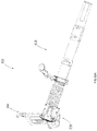
- FIGS. 29 and 30 illustrate perspective views of an exemplary back-mounted power tool system 100.
- System 100 includes backpack apparatus 200, connecting member 300, power tool 400, and power cord 360.
- connecting member 300 may support the weight of power tool 400, and transfer the weight of power tool 400 to backpack apparatus 200 when mounted on the user.
- Connecting member 300 may allow at least a part of the weight of power tool 400 to be spread over the shoulders, back, and/or waist of the user. Additionally or alternatively, connecting member 300 may transfer a reaction force from power tool 400 to backpack apparatus 200, which may reduce the work of the user for controlling and/or holding power tool 400. Connecting member 300 may thus reduce fatigue of the user's arm and hand for holding power tool 400, improve user experience, and/or increase the flexibility and period of time for operating power tool 400.
- connecting member 300 includes a fitting member 310 that removably or fixedly connects to backpack apparatus 200, a power tool connector 320 that removably or fixedly connects to power tool 400, and a first arm 330 rotatably connected to a second arm 340.
- first arm 330 connects to second arm 340 via a hinge 380 such that first arm 330 may rotate around second arm 340 or vice versa.
- Hinge 380 may be designed to limit the rotational angle between first arm 330 and second arm 340.
- first arm 330 may rotate up to an angle ranging from about 100° to about 120°, from about 120° to about 140°, from about 140° to about 160°, or from about 160° to about 180° relative to second arm 340.
- fitting member 310 and power tool connector 320 may be substantially the same as described above.
- fitting member 310 may be inserted into a recess of backpack apparatus 200 and then locked in position such that connecting member 300 and backpack apparatus 200 become one integrated part.
- power tool connector 320 may be inserted into a recess of a fixture of power tool 400 and then locked in position such that connecting member 300, power tool 400, and backpack apparatus 200 become one integrated part.
- power cord 360 may connect backpack apparatus 200 to power tool 400 via outlet 282 or may connect battery package 500 to power tool 400 via outlet 520 (as shown in FIG. 23 ) of battery package 500 similarly as described above.
- backpack apparatus 200 includes a protective cover that encloses battery package 500 and/or connector 240 in a chamber. The protective cover may be removed and/or openable for the user to retrieve or replace battery package 500.
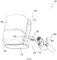
- FIG. 31 illustrates a perspective view of an exemplary back-mounted power tool system 100.
- System 100 may include a protective cover 290 that encloses one or more battery packages 500 and/or connectors 240 in a closed chamber.
- backpack apparatus 200 includes built-in battery cells (not shown).
- the built-in battery cells may be charged via an AC power inlet of backpack apparatus 200 and thus stores electrical energy.
- the built-in battery cells may be contained in the chamber enclosed by cover 290.
- the built-in battery cells may supply electrical power and/or current to electronic circuits contained in backpack apparatus 200, and then to power tool 400.
- the built-in battery cells may supply electrical power and/or current to power tool 400 via power cord 360, to battery package 500 coupled to connector 240, or to battery package 500 coupled to power tool 400 via outlet 282 and power cord 360.
- backpack apparatus 200 includes one or more displays, such as LED displays.
- the displays may indicate the capacity of one or more battery packages 500 coupled to backpack apparatus 200, and/or the capacity of the built-in battery cells of backpack apparatus 200. Additionally or alternatively, the displays may show the remaining capacity of one or more battery packages 500 and/or the built-in battery cells, for example, in percentage in relation to its initial full capacity.
- FIG. 32 illustrates a perspective view of an exemplary backpack apparatus 200 of system 100.
- Backpack apparatus 200 includes an open slot 292 that receives and holds battery package 500. Open slot 292 is at least partially enclosed by cover 290. As shown in FIG. 32 , open slot 292 includes connector 240 as one of its side walls to couple battery package 500.
- backpack apparatus 200 may include one or more open slots 292 to receive and hold one or more battery packages 500.
- backpack apparatus 200 may include one cover 290 that at least partially enclose one or more open slots 292. In other embodiments, backpack apparatus 200 may include one or more covers 290 to at least partially enclose each of the open slots 292 respectively.
- FIG. 33 illustrates a perspective view of an exemplary back-mounted power tool system 100.
- System 100 may include more than one power tools 400, for example, power tools 400a and 400b.
- Exemplary system 100 illustrated in FIG. 33 is similar to exemplary system 100 illustrated in FIG. 28 with the exception that power tool 400a is connected to backpack apparatus 200 by connecting member 300.
- power tool 400a may be a blower.
- power tool 400b since power tool 400b is not supported by connecting member 300, power tool 400b may be a small hand-held tool that is easily operable with one hand, such as a portable illumination device, an electric drill, a sander, etc.
- power cord 360b connecting backpack apparatus 200 and power tool 400b may be any suitable length that increases the convenience and flexibility for the user's operation of power tool 400b.
- power tool 400 may refer to any suitable power tool that can be powered by a battery and/or operated by a user with their hands, such as a blower, a vacuum, a blower vacuum, a mulcher, a trimmer, a chainsaw, a grass cutter, a brush cutter, a tying machine, a drill, a lawn mower, a circular saw, an angle grinder, a sander, or reciprocating saws.
- a blower a vacuum, a blower vacuum, a mulcher, a trimmer, a chainsaw, a grass cutter, a brush cutter, a tying machine, a drill, a lawn mower, a circular saw, an angle grinder, a sander, or reciprocating saws.
- FIG. 34 illustrates a perspective view of an exemplary back-mounted power tool system 100 having an electrical chain saw as power tool 400.
- FIG. 35 illustrates a perspective view of an exemplary back-mounted power tool system 100 having an electrical drill as power tool 400.
- FIG. 36 illustrates a perspective view of an exemplary back-mounted power tool system 100.
- System 100 includes backpack apparatus 200, power tool 400, power cord 360, and an adapter 700.
- power cord 360 has connector 362 at one end and connects to adaptor 700 at the other end.
- power cord 360 may be fixedly connected to outlet 282 of backpack apparatus 200 such that power cord 360 and adaptor 700 become part of backpack apparatus 200.
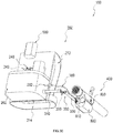
- System 100 optionally includes connecting member 300 (not shown).
- FIG. 37 illustrates a perspective view of another exemplary back-mounted power tool system 100 that is partially disintegrated.
- System 100 backpack apparatus 200, power tool 400, power cord 360, connecting member 300, and an adapter 700.
- first arm 330 of connecting member 300 may be removably or fixedly connected to adaptor 700.
- power cord 360 is placed inside connecting member 300, e.g., by passing through the inside of first arm 330 and second arm 340.
- connector 362 of power cord 360 may be placed inside fitting member 310, and connects to power outlet 282 of backpack apparatus 200 when fitting member 310 is inserted and/or coupled to backpack apparatus 200.
- fitting member 310 may include a connector (not shown) that connects power cord 360 to outlet 282 when fitting member 310 is inserted and/or coupled to backpack apparatus 200.
- Adaptor 700 has the same fitting structures as that of battery package 500 and may couple to any connector 240 of system 100. Thus, adapter 700 may be coupled to connector 240 of battery connector 600 of power tool 400 in the same way as that of battery package 500. Adapter 700 may further include electronic circuits that transfers and/or regulates electrical power, voltage, and/or current. In such instances, electrical connection can be achieved between battery package 500 and power tool 400. For example, adaptor 700 may be coupled to battery connector 600 of power tool 400. Power cord 360 may connect to power outlet 282 of backpack apparatus 200 or connect to power outlet 520 of battery package 500 via connector 362 on one end, and connect to adaptor 700, e.g., the electronic circuits inside adaptor 700, on the other end.
- battery package 500 provides electrical power and/or current to power tool 400 while adaptor 700 serves to transfer and/or regulate power and/or current to power tool 400.
- any power tool 400 that has battery connector 600 installed may be used interchangeably in system 100, which increases the versatility and compatibility of system 100.
- this configuration of battery connector 600 shown in FIGS. 36 and 37 allows the user to couple adaptor 700 to power tool 400 by pushing adaptor 700 along with the movement of the user's arm until adaptor 700 is stopped by stopping wall 620 (shown in FIG. 26 ) of battery connector 600.
- this configuration of battery connector 600 allows the user to decouple adaptor 700 from power tool 400 by pulling adaptor 700 along with the movement of the user's arm.
- this configuration of battery connector 600 shown in FIGS. 36 and 37 may increase the convenience and/or ease for the user to couple or remove adaptor 700 when installing or changing power tool 400.
- FIG. 38 illustrates a perspective view of an exemplary system 100.
- System 100 includes may include more than one power tools 400, for example, power tools 400a and 400b.
- each of the power tools 400a and 400b may be any type of power tools selected by the user.
- power tool 400a may be a trimmer and power tool 400b may be a blower.
- power tool 400a may be connected to backpack apparatus 200 via adaptor 700 and connecting member 300.
- the weight of power tool 400a and/or the reaction force generated from the operation of power tool 400a may be transferred to connecting member 300 and then to backpack apparatus 200.
- Power tool 400b may be coupled to battery package 500b and thus may be operated separately from backpack apparatus 200. In such instances, both power tools 400a and 400b may be operated at the same time. For example, one may use one hand operating power tool 400a and the other hand operating power tool 400b.
- FIG. 39 illustrates a perspective view of an exemplary back-mounted power tool system 100.
- FIG. 40 illustrates a back view of system 100 of FIG. 39 .
- FIG. 41 illustrates a side view of system 100 of FIG. 39 .
- FIG. 42 illustrates another back view of system 100 of FIG. 39 .
- FIG. 43 illustrates another side view of system 100 of FIG. 39 .
- power tool 400 of system 100 is a grass cutter.
- reference below to power tool 400 may refer to a grass cutter for illustrating exemplary embodiments of system 100 shown in FIGS. 39-43 .
- connecting member 300 of system 100 includes first arm 330, second arm 340, and a cable 366.
- Backpack apparatus 200 includes a connector 390 that is rotatably coupled to second arm 340. The lengths of first arm 330 and second arm 340 may be adjustable, and may be locked to fixed lengths by the user. Cable 366 is attached to connector 390 at one end, passes through the inside of second arm 340 and first arm 330, and is attached to power tool 400 at the other end. Cable 366 thus may transfer at least a part of the weight of power tool 400 to connector 390, which then transfers the weight to backpack harness 210 to be carried by the shoulders, back, and/or waist of the user.
- first arm 330 and second arm 340 are illustrated in FIG. 39 .
- Axis S2 indicates a vertical direction and axis S1 indicates a horizontal direction.
- axis S2 is substantially parallel to the direction of the gravitational force.
- Second arm 340 may rotate around or about axis S1 to allow connecting member 300 to be moved to a position desired by the user. For example, as shown in FIGS. 42 and 43 , connecting member 300 is moved to the right of the user. In other instances, connecting member 300 may be moved to any suitable position around the user for operating power tool 400.
- First arm 330 rotatably connects to second arm 340, e.g., via hinge 380, as shown in FIG. 39 .
- the rotational angle between first arm 330 and second arm 340 may be adjustable. As shown in FIG. 39 , the rotational axis of first arm 330 relative to second arm 340 is perpendicular to both axes S1 and S2. Thus, power tool 400 may be poisoned to be at a suitable height and/or angle by adjusting the rotational angle of first arm 330 relative to second arm 340. Similarly, the rotational angle between first arm 330 and second arm 340 may be adjusted such that any particular type of power tool 400 can be at a position with a suitable height and/or angle for the user to operate.
- connector 390 further includes a winding device, such as a reel that cable 366 may be wound.
- a winding device such as a reel that cable 366 may be wound.
- the reel of the winding device may be turned manually or automatically to adjust the length of cable 366 such that power tool 400 is at a suitable height and/or angle.
- power tool 400 may include a user control, such as a button or a nob, which is connected to electronic control circuits of backpack apparatus 200. The button or nob may allow the user to adjust the length of cable 366 as needed.
- FIG. 44 illustrates a perspective view of an exemplary back-mounted power tool system 100.
- FIG. 45 illustrates a perspective view of system 100 of FIG. 44 with some parts illustrated in a partially exploded view.
- FIG. 46 illustrates a perspective view of system 100 of FIG. 44 .
- FIG. 47 illustrates a perspective view of power tool 400 and connecting member 300 of system 100 of FIG. 44 .
- system 100 includes backpack apparatus 200, power tool 400, e.g., a blower, and connecting member 300.
- a motor (not shown) and an air-generating device (not shown) of power tool 400 are installed in chamber 280 of backpack apparatus 200.
- the air-generating device may be a centrifugal fan or a centrifugal propeller.
- the air-generating device may be similar to air-generating device 470 shown in FIGS. 11 and 12 .
- the motor may drive the air-generating device via e.g., a rotational shaft.
- the motor may be similar to motor 460 shown in FIGS. 11 and 12 .
- Backpack apparatus 200 further includes a circuit board (not shown), which is electrically connected to the motor and/or user controls in handle 430.
- the circuit board (similar to circuit board 480 shown in FIGS. 11 and 12 ) may be installed in a chamber of backpack apparatus 200, e.g., chamber 280.
- electrical energy or power is transferred from battery package 500 coupled to connector 240 to the circuit board, from which is transferred to the motor and/or user controls in handle 430.
- chamber 280 of backpack apparatus 200 includes an airflow passage (not shown).
- the air flow passage may be an integral part of backpack apparatus 200 or may be assembled by a plurality of parts.
- the air flow generated by the motor and the air-generating device passes through the air flow passage and enter power tool 400.
- power tool 400 includes pipe 410, a compliant tube 422, and a connecting tube 424.
- the air flow generated by the motor and the air-generating device may pass through a passage formed by the air flow passage in chamber 280, connecting tube 424 and compliant tube 422, and pipe 410.
- connecting tube 424 may have an arc shape suitable for directing the air flow to compliant tube 422 and pipe 410.
- connecting tube 424 may have an arc shape similar to an elbow.
- Compliant tube 422 is flexible and/or extendable. Compliant tube 422 may be moved around, e.g., from side to side in any direction, or upward or downward to allow the user to position power tool 400 at a suitable operational angle.
- Connecting tube 424 may be rotatably connected to backpack apparatus 200.
- FIG. 45 illustrate two axes S3 and S4. Axis S4 is substantially parallel to axis S3. As shown in FIG. 45 , connecting tube 424 may rotate around or about axis S3. The rotation of connecting tube 424 around or about axis S3 may adjust the angle of pipe 410, and thus the direction of the air flow ejected from power tool 400.
- connecting member 300 includes fitting member 310, power tool connector 320, first arm 330, and second arm 340.
- First arm 330 is perpendicular to second arm 340, and may rotate relative to second arm 340 around or about axis S4.
- Connecting member 300 removably connects to backpack apparatus 200 via coupling fitting member 310, and removably connects to power tool 400 via power tool connector 320.
- fitting member 310 may be inserted along axis S3 or an axis perpendicular to axis S3 to a recess of backpack apparatus 200, such as a slot in chamber 280.
- Power tool connector 320 may connect to power tool 400 via a sliding mechanism.
- power tool connector 320 includes a hinge and a protrusion 328.
- the hinge allows power tool connector 320 to rotatably connect to first arm 330.
- Protrusion 328 may be slid into a slot 326 of a clamp on power tool 400.
- the clamp may be a part of power tool 400 or may be installed on power tool 400.
- the clamp may include half members 322 and 324 that may be assembled via any suitable mechanical structure that allows for quick assembly and release, e.g., structures that use friction fit, press fit, twist fit, snap fit, etc. Such sliding connection between power tool connector 320 and power tool 400 may allow connecting member 300 to be easily separated or connected to power tool 400.
- FIG. 48 illustrates a perspective view of an exemplary back-mounted system 100.
- System 100 may include more than one power tools 400, for example, power tools 400a and 400b.
- Battery package 500b is decoupled from connector 240 of backpack apparatus 200 and coupled to power tool 400b.
- Power tool 400b may thus be operated separately from backpack apparatus 200.
- Power tool 400a is coupled to backpack apparatus 200 to obtain power supply from battery package 500a and obtain support from backpack apparatus 200.
- Power tools 400a and 400b may be used at the same time.
- One or more features of this system may be substantially similar to the embodiments described above.
- FIG. 49 illustrates a perspective view of an exemplary back-mounted power tool system 100.
- a motor and an air-generating device may make up a substantial portion of the weight of power tool 400.
- the weight of these two components is transferred to the shoulders, back, and/or waist of the user by backpack apparatus 200.
- system 100 may be simplified by not including connecting member 300.
- System 100 may still allow the user to operate power tool 400 for long periods of time at least because the reduced work and fatigue of the user's arm during the operation of power tool 400, and/or the power supply from battery package 500 or built-in battery cells of backpack apparatus 200.
- FIG. 50 illustrates a perspective view of an exemplary back-mounted system 100.
- FIG. 51 illustrates a partial exploded perspective view of back-mounted power tool system 100 of FIG. 50 .
- system 100 may include backpack apparatus 200, connecting member 300, and power tool 400.
- Body 220 of backpack apparatus 200 includes frame 230, connector 240 to couple battery package 500 to backpack apparatus 200, and/or base member 250.
- frame 230 of backpack apparatus 200 includes one or more handles for the user to grab, hold, and/or carry backpack apparatus 200.
- frame 230 may include a top handle 232 and/or a side handle 234 on the left and/or right side of backpack apparatus 200.
- One or more features of this system may be substantially similar to the embodiments described above.
- connecting member 300 may include power tool connector 320 and one arm 340.
- Power tool connector 320 may rotatably and/or removably connect to power tool 400.
- Arm 340 may rotatably connect power tool connector 320 on one end, and may rotatably and/or removably connect to fitting member 310 that may form a complimentary fit with base member 250 of backpack apparatus 200 or with base member 250 on the other end.
- arm 340 may have a hollow structure that may provide a passage for electrical connections to motor 460 that is located inside pipe 410 (not shown), e.g., electrical wires connecting motor 460 to battery package 500 or backpack apparatus 200.
- FIGS. 52A and 52B illustrate that the orientation of the longitudinal axis of power tool 400 may be adjusted by rotating power tool 400 around or about axis X or Y.
- FIG. 52A illustrates a side view of system 100. As shown in FIG. 52A , power tool 400 may be directed downward or upward to allow the user to position power tool 400 at a suitable operational angle relative to a horizontal plane, e.g., the ground.
- FIG. 52B illustrates a top view of system 100.
- power tool 400 may be directed rightward or leftward to allow the user to position power tool 400 at a suitable operational angle relative to the body of the user, for example.
- These rotational connections may allow power tool 400 to be oriented over a spherical space.
- these rotational connections may be designed to rotate power tool 400 within predetermined ranges to improve the safety of the user during operation and/or flexibility for controlling power tool 400.
- FIG. 53 illustrates an exemplary embodiment of power tool 400.
- FIG. 54 illustrates an exploded perspective view of power tool 400 of FIG. 53 .
- FIG. 55 illustrates a cross-section of the power tool of FIG. 53 .
- pipe 410 of power tool 400 may include a plurality of parts.
- Pipe 410 may include an inlet pipe 411, an outlet pipe 413, and a compliant pipe 422 connecting inlet pipe 411 and outlet pipe 413.
- Airway 412 inside inlet pipe 411 may become narrower from inlet 414 along the length of inlet pipe 411.
- Pipe 410 may further include a protective housing 491 that may removably cover the external surface of inlet pipe 411.
- protective housing 491 may include two half members 491 a and 491b that may be clamped together via any suitable mechanical means, such as friction fit, press fit, twist fit, snap fit, etc.
- Protective housing 491 may create ventilated chamber 490 that is formed between the external surface of inlet pipe 411 and interior surface of protective housing 491.
- circuit board 480 may be installed in chamber 490 which may allow cooling of circuit board 480 when power tool 400 operates.
- Compliant tube 422 may be removably or fixedly connected to inlet pipe 411.
- at least a part of inlet pipe 411 may frictionally fit into compliant tube 422 via a suitable mechanical means, e.g., friction fit, press fit, twist fit, snap fit, overmolding or molding, thermal bonding, adhesive bonding, and/or welding.
- Protective housing 491 and/or two half members 491a and 491b may then clamp, tighten, and/or lock compliant pipe 422 onto inlet pipe 411.
- compliant pipe 422 may at least partially overlap with inlet pipe 411 and outlet pipe 413.
- one end of compliant tube 422 may be at least partially concentrically enclosing inlet pipe 411, and the other end of compliant tube 422 may be at least partially concentrically enclosing outlet pipe 413.
- Compliant pipe 422 is flexible, bendable, and/or extendable. Compliant pipe 422 may be moved around, e.g., from side to side in any direction, or upward or downward to allow the user to position power tool 400 at a suitable operational angle or toward a suitable direction.
- FIG. 56 illustrates a side view of system 100 including power tool 400 of FIG. 53 . As shown in FIG. 56 , power tool 400 may be oriented upward by rotating power tool 400 around or about power tool connector 320 and/or by extending and bending compliant pipe 422. Compliant pipe 422 may be bent and/or extended in any suitable direction as needed to facilitate and/or increase the convenience for the user's operation of power tool 400.
- power tool 400 includes motor housing 450 having motor 460 installed therein.
- Motor 460 is connected to air-generating device 470 via a motor shaft.
- Motor housing 450 and air-generating device 470 may be located at any suitable position in airway 412 inside pipe 410, such as an suitable position in inlet pipe 411, compliant pipe 422, and/or outlet pipe 413.
- air-generating device 470 is located in inlet pipe 411 and motor housing 450 is at least partially located in inlet pipe 411 and partially extended into compliant pipe 422.
- the extension of motor housing 450 into compliant pipe 422 is determined such that the portion of motor housing 450 inside compliant pipe 422 may not substantially affect the bendability and/or flexibility of compliant pipe 422.
- length B the natural length of compliant tube 422 (without any force applied) is referred to as length B.
- the amount of overlap between compliant tube 422 and inlet pipe 411 is referred to as length A.
- the length of motor housing 450 extended into compliant tube 422 is referred to as length C.
- the length of the part of compliant tube 422 that remain substantially flexible, i.e., not overlapping with inlet pipe 411, motor housing 450, and outlet pipe 413, is referred to as length D.
- length A may range from about 20% to about 50% of length B.
- length C may range from about 10% to 30% of length D.
- outlet pipe 413 may be extendible by including one or more extension pipes.
- the extension pipes may themselves be extendible or have extendible connections between them.
- outlet pipe 413 includes three extension pipes 413a, 413b, and 413c.
- Outlet pipe 413 may be extended by adjusting extendible connections 415 between extension pipes 413a and 413b and between extension pipes 413b and 413c.
- Each extendible connection 415 may include a first fitting part 415a and a second fitting part 415b that are installed on or part of an extension pipe. The relative movement between fitting parts 415a and 415b may allow adjustment of the length of outlet pipe 413 by adjusting the amount of overlap between the extension pipes.
- fitting part 415a may be at one end of extension pipe 413a and fitting part 415b may be at one end of extension pipe 413b.
- Extension pipe 413a may partially and rotatably fit into extension pipe 413b by fitting part 415a into part 415b via a suitable mechanical means, e.g., friction fit, press fit, twist fit, snap fit, etc.
- Fitting part 415a may include a protrusion that may extend beyond the external surface of extension pipe 413a and that may fit into a channel spiraled around fitting part 415b.
- Rotating extension pipe 413b around extension pipe 413a or vice versa may allow the protrusion of fitting part 415a to move along the channel of fitting part 415b such that the overlap between fitting part 415a and 415b may be increased or decreased, depending on the direction of the rotation, e.g., clockwise or counterclockwise.
- Changing the overlap between fitting parts 415a and 415b and/or between extension pipes 413a and 413b may then change the length of outlet pipe 413.
- extendible connection 415 between extension pipes 413b and 413c may use the same mechanical structure and mechanism as described above for adjusting the length of outlet pipe 413.
- Outlet pipe 413 may rotatably connect to compliant pipe 422.
- a ring structure 426 may rotatably and/or frictionally fit onto one end of extension pipe 413a of outlet pipe 413.
- Extension pipe 413a together with ring structure 426 may then partially fit into compliant pipe 422.
- a tightening ring 428 may then tighten and/or clamp compliant tube 422 around ring structure 426 and thus extension pipe 413a. This allows the compliant tube 422 to rotate with ring structure 426 relative to extension pipe 413a.
- extension pipe 413a may include a strengthening structure 417 inside that at least partially supports the interior surface of extension pipe 413a that is clamped and/or tightened by ring structure 426 and/or tightening ring 428.
- ring structure 426 may include one or more protrusions or recesses on its interior surface that are complimentary to one or more recesses or protrusions on the exterior surface of the end of extension pipe 413a.
- the complimentary protrusions and recesses allow the rotation between ring structure 426 and extension pipe 413a to stop at interval places where the protrusions fit into the recesses and to have certain amount of resistance.
- Such stoppable design of the rotatable connection between ring structure 426 and extension pipe 413a reduces the risk of using power tool 400 that may result from over flexible rotation between outlet pipe 413 and compliant tube 422, such as by losing control of the direction of power tool 400.
- power tool 400 may include handle 430 for carrying, steering, cruising, and/or controlling power tool 400.
- handle 430 may be rotatably installed on pipe 410, e.g., via a clamp structure, for example.
- the rotatability of handle 430 around or about pipe 410 may increase the flexibility for operating power tool 400.
- handle 430 may be rotated clockwise or counterclockwise around or about the longitudinal axis of pipe 410 to allow the user to adjust their postures and/or their arms while operating power tool 400 so as to increase the convenience and flexibility of using power tool 400.
- handle 430 may be movable along the longitudinal axis of pipe 410 such that handle 430 may be moved to a position suitable for the length of the user's arm. Such movable design of handle 430 may increase the ease and convenience for operating power tool 400.
- handle 430 may include an operational switch 436 and a safety switch 437 that may be operated by one hand of the user. Operational switch 436 and safety switch 437 may be located at different sides of handle 430, and may be operated by different fingers of the user's hand. Operational switch 436 may allow the user to switch on and/off of power tool 400. To increase the safety for operating power tool 400, in some situations, when safety switch 437 is switched on, power tool 400 cannot be switched on by operational switch 436. In some embodiments, handle 430 may include a power switch (not shown) that when switched on, allows power tool 400 to operate at maximum power, e.g., driving motor 460 at its maximum power.
Landscapes
- Engineering & Computer Science (AREA)
- Mechanical Engineering (AREA)
- Architecture (AREA)
- Civil Engineering (AREA)
- Structural Engineering (AREA)
- Life Sciences & Earth Sciences (AREA)
- Environmental Sciences (AREA)
- Battery Mounting, Suspending (AREA)
- Secondary Cells (AREA)
Claims (24)
- Auf dem Rücken getragenes Motorwerkzeugsystem, umfassend:ein Batteriepaket (500b, 500c), das auch an anderen Motorwerkzeugsystemen verwendet werden kann;ein Motorwerkzeug (400a), das einen Motor umfasst, der von einer Stromversorgung aus dem Batteriepaket angetrieben wird;eine auf dem Rücken getragene Vorrichtung (200), die einen Rucksackgurt zum Befestigen der Rucksackvorrichtung am Körper des Benutzers umfasst,wobei das System dadurch gekennzeichnet ist, dass die Rucksackvorrichtung (200) einen offenen Schlitz (292) aufweist, der dazu ausgelegt ist,das Batteriepaket abnehmbar aufzunehmen, wobei der offene Schlitz einen ersten Verbinder (600) zum Anschließen des Batteriepakets an die Rucksackvorrichtung enthält;ein Verbindungselement (300) zum Übertragen eines Gewichtes des Motorwerkzeugs und/oder einer Kraft, die vom Motorwerkzeug aufgenommen wird, auf die Rucksackvorrichtung durch drehbares Verbinden des Motorwerkzeugs mit der Rucksackvorrichtung,wobei das Verbindungselement dem Motorwerkzeug ermöglicht, um eine erste Rotationsachse und eine zweite Rotationsachse zu rotieren, wobei die erste Rotationsachse senkrecht zur zweiten Rotationsachse ist.
- Auf dem Rücken getragenes Motorwerkzeugsystem nach Anspruch 1, wobei das Batteriepaket ferner eine oder mehr Batteriezellen, ein Gehäuse, das die Batteriezellen umschließt, und ein elektrisches Anschlusselement umfasst.
- Auf dem Rücken getragenes Motorwerkzeugsystem nach Anspruch 2, wobei das Gehäuse ferner Befestigungsstrukturen zum Verbinden des Batteriepaketes mit dem ersten Verbinder umfasst, wobei die Verbindungsstrukturen ein oder mehr Passschlitze umfassen, die komplementär zu einem oder mehr Passelementen des ersten Verbinders sind.
- Auf dem Rücken getragenes Motorwerkzeugsystem nach Anspruch 1, wobei das Motorwerkzeug ein Gebläse oder eine Blas-/Saugvorrichtung ist, wobei das Motorwerkzeug ferner umfasst:einen Propeller, der vom Motor zum Erzeugen eines Luftstroms angetrieben werden kann;einen Luftweg, der einen Durchgang für den Luftstrom bereitstellt;eine elektronische Platine;einen Stromeingang; undeine Benutzersteuerung.
- Auf dem Rücken getragenes Motorwerkzeugsystem nach Anspruch 4, wobei das Motorwerkzeug ferner eine Platinenkammer umfasst, die einen Lufteinlass und einen Luftauslass aufweist, wobei die Elektronikkarte in der Platinenkammer installiert ist.
- Auf dem Rücken getragenes Motorwerkzeugsystem nach Anspruch 4, wobei das Motorwerkzeug ferner umfasst:eine Motorkammer, die einen Lufteinlass und einen Luftauslass hat; undeinen Lüfter, der mit dem Motor verbunden ist,wobei der Motor und der Lüfter in der Motorkammer installiert sind, unddie Motorkammer ist im Luftweg installiert.
- Auf dem Rücken getragenes Motorwerkzeugsystem nach Anspruch 6, wobei der Propeller und der Lüfter sich auf zwei gegenüberliegenden Seiten des Motors befinden und bei Antrieb durch den Motor Luftströme erzeugen, die zwei entgegengesetzte Richtungen haben.
- Auf dem Rücken getragenes Motorwerkzeugsystem nach Anspruch 4, wobei die Benutzersteuerung ein Handgriff zum Einstellen der Bewegung des Motorwerkzeugs ist und sich in der Nähe eines Schwerpunktes des Motorwerkzeugs befindet.
- Auf dem Rücken getragenes Motorwerkzeugsystem nach Anspruch 8, wobei der Handgriff elektronische Schaltungen und/oder Komponenten enthält, die den Betrieb des Motors steuern.
- Auf dem Rücken getragenes Motorwerkzeugsystem nach Anspruch 8, wobei der Handgriff ein oder mehr Polster an seinem Boden umfasst, um eine Wechselwirkung zwischen dem Motorwerkzeug und dem Handgriff zu dämpfen.
- Auf dem Rücken getragenes Motorwerkzeugsystem nach Anspruch 1, wobei die Rucksackvorrichtung ferner ein Basiselement umfasst, wobei das Basiselement eine Auswurfvorrichtung zum Auswerfen des Batteriepaketes enthält.
- Auf dem Rücken getragenes Motorwerkzeugsystem nach Anspruch 11, wobei:das Basiselement ferner ein zweites Verbindungselement enthält; unddas Verbindungselement umfasst ferner ein Passelement zum Verbinden eines Arms des Verbindungselementes mit der Rücksackvorrichtung, wobei das Passelement ein erstes Passelement hat, das mit dem zweiten Verbinder verzahnt ist, und ein zweites Passelement, das drehbar mit dem Arm des Verbindungselementes verbunden ist.
- Auf dem Rücken getragenes Motorwerkzeugsystem nach Anspruch 1, wobei das Verbindungselement ferner einen Motorwerkzeug-Verbinder und einen ersten Arm umfasst, wobei der Motorwerkzeug-Verbinder den ersten Arm mit dem Motorwerkzeug verbindet, wobei der Motorwerkzeug-Verbinder eine Spannvorrichtung umfasst, die sich am Körper des Motorwerkzeugs festklemmt.
- Auf dem Rücken getragenes Motorwerkzeugsystem nach Anspruch 13, wobei das Verbindungselement ferner eine Feder zwischen dem ersten Arm und dem Motorwerkzeug-Verbinder zum Dämpfen der Kraft zwischen dem Motorwerkzeug und dem Verbindungselement umfasst.
- Auf dem Rücken getragenes Motorwerkzeugsystem nach Anspruch 1, umfasst ferner ein Stromkabel, das das Batteriepaket elektrisch mit dem Motorwerkzeug verbindet, wobei das Stromkabel durch eine Innenseite des Verbindungselementes verläuft.
- Auf dem Rücken getragenes Motorwerkzeugsystem nach Anspruch 1, wobei das Motorwerkzeug ferner einen Batterieverbinder umfasst, und das Batteriepaket kann aus der Rucksackvorrichtung entfernt werden und lösbar an den Batterieverbinder angeschlossen werden.
- Auf dem Rücken getragenes Motorwerkzeugsystem nach Anspruch 1, wobei das Motorwerkzeug ausgewählt wird unter einem Gebläse, einer Saugvorrichtung, einer Blas-/Saugvorrichtung, einer Mulchvorrichtung, einem Trimmer, einer Kettensäge, einer Grasschneidemaschine, einem Freischneidegerät, einer Bindemaschine, einer Bohrmaschine, einem Rasenmäher, einer Kreissäge, einem Winkelschleifer, einer Schleifmaschine oder Stichsägen.
- Auf dem Rücken getragenes Motorwerkzeugsystem nach Anspruch 1, wobei ein Gewicht des Batteriepakets im Bereich von 30 % bis 150 % eines Gewichtes des Motorwerkzeugs liegt oder größer als 1 Kilogramm ist.
- Auf dem Rücken getragenes Motorwerkzeugsystem nach Anspruch 1, das ferner ein zweites Motorwerkzeug umfasst, das elektrisch mit dem Batteriepaket verbunden ist.
- Auf dem Rücken getragenes Motorwerkzeugsystem nach Anspruch 1,
wobei das Verbindungselement einen ersten Arm (330) umfasst, der mit dem Motorwerkzeug verbunden ist, und einen zweiten Arm (340), der mit der Rucksackvorrichtung verbunden ist, wobei der erste Arm drehbar mit dem zweiten Arm verbunden ist, und
wobei der erste Arm so funktioniert, das er um die erste Rotationsachse rotiert, die durch ein Gelenk des ersten Arms und des zweiten Arms verläuft, und der zweite Arm funktioniert so, dass er um die zweite Rotationsachse rotiert, die sich durch den zweiten Arm und senkrecht zur ersten Rotationsachse erstreckt. - Auf dem Rücken getragenes Motorwerkzeugsystem nach Anspruch 20, das ferner ein nachgiebiges Element zwischen dem ersten Arm und dem Motorwerkzeug umfasst, um eine Kraft zu dämpfen, die während des Betriebs des Motorwerkzeuges erzeugt wird.
- Auf dem Rücken getragenes Motorwerkzeugsystem nach Anspruch 20, wobei das Verbindungselement ferner umfasst:ein erstes Passelement, das mit einem zweiten Verbinder verzahnt ist, der sich an einem Boden der Rucksackvorrichtung befindet; undein zweites Passelement, das drehbar mit dem zweiten Arm verbunden ist, wobei der zweite Arm zumindest teilweise in einen Hohlraum des zweiten Passelementes passt.
- Auf dem Rücken getragenes Motorwerkzeugsystem nach Anspruch 22, wobei das Verbindungselement ferner umfasst:einen Verstärkungsarm, der im Hohlraum des zweiten Passelementes installiert ist und zumindest teilweise in den zweiten Arm passt,wobei der zweite Arm durch den Verstärkungsarm von einer Innenseite des zweiten Arms und durch das zweite Passelement von einer Außenseite des zweiten Arms gestützt wird.
- Auf dem Rücken getragenes Motorwerkzeugsystem nach Anspruch 22, wobei:der zweite Verbinder, der sich am Boden der Rucksackvorrichtung befindet, einen oder mehr Aufnahmeschlitze, eine oder mehr Führungsrippen und einen Verriegelungsschlitz umfasst; unddas erste Passelement des Verbindungselementes einen oder mehr längliche Dornen umfasst, die in einen oder mehr Aufnahmeschlitze, einen oder mehr Führungsschlitze passen, um die eine oder mehr Führungsrippen aufzunehmen, und eine Verriegelungsstruktur zum Verriegeln des Verriegelungsschlitzes.
Applications Claiming Priority (7)
| Application Number | Priority Date | Filing Date | Title |
|---|---|---|---|
| CN201510272506 | 2015-05-25 | ||
| CN201510272609 | 2015-05-25 | ||
| CN201510287347 | 2015-05-29 | ||
| CN201510621441.8A CN106181901B (zh) | 2015-05-25 | 2015-09-25 | 背负式工具系统 |
| CN201510623933.0A CN106181902B (zh) | 2015-05-25 | 2015-09-25 | 背负式工具系统 |
| CN201510624884.2A CN106192835B (zh) | 2015-05-25 | 2015-09-25 | 电动工具系统和背负式风机系统 |
| CN201610070425 | 2016-02-01 |
Publications (3)
| Publication Number | Publication Date |
|---|---|
| EP3106565A2 EP3106565A2 (de) | 2016-12-21 |
| EP3106565A3 EP3106565A3 (de) | 2017-07-05 |
| EP3106565B1 true EP3106565B1 (de) | 2019-10-23 |
Family
ID=56404962
Family Applications (1)
| Application Number | Title | Priority Date | Filing Date |
|---|---|---|---|
| EP16169934.3A Active EP3106565B1 (de) | 2015-05-25 | 2016-05-17 | Rückseitig montierte elektrowerkzeugsysteme und verfahren zur verwendung |
Country Status (3)
| Country | Link |
|---|---|
| US (2) | US10039367B2 (de) |
| EP (1) | EP3106565B1 (de) |
| AU (1) | AU2016100638A4 (de) |
Families Citing this family (41)
| Publication number | Priority date | Publication date | Assignee | Title |
|---|---|---|---|---|
| US10039367B2 (en) | 2015-05-25 | 2018-08-07 | Chevron (Hk) Limited | Back-mounted power tool systems and methods of use |
| WO2017143922A1 (zh) * | 2016-02-22 | 2017-08-31 | 常州格力博有限公司 | 背负式工作器具、背负式吹风机以及控制手柄组件 |
| JP2017172198A (ja) * | 2016-03-23 | 2017-09-28 | 株式会社やまびこ | 送風作業装置 |
| DE102017204153A1 (de) | 2017-03-14 | 2018-09-20 | Robert Bosch Gmbh | Mechanische Elektrowerkzeug/Akkupack-Schnittstelle sowie Elektrowerkzeug |
| CN110475469B (zh) | 2017-03-30 | 2022-03-22 | 格力博(江苏)股份有限公司 | 背负式工作器具 |
| US11695312B2 (en) | 2017-09-01 | 2023-07-04 | Milwaukee Electric Tool Corporation | Electrostatic discharge dissipation structure |
| US10892449B2 (en) * | 2017-09-06 | 2021-01-12 | Nanjing Chervon Industry Co., Ltd. | Backpack tool system and backpack power supply apparatus thereof |
| WO2019061094A1 (en) | 2017-09-27 | 2019-04-04 | Changzhou Globe Co., Ltd. | CARRIER ASSEMBLY FOR HARNESS |
| ES2966117T3 (es) * | 2017-09-27 | 2024-04-18 | Globe Jiangsu Co Ltd | Conjunto portador ajustable para un arnés |
| US20200253360A1 (en) * | 2017-10-13 | 2020-08-13 | Briggs & Stratton Corporation | Power tool having a backpack-housed power supply |
| CN108086214B (zh) * | 2018-01-26 | 2023-07-04 | 张伟 | 一种室外清扫机器人 |
| US20190231054A1 (en) * | 2018-01-29 | 2019-08-01 | Clam Corporation | Fishing Gear Harness Assembly |
| DE102018118552A1 (de) | 2018-07-31 | 2020-02-06 | Wacker Neuson Produktion GmbH & Co. KG | Tragvorrichtung mit Energiespeicher und elektrischem Umformer |
| EP3622849B1 (de) | 2018-09-17 | 2022-11-02 | Andreas Stihl AG & Co. KG | Rückentragvorrichtung, insbesondere für einen akkupack |
| FR3092597B1 (fr) | 2019-02-07 | 2021-01-15 | Pellenc Sa | Equipement de souffleur pourvu d'un harnais de portage au dos |
| JP7261664B2 (ja) * | 2019-06-14 | 2023-04-20 | 株式会社マキタ | ブロワ |
| AU2020205211B2 (en) * | 2019-08-02 | 2026-01-15 | Techtronic Cordless Gp | Blowers having noise reduction features |
| US11858106B2 (en) | 2019-08-08 | 2024-01-02 | Black & Decker Inc. | Power tools and power tools platform |
| DE102020005909A1 (de) * | 2019-10-07 | 2021-04-08 | Makita Corporation | Heckenschere |
| EP4074462B1 (de) | 2019-12-13 | 2026-05-06 | Positec Power Tools (Suzhou) Co., Ltd | Steuervorrichtung und elektrisches werkzeugsystem |
| CN113013659B (zh) * | 2019-12-19 | 2023-11-10 | 金风科技股份有限公司 | 防扭连接器、电缆连接装置及风力发电机组 |
| JP7375661B2 (ja) * | 2020-04-08 | 2023-11-08 | 三菱電機株式会社 | 電気掃除機 |
| US11261782B1 (en) | 2020-04-24 | 2022-03-01 | Donald W. Alvis | Portable AC power pack |
| US20230318329A1 (en) | 2020-08-25 | 2023-10-05 | Makita Corporation | Electrical apparatus and apparatus system |
| US12064894B2 (en) | 2020-09-04 | 2024-08-20 | Milwaukee Electric Tool Corporation | Chainsaw |
| CN112343847A (zh) * | 2020-11-17 | 2021-02-09 | 格力博(江苏)股份有限公司 | 背负式吹风机 |
| WO2022105587A1 (en) * | 2020-11-17 | 2022-05-27 | Globe (jiangsu) Co., Ltd. | Backpack blower, backpack assembly and backpack power assembly |
| USD979488S1 (en) * | 2020-12-21 | 2023-02-28 | Zhanyi Liu | Battery |
| JP7519926B2 (ja) * | 2021-01-22 | 2024-07-22 | 株式会社マキタ | 集じん機 |
| WO2022262681A1 (zh) * | 2021-06-15 | 2022-12-22 | 格力博(江苏)股份有限公司 | 一种背负式电源设备和背负式工具系统 |
| US12089540B2 (en) * | 2021-09-17 | 2024-09-17 | Justin Misenheimer | Backpack blower converter attachment |
| WO2023093606A1 (zh) * | 2021-11-24 | 2023-06-01 | 格力博(江苏)股份有限公司 | 一种耦合装置及背负式园林工具系统 |
| JP7768823B2 (ja) * | 2022-04-20 | 2025-11-12 | 株式会社マキタ | ブロワ |
| EP4394158B1 (de) * | 2022-12-28 | 2026-02-18 | Nanjing Chervon Industry Co., Ltd. | Tragbares grabwerkzeug |
| DE102023107131A1 (de) * | 2023-03-21 | 2024-09-26 | Andreas Stihl Ag & Co. Kg | Verbindungsvorrichtung zwischen einem Führungsschaft eines Arbeitsgerätes und einem Exoskelett |
| US12185666B2 (en) * | 2023-04-12 | 2025-01-07 | William Shaw Stewart | Weed trimmer apparatus and system |
| DE102023205363A1 (de) * | 2023-06-09 | 2024-12-12 | Robert Bosch Gesellschaft mit beschränkter Haftung | Handwerkzeugmaschine, insbesondere Schleifmaschine, Handwerkzeugmaschinenvorrichtung, Schutzvorrichtung, Handwerkzeugmaschinensystem und Verfahren zur Herstellung einer Handwerkzeugmaschinenvorrichtung |
| US20250093128A1 (en) * | 2023-09-20 | 2025-03-20 | Bownuts, Llc | Body stabilizer device |
| EP4553229B1 (de) * | 2023-11-07 | 2026-03-04 | Grau Maquinaria i Servei Integral, S.A. | Blaszubehörausrüstung für eine kehrmaschine oder ähnliche strassenreinigungsmaschine |
| SE2450008A1 (en) * | 2024-01-08 | 2025-06-24 | Husqvarna Ab | Tool carrying harness with shoulder strap height adjuster |
| AU2024204274A1 (en) * | 2024-06-21 | 2026-01-15 | SAPP Australia Pty Ltd (trading as SAPP International) | Retail tool holder |
Family Cites Families (38)
| Publication number | Priority date | Publication date | Assignee | Title |
|---|---|---|---|---|
| US4325163A (en) | 1980-04-07 | 1982-04-20 | Allegretti & Company | Portable blower-vacuum unit |
| US4723893A (en) | 1985-07-10 | 1988-02-09 | 501 Komatsu Zenoah Company | Portable blower |
| US5620121A (en) | 1995-05-17 | 1997-04-15 | Watson; Elton G. | Quick releasing support for line trimmers |
| US6105206A (en) | 1999-04-13 | 2000-08-22 | Department Of Water And Power City Of Los Angeles | Portable electrically powered blower apparatus |
| DE20121013U1 (de) | 2001-12-28 | 2002-03-14 | Dolking Ltd., Hong Kong | Elektrowerkzeug mit verbessertem Stromversorgungssystem |
| US6928693B1 (en) * | 2002-10-07 | 2005-08-16 | William A. Ericson | Blower with dual tubes |
| SE0300389D0 (sv) | 2003-02-12 | 2003-02-12 | Electrolux Ab | Handle arrangement for a blower |
| US7600290B1 (en) * | 2003-09-02 | 2009-10-13 | Twindstorm Llc | Multi-blower |
| US7015675B1 (en) | 2004-02-02 | 2006-03-21 | Jorge Andre | Portable power tool and power supply combination |
| US7845048B1 (en) | 2005-06-21 | 2010-12-07 | Gerald Bailey | Portable air-blower for removing debris and the like from a putting green surface |
| DE102005046227B4 (de) | 2005-09-28 | 2009-10-01 | Andreas Stihl Ag & Co. Kg | Arbeitsgerät mit Einhand- und Zeihandbedienung |
| US8032980B2 (en) | 2007-07-10 | 2011-10-11 | Mtd Products Inc | Harness for backpack blower |
| JP4510910B2 (ja) | 2008-07-22 | 2010-07-28 | 株式会社協同 | ブロアー |
| JP5427521B2 (ja) | 2009-09-04 | 2014-02-26 | 株式会社マキタ | 電池パック |
| DE102009040494B4 (de) | 2009-09-08 | 2019-09-05 | Andreas Stihl Ag & Co. Kg | Rückengetragenes Arbeitsgerät |
| DE102009040493A1 (de) | 2009-09-08 | 2011-03-10 | Andreas Stihl Ag & Co. Kg | Rückengetragenes Arbeitsgerät |
| JP2011127541A (ja) | 2009-12-18 | 2011-06-30 | Makita Corp | 背負式作業具 |
| JP5432761B2 (ja) | 2010-02-12 | 2014-03-05 | 株式会社マキタ | 複数のバッテリパックを電源とする電動工具 |
| FR2964987B1 (fr) | 2010-09-20 | 2012-10-05 | Pellenc Sa | Souffleur electroportatif. |
| US9277844B1 (en) * | 2010-10-25 | 2016-03-08 | Luis A. Millan | Apparatus for vacuum and sweeping |
| US9332694B2 (en) * | 2011-03-18 | 2016-05-10 | Andreas Stihl Ag & Co. Kg | Blower apparatus |
| FR2973815B1 (fr) | 2011-04-07 | 2014-08-29 | Pellenc Sa | Souffleur electroportatif autonome a vitesse de sortie d'air modulable |
| US8671516B1 (en) * | 2011-08-09 | 2014-03-18 | Adelmo Mendez | Gas-powered dual-hosed blower |
| CN104303331A (zh) | 2012-03-19 | 2015-01-21 | 胡斯华纳有限公司 | 用于背包能源的载体系统、能源以及背包能源组件 |
| US8549699B1 (en) * | 2012-03-23 | 2013-10-08 | Francisco A. Domingo | Illuminated leaf blower |
| US9167751B2 (en) | 2012-07-09 | 2015-10-27 | Techtronic Outdoor Products Technology Limited | Backpack leaf blower |
| DE102012021000A1 (de) * | 2012-10-26 | 2014-05-15 | Andreas Stihl Ag & Co. Kg | Tragbares Arbeitsgerät mit Gurten |
| AU2013263811B2 (en) | 2012-12-03 | 2018-03-15 | International Mowers Pty Ltd | Motorised Portable Blower Apparatus |
| CA2902577C (en) | 2013-03-14 | 2019-06-11 | Ekso Bionics, Inc. | Non-anthropomorphic hip joint locations for exoskeletons |
| US20140291362A1 (en) | 2013-03-28 | 2014-10-02 | Scala Victor | Tool holster for attachment to leg |
| JP2015082989A (ja) | 2013-10-25 | 2015-04-30 | 株式会社マキタ | 背負式作業機 |
| JP6165588B2 (ja) * | 2013-10-25 | 2017-07-19 | 株式会社マキタ | 作業機 |
| DE202013011447U1 (de) | 2013-12-21 | 2014-02-06 | Calmdura Gmbh | Tragesystem für modulare Batterieeinheit |
| EP3345521B2 (de) * | 2014-04-24 | 2023-05-24 | Husqvarna AB | Laubbläser mit einer öse |
| JP6368616B2 (ja) * | 2014-10-21 | 2018-08-01 | 株式会社マキタ | 動力送風作業機 |
| US9907234B2 (en) * | 2014-11-20 | 2018-03-06 | Black & Decker, Inc. | Battery-powered backpack blower |
| DE102015000731B4 (de) * | 2015-01-21 | 2025-07-24 | Andreas Stihl Ag & Co. Kg | Anordnung mit einem handgeführten Arbeitsgerät und mit einer Abstützvorrichtung und handgeführtes Arbeitsgerät |
| US10039367B2 (en) | 2015-05-25 | 2018-08-07 | Chevron (Hk) Limited | Back-mounted power tool systems and methods of use |
-
2016
- 2016-04-14 US US15/098,898 patent/US10039367B2/en active Active
- 2016-05-17 AU AU2016100638A patent/AU2016100638A4/en not_active Expired
- 2016-05-17 EP EP16169934.3A patent/EP3106565B1/de active Active
-
2018
- 2018-03-26 US US15/935,572 patent/US10736403B2/en active Active
Non-Patent Citations (1)
| Title |
|---|
| None * |
Also Published As
| Publication number | Publication date |
|---|---|
| US10039367B2 (en) | 2018-08-07 |
| US20160345714A1 (en) | 2016-12-01 |
| EP3106565A2 (de) | 2016-12-21 |
| US20180206620A1 (en) | 2018-07-26 |
| EP3106565A3 (de) | 2017-07-05 |
| US10736403B2 (en) | 2020-08-11 |
| AU2016100638A4 (en) | 2016-07-07 |
Similar Documents
| Publication | Publication Date | Title |
|---|---|---|
| US10736403B2 (en) | Back-mounted power tool systems and methods of use | |
| CN106194789B (zh) | 背负式风机系统 | |
| US12082535B2 (en) | Axial-fan blower | |
| US20200253360A1 (en) | Power tool having a backpack-housed power supply | |
| EP3420807B1 (de) | Rucksacksgebläse und betätigungsgriffanordnung | |
| US12330284B2 (en) | Hand-held electrically powered device | |
| JP2013521136A (ja) | バッテリー駆動電動工具 | |
| US20160270458A1 (en) | Cooling backpack apparatus | |
| WO2018007111A1 (en) | Portable electric tool system | |
| CN207269427U (zh) | 修枝机 | |
| CN107022968B (zh) | 背负式风机系统 | |
| CA2929011C (en) | Back-mounted power tool systems and methods of use | |
| CN106192836B (zh) | 背负式风机系统 | |
| CN112900334A (zh) | 一种背负式吹风机 | |
| CN207505510U (zh) | 修枝机 | |
| WO2020264290A1 (en) | Corrugated tube for blower and blower | |
| CN222749621U (zh) | 电池包 | |
| CN222620005U (zh) | 电池包 | |
| US20260014596A1 (en) | Brush pole assembly with integrated air system |
Legal Events
| Date | Code | Title | Description |
|---|---|---|---|
| PUAI | Public reference made under article 153(3) epc to a published international application that has entered the european phase |
Free format text: ORIGINAL CODE: 0009012 |
|
| STAA | Information on the status of an ep patent application or granted ep patent |
Free format text: STATUS: THE APPLICATION HAS BEEN PUBLISHED |
|
| AK | Designated contracting states |
Kind code of ref document: A2 Designated state(s): AL AT BE BG CH CY CZ DE DK EE ES FI FR GB GR HR HU IE IS IT LI LT LU LV MC MK MT NL NO PL PT RO RS SE SI SK SM TR |
|
| AX | Request for extension of the european patent |
Extension state: BA ME |
|
| PUAL | Search report despatched |
Free format text: ORIGINAL CODE: 0009013 |
|
| AK | Designated contracting states |
Kind code of ref document: A3 Designated state(s): AL AT BE BG CH CY CZ DE DK EE ES FI FR GB GR HR HU IE IS IT LI LT LU LV MC MK MT NL NO PL PT RO RS SE SI SK SM TR |
|
| AX | Request for extension of the european patent |
Extension state: BA ME |
|
| RIC1 | Information provided on ipc code assigned before grant |
Ipc: B25F 5/02 20060101ALI20170601BHEP Ipc: E01H 1/08 20060101AFI20170601BHEP |
|
| STAA | Information on the status of an ep patent application or granted ep patent |
Free format text: STATUS: REQUEST FOR EXAMINATION WAS MADE |
|
| 17P | Request for examination filed |
Effective date: 20180104 |
|
| RBV | Designated contracting states (corrected) |
Designated state(s): AL AT BE BG CH CY CZ DE DK EE ES FI FR GB GR HR HU IE IS IT LI LT LU LV MC MK MT NL NO PL PT RO RS SE SI SK SM TR |
|
| STAA | Information on the status of an ep patent application or granted ep patent |
Free format text: STATUS: EXAMINATION IS IN PROGRESS |
|
| 17Q | First examination report despatched |
Effective date: 20180522 |
|
| GRAP | Despatch of communication of intention to grant a patent |
Free format text: ORIGINAL CODE: EPIDOSNIGR1 |
|
| STAA | Information on the status of an ep patent application or granted ep patent |
Free format text: STATUS: GRANT OF PATENT IS INTENDED |
|
| INTG | Intention to grant announced |
Effective date: 20190731 |
|
| GRAS | Grant fee paid |
Free format text: ORIGINAL CODE: EPIDOSNIGR3 |
|
| GRAA | (expected) grant |
Free format text: ORIGINAL CODE: 0009210 |
|
| STAA | Information on the status of an ep patent application or granted ep patent |
Free format text: STATUS: THE PATENT HAS BEEN GRANTED |
|
| AK | Designated contracting states |
Kind code of ref document: B1 Designated state(s): AL AT BE BG CH CY CZ DE DK EE ES FI FR GB GR HR HU IE IS IT LI LT LU LV MC MK MT NL NO PL PT RO RS SE SI SK SM TR |
|
| REG | Reference to a national code |
Ref country code: GB Ref legal event code: FG4D |
|
| REG | Reference to a national code |
Ref country code: CH Ref legal event code: EP |
|
| REG | Reference to a national code |
Ref country code: IE Ref legal event code: FG4D |
|
| REG | Reference to a national code |
Ref country code: DE Ref legal event code: R096 Ref document number: 602016022780 Country of ref document: DE |
|
| REG | Reference to a national code |
Ref country code: AT Ref legal event code: REF Ref document number: 1193745 Country of ref document: AT Kind code of ref document: T Effective date: 20191115 |
|
| REG | Reference to a national code |
Ref country code: NL Ref legal event code: MP Effective date: 20191023 |
|
| REG | Reference to a national code |
Ref country code: LT Ref legal event code: MG4D |
|
| PG25 | Lapsed in a contracting state [announced via postgrant information from national office to epo] |
Ref country code: PL Free format text: LAPSE BECAUSE OF FAILURE TO SUBMIT A TRANSLATION OF THE DESCRIPTION OR TO PAY THE FEE WITHIN THE PRESCRIBED TIME-LIMIT Effective date: 20191023 Ref country code: LT Free format text: LAPSE BECAUSE OF FAILURE TO SUBMIT A TRANSLATION OF THE DESCRIPTION OR TO PAY THE FEE WITHIN THE PRESCRIBED TIME-LIMIT Effective date: 20191023 Ref country code: NL Free format text: LAPSE BECAUSE OF FAILURE TO SUBMIT A TRANSLATION OF THE DESCRIPTION OR TO PAY THE FEE WITHIN THE PRESCRIBED TIME-LIMIT Effective date: 20191023 Ref country code: NO Free format text: LAPSE BECAUSE OF FAILURE TO SUBMIT A TRANSLATION OF THE DESCRIPTION OR TO PAY THE FEE WITHIN THE PRESCRIBED TIME-LIMIT Effective date: 20200123 Ref country code: SE Free format text: LAPSE BECAUSE OF FAILURE TO SUBMIT A TRANSLATION OF THE DESCRIPTION OR TO PAY THE FEE WITHIN THE PRESCRIBED TIME-LIMIT Effective date: 20191023 Ref country code: LV Free format text: LAPSE BECAUSE OF FAILURE TO SUBMIT A TRANSLATION OF THE DESCRIPTION OR TO PAY THE FEE WITHIN THE PRESCRIBED TIME-LIMIT Effective date: 20191023 Ref country code: GR Free format text: LAPSE BECAUSE OF FAILURE TO SUBMIT A TRANSLATION OF THE DESCRIPTION OR TO PAY THE FEE WITHIN THE PRESCRIBED TIME-LIMIT Effective date: 20200124 Ref country code: PT Free format text: LAPSE BECAUSE OF FAILURE TO SUBMIT A TRANSLATION OF THE DESCRIPTION OR TO PAY THE FEE WITHIN THE PRESCRIBED TIME-LIMIT Effective date: 20200224 Ref country code: FI Free format text: LAPSE BECAUSE OF FAILURE TO SUBMIT A TRANSLATION OF THE DESCRIPTION OR TO PAY THE FEE WITHIN THE PRESCRIBED TIME-LIMIT Effective date: 20191023 Ref country code: BG Free format text: LAPSE BECAUSE OF FAILURE TO SUBMIT A TRANSLATION OF THE DESCRIPTION OR TO PAY THE FEE WITHIN THE PRESCRIBED TIME-LIMIT Effective date: 20200123 |
|
| PG25 | Lapsed in a contracting state [announced via postgrant information from national office to epo] |
Ref country code: IS Free format text: LAPSE BECAUSE OF FAILURE TO SUBMIT A TRANSLATION OF THE DESCRIPTION OR TO PAY THE FEE WITHIN THE PRESCRIBED TIME-LIMIT Effective date: 20200224 Ref country code: RS Free format text: LAPSE BECAUSE OF FAILURE TO SUBMIT A TRANSLATION OF THE DESCRIPTION OR TO PAY THE FEE WITHIN THE PRESCRIBED TIME-LIMIT Effective date: 20191023 Ref country code: HR Free format text: LAPSE BECAUSE OF FAILURE TO SUBMIT A TRANSLATION OF THE DESCRIPTION OR TO PAY THE FEE WITHIN THE PRESCRIBED TIME-LIMIT Effective date: 20191023 |
|
| PG25 | Lapsed in a contracting state [announced via postgrant information from national office to epo] |
Ref country code: AL Free format text: LAPSE BECAUSE OF FAILURE TO SUBMIT A TRANSLATION OF THE DESCRIPTION OR TO PAY THE FEE WITHIN THE PRESCRIBED TIME-LIMIT Effective date: 20191023 |
|
| REG | Reference to a national code |
Ref country code: DE Ref legal event code: R097 Ref document number: 602016022780 Country of ref document: DE |
|
| PG2D | Information on lapse in contracting state deleted |
Ref country code: IS |
|
| PG25 | Lapsed in a contracting state [announced via postgrant information from national office to epo] |
Ref country code: DK Free format text: LAPSE BECAUSE OF FAILURE TO SUBMIT A TRANSLATION OF THE DESCRIPTION OR TO PAY THE FEE WITHIN THE PRESCRIBED TIME-LIMIT Effective date: 20191023 Ref country code: EE Free format text: LAPSE BECAUSE OF FAILURE TO SUBMIT A TRANSLATION OF THE DESCRIPTION OR TO PAY THE FEE WITHIN THE PRESCRIBED TIME-LIMIT Effective date: 20191023 Ref country code: RO Free format text: LAPSE BECAUSE OF FAILURE TO SUBMIT A TRANSLATION OF THE DESCRIPTION OR TO PAY THE FEE WITHIN THE PRESCRIBED TIME-LIMIT Effective date: 20191023 Ref country code: ES Free format text: LAPSE BECAUSE OF FAILURE TO SUBMIT A TRANSLATION OF THE DESCRIPTION OR TO PAY THE FEE WITHIN THE PRESCRIBED TIME-LIMIT Effective date: 20191023 Ref country code: CZ Free format text: LAPSE BECAUSE OF FAILURE TO SUBMIT A TRANSLATION OF THE DESCRIPTION OR TO PAY THE FEE WITHIN THE PRESCRIBED TIME-LIMIT Effective date: 20191023 Ref country code: IS Free format text: LAPSE BECAUSE OF FAILURE TO SUBMIT A TRANSLATION OF THE DESCRIPTION OR TO PAY THE FEE WITHIN THE PRESCRIBED TIME-LIMIT Effective date: 20200223 |
|
| REG | Reference to a national code |
Ref country code: AT Ref legal event code: MK05 Ref document number: 1193745 Country of ref document: AT Kind code of ref document: T Effective date: 20191023 |
|
| PLBE | No opposition filed within time limit |
Free format text: ORIGINAL CODE: 0009261 |
|
| STAA | Information on the status of an ep patent application or granted ep patent |
Free format text: STATUS: NO OPPOSITION FILED WITHIN TIME LIMIT |
|
| PG25 | Lapsed in a contracting state [announced via postgrant information from national office to epo] |
Ref country code: IT Free format text: LAPSE BECAUSE OF FAILURE TO SUBMIT A TRANSLATION OF THE DESCRIPTION OR TO PAY THE FEE WITHIN THE PRESCRIBED TIME-LIMIT Effective date: 20191023 Ref country code: SK Free format text: LAPSE BECAUSE OF FAILURE TO SUBMIT A TRANSLATION OF THE DESCRIPTION OR TO PAY THE FEE WITHIN THE PRESCRIBED TIME-LIMIT Effective date: 20191023 Ref country code: SM Free format text: LAPSE BECAUSE OF FAILURE TO SUBMIT A TRANSLATION OF THE DESCRIPTION OR TO PAY THE FEE WITHIN THE PRESCRIBED TIME-LIMIT Effective date: 20191023 |
|
| 26N | No opposition filed |
Effective date: 20200724 |
|
| PG25 | Lapsed in a contracting state [announced via postgrant information from national office to epo] |
Ref country code: SI Free format text: LAPSE BECAUSE OF FAILURE TO SUBMIT A TRANSLATION OF THE DESCRIPTION OR TO PAY THE FEE WITHIN THE PRESCRIBED TIME-LIMIT Effective date: 20191023 Ref country code: AT Free format text: LAPSE BECAUSE OF FAILURE TO SUBMIT A TRANSLATION OF THE DESCRIPTION OR TO PAY THE FEE WITHIN THE PRESCRIBED TIME-LIMIT Effective date: 20191023 |
|
| PG25 | Lapsed in a contracting state [announced via postgrant information from national office to epo] |
Ref country code: CH Free format text: LAPSE BECAUSE OF NON-PAYMENT OF DUE FEES Effective date: 20200531 Ref country code: MC Free format text: LAPSE BECAUSE OF FAILURE TO SUBMIT A TRANSLATION OF THE DESCRIPTION OR TO PAY THE FEE WITHIN THE PRESCRIBED TIME-LIMIT Effective date: 20191023 Ref country code: LI Free format text: LAPSE BECAUSE OF NON-PAYMENT OF DUE FEES Effective date: 20200531 |
|
| REG | Reference to a national code |
Ref country code: BE Ref legal event code: MM Effective date: 20200531 |
|
| PG25 | Lapsed in a contracting state [announced via postgrant information from national office to epo] |
Ref country code: LU Free format text: LAPSE BECAUSE OF NON-PAYMENT OF DUE FEES Effective date: 20200517 |
|
| PG25 | Lapsed in a contracting state [announced via postgrant information from national office to epo] |
Ref country code: IE Free format text: LAPSE BECAUSE OF NON-PAYMENT OF DUE FEES Effective date: 20200517 |
|
| PG25 | Lapsed in a contracting state [announced via postgrant information from national office to epo] |
Ref country code: BE Free format text: LAPSE BECAUSE OF NON-PAYMENT OF DUE FEES Effective date: 20200531 |
|
| PG25 | Lapsed in a contracting state [announced via postgrant information from national office to epo] |
Ref country code: TR Free format text: LAPSE BECAUSE OF FAILURE TO SUBMIT A TRANSLATION OF THE DESCRIPTION OR TO PAY THE FEE WITHIN THE PRESCRIBED TIME-LIMIT Effective date: 20191023 Ref country code: MT Free format text: LAPSE BECAUSE OF FAILURE TO SUBMIT A TRANSLATION OF THE DESCRIPTION OR TO PAY THE FEE WITHIN THE PRESCRIBED TIME-LIMIT Effective date: 20191023 Ref country code: CY Free format text: LAPSE BECAUSE OF FAILURE TO SUBMIT A TRANSLATION OF THE DESCRIPTION OR TO PAY THE FEE WITHIN THE PRESCRIBED TIME-LIMIT Effective date: 20191023 |
|
| PG25 | Lapsed in a contracting state [announced via postgrant information from national office to epo] |
Ref country code: MK Free format text: LAPSE BECAUSE OF FAILURE TO SUBMIT A TRANSLATION OF THE DESCRIPTION OR TO PAY THE FEE WITHIN THE PRESCRIBED TIME-LIMIT Effective date: 20191023 |
|
| PGFP | Annual fee paid to national office [announced via postgrant information from national office to epo] |
Ref country code: DE Payment date: 20250429 Year of fee payment: 10 |
|
| PGFP | Annual fee paid to national office [announced via postgrant information from national office to epo] |
Ref country code: FR Payment date: 20250508 Year of fee payment: 10 |
|
| PGFP | Annual fee paid to national office [announced via postgrant information from national office to epo] |
Ref country code: GB Payment date: 20260323 Year of fee payment: 11 |