EP3106765B1 - Module de chauffage d'eau - Google Patents
Module de chauffage d'eau Download PDFInfo
- Publication number
- EP3106765B1 EP3106765B1 EP16174629.2A EP16174629A EP3106765B1 EP 3106765 B1 EP3106765 B1 EP 3106765B1 EP 16174629 A EP16174629 A EP 16174629A EP 3106765 B1 EP3106765 B1 EP 3106765B1
- Authority
- EP
- European Patent Office
- Prior art keywords
- pump
- housing
- module according
- base plate
- module
- Prior art date
- Legal status (The legal status is an assumption and is not a legal conclusion. Google has not performed a legal analysis and makes no representation as to the accuracy of the status listed.)
- Active
Links
Images


Classifications
-
- F—MECHANICAL ENGINEERING; LIGHTING; HEATING; WEAPONS; BLASTING
- F24—HEATING; RANGES; VENTILATING
- F24D—DOMESTIC- OR SPACE-HEATING SYSTEMS, e.g. CENTRAL HEATING SYSTEMS; DOMESTIC HOT-WATER SUPPLY SYSTEMS; ELEMENTS OR COMPONENTS THEREFOR
- F24D19/00—Details
- F24D19/0097—Casings or frame structures for hydraulic components
-
- F—MECHANICAL ENGINEERING; LIGHTING; HEATING; WEAPONS; BLASTING
- F24—HEATING; RANGES; VENTILATING
- F24D—DOMESTIC- OR SPACE-HEATING SYSTEMS, e.g. CENTRAL HEATING SYSTEMS; DOMESTIC HOT-WATER SUPPLY SYSTEMS; ELEMENTS OR COMPONENTS THEREFOR
- F24D19/00—Details
- F24D19/10—Arrangement or mounting of control or safety devices
- F24D19/1006—Arrangement or mounting of control or safety devices for water heating systems
- F24D19/1051—Arrangement or mounting of control or safety devices for water heating systems for domestic hot water
Definitions
- the present invention relates to a module for heating water with a heat exchanger having a primary portion and a secondary portion, and a pump, which are covered by a thermally insulated cover of a housing.
- the EP0507104A1 discloses a module according to the preamble of the independent claim.
- the EP 2 498 007 A1 and the EP 0 693 657 A1 disclose a thermal insulation device for a hydraulic control group, wherein the thermal insulation encloses the entire hydraulic control group.
- the DE 10 2008 033 773 A1 discloses a housing for a heater and a heater. According to the disclosure of DE 20 2011 104 841 U1 a hydraulic control group is covered by a heat-insulating housing.
- the DE 199 12 284 A1 and the EP 2 093 517 B1 each reveal modules for heating water with a burner and other installations, through which the module becomes a compact heating system, which is suitable to heat a residential unit.
- the module is usually part of an installation in a building for the use of primary energy (for example, heating water, glycol mixture, brine or the like) by delivery to a secondary medium, usually drinking or service water.
- primary energy for example, heating water, glycol mixture, brine or the like
- the components of the module are insulated in accordance with the Energy Saving Ordinance.
- the heat exchanger and the pump are usually covered by a thermally insulated cover which encloses these components heat-insulating.
- the module according to the invention usually has no independent burner.
- the module usually has only supply and discharge pipes for the secondary and primary circuits and a heat exchanger to exchange heat between the primary and secondary circuits.
- the pump is assigned to the primary or the secondary circuit, preferably the inlet region of the primary circuit.
- the present invention seeks to remedy this and specify an improved module for heating water.
- a module with the features of claim 1 is proposed for this purpose.
- This is characterized by a Pumpeneinhausung, which is provided in the housing.
- the pump housing houses the pump at least partially thermally insulated from the heat exchanger.
- the pump regularly consists of a motor, electronics and a water-bearing area.
- the electronics are regularly connected to the motor by the manufacturer.
- einzhrhausen the pump at least partially relative to the heat exchanger, it is required that at least the electronics is provided within the Pumpeneinhausung.
- the engine extends through the pump housing, so that the water-bearing portion of the pump is provided outside the housing, which is usually flowed through with the warm medium.
- thermal insulation of the pump housing also results in thermal decoupling between different pump parts, with the water-conducting area outside the pump housing and at least the electronics inside the enclosure being provided.
- the engine usually passes through the pump housing.
- the Pumpeneinhausung according to the present invention is formed by a heat-insulating housing which surrounds the pump at least partially, however, is formed independently of the thermally insulated cover of the module and also preferably no further elements of the module, except the pump or parts of the pump, enclosing heat-insulating ,
- the pump housing according to the invention also has inlet and outlet ports which communicate with the environment. Thus, via these openings, it is possible to cool the part (s) of the pump by a fluid provided inside the pump housing.
- the convective cooling of the pump housing provided in the pump part is preferably carried out by natural convection.
- the Pumpeneinhausung is designed so that the associated with the heating of the incoming air density reduction is used to generate a flow. So is the outlet opening usually in the vertical above the pump housing provided in the pump housing.
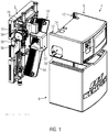
- the embodiment has a base plate 2 for wall mounting of the module shown, on which the essential components of the module are mounted.
- the base plate 2 can be covered with a two-part cover 4 consisting of an upper housing part 6 and a lower housing part 8.
- the base plate 2 and the cover 4 are made of a thermally insulating material, such as a foamed plastic. In the embodiment shown, these parts are made of expanded polypropylene (EPP).
- EPP expanded polypropylene
- the base plate 2 has at its longitudinal side edges projecting guide rails 10, which are integrally formed from the material of the EPP on the base plate 2 and together with guide grooves 12 of the cover 4 form a sliding guide, so that the lower housing part 8 from below and the upper housing part 6 from above the base plate 2 can be pushed and held it.
- housing upper part 6 and lower housing part 8 have on their adjacent side surfaces form-fitting elements which allow the edges of the parts 6, 8 to overlap, to connect them as closely as possible. This is intended to effect a good insulation of the housing formed by the base plate 2 and the two housing parts 6, 8.
- the pipe sections 20, 22 terminate via base plate 2 with a connection which is surrounded by a union nut and extends substantially perpendicular to the plane of the plate 2 base plate.
- the inlet pipe section 18 of the primary circuit is connected to a designated with reference numeral 26 propeller housing a generally designated by reference numeral 18 pump, which forms the water-bearing region of the pump 28.
- a further pipe section 30 is provided, whose outlet opening extends, surrounded by a union nut, substantially parallel to the plane of the base plate 2.
- a corresponding opening has the pipe section marked with reference numeral 32, which communicates with the inlet pipe section 24 of the secondary circuit SK with the interposition of a manual shut-off valve 34 and a motor-driven shut-off valve 36 with a drain opening 38 provided therebetween.
- the base plate 2 has at its longitudinal edges a plurality of indentations 40, which serve for wall mounting of the module. Furthermore, the base plate 2 integrally forms cable duct structures 42, which can, for example, lead and hold cables to the pump 28 and the motor of the motor-driven shut-off valve 36 and a temperature sensor 44 marked with reference numeral 44 and associated with the inlet pipe section 22 of the secondary circuit SK.
- the above-described tubes of the module are usually on the secondary side of gunmetal, stainless steel or drinking water approved plastics.
- the tubes of the primary circuit are usually made of gunmetal, stainless steel, gray cast iron or brass.
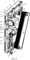
- the plate heat exchanger is usually a plate heat exchanger made of stainless steel, which is connected to the base plate 2 via holding plates 46, which are held in holders formed by the base plate 2.
- a a abcanplatte 48 is provided between the plate heat exchanger 14 and the motor-operated shut-off valve 36.
- the plate heat exchanger 14 is screwed via the union nuts with the associated pipe sections 20, 22, 30, 32 and accordingly fluidly connected to the primary circuit PK and the secondary circuit SK.
- the plate heat exchanger 14 is mounted obliquely relative to the predetermined by the longitudinal sides of the base plate 2 vertical extent, in the present case with an inclination angle of about 30 ° relative to the vertical.
- Reference numeral 52 denotes a pump housing, which is formed by a plastic molding.
- This plastic molding has frontally projecting locking pin 54 which engage in corresponding thereto on the base plate 2 formed locking recesses 56 to connect the Pumpeneinhausung 52 with the base plate 2 by plugging form-fitting manner.
- the pump housing 52 surrounds a motor 58 with a pump control provided thereon, not drawn in detail.
- a bottom 60 of the pump housing 52 (see. Fig. 3 ) is penetrated by an end portion of the motor 58 and partially by the propeller housing 26.
- One in the ground A passage opening 62 designed for this purpose is dimensioned such that these parts of the pump 28 are fitted into the floor 60.
- the connection between the bottom 60 and the pump 28 is ideally at least approximately fluid-tight here.
- the pump housing 52 forms an inlet opening 64.
- This inlet opening 64 is predetermined solely by the circumferential walls 66 of the pump housing 52.
- the motor 58 of the pump 28 is exposed in the inlet port 64 and is spaced from the inside surfaces of the peripheral walls 66 by all-round, which together with a bottom recess 68 formed on the base plate 2, define a cylindrical peripheral surface defining the motor 58 surrounds with distance.
- the upper circumferential wall 66 of the pump housing 52 is surmounted by a chimney segment 70, which is provided integrally on the pump housing 52 and defines an outlet opening 72, which is sealingly received in a chimney recess 74 of the housing upper part 6. From the base plate 2 projecting and formed by this positioning webs 76, which are provided in parallel and spaced from the upper edge of the base plate 2, fit the chimney segment 70 between them.
- the end faces of the circumferential walls 66 forming the inlet opening 64 are contoured for sealing engagement with a side wall of the housing upper part 6 and adjoin a lateral air inlet 78 which is recessed on a side wall of the housing upper part 6.
- the Kaminaus Principleung 74 surrounds the chimney segment 40 end, whereby an upper-side air outlet for the outflow of air from the pump housing 52 is formed by the cover 4.
- Identifiable longitudinal slots adjacent to the fireplace recess 74 enclose the pipe sections 18, 20 of the primary area PK in a substantially sealing manner.
- a corresponding embodiment is provided on the underside of the housing lower part 8 to provide passages for the pipe sections 22, 24 of the secondary region SK.
Landscapes
- Engineering & Computer Science (AREA)
- Physics & Mathematics (AREA)
- Thermal Sciences (AREA)
- Chemical & Material Sciences (AREA)
- Combustion & Propulsion (AREA)
- Mechanical Engineering (AREA)
- General Engineering & Computer Science (AREA)
- Heat-Exchange Devices With Radiators And Conduit Assemblies (AREA)
- Other Air-Conditioning Systems (AREA)
Claims (12)
- Module destiné au chauffage d'eau comprenant un échangeur de chaleur (14) présentant une zone primaire (PK) et une zone secondaire (SK), et une pompe (28), ces deux éléments étant recouverts par un capotage d'isolation thermique (4) d'un boitier (2, 4, 6, 8), caractérisé par une enceinte de confinement de pompe (52), qui est réalisée de manière indépendante du capotage d'isolation thermique (4) du boitier (2, 4, 6, 8) et est prévue dans le boitier (2, 4, 6, 8), et qui enferme au moins partiellement la pompe (28) en l'isolant sur le plan thermique par rapport à l'échangeur de chaleur (14), et est pourvue d'ouvertures d'entrée et de sortie (64 ; 72) communiquant avec l'environnement.
- Module selon la revendication 1, caractérisé en ce que l'enceinte de confinement de pompe (52) est réalisée par une pièce moulée de matière plastique.
- Module selon la revendication 1 ou la revendication 2, caractérisé en ce que l'enceinte de confinement de pompe (52) est réalisée par une pièce moulée de matière plastique sous forme de mousse.
- Module selon l'une des revendications précédentes, caractérisé en ce que l'enceinte de confinement de pompe (52) présente une ouverture de passage (62), qui est d'une configuration adaptée à faire traverser des parties de la pompe (28), et est traversée par la pompe (28) de façon telle, qu'une zone (26) véhiculant de l'eau, de la pompe (28), dépasse extérieurement de l'enceinte de confinement de pompe (52) .
- Module selon l'une des revendications précédentes, caractérisé en ce que l'enceinte de confinement de pompe (52) forme un tronçon de cheminée (70) menant à l'ouverture de sortie (72).
- Module selon l'une des revendications précédentes, caractérisé en ce que le capotage (4) possède une entrée d'air (78) latérale, qui communique avec l'ouverture d'entrée (64) de l'enceinte de confinement de pompe (52).
- Module selon l'une des revendications précédentes, caractérisé en ce que l'enceinte de confinement de pompe (52) est raccordée de manière sensiblement étanche à l'entrée d'air (78).
- Module selon l'une des revendications précédentes, caractérisé en ce que le capotage (4) possède, sur le côté supérieur, une sortie d'air (74) avec laquelle communique l'ouverture de sortie (72) de l'enceinte de confinement de pompe (52).
- Module selon l'une des revendications précédentes, caractérisé en ce que le boitier (4) est réalisé en au moins deux parties, et en ce qu'une partie supérieure de boitier (6), qui forme l'entrée d'air (78) et la sortie d'air (74), est appliquée de manière isolante sur le plan thermique, sur une partie inférieure de boitier (8) reliée à une plaque de base (2) du boitier (4).
- Module selon la revendication 8, caractérisé en ce que la plaque de base (2) forme en commun avec la partie supérieure de boitier (6), un guidage de coulissement (10, 12) pour monter la partie supérieure de boitier (6) sur la plaque de base (2), par coulissement.
- Module selon la revendication 8 ou la revendication 9, caractérisé en ce que la plaque de base (2) forme en commun avec la partie inférieure de boitier (8), un guidage de coulissement (10, 12) pour monter la partie inférieure de boitier (8) sur la plaque de base (2), par coulissement.
- Module selon l'une des revendications précédentes, caractérisé en ce que l'enceinte de confinement de pompe (52) est maintenue par complémentarité de formes sur la plaque de base (2).
Applications Claiming Priority (1)
| Application Number | Priority Date | Filing Date | Title |
|---|---|---|---|
| DE202015004260.0U DE202015004260U1 (de) | 2015-06-16 | 2015-06-16 | Modul zur Wassererwärmung |
Publications (2)
| Publication Number | Publication Date |
|---|---|
| EP3106765A1 EP3106765A1 (fr) | 2016-12-21 |
| EP3106765B1 true EP3106765B1 (fr) | 2018-12-05 |
Family
ID=56132822
Family Applications (1)
| Application Number | Title | Priority Date | Filing Date |
|---|---|---|---|
| EP16174629.2A Active EP3106765B1 (fr) | 2015-06-16 | 2016-06-15 | Module de chauffage d'eau |
Country Status (2)
| Country | Link |
|---|---|
| EP (1) | EP3106765B1 (fr) |
| DE (1) | DE202015004260U1 (fr) |
Families Citing this family (2)
| Publication number | Priority date | Publication date | Assignee | Title |
|---|---|---|---|---|
| GB2575652B (en) * | 2018-07-17 | 2021-07-14 | Vital Energi Utilities Ltd | Heat interface unit |
| DK181836B1 (en) * | 2023-02-03 | 2025-02-17 | Frese As | A district heating system cabinet with a locking mechanism comprising a lock bolt |
Family Cites Families (7)
| Publication number | Priority date | Publication date | Assignee | Title |
|---|---|---|---|---|
| DE4108910A1 (de) * | 1991-03-19 | 1992-10-22 | Oplaender Wilo Werk Gmbh | Vorrichtung zur versorgung einer fussbodenheizung |
| DE4425497C2 (de) * | 1994-07-19 | 1996-11-14 | Elco Kloeckner Heiztech Gmbh | Fördervorrichtung für einen Wärme- oder Kältekreislauf |
| DE19912284B4 (de) * | 1999-03-18 | 2012-10-18 | Grundfos A/S | Kompaktheizungsanlage |
| EP2093517B1 (fr) * | 2008-02-22 | 2014-01-15 | Grundfos Management A/S | Composant pour installation de chauffage compacte |
| DE102008033773A1 (de) * | 2008-07-18 | 2010-01-21 | Robert Bosch Gmbh | Gehäuse für ein Heizgerät und Heizgerät |
| DE202011003874U1 (de) * | 2011-03-11 | 2011-08-17 | Watts Industries Deutschland Gmbh | Wärmedämmvorrichtung für eine hydraulische Regelgruppe |
| DE202011104841U1 (de) * | 2011-08-25 | 2011-11-18 | Oventrop Gmbh & Co. Kg | Anordnung zur wärmedämmenden Installation von Armaturen oder Armaturengruppen |
-
2015
- 2015-06-16 DE DE202015004260.0U patent/DE202015004260U1/de not_active Expired - Lifetime
-
2016
- 2016-06-15 EP EP16174629.2A patent/EP3106765B1/fr active Active
Non-Patent Citations (1)
| Title |
|---|
| None * |
Also Published As
| Publication number | Publication date |
|---|---|
| EP3106765A1 (fr) | 2016-12-21 |
| DE202015004260U1 (de) | 2016-09-19 |
Similar Documents
| Publication | Publication Date | Title |
|---|---|---|
| EP2312224B1 (fr) | Pompe à chaleur dotée d'un module hydraulique | |
| EP2397777B1 (fr) | Unité de boîtier pour une installation de chauffage | |
| DE102012011032B4 (de) | Passiv gekühltes Instrumenten-Schutzgehäuse | |
| DE202009001056U1 (de) | Heizkreisverteiler | |
| EP1916486A2 (fr) | Système de collecte solaire | |
| EP3106765B1 (fr) | Module de chauffage d'eau | |
| DE60102417T2 (de) | Strahlplatte mit hoher Effizienz für Temperaturregulierung eines Raumes | |
| EP3712337B1 (fr) | Dispositif de circulation d'eau potable | |
| EP3098553B1 (fr) | Systeme d'echangeur thermique a plaques | |
| EP2498008B1 (fr) | Bâtiment | |
| EP0087733B1 (fr) | Groupe distributeur pour des installations de chauffage et/ou réfrigération fonctionnant par un agent caloporteur étant capable de circuler | |
| DE10041121B4 (de) | Wärmeübertrager mit mehreren Wärmeübertragungskreisen | |
| EP2957157B1 (fr) | Canal de câble et d'air combiné pour la climatisation d'une armoire de distribution et armoire de distribution correspondante | |
| DE19906180C2 (de) | Plattenwärmeübertrager für Warmwasserbereitung und -speicherung | |
| EP2175220B1 (fr) | Echangeur de chaleur à plaques et agencement composé d'un tel échangeur thermique à plaques et d'un chauffage à fluide | |
| EP1884723B1 (fr) | Module | |
| EP0905453B2 (fr) | Réchauffeur d'eau chaude sanitaire | |
| DE10340232A1 (de) | Kaminsystem | |
| EP3120095B1 (fr) | Échangeur de chaleur à plaques notamment pour appareil chauffant chauffé par combustible | |
| DE102010018086A1 (de) | Wärmeübertragungseinrichtung | |
| EP1789747B1 (fr) | Echangeur thermique | |
| EP2916077A1 (fr) | Radiateur | |
| DE102006020502A1 (de) | Anordnung eines Wärmetauscherelements | |
| DE8516442U1 (de) | Kühlvorrichtung für Klimaanlagen od. dgl. | |
| EP4481272A1 (fr) | Dispositif d'utilisation de la chaleur perdue de tuyaux de gaz de fumée |
Legal Events
| Date | Code | Title | Description |
|---|---|---|---|
| PUAI | Public reference made under article 153(3) epc to a published international application that has entered the european phase |
Free format text: ORIGINAL CODE: 0009012 |
|
| STAA | Information on the status of an ep patent application or granted ep patent |
Free format text: STATUS: THE APPLICATION HAS BEEN PUBLISHED |
|
| AK | Designated contracting states |
Kind code of ref document: A1 Designated state(s): AL AT BE BG CH CY CZ DE DK EE ES FI FR GB GR HR HU IE IS IT LI LT LU LV MC MK MT NL NO PL PT RO RS SE SI SK SM TR |
|
| AX | Request for extension of the european patent |
Extension state: BA ME |
|
| STAA | Information on the status of an ep patent application or granted ep patent |
Free format text: STATUS: REQUEST FOR EXAMINATION WAS MADE |
|
| 17P | Request for examination filed |
Effective date: 20161230 |
|
| RBV | Designated contracting states (corrected) |
Designated state(s): AL AT BE BG CH CY CZ DE DK EE ES FI FR GB GR HR HU IE IS IT LI LT LU LV MC MK MT NL NO PL PT RO RS SE SI SK SM TR |
|
| STAA | Information on the status of an ep patent application or granted ep patent |
Free format text: STATUS: EXAMINATION IS IN PROGRESS |
|
| 17Q | First examination report despatched |
Effective date: 20171113 |
|
| GRAP | Despatch of communication of intention to grant a patent |
Free format text: ORIGINAL CODE: EPIDOSNIGR1 |
|
| STAA | Information on the status of an ep patent application or granted ep patent |
Free format text: STATUS: GRANT OF PATENT IS INTENDED |
|
| INTG | Intention to grant announced |
Effective date: 20180810 |
|
| GRAS | Grant fee paid |
Free format text: ORIGINAL CODE: EPIDOSNIGR3 |
|
| GRAA | (expected) grant |
Free format text: ORIGINAL CODE: 0009210 |
|
| STAA | Information on the status of an ep patent application or granted ep patent |
Free format text: STATUS: THE PATENT HAS BEEN GRANTED |
|
| AK | Designated contracting states |
Kind code of ref document: B1 Designated state(s): AL AT BE BG CH CY CZ DE DK EE ES FI FR GB GR HR HU IE IS IT LI LT LU LV MC MK MT NL NO PL PT RO RS SE SI SK SM TR |
|
| REG | Reference to a national code |
Ref country code: GB Ref legal event code: FG4D Free format text: NOT ENGLISH |
|
| REG | Reference to a national code |
Ref country code: CH Ref legal event code: EP |
|
| REG | Reference to a national code |
Ref country code: AT Ref legal event code: REF Ref document number: 1073548 Country of ref document: AT Kind code of ref document: T Effective date: 20181215 |
|
| REG | Reference to a national code |
Ref country code: IE Ref legal event code: FG4D Free format text: LANGUAGE OF EP DOCUMENT: GERMAN |
|
| REG | Reference to a national code |
Ref country code: DE Ref legal event code: R096 Ref document number: 502016002673 Country of ref document: DE |
|
| REG | Reference to a national code |
Ref country code: CH Ref legal event code: NV Representative=s name: BOVARD AG PATENT- UND MARKENANWAELTE, CH |
|
| REG | Reference to a national code |
Ref country code: NL Ref legal event code: MP Effective date: 20181205 |
|
| REG | Reference to a national code |
Ref country code: LT Ref legal event code: MG4D |
|
| PG25 | Lapsed in a contracting state [announced via postgrant information from national office to epo] |
Ref country code: FI Free format text: LAPSE BECAUSE OF FAILURE TO SUBMIT A TRANSLATION OF THE DESCRIPTION OR TO PAY THE FEE WITHIN THE PRESCRIBED TIME-LIMIT Effective date: 20181205 Ref country code: NO Free format text: LAPSE BECAUSE OF FAILURE TO SUBMIT A TRANSLATION OF THE DESCRIPTION OR TO PAY THE FEE WITHIN THE PRESCRIBED TIME-LIMIT Effective date: 20190305 Ref country code: LV Free format text: LAPSE BECAUSE OF FAILURE TO SUBMIT A TRANSLATION OF THE DESCRIPTION OR TO PAY THE FEE WITHIN THE PRESCRIBED TIME-LIMIT Effective date: 20181205 Ref country code: LT Free format text: LAPSE BECAUSE OF FAILURE TO SUBMIT A TRANSLATION OF THE DESCRIPTION OR TO PAY THE FEE WITHIN THE PRESCRIBED TIME-LIMIT Effective date: 20181205 Ref country code: ES Free format text: LAPSE BECAUSE OF FAILURE TO SUBMIT A TRANSLATION OF THE DESCRIPTION OR TO PAY THE FEE WITHIN THE PRESCRIBED TIME-LIMIT Effective date: 20181205 Ref country code: BG Free format text: LAPSE BECAUSE OF FAILURE TO SUBMIT A TRANSLATION OF THE DESCRIPTION OR TO PAY THE FEE WITHIN THE PRESCRIBED TIME-LIMIT Effective date: 20190305 Ref country code: HR Free format text: LAPSE BECAUSE OF FAILURE TO SUBMIT A TRANSLATION OF THE DESCRIPTION OR TO PAY THE FEE WITHIN THE PRESCRIBED TIME-LIMIT Effective date: 20181205 |
|
| PG25 | Lapsed in a contracting state [announced via postgrant information from national office to epo] |
Ref country code: AL Free format text: LAPSE BECAUSE OF FAILURE TO SUBMIT A TRANSLATION OF THE DESCRIPTION OR TO PAY THE FEE WITHIN THE PRESCRIBED TIME-LIMIT Effective date: 20181205 Ref country code: SE Free format text: LAPSE BECAUSE OF FAILURE TO SUBMIT A TRANSLATION OF THE DESCRIPTION OR TO PAY THE FEE WITHIN THE PRESCRIBED TIME-LIMIT Effective date: 20181205 Ref country code: RS Free format text: LAPSE BECAUSE OF FAILURE TO SUBMIT A TRANSLATION OF THE DESCRIPTION OR TO PAY THE FEE WITHIN THE PRESCRIBED TIME-LIMIT Effective date: 20181205 Ref country code: GR Free format text: LAPSE BECAUSE OF FAILURE TO SUBMIT A TRANSLATION OF THE DESCRIPTION OR TO PAY THE FEE WITHIN THE PRESCRIBED TIME-LIMIT Effective date: 20190306 |
|
| PG25 | Lapsed in a contracting state [announced via postgrant information from national office to epo] |
Ref country code: NL Free format text: LAPSE BECAUSE OF FAILURE TO SUBMIT A TRANSLATION OF THE DESCRIPTION OR TO PAY THE FEE WITHIN THE PRESCRIBED TIME-LIMIT Effective date: 20181205 |
|
| PG25 | Lapsed in a contracting state [announced via postgrant information from national office to epo] |
Ref country code: CZ Free format text: LAPSE BECAUSE OF FAILURE TO SUBMIT A TRANSLATION OF THE DESCRIPTION OR TO PAY THE FEE WITHIN THE PRESCRIBED TIME-LIMIT Effective date: 20181205 Ref country code: PT Free format text: LAPSE BECAUSE OF FAILURE TO SUBMIT A TRANSLATION OF THE DESCRIPTION OR TO PAY THE FEE WITHIN THE PRESCRIBED TIME-LIMIT Effective date: 20190405 Ref country code: PL Free format text: LAPSE BECAUSE OF FAILURE TO SUBMIT A TRANSLATION OF THE DESCRIPTION OR TO PAY THE FEE WITHIN THE PRESCRIBED TIME-LIMIT Effective date: 20181205 Ref country code: IT Free format text: LAPSE BECAUSE OF FAILURE TO SUBMIT A TRANSLATION OF THE DESCRIPTION OR TO PAY THE FEE WITHIN THE PRESCRIBED TIME-LIMIT Effective date: 20181205 |
|
| PG25 | Lapsed in a contracting state [announced via postgrant information from national office to epo] |
Ref country code: EE Free format text: LAPSE BECAUSE OF FAILURE TO SUBMIT A TRANSLATION OF THE DESCRIPTION OR TO PAY THE FEE WITHIN THE PRESCRIBED TIME-LIMIT Effective date: 20181205 Ref country code: SM Free format text: LAPSE BECAUSE OF FAILURE TO SUBMIT A TRANSLATION OF THE DESCRIPTION OR TO PAY THE FEE WITHIN THE PRESCRIBED TIME-LIMIT Effective date: 20181205 Ref country code: IS Free format text: LAPSE BECAUSE OF FAILURE TO SUBMIT A TRANSLATION OF THE DESCRIPTION OR TO PAY THE FEE WITHIN THE PRESCRIBED TIME-LIMIT Effective date: 20190405 Ref country code: RO Free format text: LAPSE BECAUSE OF FAILURE TO SUBMIT A TRANSLATION OF THE DESCRIPTION OR TO PAY THE FEE WITHIN THE PRESCRIBED TIME-LIMIT Effective date: 20181205 Ref country code: SK Free format text: LAPSE BECAUSE OF FAILURE TO SUBMIT A TRANSLATION OF THE DESCRIPTION OR TO PAY THE FEE WITHIN THE PRESCRIBED TIME-LIMIT Effective date: 20181205 |
|
| REG | Reference to a national code |
Ref country code: DE Ref legal event code: R097 Ref document number: 502016002673 Country of ref document: DE |
|
| PLBE | No opposition filed within time limit |
Free format text: ORIGINAL CODE: 0009261 |
|
| STAA | Information on the status of an ep patent application or granted ep patent |
Free format text: STATUS: NO OPPOSITION FILED WITHIN TIME LIMIT |
|
| PG25 | Lapsed in a contracting state [announced via postgrant information from national office to epo] |
Ref country code: DK Free format text: LAPSE BECAUSE OF FAILURE TO SUBMIT A TRANSLATION OF THE DESCRIPTION OR TO PAY THE FEE WITHIN THE PRESCRIBED TIME-LIMIT Effective date: 20181205 Ref country code: SI Free format text: LAPSE BECAUSE OF FAILURE TO SUBMIT A TRANSLATION OF THE DESCRIPTION OR TO PAY THE FEE WITHIN THE PRESCRIBED TIME-LIMIT Effective date: 20181205 |
|
| 26N | No opposition filed |
Effective date: 20190906 |
|
| PG25 | Lapsed in a contracting state [announced via postgrant information from national office to epo] |
Ref country code: MC Free format text: LAPSE BECAUSE OF FAILURE TO SUBMIT A TRANSLATION OF THE DESCRIPTION OR TO PAY THE FEE WITHIN THE PRESCRIBED TIME-LIMIT Effective date: 20181205 |
|
| REG | Reference to a national code |
Ref country code: BE Ref legal event code: MM Effective date: 20190630 |
|
| PG25 | Lapsed in a contracting state [announced via postgrant information from national office to epo] |
Ref country code: TR Free format text: LAPSE BECAUSE OF FAILURE TO SUBMIT A TRANSLATION OF THE DESCRIPTION OR TO PAY THE FEE WITHIN THE PRESCRIBED TIME-LIMIT Effective date: 20181205 |
|
| PG25 | Lapsed in a contracting state [announced via postgrant information from national office to epo] |
Ref country code: IE Free format text: LAPSE BECAUSE OF NON-PAYMENT OF DUE FEES Effective date: 20190615 |
|
| PG25 | Lapsed in a contracting state [announced via postgrant information from national office to epo] |
Ref country code: BE Free format text: LAPSE BECAUSE OF NON-PAYMENT OF DUE FEES Effective date: 20190630 Ref country code: LU Free format text: LAPSE BECAUSE OF NON-PAYMENT OF DUE FEES Effective date: 20190615 |
|
| PG25 | Lapsed in a contracting state [announced via postgrant information from national office to epo] |
Ref country code: FR Free format text: LAPSE BECAUSE OF NON-PAYMENT OF DUE FEES Effective date: 20190630 |
|
| GBPC | Gb: european patent ceased through non-payment of renewal fee |
Effective date: 20200615 |
|
| PG25 | Lapsed in a contracting state [announced via postgrant information from national office to epo] |
Ref country code: GB Free format text: LAPSE BECAUSE OF NON-PAYMENT OF DUE FEES Effective date: 20200615 |
|
| PG25 | Lapsed in a contracting state [announced via postgrant information from national office to epo] |
Ref country code: CY Free format text: LAPSE BECAUSE OF FAILURE TO SUBMIT A TRANSLATION OF THE DESCRIPTION OR TO PAY THE FEE WITHIN THE PRESCRIBED TIME-LIMIT Effective date: 20181205 |
|
| PG25 | Lapsed in a contracting state [announced via postgrant information from national office to epo] |
Ref country code: HU Free format text: LAPSE BECAUSE OF FAILURE TO SUBMIT A TRANSLATION OF THE DESCRIPTION OR TO PAY THE FEE WITHIN THE PRESCRIBED TIME-LIMIT; INVALID AB INITIO Effective date: 20160615 Ref country code: MT Free format text: LAPSE BECAUSE OF FAILURE TO SUBMIT A TRANSLATION OF THE DESCRIPTION OR TO PAY THE FEE WITHIN THE PRESCRIBED TIME-LIMIT Effective date: 20181205 |
|
| PG25 | Lapsed in a contracting state [announced via postgrant information from national office to epo] |
Ref country code: MK Free format text: LAPSE BECAUSE OF FAILURE TO SUBMIT A TRANSLATION OF THE DESCRIPTION OR TO PAY THE FEE WITHIN THE PRESCRIBED TIME-LIMIT Effective date: 20181205 |
|
| P01 | Opt-out of the competence of the unified patent court (upc) registered |
Effective date: 20240304 |
|
| PGFP | Annual fee paid to national office [announced via postgrant information from national office to epo] |
Ref country code: DE Payment date: 20250626 Year of fee payment: 10 |
|
| PGFP | Annual fee paid to national office [announced via postgrant information from national office to epo] |
Ref country code: AT Payment date: 20250618 Year of fee payment: 10 |
|
| PGFP | Annual fee paid to national office [announced via postgrant information from national office to epo] |
Ref country code: CH Payment date: 20250701 Year of fee payment: 10 |