EP3106787B1 - Eisherstellungsvorrichtung und verfahren zur herstellung von eis - Google Patents
Eisherstellungsvorrichtung und verfahren zur herstellung von eis Download PDFInfo
- Publication number
- EP3106787B1 EP3106787B1 EP15186852.8A EP15186852A EP3106787B1 EP 3106787 B1 EP3106787 B1 EP 3106787B1 EP 15186852 A EP15186852 A EP 15186852A EP 3106787 B1 EP3106787 B1 EP 3106787B1
- Authority
- EP
- European Patent Office
- Prior art keywords
- ice
- water supply
- making
- water
- tray
- Prior art date
- Legal status (The legal status is an assumption and is not a legal conclusion. Google has not performed a legal analysis and makes no representation as to the accuracy of the status listed.)
- Not-in-force
Links
- 238000000034 method Methods 0.000 title claims description 27
- XLYOFNOQVPJJNP-UHFFFAOYSA-N water Substances O XLYOFNOQVPJJNP-UHFFFAOYSA-N 0.000 claims description 141
- 238000001816 cooling Methods 0.000 claims description 30
- 238000005192 partition Methods 0.000 claims description 12
- 238000010438 heat treatment Methods 0.000 claims description 6
- 239000010935 stainless steel Substances 0.000 claims description 5
- 229910001220 stainless steel Inorganic materials 0.000 claims description 5
- 239000008400 supply water Substances 0.000 claims description 5
- RYGMFSIKBFXOCR-UHFFFAOYSA-N Copper Chemical compound [Cu] RYGMFSIKBFXOCR-UHFFFAOYSA-N 0.000 claims description 4
- 229910000881 Cu alloy Inorganic materials 0.000 claims description 4
- 229910052802 copper Inorganic materials 0.000 claims description 4
- 239000010949 copper Substances 0.000 claims description 4
- 239000007769 metal material Substances 0.000 claims description 3
- 239000000463 material Substances 0.000 claims description 2
- 230000008014 freezing Effects 0.000 description 16
- 238000007710 freezing Methods 0.000 description 16
- 238000004519 manufacturing process Methods 0.000 description 8
- 230000009471 action Effects 0.000 description 6
- 229910052782 aluminium Inorganic materials 0.000 description 5
- XAGFODPZIPBFFR-UHFFFAOYSA-N aluminium Chemical compound [Al] XAGFODPZIPBFFR-UHFFFAOYSA-N 0.000 description 5
- 238000005520 cutting process Methods 0.000 description 4
- 229910052751 metal Inorganic materials 0.000 description 4
- 239000002184 metal Substances 0.000 description 4
- 238000003860 storage Methods 0.000 description 4
- 238000001746 injection moulding Methods 0.000 description 3
- 238000004140 cleaning Methods 0.000 description 2
- 238000003825 pressing Methods 0.000 description 2
- 239000003507 refrigerant Substances 0.000 description 2
- 229910001369 Brass Inorganic materials 0.000 description 1
- 230000000844 anti-bacterial effect Effects 0.000 description 1
- 230000004888 barrier function Effects 0.000 description 1
- 230000008901 benefit Effects 0.000 description 1
- 239000010951 brass Substances 0.000 description 1
- 230000006835 compression Effects 0.000 description 1
- 238000007906 compression Methods 0.000 description 1
- 238000009833 condensation Methods 0.000 description 1
- 230000005494 condensation Effects 0.000 description 1
- 238000005260 corrosion Methods 0.000 description 1
- 230000007797 corrosion Effects 0.000 description 1
- 230000007423 decrease Effects 0.000 description 1
- 238000009826 distribution Methods 0.000 description 1
- 230000000694 effects Effects 0.000 description 1
- 230000008020 evaporation Effects 0.000 description 1
- 238000001704 evaporation Methods 0.000 description 1
- 238000002844 melting Methods 0.000 description 1
- 230000008018 melting Effects 0.000 description 1
- 238000012986 modification Methods 0.000 description 1
- 230000004048 modification Effects 0.000 description 1
- 238000012805 post-processing Methods 0.000 description 1
- 230000008569 process Effects 0.000 description 1
- 230000000717 retained effect Effects 0.000 description 1
- 239000007921 spray Substances 0.000 description 1
- 239000000126 substance Substances 0.000 description 1
- 239000008399 tap water Substances 0.000 description 1
- 235000020679 tap water Nutrition 0.000 description 1
Images



Classifications
-
- F—MECHANICAL ENGINEERING; LIGHTING; HEATING; WEAPONS; BLASTING
- F25—REFRIGERATION OR COOLING; COMBINED HEATING AND REFRIGERATION SYSTEMS; HEAT PUMP SYSTEMS; MANUFACTURE OR STORAGE OF ICE; LIQUEFACTION SOLIDIFICATION OF GASES
- F25C—PRODUCING, WORKING OR HANDLING ICE
- F25C1/00—Producing ice
- F25C1/22—Construction of moulds; Filling devices for moulds
- F25C1/25—Filling devices for moulds
-
- F—MECHANICAL ENGINEERING; LIGHTING; HEATING; WEAPONS; BLASTING
- F25—REFRIGERATION OR COOLING; COMBINED HEATING AND REFRIGERATION SYSTEMS; HEAT PUMP SYSTEMS; MANUFACTURE OR STORAGE OF ICE; LIQUEFACTION SOLIDIFICATION OF GASES
- F25C—PRODUCING, WORKING OR HANDLING ICE
- F25C1/00—Producing ice
- F25C1/22—Construction of moulds; Filling devices for moulds
- F25C1/24—Construction of moulds; Filling devices for moulds for refrigerators, e.g. freezing trays
-
- F—MECHANICAL ENGINEERING; LIGHTING; HEATING; WEAPONS; BLASTING
- F25—REFRIGERATION OR COOLING; COMBINED HEATING AND REFRIGERATION SYSTEMS; HEAT PUMP SYSTEMS; MANUFACTURE OR STORAGE OF ICE; LIQUEFACTION SOLIDIFICATION OF GASES
- F25C—PRODUCING, WORKING OR HANDLING ICE
- F25C2500/00—Problems to be solved
- F25C2500/02—Geometry problems
Definitions
- the present disclosure relates to a method of producing ice with an ice-making device and said ice-making device.
- a refrigerator is an apparatus for storing food at a relatively low temperature and may be configured to store food in a frozen state or a refrigerated state.
- a decision to store food in a frozen state or refrigerated state may depend on the kind of food to be stored.
- the interior of the refrigerator is cooled by supplied cold air, in which the cold air is typically generated by a temperature exchange action of a refrigerant according to a cooling cycle including compression, condensation, expansion and evaporation.
- the cold air supplied to the inside of the refrigerator can be distributed in the refrigerator by convection.
- items within the refrigerator can be stored at a desired temperature.
- a refrigerator typically includes a main body having a rectangular parallelepiped shape with an open front side.
- a refrigerating compartment e.g.; refrigerating space, portion, room, etc.
- a freezing compartment e.g.: freezing space, portion, room, etc.
- a refrigerating compartment door and a freezing compartment door for selectively closing and opening the refrigerator compartment and the freezing compartment may be provided on the front side or surface of the main body.
- a plurality of drawers, shelves and container boxes for storing different kinds of food in a desired state may be provided in the internal storage spaces of the refrigerating compartment and freezing compartment.
- mainstream refrigerators are top-mount-type refrigerators having a freezing compartment positioned at an upper side or portion of the refrigerator and a refrigerating compartment positioned at the lower side or portion of the refrigerator.
- bottom-freeze-type refrigerators can enhance user convenience in which a more frequently-used refrigerating compartment is positioned at an upper portion of the refrigerator and a less frequently used freezing compartment is positioned at a lower portion of the refrigerator. This provides an advantage in that a user can conveniently use the refrigerating compartment.
- the bottom-freeze-type refrigerators in which the freezing compartment is positioned at the lower portion or side
- the freezing compartment door e.g., to take out pieces of ice, food, etc.
- the ice-making device may include an ice-making assembly provided with an ice tray for producing pieces of ice (e.g., in various shapes including cubes, cylindrical, semi-spherical, etc.), an ice bucket which stores the pieces of ice, and a feeder assembly which feeds the pieces of ice stored in the ice bucket to the dispenser.
- an ice-making assembly provided with an ice tray for producing pieces of ice (e.g., in various shapes including cubes, cylindrical, semi-spherical, etc.)
- an ice bucket which stores the pieces of ice
- a feeder assembly which feeds the pieces of ice stored in the ice bucket to the dispenser.
- a plurality of ice-making spaces capable of retaining water are formed on the upper surface of a tray body.
- a water supply port capable of distributing water to the ice-making spaces is formed on one surface of the tray body.
- Water distribution grooves are formed between the ice-making spaces.
- the ice-making spaces are connected to one another in a manner that allows water to flow between the ice-making spaces. Accordingly water supplied through the water supply port is supplied to one of the ice-making spaces and is distributed to the next ice-making space through each of the water supply grooves. As a result, the ice-making spaces are supplied with water.
- a cutting unit for cutting the single mass into individual pieces of ice is typically provided in the ice-making device.
- the size and shape of the resulting pieces of ice or ice cubes may not be uniform.
- conventional ice trays are typically manufactured by a method of melting and injecting aluminum.
- the strength and mechanical properties of a product can typically only be maintained when the thickness of aluminum is about 2 mm or more.
- the thickness of the ice tray increases, there is a potential problem in that the heat exchange rate of the ice tray decreases.
- the aluminum injection molding method suffers from a problem in that the post-processing process is complex and the cleaning is difficult to perform.
- the document US 2013/291582 A1 discloses an ice tray often ice making device comprising a tray body with ice making spaces retaining water and a plurality of partition walls extending upward from the bottom surface of the tray body defining a plurality of independent ice making spaces.
- the tray body and the partition walls are made of metallic material and are manufactured by a press work at one time.
- the ice-making device comprises a case including a cooling space defined therein, a cooling unit configured to cool the cooling space, and an ice-making assembly disposed in the cooling space and configured to produce pieces of ice.
- the ice-making assembly includes an ice tray having a plurality of independently-defined ice-making spaces and a water supply unit configured to supply water to the ice-making spaces.
- the ice tray can be manufactured by pressing a metal at one time.
- the water supply unit comprises a feeder pipe configured to feed water to the ice-making assembly, and a water supply pipe connected to the feeder pipe and disposed above the ice tray to extend along, the water supply pipe includes a plurality of water supply holes formed in positions corresponding to the ice-making spaces so that water is supplied to the respective ice-making spaces through the respective water supply holes.
- the diameter of the water supply holes grows larger as the water supply holes are positioned farther away from the feeder pipe.
- a heater configured to heat the water supply pipe can be provided on the water supply pipe in such a fashion as to surround an outer circumference of the water supply pipe.
- a heater waterproof member configured to prevent the heater from making contact with water can be provided outside the heater in such a fashion as to surround the heater and the outer circumference of the water supply pipe.
- the ice tray of an ice-making device can comprise: a tray body configured to provide ice-making spaces that retain water; and a plurality of partition walls extending upward from a bottom surface of the tray body and configured to define the ice-making spaces as a plurality of independent ice-making spaces, wherein the tray body and the partition walls are made of a metallic material and are manufactured by a press work at one time.
- the tray body and the partition walls can be made of a material selected from a group consisting of stainless steel, copper and copper alloy.
- a method of producing ice comprises: filling an ice tray with water from a feeder pipe that has holes aligned to ice making spaces of the ice tray; supplying cold air to the ice tray and water; and ejecting resulting pieces of ice from the ice tray.
- the method further comprises supplying the water from the feeder pipe to a water supply pipe.
- an amount of water supplied to the ice-making spaces becomes uniform.
- the method can also include heating the feeder pipe and water supply pipe to prevent ice clogging the respective feeder pipe and water supply pipe.
- a heater waterproof member can be used to reduce moisture contact with a heater.
- the ice tray can also be heated to facilitate release of the piece of ice.
- FIG. 1 is a perspective view of an ice tray according to one aspect of the present disclosure.
- the ice tray 10 provides ice-making spaces 13 in which water is phase-transformed into pieces of ice.
- the shape of the pieces of ice produced in the ice-making spaces 13 may correspond to the shape of the ice-making spaces 13.
- the ice tray 10 includes a tray body 11 having an upper surface on which a plurality of ice-making spaces 13 for retaining water are formed, and a plurality of partition walls 12 extending in an up-down direction from a bottom surface of the tray body 11.
- the partition walls 12 are disposed between the ice-making spaces 13 to define the ice-making spaces 13 as a separate independent spaces.
- the conventional water supply grooves interconnecting a plurality of ice-making spaces are omitted.
- the ice-making spaces 13 may have variety of different shapes, such as the illustrated shape, a cube, a cylinder, a star shape, a heart shape, and so on.
- the ice tray 10 may include cooling ribs for increasing the contact area of the ice tray 10 with the cold air.
- the ice tray 10, namely the tray body 11 and the partition walls 12, may be manufactured by pressing a metal such as stainless steel, copper or copper alloy. Since the ice tray 10 has a simple structure in which the ice-making spaces 13 are formed on the upper surface of the tray body 11, it is possible to manufacture the ice tray 10 by a press work method. In the case where the ice tray 10 is manufactured by the press work method, it is possible to simplify a manufacturing process and consequently improve productivity while reducing manufacturing cost. Furthermore, the cleaning is easy to perform because the ice tray 10 has a simple structure.
- the press work method is capable of manufacturing a metal product at a relatively small thickness. Accordingly, the ice tray 10 having a relatively small thickness is capable of rapidly transferring the energy of the cold air to the water in the ice-making spaces 13. Furthermore, since the amount of a metal used to manufacture the ice tray 10 is reduced, it is possible to save on manufacturing cost. If stainless steel, copper or copper alloy having a high elongation is used (instead of difficult-to-process aluminum having a low elongation) it is possible to easily perform the press work.
- the ice tray 10 is made of stainless steel having a relatively high corrosion resistance or brass having an anti-bacterial effect, the pieces of ice produced by the ice tray 10 is less harmful to a human body than the pieces of ice produced by an ice tray made of aluminum containing a substance harmful to a human body.
- An ice-making device for a refrigerator which includes an ice tray according to one embodiment of the present invention.
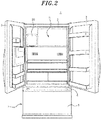
- FIG. 2 is a front view of a refrigerator provided with an ice-making device including the ice tray illustrated in FIG. 1 .
- FIG. 3 is an exploded perspective view of the ice-making device provided in the refrigerator illustrated in FIG. 2 .
- FIG. 4 is a side sectional view of the ice-making device illustrated in FIG. 3 .
- the ice-making device 20 including the ice tray 10 according to one embodiment, is capable of uniformly supplying water to the ice-making spaces 13 of the ice tray 10.
- the ice-making device 20 includes a case 100, a cooling unit (not illustrated) configured to cool the interior of the case 100, an ice-making assembly 200 to which the ice tray 10 is mounted, an ice bucket 320 in which pieces of ice produced in the ice tray 10 are stored, and a feeder assembly 400 configured to feed the pieces of ice from the ice bucket 320.
- the refrigerator 1 is an example of a refrigerator that includes a main body 2 which constitutes an outer shell, a barrier 4 which divides food storage spaces (e.g., compartments, portions, rooms, etc.) formed within the main body 2.
- One food storage space includes an upper refrigerating compartment R and another food storage space includes a lower freezing compartment F.
- Refrigerating compartment doors 3 are provided on the opposite edges of the front surface of the main body 2 and configured to selectively open and close the refrigerating compartment R by the rotational movement of the refrigerating space doors 3.
- Freezing compartment door 5 is configured to open and close the front opening portion of the freezing compartment F by the movement of the freezing compartment door 5.
- an ice-making device 20 is provided in a region on one side of the upper portion of the refrigerating compartment R.
- the ice-making device 20 may be installed in other positions of the refrigerating compartment R or in one of the refrigerating compartment doors 3.
- ice-making device 20 may also be installed in freezing compartment F.
- a cooling space 105 including ice tray 10 in which pieces of ice can be produced is formed within the case 100.
- the ice-making assembly 200 may be disposed at the upper side within the cooling space 105.
- the cooling unit is used to cool the cooling space 105.
- the cooling unit can cool the ice tray 10 by generating a cold air and supplying the generated cold air to the ice tray 10, or by bringing a cooling pipe (e.g., which feeds a low-temperature refrigerant) into contact with the lower side of the ice tray 10.
- the cooling unit may include a compressor, a condenser, an expansion valve and an evaporator, which constitute a cooling cycle.
- the cold air may be supplied by a blower or the like to the ice tray 10 via an ejection duct 310 and a cold air guide unit 220. In one embodiment, the cold air is supplied to the cooling space 105.
- the ice-making assembly 200 includes an ice tray 10, a water supply unit 210 configured to supply water to the ice tray 10, a cold air guide unit 220 configured to guide the flow of the cold air so that the cold air supplied from the cooling unit moves along the lower surface of the ice tray 10, and a rotary unit 230 configured to drop the pieces of ice produced in the ice tray 10 into the ice bucket 320 disposed below the ice tray 10.
- FIG. 5 illustrates one embodiment of a structure by which water is supplied according to the invention to the ice tray of the ice-making device illustrated in FIG. 4 .
- the water supply unit 210 is configured to supply water to the ice tray 10.
- the water supply unit 210 includes a feeder pipe 211 coupled to water supply pipe 212.
- the feeder pipe 211 is coupled to a water supply (e.g., supply tank, a tap water pipeline, etc.) and is configured to feed water to the ice-making assembly 200.
- the water supply pipe 212 is disposed above the ice tray 10 to extend along the longitudinal direction of the ice tray 10.
- a plurality of water supply holes 215 are formed in the water supply pipe 212 in positions corresponding to the ice-making spaces 13 so that water can be supplied to the ice-making spaces 13 through the water supply holes 215.
- a heater 213 for preventing freeze and rupture of the feeder pipe 211 and the water supply pipe 212 may be coupled to the feeder pipe 211 in such a fashion that the heater 213 surrounds the outer circumference of the feeder pipe 211 and the water supply pipe 212. Furthermore, a heater waterproof member 214 is provided outside the heater 213 in such a fashion as to surround the outer circumference of the feeder pipe 211 and the water supply pipe 212. This makes it possible to isolate the heater 213 from moisture, thereby preventing an accident such as a short circuit or the like.
- the diameter of the water supply holes 215 is set to grow larger as the water supply holes 215 are positioned farther away from the feeder pipe 211.
- Water supplied through the feeder pipe 211 flows along the water supply pipe 212.
- the water is first supplied to the water supply holes 215 positioned closer to the feeder pipe 211 and is then supplied to the water supply holes 215 positioned farther from the feeder pipe 211. If the water supply holes 215 would be equal in diameter to one another, a larger amount of water would be supplied to the water supply holes 215 positioned closer to the feeder pipe 211. That is to say, the amount of water supplied to the ice-making spaces 13 of the ice tray 10 may not be uniform.
- the diameter of the water supply holes 215 is set to grow larger as the water supply holes 215 are positioned farther away from the feeder pipe 211, the amount of water supplied to the ice-making spaces 13 can become uniform.
- the diameter of the water supply holes 215 may be set in view of the volume of the ice-making spaces 13, the amount and pressure of the water supplied from the feeder pipe 211 and the water supply pipe 212, the length of the water supply pipe 212, etc.
- the cold air guide unit 220 has a function of guiding the cold air supplied from the cooling unit toward the lower side of the ice tray 10.
- the cold air guide unit 220 may be coupled to the ejection duct 310 which is a path through which the cold air is supplied from the cooling unit.
- the cold air guide unit 220 may include cold air guide members 221 and 222 which are coupled to at least one surface of the ejection duct 310. As illustrated in FIG. 4 , the cold air guide unit 220 may include a first cold air guide member 221 extending from the upper surface of the ejection duct 310 and a second cold air guide member 222 extending from the lower surface of the ejection duct 310.
- the cold air guided by the cold air guide members 221 and 222 can move toward the lower surface of the ice tray 10. As the cold air exchanges heat with the ice tray 10, the water in the ice tray 10 is phase-transformed into pieces of ice.
- the rotary unit 230 may include a motor 232, a rotation shaft 231 coupled to the ice tray 10 and rotated by the motor 232, and a motor housing 233 configured to accommodate the motor 232 therein.
- the pieces of ice thus produced may be dropped by the rotary unit 230 into the ice bucket 320 disposed below the ice tray 10.
- the ice tray 10 may be rotated so that the upper surface of the ice tray 10 faces toward the ice bucket 320. If the ice tray 10 is rotated at a specific angle or more, the ice tray 10 is twisted by an interference member (not illustrated). Due to this twisting action, the pieces of ice accommodated in the ice tray 10 may be dropped into the ice bucket 320.
- a plurality of ejectors may be provided along the longitudinal direction of the rotation shaft 231.
- the ice tray 10 is not rotated and the pieces of ice may be taken out from the ice tray 10 by the rotation of the ejectors of the rotation shaft 231.
- an ice release heater 240 may be provided in the ice tray 10 so that the ice release heater 240 can heat the ice tray 10 during or prior to the rotation of the rotation shaft 231. By the heating action of the ice release heater 240, the surfaces of the pieces of ice accommodated in the ice tray 10 are melted and separated from the ice tray 10.
- the feeder assembly 400 may include an auger 410 and an auger motor 420 which are configured to feed the pieces of ice toward an ejection part 600.
- the auger 410 may be a rotating member having a screw or a spiral blade.
- the auger 410 is rotated by the auger motor 420.
- the auger 410 is disposed within the ice bucket 320.
- the pieces of ice stacked in the ice bucket 320 may be inserted into the groove defined by the screw or the blade and may be fed toward the ejection part 600.
- the auger motor 420 may be accommodated within an auger motor housing 430.
- the ejection part 600 may be coupled to a dispenser (not illustrated) provided in one of the refrigerating compartment doors 3. Depending on the user's choice, the pieces of ice fed by the feeder assembly 400 may be dispensed to a user through the dispenser.
- water is uniformly supplied to the ice-making spaces 13 of the ice tray 10 through the water supply unit 210.
- water fed through the feeder pipe 211 is moved along the longitudinal direction of the water supply pipe 212 and is dropped through the water supply holes 215 of the water supply pipe 212 into the ice-making spaces 13 disposed below the water supply pipe 212.
- the diameter of the water supply holes 215 grows larger as the water supply holes 215 are positioned farther away from the feeder pipe 211. Therefore, the amount of water supplied within a unit time through the water supply holes 215 positioned farther away from the feeder pipe 211 is more than the amount of water supplied within a unit time through the water supply holes 215 positioned closer to the feeder pipe 211.
- the amounts of water supplied to the respective ice-making spaces 13 can become uniform.
- the cold air generated by the actions of the compressor, the condenser, the expansion valve and the evaporator of the cooling unit is supplied to the cooling space 105 through the ejection duct 310.
- the supplied cold air may freeze the water contained in the ice tray 10 disposed within the cooling space 105.
- the cold air moves along the lower surface of the ice tray 10 and exchanges heat with the lower surface of the ice tray 10, thereby freezing the water in the ice tray 10 into pieces of ice.
- the heater 213 is coupled to the feeder pipe 211 and the water supply pipe 212, it is possible to prevent the feeder pipe 211 and the water supply pipe 212 from being frozen and ruptured by the cold air.
- the heater waterproof member 214 prevents the heater 213 from making contact with water. It is therefore possible to prevent occurrence of a short circuit accident.
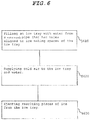
- FIG. 6 is a flowchart illustrating a method of making ice (e.g., in an ice tray illustrated in FIG. 2 , etc.).
- a method of producing ice comprises: filling an ice tray with water from a water supply pipe that has holes aligned to ice making spaces of the ice tray (e.g., S610); supplying cold air to the ice tray and water (e.g., S620); and ejecting resulting pieces of ice from the ice tray (e.g., S630).
- the method further comprises supplying the water from the feeder pipe to a water supply pipe.
- an amount of water supplied to the ice-making spaces becomes uniform.
- the method can also include heating the feeder pipe and water supply pipe to prevent ice clogging the respective feeder pipe and water supply pipe.
- a heater waterproof member can be used to reduce moisture contact with a heater.
- the ice tray can also be heated to facilitate release of the piece of ice.
- the pieces of ice in the ice-making spaces 13 independently defined by the partition walls 12 may have the form of individually-separated pieces of ice or cubes.
- the surfaces of the pieces of ice produced in the ice tray 10 are melted by the heating action of the ice release heater 240. As a result, the pieces of ice are easily separated from the ice tray 10. Thereafter, due to the rotation of the rotation shaft 231, the pieces of ice are dropped down and are staked in the ice bucket 320.
- the pieces of ice produced in the ice-making device 20 of the refrigerator including the ice tray 10 according to the present embodiment have an individually-separated form.
- the shape of the pieces of ice may be completely identical with the shape of the ice-making spaces 13, the outward appearance of the pieces of ice is considered pleasing or beautiful. This makes it possible to produce pieces of ice in different shapes such as a star shape, a heart shape or the like.
- water is supplied to the respective ice-making spaces 13 by the water supply unit 210.
- the amounts of water supplied to the respective ice-making spaces 13 is uniform.
Landscapes
- Engineering & Computer Science (AREA)
- Physics & Mathematics (AREA)
- Mechanical Engineering (AREA)
- Thermal Sciences (AREA)
- General Engineering & Computer Science (AREA)
- Devices That Are Associated With Refrigeration Equipment (AREA)
- Chemical & Material Sciences (AREA)
- Combustion & Propulsion (AREA)
- Cold Air Circulating Systems And Constructional Details In Refrigerators (AREA)
Claims (10)
- Ein Verfahren zur Herstellung von Eis für eine Eis-Herstellungsvorrichtung (20) umfassend ein Gehäuse (100) mit einem darin gebildeten Kühlraum (105), einer Kühleinheit zum Kühlen des Kühlraums (105) sowie ein in dem Kühlraum (105) angeordnetes Eis-Herstellungsaggregat (200) zum Herstellen von Eisstücken,
wobei das Eis-Herstellungsaggregat (200) eine Eisschale (10) mit einer Vielzahl von unabhängig voneinander gebildeten Eis-Herstellungsräumen (13) sowie eine Wasser-Versorgungseinheit (210) umfasst, die dazu dient, die Eis-Herstellungsräume (13) mit Wasser zu versorgen,
wobei die Wasser-Versorgungseinheit (210) ein Zuflussrohr (211) umfasst, über das Wasser in das Eis-Herstellungsaggregat (200) und in ein mit dem Zuflussrohr (211) gekoppeltes und oberhalb der Eisschale (10) angeordnetes Wasser-Versorgungsrohr (212) geleitet werden kann, wobei das Wasser-Versorgungsrohr (212) eine Vielzahl von Wasser-Versorgungsöffnungen (215), die an den Eis-Herstellungsräumen (13) entsprechenden Positionen ausgebildet sind, so dass die jeweiligen Eis-Herstellungsräume (13) durch die jeweiligen Wasser-Versorgungsöffnungen (215) mit Wasser versorgt werden, und
wobei das Verfahren umfasst:Befüllen der Eisschale (10) mit Wasser aus dem Zuflussrohr (211),Zuführen von kalter Luft zu der mit dem Wasser gefüllten Eisschale (10), undAuswerfen von entstandenen Eisstücken aus der Eisschale (10),dadurch gekennzeichnet, dass
das Verfahren ferner umfasst, dass ein Durchmesser der Wasser-Versorgungsöffnungen (215) umso größer wird, je weiter die Wasser-Versorgungsöffnungen (215) von dem Zuflussrohr (211) entfernt sind. - Das Verfahren gemäß Anspruch 1, ferner umfassend ein Erwärmen des Zuflussrohrs (211) und des Wasser-Versorgungsrohrs (212), um ein Zusetzen des Zuflussrohrs (211) bzw. des Wasser-Versorgungsrohrs (212) mit Eis zu verhindern.
- Das Verfahren gemäß Anspruch 1, ferner umfassend die Verwendung eines wasserfesten Heizvorrichtungs-Elements (214) zum Reduzieren eines Feuchtigkeitskontakts mit einer Heizvorrichtung (213).
- Das Verfahren gemäß Anspruch 1, ferner umfassend ein Erwärmen der Eisschale (10) für ein leichteres Abgeben der Eisstücke.
- Eine Eis-Herstellungsvorrichtung (20) umfassend:ein Gehäuse (100) mit einem darin gebildeten Kühlraum (105),eine Kühleinheit zum Kühlen des Kühlraums (105), undein in dem Kühlraum (105) angeordnetes Eis-Herstellungsaggregat (200) zur Herstellung von Eisstücken,wobei das Eis-Herstellungsaggregat (200) eine Eisschale (10) mit einer Vielzahl von unabhängig voneinander gebildeten Eis-Herstellungsräumen (13) sowie eine Wasser-Versorgungseinheit (210) zum Versorgen der Eis-Herstellungsräume (13) mit Wasser umfasst, undwobei die Wasser-Versorgungseinheit (210) umfasst:ein Zuflussrohr (211), über das Wasser in das Eis-Herstellungsaggregat (200) und in ein mit dem Zuflussrohr (211) gekoppeltes und oberhalb der Eisschale (10) angeordnetes Wasser-Versorgungsrohr (212) geleitet werden kann, wobei das Wasser-Versorgungsrohr (212) eine Vielzahl von an den Eis-Herstellungsräumen (13) entsprechenden Positionen ausgeformten Waser-Versorgungsöffnungen (215) umfasst, so dass Wasser durch die entsprechenden Wasser-Versorgungsöffnungen (215) zu den jeweiligen Eis-Herstellungsräumen (13) geleitet wird,dadurch gekennzeichnet, dassein Durchmesser der Wasser-Versorgungsöffnungen (215) umso größer wird, je weiter die Wasser-Versorgungsöffnungen (215) von dem Zuflussrohr (211) entfernt sind.
- Die Eis-Herstellungsvorrichtung (20) gemäß Anspruch 5, wobei eine Heizvorrichtung (213) zum Erwärmen des Wasser-Versorgungsrohrs (212) so in dem Wasser-Versorgungsrohr (212) vorgesehen ist, dass es einen Außenumfang des Wasser-Versorgungsrohrs (212) umgibt.
- Die Eis-Herstellungsvorrichtung (20) gemäß Anspruch 6, wobei ein wasserfestes Heizvorrichtungs-Element (214) zum Verhindern eines Kontakts zwischen der Heizvorrichtung (213) und Wasser so außerhalb der Heizvorrichtung (213) vorgesehen ist, dass es die Heizvorrichtung (213) und den Außenumfang des Wasser-Versorgungsrohrs (212) umgibt.
- Die Eis-Herstellungsvorrichtung (20) gemäß Anspruch 5, wobei die Eisschale (10) umfasst:einen mit Eis-Herstellungsräumen (13) zum Aufnehmen von Wasser ausgebildeten Schalenkörper (11), undeine Vielzahl von Trennwänden (12), die sich von einer Bodenfläche des Schalenkörpers (11) aus nach oben erstrecken und so ausgeführt sind, dass die Eis-Herstellungsräume (13) in Form einer Vielzahl von unabhängigen Eis-Herstellungsräumen (13) gebildet sind.
- Die Eis-Herstellungsvorrichtung (20) gemäß Anspruch 8, wobei der Schalenkörper (11) und die Trennwände (12) aus einem MetallMaterial hergestellt sind und in einem einzigen Pressvorgang gebildet werden.
- Die Eis-Herstellungsvorrichtung (20) gemäß Anspruch 8, wobei der Schalenkörper (11) und die Trennwände aus einem Material ausgewählt aus einer Gruppe bestehend aus Edelstahl, Kupfer und Kupferlegierung hergestellt sind.
Applications Claiming Priority (1)
| Application Number | Priority Date | Filing Date | Title |
|---|---|---|---|
| KR1020150086165A KR101732165B1 (ko) | 2015-06-17 | 2015-06-17 | 아이스 트레이를 포함하는 냉장고 및 아이스 트레이 및 아이스 트레이 제조 방법 |
Publications (2)
| Publication Number | Publication Date |
|---|---|
| EP3106787A1 EP3106787A1 (de) | 2016-12-21 |
| EP3106787B1 true EP3106787B1 (de) | 2018-02-14 |
Family
ID=54199099
Family Applications (1)
| Application Number | Title | Priority Date | Filing Date |
|---|---|---|---|
| EP15186852.8A Not-in-force EP3106787B1 (de) | 2015-06-17 | 2015-09-25 | Eisherstellungsvorrichtung und verfahren zur herstellung von eis |
Country Status (4)
| Country | Link |
|---|---|
| US (1) | US20160370064A1 (de) |
| EP (1) | EP3106787B1 (de) |
| KR (1) | KR101732165B1 (de) |
| CN (1) | CN106257171B (de) |
Families Citing this family (3)
| Publication number | Priority date | Publication date | Assignee | Title |
|---|---|---|---|---|
| CA3011150A1 (en) * | 2017-08-09 | 2019-02-09 | Carsoe A/S | Freezing installation |
| US11098940B2 (en) * | 2019-03-08 | 2021-08-24 | Zip Top Llc | Flexible container with ice tray |
| KR20220068703A (ko) * | 2020-11-19 | 2022-05-26 | 엘지전자 주식회사 | 냉장고 |
Family Cites Families (31)
| Publication number | Priority date | Publication date | Assignee | Title |
|---|---|---|---|---|
| US1980734A (en) * | 1930-08-22 | 1934-11-13 | Hobart N Durham | Loosening ice cubes |
| GB367094A (en) * | 1930-12-23 | 1932-02-18 | Pierre Jean Marchaut | Improvements in and relating to the production of ice blocks, particularly in refrigerating cabinets |
| US2221212A (en) * | 1934-08-13 | 1940-11-12 | Wussow Reinhard | Refrigerating apparatus |
| US2720085A (en) * | 1950-03-30 | 1955-10-11 | Edward A Mertes | Thermal reserve water cooling systems and apparatus |
| US2717498A (en) * | 1952-12-10 | 1955-09-13 | Servel Inc | Ice maker |
| US2717504A (en) * | 1954-09-15 | 1955-09-13 | Servel Inc | Ice maker |
| US2926230A (en) * | 1955-09-22 | 1960-02-23 | S W Farber Inc | Detachable temperature regulating connector for electrically heated devices |
| US2941379A (en) * | 1957-06-05 | 1960-06-21 | Westinghouse Electric Corp | Ice making apparatus |
| US2918803A (en) * | 1957-06-24 | 1959-12-29 | Dole Valve Co | Automatic icemaker |
| US2907179A (en) * | 1958-05-23 | 1959-10-06 | Gen Motors Corp | Ice making apparatus |
| US3580008A (en) * | 1969-04-24 | 1971-05-25 | Whirlpool Co | Icemaker with water distributor |
| US3775992A (en) * | 1972-07-17 | 1973-12-04 | Gen Motors Corp | Method and apparatus for making clear ice |
| US3864933A (en) * | 1973-11-29 | 1975-02-11 | Gen Motors Corp | Defrost timer arrangement for making clear ice |
| IT1109509B (it) * | 1978-02-02 | 1985-12-16 | Frimont Spa | Apparecchio automatico autonomo per la produzione di ghiaccio in cubetti |
| JPS55146369A (en) * | 1979-05-02 | 1980-11-14 | Sanyo Electric Co | Ice making machine |
| US4458503A (en) * | 1980-05-16 | 1984-07-10 | King-Seeley Thermos Co. | Ice product and method and apparatus for making same |
| US4510114A (en) * | 1980-05-16 | 1985-04-09 | King-Seeley Thermos Co. | Method of making an ice making apparatus |
| US4471624A (en) * | 1980-05-16 | 1984-09-18 | King-Seeley Thermos Co. | Ice product and method and apparatus for making same |
| US4425964A (en) * | 1980-06-06 | 1984-01-17 | King-Seeley Thermos Co. | Solar collector-type heat transfer apparatus |
| US4715194A (en) * | 1986-10-23 | 1987-12-29 | Hoshizaki Electric Co., Ltd. | Ice making machine with water distributor |
| US4916470A (en) * | 1988-11-16 | 1990-04-10 | Xerox Corporation | Image bar with electrochromic switching system |
| US5263334A (en) * | 1992-02-21 | 1993-11-23 | Hoshizaki Denki Kabushiki Kaisha | Food service counter of the ice storage type |
| US5347820A (en) * | 1993-08-10 | 1994-09-20 | Samsung Electronics Co., Ltd. | Mounting arrangement for a refrigerator deodorizer |
| WO2007148381A1 (ja) * | 2006-06-20 | 2007-12-27 | Sharp Kabushiki Kaisha | 製氷機用給水装置 |
| KR101320767B1 (ko) | 2006-08-11 | 2013-10-21 | 엘지전자 주식회사 | 제빙기 및 이를 포함하는 냉장고 |
| KR20090007922A (ko) * | 2007-07-16 | 2009-01-21 | 엘지전자 주식회사 | 제빙장치의 제어방법 |
| JP5275719B2 (ja) * | 2008-08-05 | 2013-08-28 | ホシザキ電機株式会社 | 製氷機の散水器 |
| KR101643635B1 (ko) * | 2009-10-07 | 2016-07-29 | 엘지전자 주식회사 | 제빙장치 및 이를 이용한 제빙방법 |
| CN102221276B (zh) * | 2011-05-17 | 2013-01-09 | 合肥美的荣事达电冰箱有限公司 | 一种用于冰箱的制冰装置和具有其的冰箱 |
| US9587871B2 (en) * | 2012-05-03 | 2017-03-07 | Whirlpool Corporation | Heater-less ice maker assembly with a twistable tray |
| US9599385B2 (en) * | 2012-12-13 | 2017-03-21 | Whirlpool Corporation | Weirless ice tray |
-
2015
- 2015-06-17 KR KR1020150086165A patent/KR101732165B1/ko not_active Expired - Fee Related
- 2015-08-26 US US14/836,136 patent/US20160370064A1/en not_active Abandoned
- 2015-09-15 CN CN201510587699.0A patent/CN106257171B/zh not_active Expired - Fee Related
- 2015-09-25 EP EP15186852.8A patent/EP3106787B1/de not_active Not-in-force
Non-Patent Citations (1)
| Title |
|---|
| None * |
Also Published As
| Publication number | Publication date |
|---|---|
| EP3106787A1 (de) | 2016-12-21 |
| CN106257171B (zh) | 2019-03-15 |
| KR20160149096A (ko) | 2016-12-27 |
| CN106257171A (zh) | 2016-12-28 |
| KR101732165B1 (ko) | 2017-05-02 |
| US20160370064A1 (en) | 2016-12-22 |
Similar Documents
| Publication | Publication Date | Title |
|---|---|---|
| US10508852B2 (en) | Refrigerator and method of supplying water in refrigerator | |
| US8336330B2 (en) | Refrigerator with icemaker compartment having an improved air flow | |
| US20100050681A1 (en) | Refrigerator having multiple icemakers | |
| US9719710B2 (en) | Ice maker of refrigerator and method of manufacturing the same | |
| US10228178B2 (en) | Ice maker of refrigerator and method of manufacturing the same | |
| KR20100092168A (ko) | 제빙장치 및 이를 포함하는 냉장고 | |
| US9915460B2 (en) | Ice tray for ice-making device and method of making ice | |
| KR101696846B1 (ko) | 냉장고 및 그 제조 방법 | |
| US20160370065A1 (en) | Ice tray apparatus and method | |
| EP3106787B1 (de) | Eisherstellungsvorrichtung und verfahren zur herstellung von eis | |
| US10184709B2 (en) | Ice tray apparatus and method | |
| US9897362B2 (en) | Ice maker and refrigerator having the same | |
| US10295240B2 (en) | Integral filter type ice maker for refrigerator and manufacturing method for the same | |
| US20170321946A1 (en) | Ice-making device for refrigerator | |
| US10132544B2 (en) | Ice-making device for refrigerator | |
| US10443914B2 (en) | Ice-making device for refrigerator | |
| KR101659923B1 (ko) | 냉장고 및 냉장고의 제빙을 위한 냉매 순환 방법 | |
| US9791199B2 (en) | Ice maker for refrigerator and manufacturing method for the same | |
| KR20080015340A (ko) | 냉장고 |
Legal Events
| Date | Code | Title | Description |
|---|---|---|---|
| PUAI | Public reference made under article 153(3) epc to a published international application that has entered the european phase |
Free format text: ORIGINAL CODE: 0009012 |
|
| AK | Designated contracting states |
Kind code of ref document: A1 Designated state(s): AL AT BE BG CH CY CZ DE DK EE ES FI FR GB GR HR HU IE IS IT LI LT LU LV MC MK MT NL NO PL PT RO RS SE SI SK SM TR |
|
| AX | Request for extension of the european patent |
Extension state: BA ME |
|
| 17P | Request for examination filed |
Effective date: 20170620 |
|
| RBV | Designated contracting states (corrected) |
Designated state(s): AL AT BE BG CH CY CZ DE DK EE ES FI FR GB GR HR HU IE IS IT LI LT LU LV MC MK MT NL NO PL PT RO RS SE SI SK SM TR |
|
| GRAP | Despatch of communication of intention to grant a patent |
Free format text: ORIGINAL CODE: EPIDOSNIGR1 |
|
| INTG | Intention to grant announced |
Effective date: 20170906 |
|
| GRAS | Grant fee paid |
Free format text: ORIGINAL CODE: EPIDOSNIGR3 |
|
| GRAA | (expected) grant |
Free format text: ORIGINAL CODE: 0009210 |
|
| AK | Designated contracting states |
Kind code of ref document: B1 Designated state(s): AL AT BE BG CH CY CZ DE DK EE ES FI FR GB GR HR HU IE IS IT LI LT LU LV MC MK MT NL NO PL PT RO RS SE SI SK SM TR |
|
| REG | Reference to a national code |
Ref country code: GB Ref legal event code: FG4D |
|
| REG | Reference to a national code |
Ref country code: CH Ref legal event code: EP |
|
| REG | Reference to a national code |
Ref country code: IE Ref legal event code: FG4D |
|
| REG | Reference to a national code |
Ref country code: DE Ref legal event code: R096 Ref document number: 602015007987 Country of ref document: DE Ref country code: AT Ref legal event code: REF Ref document number: 970105 Country of ref document: AT Kind code of ref document: T Effective date: 20180315 |
|
| REG | Reference to a national code |
Ref country code: NL Ref legal event code: MP Effective date: 20180214 |
|
| REG | Reference to a national code |
Ref country code: AT Ref legal event code: MK05 Ref document number: 970105 Country of ref document: AT Kind code of ref document: T Effective date: 20180214 |
|
| PG25 | Lapsed in a contracting state [announced via postgrant information from national office to epo] |
Ref country code: HR Free format text: LAPSE BECAUSE OF FAILURE TO SUBMIT A TRANSLATION OF THE DESCRIPTION OR TO PAY THE FEE WITHIN THE PRESCRIBED TIME-LIMIT Effective date: 20180214 Ref country code: NO Free format text: LAPSE BECAUSE OF FAILURE TO SUBMIT A TRANSLATION OF THE DESCRIPTION OR TO PAY THE FEE WITHIN THE PRESCRIBED TIME-LIMIT Effective date: 20180514 Ref country code: CY Free format text: LAPSE BECAUSE OF FAILURE TO SUBMIT A TRANSLATION OF THE DESCRIPTION OR TO PAY THE FEE WITHIN THE PRESCRIBED TIME-LIMIT Effective date: 20180214 Ref country code: FI Free format text: LAPSE BECAUSE OF FAILURE TO SUBMIT A TRANSLATION OF THE DESCRIPTION OR TO PAY THE FEE WITHIN THE PRESCRIBED TIME-LIMIT Effective date: 20180214 Ref country code: NL Free format text: LAPSE BECAUSE OF FAILURE TO SUBMIT A TRANSLATION OF THE DESCRIPTION OR TO PAY THE FEE WITHIN THE PRESCRIBED TIME-LIMIT Effective date: 20180214 Ref country code: ES Free format text: LAPSE BECAUSE OF FAILURE TO SUBMIT A TRANSLATION OF THE DESCRIPTION OR TO PAY THE FEE WITHIN THE PRESCRIBED TIME-LIMIT Effective date: 20180214 Ref country code: LT Free format text: LAPSE BECAUSE OF FAILURE TO SUBMIT A TRANSLATION OF THE DESCRIPTION OR TO PAY THE FEE WITHIN THE PRESCRIBED TIME-LIMIT Effective date: 20180214 |
|
| PG25 | Lapsed in a contracting state [announced via postgrant information from national office to epo] |
Ref country code: SE Free format text: LAPSE BECAUSE OF FAILURE TO SUBMIT A TRANSLATION OF THE DESCRIPTION OR TO PAY THE FEE WITHIN THE PRESCRIBED TIME-LIMIT Effective date: 20180214 Ref country code: LV Free format text: LAPSE BECAUSE OF FAILURE TO SUBMIT A TRANSLATION OF THE DESCRIPTION OR TO PAY THE FEE WITHIN THE PRESCRIBED TIME-LIMIT Effective date: 20180214 Ref country code: AT Free format text: LAPSE BECAUSE OF FAILURE TO SUBMIT A TRANSLATION OF THE DESCRIPTION OR TO PAY THE FEE WITHIN THE PRESCRIBED TIME-LIMIT Effective date: 20180214 Ref country code: GR Free format text: LAPSE BECAUSE OF FAILURE TO SUBMIT A TRANSLATION OF THE DESCRIPTION OR TO PAY THE FEE WITHIN THE PRESCRIBED TIME-LIMIT Effective date: 20180515 Ref country code: BG Free format text: LAPSE BECAUSE OF FAILURE TO SUBMIT A TRANSLATION OF THE DESCRIPTION OR TO PAY THE FEE WITHIN THE PRESCRIBED TIME-LIMIT Effective date: 20180514 Ref country code: RS Free format text: LAPSE BECAUSE OF FAILURE TO SUBMIT A TRANSLATION OF THE DESCRIPTION OR TO PAY THE FEE WITHIN THE PRESCRIBED TIME-LIMIT Effective date: 20180214 |
|
| REG | Reference to a national code |
Ref country code: FR Ref legal event code: PLFP Year of fee payment: 4 |
|
| PG25 | Lapsed in a contracting state [announced via postgrant information from national office to epo] |
Ref country code: EE Free format text: LAPSE BECAUSE OF FAILURE TO SUBMIT A TRANSLATION OF THE DESCRIPTION OR TO PAY THE FEE WITHIN THE PRESCRIBED TIME-LIMIT Effective date: 20180214 Ref country code: IT Free format text: LAPSE BECAUSE OF FAILURE TO SUBMIT A TRANSLATION OF THE DESCRIPTION OR TO PAY THE FEE WITHIN THE PRESCRIBED TIME-LIMIT Effective date: 20180214 Ref country code: RO Free format text: LAPSE BECAUSE OF FAILURE TO SUBMIT A TRANSLATION OF THE DESCRIPTION OR TO PAY THE FEE WITHIN THE PRESCRIBED TIME-LIMIT Effective date: 20180214 Ref country code: PL Free format text: LAPSE BECAUSE OF FAILURE TO SUBMIT A TRANSLATION OF THE DESCRIPTION OR TO PAY THE FEE WITHIN THE PRESCRIBED TIME-LIMIT Effective date: 20180214 Ref country code: AL Free format text: LAPSE BECAUSE OF FAILURE TO SUBMIT A TRANSLATION OF THE DESCRIPTION OR TO PAY THE FEE WITHIN THE PRESCRIBED TIME-LIMIT Effective date: 20180214 |
|
| PGFP | Annual fee paid to national office [announced via postgrant information from national office to epo] |
Ref country code: FR Payment date: 20180927 Year of fee payment: 4 |
|
| REG | Reference to a national code |
Ref country code: DE Ref legal event code: R097 Ref document number: 602015007987 Country of ref document: DE |
|
| PG25 | Lapsed in a contracting state [announced via postgrant information from national office to epo] |
Ref country code: CZ Free format text: LAPSE BECAUSE OF FAILURE TO SUBMIT A TRANSLATION OF THE DESCRIPTION OR TO PAY THE FEE WITHIN THE PRESCRIBED TIME-LIMIT Effective date: 20180214 Ref country code: SK Free format text: LAPSE BECAUSE OF FAILURE TO SUBMIT A TRANSLATION OF THE DESCRIPTION OR TO PAY THE FEE WITHIN THE PRESCRIBED TIME-LIMIT Effective date: 20180214 Ref country code: DK Free format text: LAPSE BECAUSE OF FAILURE TO SUBMIT A TRANSLATION OF THE DESCRIPTION OR TO PAY THE FEE WITHIN THE PRESCRIBED TIME-LIMIT Effective date: 20180214 Ref country code: SM Free format text: LAPSE BECAUSE OF FAILURE TO SUBMIT A TRANSLATION OF THE DESCRIPTION OR TO PAY THE FEE WITHIN THE PRESCRIBED TIME-LIMIT Effective date: 20180214 |
|
| PLBE | No opposition filed within time limit |
Free format text: ORIGINAL CODE: 0009261 |
|
| STAA | Information on the status of an ep patent application or granted ep patent |
Free format text: STATUS: NO OPPOSITION FILED WITHIN TIME LIMIT |
|
| 26N | No opposition filed |
Effective date: 20181115 |
|
| PGFP | Annual fee paid to national office [announced via postgrant information from national office to epo] |
Ref country code: DE Payment date: 20181127 Year of fee payment: 4 |
|
| PG25 | Lapsed in a contracting state [announced via postgrant information from national office to epo] |
Ref country code: SI Free format text: LAPSE BECAUSE OF FAILURE TO SUBMIT A TRANSLATION OF THE DESCRIPTION OR TO PAY THE FEE WITHIN THE PRESCRIBED TIME-LIMIT Effective date: 20180214 |
|
| PG25 | Lapsed in a contracting state [announced via postgrant information from national office to epo] |
Ref country code: MC Free format text: LAPSE BECAUSE OF FAILURE TO SUBMIT A TRANSLATION OF THE DESCRIPTION OR TO PAY THE FEE WITHIN THE PRESCRIBED TIME-LIMIT Effective date: 20180214 |
|
| REG | Reference to a national code |
Ref country code: CH Ref legal event code: PL |
|
| REG | Reference to a national code |
Ref country code: BE Ref legal event code: MM Effective date: 20180930 |
|
| REG | Reference to a national code |
Ref country code: IE Ref legal event code: MM4A |
|
| PG25 | Lapsed in a contracting state [announced via postgrant information from national office to epo] |
Ref country code: LU Free format text: LAPSE BECAUSE OF NON-PAYMENT OF DUE FEES Effective date: 20180925 |
|
| PG25 | Lapsed in a contracting state [announced via postgrant information from national office to epo] |
Ref country code: IE Free format text: LAPSE BECAUSE OF NON-PAYMENT OF DUE FEES Effective date: 20180925 |
|
| PG25 | Lapsed in a contracting state [announced via postgrant information from national office to epo] |
Ref country code: LI Free format text: LAPSE BECAUSE OF NON-PAYMENT OF DUE FEES Effective date: 20180930 Ref country code: CH Free format text: LAPSE BECAUSE OF NON-PAYMENT OF DUE FEES Effective date: 20180930 Ref country code: BE Free format text: LAPSE BECAUSE OF NON-PAYMENT OF DUE FEES Effective date: 20180930 |
|
| PG25 | Lapsed in a contracting state [announced via postgrant information from national office to epo] |
Ref country code: MT Free format text: LAPSE BECAUSE OF NON-PAYMENT OF DUE FEES Effective date: 20180925 |
|
| PG25 | Lapsed in a contracting state [announced via postgrant information from national office to epo] |
Ref country code: TR Free format text: LAPSE BECAUSE OF FAILURE TO SUBMIT A TRANSLATION OF THE DESCRIPTION OR TO PAY THE FEE WITHIN THE PRESCRIBED TIME-LIMIT Effective date: 20180214 |
|
| REG | Reference to a national code |
Ref country code: DE Ref legal event code: R119 Ref document number: 602015007987 Country of ref document: DE |
|
| PG25 | Lapsed in a contracting state [announced via postgrant information from national office to epo] |
Ref country code: PT Free format text: LAPSE BECAUSE OF FAILURE TO SUBMIT A TRANSLATION OF THE DESCRIPTION OR TO PAY THE FEE WITHIN THE PRESCRIBED TIME-LIMIT Effective date: 20180214 |
|
| PG25 | Lapsed in a contracting state [announced via postgrant information from national office to epo] |
Ref country code: MK Free format text: LAPSE BECAUSE OF NON-PAYMENT OF DUE FEES Effective date: 20180214 Ref country code: HU Free format text: LAPSE BECAUSE OF FAILURE TO SUBMIT A TRANSLATION OF THE DESCRIPTION OR TO PAY THE FEE WITHIN THE PRESCRIBED TIME-LIMIT; INVALID AB INITIO Effective date: 20150925 |
|
| PG25 | Lapsed in a contracting state [announced via postgrant information from national office to epo] |
Ref country code: DE Free format text: LAPSE BECAUSE OF NON-PAYMENT OF DUE FEES Effective date: 20200401 Ref country code: IS Free format text: LAPSE BECAUSE OF FAILURE TO SUBMIT A TRANSLATION OF THE DESCRIPTION OR TO PAY THE FEE WITHIN THE PRESCRIBED TIME-LIMIT Effective date: 20180614 |
|
| GBPC | Gb: european patent ceased through non-payment of renewal fee |
Effective date: 20190925 |
|
| PG25 | Lapsed in a contracting state [announced via postgrant information from national office to epo] |
Ref country code: FR Free format text: LAPSE BECAUSE OF NON-PAYMENT OF DUE FEES Effective date: 20190930 Ref country code: GB Free format text: LAPSE BECAUSE OF NON-PAYMENT OF DUE FEES Effective date: 20190925 |