EP3106888B1 - Procédé et système de mesure de décharge partielle sur un câble d'alimentation - Google Patents
Procédé et système de mesure de décharge partielle sur un câble d'alimentation Download PDFInfo
- Publication number
- EP3106888B1 EP3106888B1 EP16173059.3A EP16173059A EP3106888B1 EP 3106888 B1 EP3106888 B1 EP 3106888B1 EP 16173059 A EP16173059 A EP 16173059A EP 3106888 B1 EP3106888 B1 EP 3106888B1
- Authority
- EP
- European Patent Office
- Prior art keywords
- measurement
- coupling device
- power cable
- voltage
- communication
- Prior art date
- Legal status (The legal status is an assumption and is not a legal conclusion. Google has not performed a legal analysis and makes no representation as to the accuracy of the status listed.)
- Active
Links
Images


Classifications
-
- G—PHYSICS
- G01—MEASURING; TESTING
- G01R—MEASURING ELECTRIC VARIABLES; MEASURING MAGNETIC VARIABLES
- G01R31/00—Arrangements for testing electric properties; Arrangements for locating electric faults; Arrangements for electrical testing characterised by what is being tested not provided for elsewhere
- G01R31/08—Locating faults in cables, transmission lines, or networks
- G01R31/081—Locating faults in cables, transmission lines, or networks according to type of conductors
- G01R31/086—Locating faults in cables, transmission lines, or networks according to type of conductors in power transmission or distribution networks, i.e. with interconnected conductors
-
- G—PHYSICS
- G01—MEASURING; TESTING
- G01R—MEASURING ELECTRIC VARIABLES; MEASURING MAGNETIC VARIABLES
- G01R31/00—Arrangements for testing electric properties; Arrangements for locating electric faults; Arrangements for electrical testing characterised by what is being tested not provided for elsewhere
- G01R31/12—Testing dielectric strength or breakdown voltage ; Testing or monitoring effectiveness or level of insulation, e.g. of a cable or of an apparatus, for example using partial discharge measurements; Electrostatic testing
- G01R31/1227—Testing dielectric strength or breakdown voltage ; Testing or monitoring effectiveness or level of insulation, e.g. of a cable or of an apparatus, for example using partial discharge measurements; Electrostatic testing of components, parts or materials
- G01R31/1263—Testing dielectric strength or breakdown voltage ; Testing or monitoring effectiveness or level of insulation, e.g. of a cable or of an apparatus, for example using partial discharge measurements; Electrostatic testing of components, parts or materials of solid or fluid materials, e.g. insulation films, bulk material; of semiconductors or LV electronic components or parts; of cable, line or wire insulation
- G01R31/1272—Testing dielectric strength or breakdown voltage ; Testing or monitoring effectiveness or level of insulation, e.g. of a cable or of an apparatus, for example using partial discharge measurements; Electrostatic testing of components, parts or materials of solid or fluid materials, e.g. insulation films, bulk material; of semiconductors or LV electronic components or parts; of cable, line or wire insulation of cable, line or wire insulation, e.g. using partial discharge measurements
-
- Y—GENERAL TAGGING OF NEW TECHNOLOGICAL DEVELOPMENTS; GENERAL TAGGING OF CROSS-SECTIONAL TECHNOLOGIES SPANNING OVER SEVERAL SECTIONS OF THE IPC; TECHNICAL SUBJECTS COVERED BY FORMER USPC CROSS-REFERENCE ART COLLECTIONS [XRACs] AND DIGESTS
- Y04—INFORMATION OR COMMUNICATION TECHNOLOGIES HAVING AN IMPACT ON OTHER TECHNOLOGY AREAS
- Y04S—SYSTEMS INTEGRATING TECHNOLOGIES RELATED TO POWER NETWORK OPERATION, COMMUNICATION OR INFORMATION TECHNOLOGIES FOR IMPROVING THE ELECTRICAL POWER GENERATION, TRANSMISSION, DISTRIBUTION, MANAGEMENT OR USAGE, i.e. SMART GRIDS
- Y04S10/00—Systems supporting electrical power generation, transmission or distribution
- Y04S10/50—Systems or methods supporting the power network operation or management, involving a certain degree of interaction with the load-side end user applications
- Y04S10/52—Outage or fault management, e.g. fault detection or location
Definitions
- the invention relates to a method and system for partial discharge measurement on a power cable.
- Power cables are used to transport electric energy from one point to another.
- Low voltage, medium and high voltage cables and cable accessories are constructed having a conductive core and an outer insulation of solid, liquid and/or gaseous material.
- Most cables have a conductive outer screen or conductor.
- Testing of such cables and accessories may be performed during all phases of the component lifetime for purposes of quality control of the component itself, quality control of installation workmanship and for condition assessment. In general, such tests are performed at the specified nominal voltage as well as at elevated voltage levels. Such tests can be performed as a so-called voltage withstand test.
- PD measurements also referred to as dielectric tests
- IEC 60270:2000 'High-voltage test techniques Partial discharge measurements'.
- Those measurements are performed using a system as depicted schematically in figure 1 .
- a power supply PS is used to energise the power cable PC to be tested by inputting a signal directly to the conducting part of the cable.
- a coupling capacitor Ck with a coupling device CD provides a low-impedance path for pulses induced by a transfer of charge within a partial discharge PD, so that they can be measured by a measurement instrument MI.
- the MI can measure the transfer time or 'time of flight' of the induced pulses originating from the site of the partial discharge PD and travelling along the power cable in both directions from the PD site, where one set of pulses travel directly from the PD site to the MI and another set of pulses first travel to the end of the cable and reach the MI after reflection at that cable end. Using the data of the travel time the location of the PD site is calculated. Depending on the cable characteristics and environmental influences, this system may be used to test cables having a length of several kilometres.
- a further known system may be used as shown in figure 2 .
- This system includes, in addition to the measurement system of figure 1 at the first, near end of the cable with the power supply, a second measurement setup connected to the second, far end of the cable, consisting of a coupling capacitor Ck, coupling device CD and measurement instrument MI. Operation of the measurement system in figure 2 requires either two measurement operators at the near and far end of the cable, or the setting up of a communication channel independent of the measurement system of figure 2 , for example a dedicated optical fiber.
- WO 2004/013642 proposes a method for testing cables for partial discharge by inputting at a first position a current pulse to the cable via the conductive earth sheath of the cable, rather than directly to the main conductive part of the cable, and producing a voltage pulse over the dielectric between the conductor and the earth sheath.
- the voltage pulse displaces to a second position, where the signal is detected. There is no direct contact between the high voltage-carrying part of the cable and the parts inputting the test signal, so that the conductors of the cable need not be disconnected from the voltage in order to perform the test.
- EP 2 437 075 discloses a further system using a measuring unit connected to the earth sheath of a power cable and requiring only one operator. Similarly as in other known systems, this system measures two partial discharge signals, one originating directly from the partial discharge site and a second signal reflected off a passive unit connected to the ground cable connected to the conductive earth sheath at the end of the cable.
- passive unit is for example an element having low magnetic impedance such as a ferrite. Detection of both signals and measurement of the time difference of their arrival allows calculation of the location of the partial discharge on the cable.
- EP 2 866041 and EP 2 863 553 disclose a method of surveilling a power cable, taking measurements continuously using the normal mains transmitted by the cable during normal operation of the power cable.
- a parasitic interfering signal which is on top of the normal mains signal, is used for the measurement of a partial discharge.
- a circuitry to measure partial discharge signals comprises a coupling capacitor to which two coupling circuitries are connected in parallel.
- a modem is connected to the first coupling circuitries, and a detector circuitry 3 to the second coupling circuitry. Measurement signals are transmitted via a separate designated cable to a central server for further processing.
- WO 2011/109674 discloses a partial discharge measurement using a part of a communication system to measure the partial discharge. The measurement results are communicated to a central point or monitoring station.
- a method for PD measurement on electric power cable according to the invention and disclosed in claim 1 comprises
- the method utilizes the high-voltage conductor of the power cable itself for the transmittal of the measurement results of partial discharge signals as well for the control of the measurement instrument at another measurement location far away along the cable.
- the operator can input measurement parameters, for example by means of a user interface installed at the measurement location with the power supply, and transmit the parameters via the conductor of the cable to the measurement instrument at the other location.
- partial discharge measurement results generated at the other measurement location as well as control signals of the measurement instrument are transmitted via the conductor of the cable and received at the first location operated by the operator.
- the measured and calculated data can be displayed and analysed on a user interface.
- the method according to the invention injects test signals directly into the conductor(s) of the power cable.
- the method according to the invention uses the high-voltage conductors for the communication between the measurement locations.
- the communication path needs some means of isolation from the high voltage path.
- a capacitive coupling is used, where the communication system with communication coupling device are arranged at the low-voltage end of the capacitor, the capacitor being arranged between the high-voltage conductor of the power cable and the communication system with communication coupling device. Because the capacitor is used for the communication as well as for the PD measurement, no further large high-voltage capacitor is necessary.
- the PD measurement method is performed by inputting measurement parameters via a user interface.
- the operator can control the PD measurement and for example adjust the sensitivity of the measurement instrument by means of the interface.
- measurement parameters and control signals can be input by means of an automated measurement and controlling device having appropriate software.
- the method is used for the PD measurement of a branched power cable system, where capacitor, communication coupling device, communication system, measurement coupling device and measurement instruments are connected to the conductor of the cable at more than two measurement locations, for example at three or more measurement locations, and partial discharge signals are transmitted from two or more measurement locations to the measurement location with the power supply.
- the method is used for the PD measurement of a power cable having connecting joints, where the capacitor and the further elements as described above are connected to the conductor of the cable at one or both ends of the cable and as well as to capacitive or inductive sensors connected to one or more joints at the several connecting joint locations.
- a system according to the invention for PD measurement on a power cable according to claim 1 is disclosed in claim 7.
- the system comprises
- a further system according to the invention for PD measurement on a power cable according to claim 1 is disclosed in claim 8.
- the system comprises
- each communication coupling device is placed between the capacitor and the measurement coupling device.
- each measurement coupling device is placed between the capacitor and the communication coupling device.
- the communication coupling device is realized by a galvanic, inductive or resonant coupling.
- the system according to the invention does not require any additional large equipment for isolating the communication coupling device from the high voltage. As such, it may be realized in a small volume and having low weight, so that it can easily be placed in a housing to be handled and transported by one person. Consisting of a single device for each location, the testing system is easy to set up and use as only the test object connections need to be made at each location in order to enable communication between the measurement instruments at the measurement locations and no other connections between the device and the test object, the power cable, are necessary.
- the PD measuring system according to the invention can be used together with a power supply in order to provide the test signal to the conductor of the power cable.
- the power supply can be any power supply suitable to provide test signals.
- a further embodiment of the system according to the invention comprises more than two capacitors, each connectable to several measurement locations along power cable or branched power cable systems, and more than two communication coupling devices, measurement coupling devices, communication systems and measurement instruments, each connected to the low-voltage end of a capacitor.
- the system and method according to the invention are particularly suited for PD measurement on power cables transporting power at 400 V and above. The invention will be described in greater detail, by way of example, with reference to figures as follows.
- Figure 3a and b show first and second embodiments of the system according to the invention respectively as it may be used to perform the testing method as disclosed herein. Each enables the testing method with same functionality.
- the exemplary system in figure 3a, b for testing power cables for partial discharge essentially contains at least two identical test modules M1, M2, each containing a high-voltage capacitor Ck, a communication coupling device CCD, a coupling system CS, a measurement coupling device CD and measurement instrument MI.
- Each module M1, M2 is configured for connection to the high-voltage conductor C of a power cable PC at two different measurement locations typically separated by a long distance of up to tens of kilometers, wherein it is the capacitor Ck, which is at one end directly connectable to the high-voltage conductor C of the cable PC.
- the capacitor Ck is therefore connectable at its high-voltage end to the power-cable, while all other elements of the module are arranged at the other, low-voltage end of the capacitor Ck. That is, the capacitors Ck are arranged between connectors to the power cable and the other elements of each module M1, M2.
- modules M1, M2 are not necessarily identical. They can be different from each other, for example by the use of configurations of the communication coupling device.
- the capacitive coupling by means of the specific arrangement of the capacitor Ck allows both arrangements of the elements of the modules M1, M2, M1', M2' as depicted in figures 3a and 3b . Both arrangements allow the isolation of the communication system CS from the high voltage.
- the modules M1, M2, in Figure 3a differ from the modules M1', M2' in figure 3b in the relative location of the communication coupling device CCD and the measurement coupling device CD.
- the system When in operation, the system is used with a power supply PS, which is set up to provide high-voltage test signals to the high-voltage conductor C of the power cable PC at the first measurement location selected by the user, who operates the module M1.
- the capacitor Ck of the first test module M1 is connected to the power cable at this location, and the capacitor Ck of a second test module M2 is connected to the power cable at a second selected location.
- the test measurement may be executed by means of a user interface UI or by means of a control device attachable to the first module M1.
- Measurement parameters may be input by this way to the measurement instrument MI and transmitted by means of the communication system CS and communication coupling device and via the high-voltage conductor C to the second module M2, where it is received by the measurement instrument M2 via the communication coupling device CCD and the communication systems CS.
- the measurement coupling device CD is realized for example by an impedance element such as a transformer or a resistor.
- the communication system CS is realized by a transmitter/receiver for example a modem.
- test signals are applied to the high-voltage conductor C, and a partial discharge site causes signals to travel from that site in both directions to the modules M1, M2.
- the discharge signal arriving at module M2 is directed by the coupling communication device CCD and the measurement coupling device CD to the measurement instrument MI, which measures the discharge signal and generates measurement results of the partial discharge.
- the measurement results are transmitted from the measurement instrument MI via the communication system CS and the communication coupling device CCD through the conductor C to the module M1, where it is received by the measurement instrument MI via the communication coupling device CCD.
- Calculated data of the partial discharge is transmitted to the user interface UI.
- the transmittal of the partial discharge signal and measurement results occurs in principle in the same manner.
- the partial discharge signal is received by the measurement instrument MI via the measurement communication device CD and measurement results generated by the measurement instrument MI are transmitted via the communication system CS and the communication coupling device CCD to the conductor C of the power cable PC.
- the measurement instrument MI receives the transmitted measurement signals via the measurement communication device CD. The partial discharge location is then calculated and transmitted to the user interface UI.
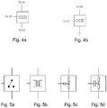
- the communication coupling device CCD is realized by various implementations as depicted in figure 5a,b,c,d .
- the most straightforward implementation is a simple switchover as shown in figure 5a that divides communication signals and measurement signals in the time domain.
- Another implementation is an inductive coupling by means of a transformer, as shown in figure 5b , which separates the communication signals and measurement signals in the time domain, or in the frequency domain, when measurement frequency band and the communication band are set not to overlap.
- Capacitive coupling as shown in figure 5d can also be used to inject communication signals into Ck, which also separates the communication signals and measurement signals in the time domain, or in the frequency domain, when measurement frequency band and the communication band are set not to overlap.
- the communication coupling device can be realized by a direct galvanic connection such as in figure 5c , provided that both the communication system CS and the measurement coupling device CD can withstand each other's signal levels, which also separates the communication signals and measurement signals in the time domain, or in the frequency domain, when measurement frequency band and the communication band are set not to overlap.
- the system realized with a galvanic or inductive coupling is used on one more unused phases of a power cable during the test.
- This coupling comprises a direct, galvanic connection of the communication coupling device CCD to the power cable.
- the communication coupling device CCD can comprise a transformer such that the unused phase is grounded for power frequencies and DC at all times, while the communications signals can still couple in to the cable.
- the communication coupling device CCD is connected to an inductor Lr arranged between the communication system CS and the communication coupling device CCD of the modules M1 and M2 in figure 3a providing a resonant coupling, which constitutes an extension of the capacitive coupling described above, by means of decreasing the losses due to the capacitor Ck.
- the inductor Lr provides a series resonant circuit comprising the capacitor Ck and the inductor Lr. This reduces losses for transmitting and receiving signals normally incurred by the use of a coupling capacitor alone.
- the system as described may also be used for PD measurements on branched power cable circuits by applying it in analogous manner as described above by simply connecting additional measurement modules M2 to the conductor of the power cable at the end of each branch to be tested.
- the PD measurement method may be applied at connection joints along a power cable, in order to increase the measurement sensitivity in detecting partial discharge.
- a current transformer or capacitive coupler is used to measure the partial discharge in combination with a measurement instrument MI.
- connection joints can then also be used for coupling communication signals into and out of the power cable.
Landscapes
- Physics & Mathematics (AREA)
- General Physics & Mathematics (AREA)
- Testing Relating To Insulation (AREA)
- Cable Transmission Systems, Equalization Of Radio And Reduction Of Echo (AREA)
Claims (11)
- Procédé de mesure de décharge partielle sur un câble d'alimentation électrique (PC) comprenant :- la connexion d'un bloc d'alimentation haute tension (PS) à un conducteur haute tension du câble d'alimentation (PC) devant être soumis à un essai à un premier emplacement de deux emplacements de mesure sélectionnés le long du câble d'alimentation (PC), la connexion à chacun des deux emplacements de mesure le long du câble d'alimentation (PC) d'un condensateur (Ck) à un conducteur haute tension (C) du câble d'alimentation (PC), caractérisé par- la connexion à l'extrémité basse tension de chaque condensateur (Ck) d'un dispositif de couplage de communication (CCD) et d'un dispositif de couplage de mesure (CD), où le dispositif de couplage de communication (CCD) et le dispositif de couplage de mesure (CD) sont connectés en série,- la connexion à chaque emplacement de mesure d'un système de communication (CS) au dispositif de couplage de communication (CCD) et la connexion d'un instrument de mesure (MI) au dispositif de couplage de mesure (CD),- la fourniture de signaux haute tension au conducteur porteur de haute tension (C) du câble d'alimentation (PC) au moyen du bloc d'alimentation haute tension (PS),- la réception d'un signal de décharge partielle à chacun des deux emplacements de mesure au moyen des instruments de mesure (MI) et la génération de résultats de mesure de la décharge partielle à chaque emplacement de mesure,- la transmission de résultats de mesure d'une décharge partielle d'un emplacement de mesure via le conducteur haute tension (C) du câble (PC) à l'autre emplacement de mesure,- la réception des résultats de mesure transmis d'une décharge partielle à l'autre emplacement de mesure.
- Procédé selon la revendication 1, caractérisé par- le calcul de l'emplacement de la décharge partielle à l'aide des résultats de mesure depuis les deux emplacements de mesure.
- Procédé selon la revendication 1, caractérisé par
la saisie de paramètres de mesure via une interface utilisateur (UI) connectée au système de communication (CS). - Procédé selon la revendication 1, caractérisé par
la saisie de paramètres de mesure via un dispositif de mesure et de commande automatisé connecté au système de communication (CS). - Utilisation du procédé selon l'une des revendications 1 à 4 pour une mesure de décharge partielle sur un système de câble d'alimentation dérivé, où un condensateur (Ck), un dispositif de couplage de communication (CCD), un système de communication (CS) et des instruments de mesure (MI) sont connectés au conducteur du câble à plus de deux emplacements de mesure.
- Utilisation du procédé selon l'une des revendications 1 à 4 pour soumettre à essai un câble d'alimentation ayant des joints de connexion, où le condensateur (Ck, des dispositifs de couplage de communication (CCD), un système de communication (CS), un dispositif de couplage de mesure (CD) et des instruments de mesure (MI) sont connectés au câble à plusieurs emplacements de joint de connexion.
- Système configuré pour réaliser le procédé selon la revendication 1 pour soumettre à essai un câble d'alimentation électrique (PC) comprenant- un bloc d'alimentation haute tension (PS) pouvant être connecté à un conducteur haute tension (C) du câble d'alimentation (PC),- deux modules d'essai (M1, M2) configurés pour être connectés au conducteur haute tension (C) du câble d'alimentation (PC) en deux points de mesure sélectionnés sur le câble d'alimentation (PC),chaque module d'essai (M1, M2) contenant :- un condensateur haute tension (Ck), pouvant être connecté au conducteur haute tension (C) du câble d'alimentation (PC) en les deux points de mesure sur le câble d'alimentation (PC),
caractérisé par- un dispositif de couplage de communication (CCD) connecté à l'extrémité basse tension du condensateur (Ck) et- un dispositif de couplage de mesure (CD) connecté au dispositif de couplage de communication (CCD) et- un instrument de mesure (MI) connecté au dispositif de couplage de mesure (CD) et- un système de communication (CS) connecté au dispositif de couplage de communication (CCD) et à l'instrument de mesure (MI). - Système configuré pour réaliser le procédé selon la revendication 1 pour soumettre à essai un câble d'alimentation électrique (PC) comprenant- un bloc d'alimentation haute tension (PS) pouvant être connecté à un conducteur haute tension (C) du câble d'alimentation (PC),- deux modules d'essai (Ml', M2') configurés pour être connectés au conducteur haute tension (C) du câble d'alimentation (PC) en deux points de mesure sélectionnés sur le câble d'alimentation (PC),chaque module d'essai (M1', M2') contenant :- un condensateur haute tension (Ck), pouvant être connecté au conducteur haute tension (C) du câble d'alimentation (PC) en les deux points de mesure sur le câble d'alimentation (PC),
caractérisé par- un dispositif de couplage de mesure (CD) connecté à l'extrémité basse tension du condensateur (Ck) et- un dispositif de couplage de communication (CCD) connecté au dispositif de couplage de mesure (CD) et- un instrument de mesure (MI) connecté au dispositif de couplage de mesure (CD) et- un système de communication (CS) connecté au dispositif de couplage de communication (CCD) et à l'instrument de mesure (MI). - Système selon la revendication 7 ou 8, caractérisé en ce que
le dispositif de couplage de communication (CCD) est matérialisé par un couplage galvanique, inductif ou capacitif ou par un commutateur. - Système selon la revendication 7 ou 8, caractérisé en ce que
le dispositif de couplage de communication (CCD) comprend un commutateur, un transformateur, un résistor, ou un condensateur. - Système selon l'une des revendications 7 à 10, caractérisé en ce que
une bobine d'induction (Lr) est agencée entre le dispositif de couplage de communication (CCD) et le système de communication (CS).
Applications Claiming Priority (1)
| Application Number | Priority Date | Filing Date | Title |
|---|---|---|---|
| CH8552015 | 2015-06-15 |
Publications (2)
| Publication Number | Publication Date |
|---|---|
| EP3106888A1 EP3106888A1 (fr) | 2016-12-21 |
| EP3106888B1 true EP3106888B1 (fr) | 2020-08-12 |
Family
ID=56360158
Family Applications (1)
| Application Number | Title | Priority Date | Filing Date |
|---|---|---|---|
| EP16173059.3A Active EP3106888B1 (fr) | 2015-06-15 | 2016-06-06 | Procédé et système de mesure de décharge partielle sur un câble d'alimentation |
Country Status (1)
| Country | Link |
|---|---|
| EP (1) | EP3106888B1 (fr) |
Families Citing this family (3)
| Publication number | Priority date | Publication date | Assignee | Title |
|---|---|---|---|---|
| DE102017116613B3 (de) | 2017-07-24 | 2018-08-09 | Maschinenfabrik Reinhausen Gmbh | Verfahren und Prüfvorrichtung zur Messung von Teilentladungsimpulsen eines geschirmten Kabels |
| AT523525B1 (de) | 2020-03-31 | 2021-09-15 | Baur Gmbh | Elektrische Schaltungsanordnung |
| CN119920218B (zh) * | 2025-04-01 | 2025-06-13 | 杭州明特科技有限公司 | 一种控制按键唤醒屏幕的方法、系统及存储介质 |
Family Cites Families (7)
| Publication number | Priority date | Publication date | Assignee | Title |
|---|---|---|---|---|
| NL1005349C2 (nl) * | 1997-02-24 | 1998-08-26 | Kema Nv | Werkwijze en inrichting voor het opsporen en lokaliseren van onregelmatigheden in een diëlectricum. |
| NL1020925C2 (nl) | 2002-06-21 | 2004-01-20 | Stichting Tech Wetenschapp | Werkwijze en systeem voor het overbrengen van een informatiesignaal over een vermogenskabel. |
| US7705607B2 (en) * | 2006-08-25 | 2010-04-27 | Instrument Manufacturing Company | Diagnostic methods for electrical cables utilizing axial tomography |
| WO2011109674A1 (fr) * | 2010-03-05 | 2011-09-09 | Ambient Corporation | Evaluation des courants de bruit et des surintensités sur une ligne électrique |
| NL2005431C2 (en) | 2010-10-01 | 2012-04-03 | Locamation B V | Method and system for on-line measurement in power cables. |
| ES2660291T3 (es) * | 2013-10-17 | 2018-03-21 | Power Plus Communications Ag | Dispositivo de acoplamiento para acoplar una unidad terminal de línea eléctrica y un dispositivo de medición a una red de energía eléctrica, así como un nodo de medición |
| DE102014220421A1 (de) * | 2013-10-24 | 2015-04-30 | Power Plus Communications Ag | Messknoten, System und Verfahren zur Überwachung des Zustands eines Energieversorgungsnetzwerks |
-
2016
- 2016-06-06 EP EP16173059.3A patent/EP3106888B1/fr active Active
Non-Patent Citations (1)
| Title |
|---|
| None * |
Also Published As
| Publication number | Publication date |
|---|---|
| EP3106888A1 (fr) | 2016-12-21 |
Similar Documents
| Publication | Publication Date | Title |
|---|---|---|
| US9482699B2 (en) | Method and apparatus for monitoring high voltage bushings safely | |
| US5352984A (en) | Fault and splice finding system and method | |
| JP5007649B2 (ja) | 部分放電測定装置、部分放電測定装置の校正方法および部分放電測定方法 | |
| US11280849B2 (en) | Method for measuring an impedance of an electric cable, a coupler arrangement and uses thereof | |
| CN102159956B (zh) | 飞行器布线的电弧故障位点检测 | |
| CA2397973C (fr) | Liaison d'essai de detection de decharge partielle, systeme de detection de decharge partielle, et procedes de detection de decharge partielle sur un cable d'energie | |
| US7915898B1 (en) | Integrated cable/connector shielding surveillance system | |
| US9146268B2 (en) | Method and device for monitoring a sheath voltage arrester of a cable system | |
| EP1038185B1 (fr) | Systeme d'isolation a large bande | |
| KR102811866B1 (ko) | Ic의 노이즈 내량 검출 장치 및 ic의 노이즈 내량 검출 방법 | |
| US12007427B2 (en) | Electrical circuit | |
| EP3106888B1 (fr) | Procédé et système de mesure de décharge partielle sur un câble d'alimentation | |
| EP2725367A1 (fr) | Procédé et dispositif de surveillance des décharges partielles | |
| CN103245395A (zh) | 按照雷达原理工作的料位测量系统 | |
| EP1516194B1 (fr) | Procede et systeme pour transmettre un signal d'information sur un cable electrique | |
| US11668751B2 (en) | Sensor device and method for determining an alternating voltage | |
| US4241305A (en) | Method and apparatus for locating faults in electric cables | |
| RU2703195C1 (ru) | Способ определения расстояния до места отражения в электрическом проводнике | |
| CN108344927B (zh) | 一种电力电缆局部放电监测装置及方法 | |
| JP5344673B2 (ja) | 有線式配電線遠方監視制御用通信ケーブルの障害点またはルートの探査装置 | |
| Clegg et al. | Modern cable-fault-location methods | |
| Lewin et al. | Condition monitoring of power cables | |
| JPH09281175A (ja) | ケーブル探知装置 | |
| Wouters et al. | Application of Open-air Capacitive Sensors for Voltage Monitoring near Terminations in HV and EHV Insulated Connections | |
| JP3348522B2 (ja) | 電力機器用絶縁監視装置 |
Legal Events
| Date | Code | Title | Description |
|---|---|---|---|
| PUAI | Public reference made under article 153(3) epc to a published international application that has entered the european phase |
Free format text: ORIGINAL CODE: 0009012 |
|
| STAA | Information on the status of an ep patent application or granted ep patent |
Free format text: STATUS: THE APPLICATION HAS BEEN PUBLISHED |
|
| AK | Designated contracting states |
Kind code of ref document: A1 Designated state(s): AL AT BE BG CH CY CZ DE DK EE ES FI FR GB GR HR HU IE IS IT LI LT LU LV MC MK MT NL NO PL PT RO RS SE SI SK SM TR |
|
| AX | Request for extension of the european patent |
Extension state: BA ME |
|
| STAA | Information on the status of an ep patent application or granted ep patent |
Free format text: STATUS: REQUEST FOR EXAMINATION WAS MADE |
|
| 17P | Request for examination filed |
Effective date: 20170619 |
|
| RBV | Designated contracting states (corrected) |
Designated state(s): AL AT BE BG CH CY CZ DE DK EE ES FI FR GB GR HR HU IE IS IT LI LT LU LV MC MK MT NL NO PL PT RO RS SE SI SK SM TR |
|
| RIN1 | Information on inventor provided before grant (corrected) |
Inventor name: GULSKI, EDWARD Inventor name: QUAK, BENJAMIN Inventor name: SEITZ, PAUL PETER Inventor name: WILD, MANUEL |
|
| GRAP | Despatch of communication of intention to grant a patent |
Free format text: ORIGINAL CODE: EPIDOSNIGR1 |
|
| STAA | Information on the status of an ep patent application or granted ep patent |
Free format text: STATUS: GRANT OF PATENT IS INTENDED |
|
| INTG | Intention to grant announced |
Effective date: 20200313 |
|
| GRAJ | Information related to disapproval of communication of intention to grant by the applicant or resumption of examination proceedings by the epo deleted |
Free format text: ORIGINAL CODE: EPIDOSDIGR1 |
|
| STAA | Information on the status of an ep patent application or granted ep patent |
Free format text: STATUS: REQUEST FOR EXAMINATION WAS MADE |
|
| GRAP | Despatch of communication of intention to grant a patent |
Free format text: ORIGINAL CODE: EPIDOSNIGR1 |
|
| STAA | Information on the status of an ep patent application or granted ep patent |
Free format text: STATUS: GRANT OF PATENT IS INTENDED |
|
| INTC | Intention to grant announced (deleted) | ||
| INTG | Intention to grant announced |
Effective date: 20200525 |
|
| GRAS | Grant fee paid |
Free format text: ORIGINAL CODE: EPIDOSNIGR3 |
|
| GRAA | (expected) grant |
Free format text: ORIGINAL CODE: 0009210 |
|
| STAA | Information on the status of an ep patent application or granted ep patent |
Free format text: STATUS: THE PATENT HAS BEEN GRANTED |
|
| AK | Designated contracting states |
Kind code of ref document: B1 Designated state(s): AL AT BE BG CH CY CZ DE DK EE ES FI FR GB GR HR HU IE IS IT LI LT LU LV MC MK MT NL NO PL PT RO RS SE SI SK SM TR |
|
| REG | Reference to a national code |
Ref country code: CH Ref legal event code: EP |
|
| REG | Reference to a national code |
Ref country code: IE Ref legal event code: FG4D |
|
| REG | Reference to a national code |
Ref country code: DE Ref legal event code: R096 Ref document number: 602016041737 Country of ref document: DE |
|
| REG | Reference to a national code |
Ref country code: AT Ref legal event code: REF Ref document number: 1302073 Country of ref document: AT Kind code of ref document: T Effective date: 20200915 |
|
| REG | Reference to a national code |
Ref country code: CH Ref legal event code: NV Representative=s name: SPIERENBURG AND PARTNER AG, PATENT- UND MARKEN, CH |
|
| REG | Reference to a national code |
Ref country code: LT Ref legal event code: MG4D |
|
| REG | Reference to a national code |
Ref country code: NL Ref legal event code: MP Effective date: 20200812 |
|
| PG25 | Lapsed in a contracting state [announced via postgrant information from national office to epo] |
Ref country code: HR Free format text: LAPSE BECAUSE OF FAILURE TO SUBMIT A TRANSLATION OF THE DESCRIPTION OR TO PAY THE FEE WITHIN THE PRESCRIBED TIME-LIMIT Effective date: 20200812 Ref country code: SE Free format text: LAPSE BECAUSE OF FAILURE TO SUBMIT A TRANSLATION OF THE DESCRIPTION OR TO PAY THE FEE WITHIN THE PRESCRIBED TIME-LIMIT Effective date: 20200812 Ref country code: GR Free format text: LAPSE BECAUSE OF FAILURE TO SUBMIT A TRANSLATION OF THE DESCRIPTION OR TO PAY THE FEE WITHIN THE PRESCRIBED TIME-LIMIT Effective date: 20201113 Ref country code: FI Free format text: LAPSE BECAUSE OF FAILURE TO SUBMIT A TRANSLATION OF THE DESCRIPTION OR TO PAY THE FEE WITHIN THE PRESCRIBED TIME-LIMIT Effective date: 20200812 Ref country code: NO Free format text: LAPSE BECAUSE OF FAILURE TO SUBMIT A TRANSLATION OF THE DESCRIPTION OR TO PAY THE FEE WITHIN THE PRESCRIBED TIME-LIMIT Effective date: 20201112 Ref country code: BG Free format text: LAPSE BECAUSE OF FAILURE TO SUBMIT A TRANSLATION OF THE DESCRIPTION OR TO PAY THE FEE WITHIN THE PRESCRIBED TIME-LIMIT Effective date: 20201112 Ref country code: LT Free format text: LAPSE BECAUSE OF FAILURE TO SUBMIT A TRANSLATION OF THE DESCRIPTION OR TO PAY THE FEE WITHIN THE PRESCRIBED TIME-LIMIT Effective date: 20200812 |
|
| PG25 | Lapsed in a contracting state [announced via postgrant information from national office to epo] |
Ref country code: PL Free format text: LAPSE BECAUSE OF FAILURE TO SUBMIT A TRANSLATION OF THE DESCRIPTION OR TO PAY THE FEE WITHIN THE PRESCRIBED TIME-LIMIT Effective date: 20200812 Ref country code: NL Free format text: LAPSE BECAUSE OF FAILURE TO SUBMIT A TRANSLATION OF THE DESCRIPTION OR TO PAY THE FEE WITHIN THE PRESCRIBED TIME-LIMIT Effective date: 20200812 Ref country code: LV Free format text: LAPSE BECAUSE OF FAILURE TO SUBMIT A TRANSLATION OF THE DESCRIPTION OR TO PAY THE FEE WITHIN THE PRESCRIBED TIME-LIMIT Effective date: 20200812 Ref country code: RS Free format text: LAPSE BECAUSE OF FAILURE TO SUBMIT A TRANSLATION OF THE DESCRIPTION OR TO PAY THE FEE WITHIN THE PRESCRIBED TIME-LIMIT Effective date: 20200812 Ref country code: IS Free format text: LAPSE BECAUSE OF FAILURE TO SUBMIT A TRANSLATION OF THE DESCRIPTION OR TO PAY THE FEE WITHIN THE PRESCRIBED TIME-LIMIT Effective date: 20201212 |
|
| PG25 | Lapsed in a contracting state [announced via postgrant information from national office to epo] |
Ref country code: CZ Free format text: LAPSE BECAUSE OF FAILURE TO SUBMIT A TRANSLATION OF THE DESCRIPTION OR TO PAY THE FEE WITHIN THE PRESCRIBED TIME-LIMIT Effective date: 20200812 Ref country code: DK Free format text: LAPSE BECAUSE OF FAILURE TO SUBMIT A TRANSLATION OF THE DESCRIPTION OR TO PAY THE FEE WITHIN THE PRESCRIBED TIME-LIMIT Effective date: 20200812 Ref country code: RO Free format text: LAPSE BECAUSE OF FAILURE TO SUBMIT A TRANSLATION OF THE DESCRIPTION OR TO PAY THE FEE WITHIN THE PRESCRIBED TIME-LIMIT Effective date: 20200812 Ref country code: SM Free format text: LAPSE BECAUSE OF FAILURE TO SUBMIT A TRANSLATION OF THE DESCRIPTION OR TO PAY THE FEE WITHIN THE PRESCRIBED TIME-LIMIT Effective date: 20200812 Ref country code: EE Free format text: LAPSE BECAUSE OF FAILURE TO SUBMIT A TRANSLATION OF THE DESCRIPTION OR TO PAY THE FEE WITHIN THE PRESCRIBED TIME-LIMIT Effective date: 20200812 |
|
| REG | Reference to a national code |
Ref country code: DE Ref legal event code: R097 Ref document number: 602016041737 Country of ref document: DE |
|
| REG | Reference to a national code |
Ref country code: AT Ref legal event code: UEP Ref document number: 1302073 Country of ref document: AT Kind code of ref document: T Effective date: 20200812 |
|
| PG25 | Lapsed in a contracting state [announced via postgrant information from national office to epo] |
Ref country code: AL Free format text: LAPSE BECAUSE OF FAILURE TO SUBMIT A TRANSLATION OF THE DESCRIPTION OR TO PAY THE FEE WITHIN THE PRESCRIBED TIME-LIMIT Effective date: 20200812 Ref country code: ES Free format text: LAPSE BECAUSE OF FAILURE TO SUBMIT A TRANSLATION OF THE DESCRIPTION OR TO PAY THE FEE WITHIN THE PRESCRIBED TIME-LIMIT Effective date: 20200812 |
|
| PLBE | No opposition filed within time limit |
Free format text: ORIGINAL CODE: 0009261 |
|
| STAA | Information on the status of an ep patent application or granted ep patent |
Free format text: STATUS: NO OPPOSITION FILED WITHIN TIME LIMIT |
|
| PG25 | Lapsed in a contracting state [announced via postgrant information from national office to epo] |
Ref country code: SK Free format text: LAPSE BECAUSE OF FAILURE TO SUBMIT A TRANSLATION OF THE DESCRIPTION OR TO PAY THE FEE WITHIN THE PRESCRIBED TIME-LIMIT Effective date: 20200812 |
|
| 26N | No opposition filed |
Effective date: 20210514 |
|
| PG25 | Lapsed in a contracting state [announced via postgrant information from national office to epo] |
Ref country code: IT Free format text: LAPSE BECAUSE OF FAILURE TO SUBMIT A TRANSLATION OF THE DESCRIPTION OR TO PAY THE FEE WITHIN THE PRESCRIBED TIME-LIMIT Effective date: 20200812 |
|
| PG25 | Lapsed in a contracting state [announced via postgrant information from national office to epo] |
Ref country code: SI Free format text: LAPSE BECAUSE OF FAILURE TO SUBMIT A TRANSLATION OF THE DESCRIPTION OR TO PAY THE FEE WITHIN THE PRESCRIBED TIME-LIMIT Effective date: 20200812 |
|
| PG25 | Lapsed in a contracting state [announced via postgrant information from national office to epo] |
Ref country code: MC Free format text: LAPSE BECAUSE OF FAILURE TO SUBMIT A TRANSLATION OF THE DESCRIPTION OR TO PAY THE FEE WITHIN THE PRESCRIBED TIME-LIMIT Effective date: 20200812 |
|
| REG | Reference to a national code |
Ref country code: BE Ref legal event code: MM Effective date: 20210630 |
|
| PG25 | Lapsed in a contracting state [announced via postgrant information from national office to epo] |
Ref country code: LU Free format text: LAPSE BECAUSE OF NON-PAYMENT OF DUE FEES Effective date: 20210606 |
|
| PG25 | Lapsed in a contracting state [announced via postgrant information from national office to epo] |
Ref country code: IE Free format text: LAPSE BECAUSE OF NON-PAYMENT OF DUE FEES Effective date: 20210606 |
|
| PG25 | Lapsed in a contracting state [announced via postgrant information from national office to epo] |
Ref country code: FR Free format text: LAPSE BECAUSE OF NON-PAYMENT OF DUE FEES Effective date: 20210630 |
|
| PG25 | Lapsed in a contracting state [announced via postgrant information from national office to epo] |
Ref country code: BE Free format text: LAPSE BECAUSE OF NON-PAYMENT OF DUE FEES Effective date: 20210630 |
|
| PG25 | Lapsed in a contracting state [announced via postgrant information from national office to epo] |
Ref country code: PT Free format text: LAPSE BECAUSE OF FAILURE TO SUBMIT A TRANSLATION OF THE DESCRIPTION OR TO PAY THE FEE WITHIN THE PRESCRIBED TIME-LIMIT Effective date: 20201214 |
|
| PG25 | Lapsed in a contracting state [announced via postgrant information from national office to epo] |
Ref country code: HU Free format text: LAPSE BECAUSE OF FAILURE TO SUBMIT A TRANSLATION OF THE DESCRIPTION OR TO PAY THE FEE WITHIN THE PRESCRIBED TIME-LIMIT; INVALID AB INITIO Effective date: 20160606 |
|
| PG25 | Lapsed in a contracting state [announced via postgrant information from national office to epo] |
Ref country code: CY Free format text: LAPSE BECAUSE OF FAILURE TO SUBMIT A TRANSLATION OF THE DESCRIPTION OR TO PAY THE FEE WITHIN THE PRESCRIBED TIME-LIMIT Effective date: 20200812 |
|
| PGFP | Annual fee paid to national office [announced via postgrant information from national office to epo] |
Ref country code: GB Payment date: 20230622 Year of fee payment: 8 |
|
| PG25 | Lapsed in a contracting state [announced via postgrant information from national office to epo] |
Ref country code: MK Free format text: LAPSE BECAUSE OF FAILURE TO SUBMIT A TRANSLATION OF THE DESCRIPTION OR TO PAY THE FEE WITHIN THE PRESCRIBED TIME-LIMIT Effective date: 20200812 |
|
| PG25 | Lapsed in a contracting state [announced via postgrant information from national office to epo] |
Ref country code: MT Free format text: LAPSE BECAUSE OF FAILURE TO SUBMIT A TRANSLATION OF THE DESCRIPTION OR TO PAY THE FEE WITHIN THE PRESCRIBED TIME-LIMIT Effective date: 20200812 |
|
| GBPC | Gb: european patent ceased through non-payment of renewal fee |
Effective date: 20240606 |
|
| PG25 | Lapsed in a contracting state [announced via postgrant information from national office to epo] |
Ref country code: GB Free format text: LAPSE BECAUSE OF NON-PAYMENT OF DUE FEES Effective date: 20240606 |
|
| PGFP | Annual fee paid to national office [announced via postgrant information from national office to epo] |
Ref country code: DE Payment date: 20250618 Year of fee payment: 10 |
|
| PGFP | Annual fee paid to national office [announced via postgrant information from national office to epo] |
Ref country code: AT Payment date: 20250616 Year of fee payment: 10 |
|
| PGFP | Annual fee paid to national office [announced via postgrant information from national office to epo] |
Ref country code: CH Payment date: 20250701 Year of fee payment: 10 |
|
| PG25 | Lapsed in a contracting state [announced via postgrant information from national office to epo] |
Ref country code: TR Free format text: LAPSE BECAUSE OF FAILURE TO SUBMIT A TRANSLATION OF THE DESCRIPTION OR TO PAY THE FEE WITHIN THE PRESCRIBED TIME-LIMIT Effective date: 20200812 |