EP3106939A2 - Utilisation d'un système de pesée agricole mobile permettant de surveiller et de stocker des données opérationnelles auxiliaires à des fins de diagnostic sur équipement remorqué et sur tracteur - Google Patents
Utilisation d'un système de pesée agricole mobile permettant de surveiller et de stocker des données opérationnelles auxiliaires à des fins de diagnostic sur équipement remorqué et sur tracteur Download PDFInfo
- Publication number
- EP3106939A2 EP3106939A2 EP16170692.4A EP16170692A EP3106939A2 EP 3106939 A2 EP3106939 A2 EP 3106939A2 EP 16170692 A EP16170692 A EP 16170692A EP 3106939 A2 EP3106939 A2 EP 3106939A2
- Authority
- EP
- European Patent Office
- Prior art keywords
- machine
- operational parameters
- control indicator
- machine control
- date
- Prior art date
- Legal status (The legal status is an assumption and is not a legal conclusion. Google has not performed a legal analysis and makes no representation as to the accuracy of the status listed.)
- Ceased
Links
Images



Classifications
-
- A—HUMAN NECESSITIES
- A01—AGRICULTURE; FORESTRY; ANIMAL HUSBANDRY; HUNTING; TRAPPING; FISHING
- A01B—SOIL WORKING IN AGRICULTURE OR FORESTRY; PARTS, DETAILS, OR ACCESSORIES OF AGRICULTURAL MACHINES OR IMPLEMENTS, IN GENERAL
- A01B76/00—Parts, details or accessories of agricultural machines or implements, not provided for in groups A01B51/00 - A01B75/00
-
- A—HUMAN NECESSITIES
- A01—AGRICULTURE; FORESTRY; ANIMAL HUSBANDRY; HUNTING; TRAPPING; FISHING
- A01C—PLANTING; SOWING; FERTILISING
- A01C7/00—Sowing
- A01C7/20—Parts of seeders for conducting and depositing seed
-
- A—HUMAN NECESSITIES
- A01—AGRICULTURE; FORESTRY; ANIMAL HUSBANDRY; HUNTING; TRAPPING; FISHING
- A01K—ANIMAL HUSBANDRY; AVICULTURE; APICULTURE; PISCICULTURE; FISHING; REARING OR BREEDING ANIMALS, NOT OTHERWISE PROVIDED FOR; NEW BREEDS OF ANIMALS
- A01K5/00—Feeding devices for stock or game ; Feeding wagons; Feeding stacks
-
- A—HUMAN NECESSITIES
- A01—AGRICULTURE; FORESTRY; ANIMAL HUSBANDRY; HUNTING; TRAPPING; FISHING
- A01K—ANIMAL HUSBANDRY; AVICULTURE; APICULTURE; PISCICULTURE; FISHING; REARING OR BREEDING ANIMALS, NOT OTHERWISE PROVIDED FOR; NEW BREEDS OF ANIMALS
- A01K5/00—Feeding devices for stock or game ; Feeding wagons; Feeding stacks
- A01K5/001—Fodder distributors with mixer or shredder
-
- B—PERFORMING OPERATIONS; TRANSPORTING
- B01—PHYSICAL OR CHEMICAL PROCESSES OR APPARATUS IN GENERAL
- B01F—MIXING, e.g. DISSOLVING, EMULSIFYING OR DISPERSING
- B01F33/00—Other mixers; Mixing plants; Combinations of mixers
- B01F33/50—Movable or transportable mixing devices or plants
- B01F33/502—Vehicle-mounted mixing devices
- B01F33/5023—Vehicle-mounted mixing devices the vehicle being a trailer which is hand moved or coupled to self-propelling vehicles
-
- B—PERFORMING OPERATIONS; TRANSPORTING
- B01—PHYSICAL OR CHEMICAL PROCESSES OR APPARATUS IN GENERAL
- B01F—MIXING, e.g. DISSOLVING, EMULSIFYING OR DISPERSING
- B01F35/00—Accessories for mixers; Auxiliary operations or auxiliary devices; Parts or details of general application
- B01F35/20—Measuring; Control or regulation
- B01F35/21—Measuring
- B01F35/211—Measuring of the operational parameters
-
- B—PERFORMING OPERATIONS; TRANSPORTING
- B01—PHYSICAL OR CHEMICAL PROCESSES OR APPARATUS IN GENERAL
- B01F—MIXING, e.g. DISSOLVING, EMULSIFYING OR DISPERSING
- B01F35/00—Accessories for mixers; Auxiliary operations or auxiliary devices; Parts or details of general application
- B01F35/20—Measuring; Control or regulation
- B01F35/21—Measuring
- B01F35/212—Measuring of the driving system data, e.g. torque, speed or power data
-
- B—PERFORMING OPERATIONS; TRANSPORTING
- B01—PHYSICAL OR CHEMICAL PROCESSES OR APPARATUS IN GENERAL
- B01F—MIXING, e.g. DISSOLVING, EMULSIFYING OR DISPERSING
- B01F35/00—Accessories for mixers; Auxiliary operations or auxiliary devices; Parts or details of general application
- B01F35/20—Measuring; Control or regulation
- B01F35/22—Control or regulation
- B01F35/2201—Control or regulation characterised by the type of control technique used
- B01F35/2206—Use of stored recipes for controlling the computer programs, e.g. for manipulation, handling, production or composition in mixing plants
-
- B—PERFORMING OPERATIONS; TRANSPORTING
- B01—PHYSICAL OR CHEMICAL PROCESSES OR APPARATUS IN GENERAL
- B01F—MIXING, e.g. DISSOLVING, EMULSIFYING OR DISPERSING
- B01F35/00—Accessories for mixers; Auxiliary operations or auxiliary devices; Parts or details of general application
- B01F35/20—Measuring; Control or regulation
- B01F35/22—Control or regulation
- B01F35/2201—Control or regulation characterised by the type of control technique used
- B01F35/2207—Use of data, i.e. barcodes, 3D codes or similar type of tagging information, as instruction or identification codes for controlling the computer programs, e.g. for manipulation, handling, production or compounding in mixing plants
-
- G—PHYSICS
- G05—CONTROLLING; REGULATING
- G05B—CONTROL OR REGULATING SYSTEMS IN GENERAL; FUNCTIONAL ELEMENTS OF SUCH SYSTEMS; MONITORING OR TESTING ARRANGEMENTS FOR SUCH SYSTEMS OR ELEMENTS
- G05B23/00—Testing or monitoring of control systems or parts thereof
- G05B23/02—Electric testing or monitoring
- G05B23/0205—Electric testing or monitoring by means of a monitoring system capable of detecting and responding to faults
- G05B23/0259—Electric testing or monitoring by means of a monitoring system capable of detecting and responding to faults characterized by the response to fault detection
- G05B23/0264—Control of logging system, e.g. decision on which data to store; time-stamping measurements
-
- G—PHYSICS
- G07—CHECKING-DEVICES
- G07C—TIME OR ATTENDANCE REGISTERS; REGISTERING OR INDICATING THE WORKING OF MACHINES; GENERATING RANDOM NUMBERS; VOTING OR LOTTERY APPARATUS; ARRANGEMENTS, SYSTEMS OR APPARATUS FOR CHECKING NOT PROVIDED FOR ELSEWHERE
- G07C5/00—Registering or indicating the working of vehicles
- G07C5/008—Registering or indicating the working of vehicles communicating information to a remotely located station
-
- G—PHYSICS
- G08—SIGNALLING
- G08B—SIGNALLING SYSTEMS, e.g. PERSONAL CALLING SYSTEMS; ORDER TELEGRAPHS; ALARM SYSTEMS
- G08B21/00—Alarms responsive to a single specified undesired or abnormal condition and not otherwise provided for
- G08B21/18—Status alarms
- G08B21/182—Level alarms, e.g. alarms responsive to variables exceeding a threshold
-
- B—PERFORMING OPERATIONS; TRANSPORTING
- B01—PHYSICAL OR CHEMICAL PROCESSES OR APPARATUS IN GENERAL
- B01F—MIXING, e.g. DISSOLVING, EMULSIFYING OR DISPERSING
- B01F2101/00—Mixing characterised by the nature of the mixed materials or by the application field
- B01F2101/06—Mixing of food ingredients
- B01F2101/09—Mixing of cereals, grains or seeds materials
-
- B—PERFORMING OPERATIONS; TRANSPORTING
- B01—PHYSICAL OR CHEMICAL PROCESSES OR APPARATUS IN GENERAL
- B01F—MIXING, e.g. DISSOLVING, EMULSIFYING OR DISPERSING
- B01F27/00—Mixers with rotary stirring devices in fixed receptacles; Kneaders
-
- B—PERFORMING OPERATIONS; TRANSPORTING
- B01—PHYSICAL OR CHEMICAL PROCESSES OR APPARATUS IN GENERAL
- B01F—MIXING, e.g. DISSOLVING, EMULSIFYING OR DISPERSING
- B01F35/00—Accessories for mixers; Auxiliary operations or auxiliary devices; Parts or details of general application
- B01F35/10—Maintenance of mixers
-
- B—PERFORMING OPERATIONS; TRANSPORTING
- B01—PHYSICAL OR CHEMICAL PROCESSES OR APPARATUS IN GENERAL
- B01F—MIXING, e.g. DISSOLVING, EMULSIFYING OR DISPERSING
- B01F35/00—Accessories for mixers; Auxiliary operations or auxiliary devices; Parts or details of general application
- B01F35/20—Measuring; Control or regulation
- B01F35/21—Measuring
- B01F35/211—Measuring of the operational parameters
- B01F35/2117—Weight
-
- B—PERFORMING OPERATIONS; TRANSPORTING
- B01—PHYSICAL OR CHEMICAL PROCESSES OR APPARATUS IN GENERAL
- B01F—MIXING, e.g. DISSOLVING, EMULSIFYING OR DISPERSING
- B01F35/00—Accessories for mixers; Auxiliary operations or auxiliary devices; Parts or details of general application
- B01F35/20—Measuring; Control or regulation
- B01F35/22—Control or regulation
- B01F35/2201—Control or regulation characterised by the type of control technique used
- B01F35/2209—Controlling the mixing process as a whole, i.e. involving a complete monitoring and controlling of the mixing process during the whole mixing cycle
-
- B—PERFORMING OPERATIONS; TRANSPORTING
- B01—PHYSICAL OR CHEMICAL PROCESSES OR APPARATUS IN GENERAL
- B01F—MIXING, e.g. DISSOLVING, EMULSIFYING OR DISPERSING
- B01F35/00—Accessories for mixers; Auxiliary operations or auxiliary devices; Parts or details of general application
- B01F35/20—Measuring; Control or regulation
- B01F35/22—Control or regulation
- B01F35/221—Control or regulation of operational parameters, e.g. level of material in the mixer, temperature or pressure
- B01F35/2214—Speed during the operation
- B01F35/22142—Speed of the mixing device during the operation
-
- B—PERFORMING OPERATIONS; TRANSPORTING
- B01—PHYSICAL OR CHEMICAL PROCESSES OR APPARATUS IN GENERAL
- B01F—MIXING, e.g. DISSOLVING, EMULSIFYING OR DISPERSING
- B01F35/00—Accessories for mixers; Auxiliary operations or auxiliary devices; Parts or details of general application
- B01F35/20—Measuring; Control or regulation
- B01F35/22—Control or regulation
- B01F35/221—Control or regulation of operational parameters, e.g. level of material in the mixer, temperature or pressure
- B01F35/2216—Time, i.e. duration, of at least one parameter during the operation
- B01F35/22161—Time, i.e. duration, of at least one parameter during the operation duration of the mixing process or parts of it
-
- G—PHYSICS
- G05—CONTROLLING; REGULATING
- G05B—CONTROL OR REGULATING SYSTEMS IN GENERAL; FUNCTIONAL ELEMENTS OF SUCH SYSTEMS; MONITORING OR TESTING ARRANGEMENTS FOR SUCH SYSTEMS OR ELEMENTS
- G05B2219/00—Program-control systems
- G05B2219/20—Pc systems
- G05B2219/24—Pc safety
- G05B2219/24015—Monitoring
-
- G—PHYSICS
- G05—CONTROLLING; REGULATING
- G05B—CONTROL OR REGULATING SYSTEMS IN GENERAL; FUNCTIONAL ELEMENTS OF SUCH SYSTEMS; MONITORING OR TESTING ARRANGEMENTS FOR SUCH SYSTEMS OR ELEMENTS
- G05B2219/00—Program-control systems
- G05B2219/20—Pc systems
- G05B2219/24—Pc safety
- G05B2219/24055—Trace, store a working, operation history
-
- G—PHYSICS
- G05—CONTROLLING; REGULATING
- G05B—CONTROL OR REGULATING SYSTEMS IN GENERAL; FUNCTIONAL ELEMENTS OF SUCH SYSTEMS; MONITORING OR TESTING ARRANGEMENTS FOR SUCH SYSTEMS OR ELEMENTS
- G05B2219/00—Program-control systems
- G05B2219/20—Pc systems
- G05B2219/24—Pc safety
- G05B2219/24067—Processor stores variables, events and date in eeprom, for external monitor
-
- G—PHYSICS
- G05—CONTROLLING; REGULATING
- G05B—CONTROL OR REGULATING SYSTEMS IN GENERAL; FUNCTIONAL ELEMENTS OF SUCH SYSTEMS; MONITORING OR TESTING ARRANGEMENTS FOR SUCH SYSTEMS OR ELEMENTS
- G05B2219/00—Program-control systems
- G05B2219/20—Pc systems
- G05B2219/24—Pc safety
- G05B2219/24084—Remote and local monitoring, local result to remote, remote takes action
-
- G—PHYSICS
- G05—CONTROLLING; REGULATING
- G05B—CONTROL OR REGULATING SYSTEMS IN GENERAL; FUNCTIONAL ELEMENTS OF SUCH SYSTEMS; MONITORING OR TESTING ARRANGEMENTS FOR SUCH SYSTEMS OR ELEMENTS
- G05B2219/00—Program-control systems
- G05B2219/20—Pc systems
- G05B2219/26—Pc applications
- G05B2219/2663—Tractor
-
- G—PHYSICS
- G05—CONTROLLING; REGULATING
- G05B—CONTROL OR REGULATING SYSTEMS IN GENERAL; FUNCTIONAL ELEMENTS OF SUCH SYSTEMS; MONITORING OR TESTING ARRANGEMENTS FOR SUCH SYSTEMS OR ELEMENTS
- G05B2219/00—Program-control systems
- G05B2219/30—Nc systems
- G05B2219/31—From computer integrated manufacturing till monitoring
- G05B2219/31462—Add time stamp to alarm message
Definitions
- Agricultural machines may include various controls and sensors in order to control operation of the various aspects of the machines.
- An agricultural machine indicator also referred to as an "indicator" provides an interface through which a user can perform operations such as modifying control parameters, options and/or settings and accessing machine information such as operating conditions.
- the large numbers of settings and options indicators offer provide benefits and challenges to users (also referred to as end users).
- On the positive side indicators can be customized to meet a wide variety of needs.
- OEM Original Equipment Manufacturer
- OEM OEM
- indicator manufacturer also referred to as the "indicator provider”
- the functionality described herein provides OEMs, especially Mixer OEMs, with the ability to more closely monitor their equipment by providing access to an Hours of Use and a Maintenance Message functionality.
- Capabilities for software updates add an additional element to the need for remote access.
- a system and method provides a means to connect via radio or directly with the indicator that provides a means to access and setup the indicator as well as a means to update the software on the indicator.
- a method and system for monitoring trailed and truck-mounted agricultural equipment uses a machine control indicator.
- the method and system provides the ability to transfer machine operation data to diagnose any problems and help the operator use the machine to obtain the best machine performance possible.
- a machine control indicator system (also referred to as a scale indicator system) provides monitoring and recording capability for operational data on: system settings, weight, rotation, revolutions per minute, peak weights, gearbox temperatures, hydraulic pressures, and the minimum and maximum limits of this data, on mobile agricultural Seed Tenders, Planters, Seed Drills, Air Seeders, Grain Carts, or Feed Mixers.
- This system utilizes wired, wireless, or data transfer devices such as USB Drives for the transfer of this data.
- the system allows for the transfer of data required to diagnose drive and weighing system operation from the machine's location to another location via email or wireless communication (such as Wi-Fi), thus allowing for real-time user viewable data related to the operation of the machinery.
- the method and system described herein employs the concept of utilizing the electronics of the scale system to provide additional monitoring and data collection of machine operational parameters related to: weight, rotation (On/Off), revolutions per minute, peak weights, temperatures of gearboxes, and temperatures and pressures of hydraulic systems, and the minimum and maximum limits for each of these parameters, with the date and time at which each event is recorded.
- the Operator or Service Technician can download the recorded data using a USB Memory Device, Wired Cable Connection via Serial or CANBUS Communication, or wireless communication, to a computer or smart device equipped with a program or application that will display both the raw data in tabular form and with a graphical means based on a timeline.
- the graphical display of the data allows the viewer to easily determine when an event, or events, results in a concurrent effect on another component or the machine operating system as a whole.
- a method of operation of a machine control indicator located on a first machine includes the step of monitoring operational parameters of a second machine operationally associated with a first machine.
- Each of the operational parameters is associated with a common clock of the machine control indicator.
- the operational parameters are stored in a memory of the machine control indicator with a date and time stamp based on the common clock.
- the operational parameters are transmitted along with the date and time stamp to a user device separate from the first machine and the second machine.
- the operational parameters comprise one or more of a weight value, a rotation value, a revolutions per minute value, a peak weight value, a gearbox temperature value, and a hydraulic pressure value.
- the operational parameters in one embodiment, are received from sensors located on the second machine.
- the data from the user device pertaining to operation of one of the first machine and the second machine is received. Actuators associated with one of the first machine and the second machine are controlled based on the data from the user device.
- the monitoring comprises receiving data from sensors located on one of the first machine and the second machine.
- the second machine trails the first machine in one embodiment and can be one of a seed tender, a planter, a seed drill, an air seeder, a grain cart, and a feed mixer.
- the operational parameters are transmitted to a customer service device via the user device.
- a method of operation of a machine control indicator includes the step of monitoring operational parameters of an agricultural machine.
- Each of the operational parameters is associated with a common clock of the machine control indicator.
- the operational parameters are stored in a memory of the machine control indicator with a date and time stamp based on the common clock.
- the operational parameters are transmitted along with the date and time stamp to a user device separate from the agricultural machine.
- an Animal Feed Mixer (Dairy or Beef) Scale indicator system records Feed Mixer Operating Speed along with the operating temperatures and hydraulic & lube oil pressures of the mixer gearboxes and hydraulic drive system and notifies the operator and records the temperature or pressures, along with the weight, date, and time, when limits have been exceeded.
- the system records when the temperature and/or pressures of the mixer gearbox(s) and hydrostatic drive system monitored by the scale indicator system exceed limits along with the weight of material in the mixer, and the operating speed of the main mixer auger, rotor, or reel (as noted above), with the time and date.
- the system can also display a warning message that the temperature or pressure limit has been exceeded.
- Agricultural Feed Mixers whether mounted on a trailer frame or truck chassis do not usually have an electronic system that will display warnings regarding the operating temperatures and pressures of the system being out of norm (like the oil pressure and temperature warning lights on an automobile). Therefore a need exists to display warnings in order to help protect the expensive components of the feed mixer's drive system.
- the system described herein consists of a machine control indicator that also includes sensor inputs for rotational speed, pressure, and temperature.
- the indicator is programmed with the required temperature and pressure limits (high, low, or both) that a particular machine is designed to operate within. These programming settings are secured by a "factory" access code that is not available to the end user.
- the indicator can display a "High Oil Temperature”, “Low Oil Pressure”, or “High Oil Pressure” warning on the display of the indicator in lieu of the weight information that is normally displayed. To clear the warning the operator will need to press a specific key to acknowledge.
- the indicator can, at the same time as the above, record the following background information in an even record regarding the warning: Date, Time, Revolutions per Minute, Weight in Mixer, and the Temperature or Pressure.
- the event records are retained, in one embodiment, in non-volatile memory which cannot be deleted without a factory access code and a special key sequence.
- the event records can be downloaded though the indicator's USB port.
- the system can record the Rotations per Minute of the primary mixing auger(s), rotor, or reel of an agricultural Feed Mixer along with the weight of feed in the mixer with date & time.
- the "Time" spent mixing is dependent on the speed that the mixer is turning.
- the mix process is dependent on the number of turns of the mixer, not the time. For example; by careful observation the farmer finds that it takes 4 minutes at 20 rpm to achieve the correct mix. This equals 100 turns of the mixer. If the farmer's father operates the mixer at 3 ⁇ 4 speed (15 rpm) he will need to run the mixer for an additional minute (5 minutes total) to achieve the same 100 turns of the mixer.
- the system consists of:
- the output data from the system can be displayed in a spreadsheet or graph showing Weight and RPM over Time.
- the concept of recording the Revolutions Per Minute while mixing, and the Total Revolutions that take place to make a mix, of the Feed Mixer is beneficial to the indicator provider, machine provider, and machine user.
- This information indicator provider can provide both the end user, and the manufacturer of the mixer, with data and information that is useful and important.
- the farm owner/manager can determine if the employees operating the mixer are following instructions and are operating the mixer at the correct speed for each step and for the correct amount of time.
- the system also senses the operating temperatures and hydraulic & lube oil pressures of the mixer gearboxes and hydraulic drive system and notifies the operator and records the temperature or pressures, along with the weight, date, and time, when limits have been exceeded.
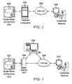
- FIG. 1 depicts a system for remote indicator access according to one embodiment.
- a tractor 100 has a machine attached.
- the machine is a feed mixer 102 for mixing ingredients to be fed to animals.
- Feed mixer 102 is shown in the process of receiving ingredients from front loader 104.
- Tractor 100 has a machine control indicator 106 (also referred to as a scale display or scale indicator) which can be located in the cab of tractor 100 to provide information to a user.
- Machine control indicator 106 can be mounted in other locations as well such as on feed mixer 102.
- Machine control indicator 106 receives inputs from various sensors including rotations per minute (RPM) sensor 108, pressure sensor 110, and temperature sensor 112.
- RPM rotations per minute
- Machine control indicator 106 is also in communication with load cell junction box 114 which receives data from load cells 116 and 118 (also referred to as weight sensors) which can be used to provide weight information to indicator 106.
- load cells 116 and 118 also referred to as weight sensors
- sensors 108, 110, and 112, and load cell junction box 114 are wired to machine control indicator 106.
- various data can be transmitted from sensors wirelessly to machine control indicator 106.
- the data that machine control indicator 106 receives can be referred to as operational parameters or operational performance data.
- machine control indicator 106 is also connected to various outputs such as alarms (e.g., 12 volt wired audible alarm).
- Machine control indicator 106 is in communication with a user device 120 which can be any electronic device capable of communicating with machine control head 106.
- user device 120 can be a smart phone or tablet.
- user device 120 receives information from machine control indicator 106 which can then be displayed via an application (also referred to as app) or program executed by user device 120.
- User device 120 is also in communication with other devices via network 122 which can be any type of network such as a wide area network or local area network.
- user device 120 communicates with a customer service device 124 and other devices via a network 122, such as the Internet.
- information displayed by machine control indicator 106 can also be viewed by user device 120.
- User device 120 can also be used to remotely interact with machine control indicator 106 in a manner similar to a user interacting directly with machine control indicator 106.
- a user can also allow another user, such as a customer service representative to view information displayed by machine control indicator 106.
- user device 120 can act as a conduit to allow a user, such as a customer service representative, to interact with machine control indicator 106 using customer service device 124.
- Customer service device in one embodiment, is a desktop computer but can be any type of device capable of communicating with user device 120 and indicator 106.
- machine control indicator 106 is capable of communicating simultaneously with user device 120 and customer service device 124. Various communications can be facilitated by machine control indicator 106.
- Figure 2 depicts one embodiment in which machine control indicator 202 is in communication with customer service device 208 via a user device 204 and wide area network 206 (in this case, the internet).
- a customer service representative can use customer service device 208 running a remote access program to connect through wide area network 206 and user device 204 to allow data to be transferred from machine control indicator 202 to customer service device 208 and back.
- the transfer of information can be used to provide capabilities including remote cab control, menu setup setting transfer, other record transfer, etc.
- Figure 3 depicts one embodiment in which machine control indicator 302 communicates with a customer service device 310 via a customer's local network.
- machine control indicator 302 is in communication with customer's desktop computer 306 via the customer's wireless device 304 (e.g., a Wi-Fi router).
- Customer's desktop computer 306 is in communication with customer service device 310 via network 308 (e.g., the internet).
- network 308 e.g., the internet
- a customer service person can use customer service device 208 running a remote access program to connect to machine control indicator 302 through wide area network 308, customer's desktop computer 306, and customer's wireless device 304 to allow data to be transferred from machine control indicator 302 to customer service device 310 and back.
- the transfer of information can be used to provide capabilities including remote cab control, menu setup setting transfer, other record transfer, etc.
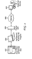
- Figure 4 depicts one embodiment in which machine control indicator 402 communicates with customer service device 410 via customer's computer 404 (e.g., a laptop), customer's wireless device 406 and wide area network 408 (e.g., the internet).
- Customer's computer 404 communicates with machine control indicator 402 and transmits information received from machine control indicator 402 to customer service device 410.
- Customer's computer 404 also transmits information from customer service device 410 to machine control indicator 402.
- the transfer of information can be used to provide capabilities including remote cab control, menu setup setting transfer, other record transfer, etc.
- the wireless capability of the machine control indicator allows a user with a user device to stand in the general vicinity of the indicator and communicate with the indicator. This wireless capability allows a user to move around a machine associated with the machine control indicator and still view information from the indicator as well as control the indicator. As such, a user can perform various tasks without the need to be within reach of the indicator.
- a customer service device can receive information directly from an indicator or via a user device.
- Various configurations which allow a customer service representative to view and/or modify indicator settings and information or a user to view and/or modify indicator settings are possible using one of the embodiments shown in Figures 1 through 4 .
- a machine control indicator (e.g., 106, 202, 302, or 402) is provided with wireless circuitry internally mounted.
- wireless circuitry is added to a machine control indicator in the form of an external add on device.
- Such an external device in one embodiment is connected to the machine control indicator via a wired connection, such as a wired connection to a serial port.
- a J905 connector, or other connector is added to machine control indictor to allow the machine control indicator to be connected to other devices using, for example, an external radio module (ERM) or serial cable.
- ERM external radio module
- an internal diagnostic cable is located inside a machine control indicator that allows connection to other devices using, for example, an ERM or serial cable.
- an internal diagnostic connection point e.g., a header
- each machine control indicator that allows connection to other devices using, for example, an ERM or serial cable.
- communication among machine control indicator 106, user device 120, and customer service device 124 facilitates multiple operations as follows.
- Communication facilitates bi-directional transfer of indicator calibration and menu settings to and through the application (referred to as an "app") operating on user device 120.
- an application referred to as an "app" operating on user device 120.
- This allows service centers to connect to the indicator to backup and/or change the indicator's menu settings remotely.
- the indicator's menu settings can be transferred to and stored on the app to create a backup on the app device, to e-mail the settings to a customer service center for review, to transfer revised settings e-mailed from a customer service center through the app to the indicator, and/or allow data located on the app to be accessible to e-mail and other apps.
- information provided by an indicator can be viewed remotely using various devices.
- "cab control" allows a user to view indicator information and interact with an indicator remotely.
- a device facilitating cab control can be located in a cab of front loader 104 shown in Figure 1 .
- Cab control allows a user in the cab of front loader 104 to see how much of an ingredient has been added to mixer 102 as the user is operating front loader 104 and may not be in viewing range of an indicator associated with mixer 102.
- Communication also facilitates real-time cab control via customer service device 124.
- customer service device 124 This provides a customer service representative with the ability to interact with the indicator remotely in a manner similar to how a user can interact directly with the indicator. This allows a remote customer service representative to see everything a local cab control app screen is displaying on a user device. It also allows the service center to operate the indicator remotely (e.g., push keys, read the display, change menu settings, etc.). It also allows the service center to observe how a customer is running the indicator.
- Communication also facilitates cab control via user device 120. This allows user device 120 to interact with the indicator remotely (e.g., push buttons, read the display, change calibration and menu settings, etc.) via an app running on user device 120. It should be noted that real-time cab control via customer service device 124 and via user device 120 can occur simultaneously.
- a rotation counter and/or timer provides a user with a timer countdown display and alarm activation functionality to allow the operator to take the user device with them and leave the mixing area to perform other tasks until the mix finishes.
- Communication also facilitates an hour meter.
- An hour meter value can be displayed on the app.
- An hour meter value can be transferred to the app to allow additional maintenance messages to be displayed in accordance with OEM recommendations.
- maintenance messages can be edited on the app. Editing can include editing of the message text to be displayed on the app and the number of hours at which the message is to be activated.
- messages are displayed via a pop-up box with the message and a button such as "OK" or "Clear" which requires a response from a user.
- Hour meter value information can be transferred to and/or from a service center.
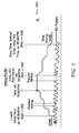
- FIG. 5 depicts graph 500 of a mixing profile according to one embodiment.
- Graph 500 depicts an RPM profile of how a user has been running their machine which can aid in determining if the user is mixing correctly.
- mixing profile data is captured as follows.
- Section A depicts data captured for each mixer load. Data is collected for the entire feed cycle including loading the mixer with ingredients, mixing the ingredients (mix time) and unloading of the mixer. In one embodiment, data is captured for at least the last 50 loads.
- Starting point 502 is when the gross weight meets or exceeds the "Mix Log Start Point Weight” menu setting (default 300 lbs.) and pulses are being detected for the Rotation Counter (meaning the mix auger is rotating).
- the data logged for each mixer load at the "Start Pont" includes:
- Mid-Point 504 is when the gross weight decreases by the new "Mix Log Mid-Point Weight Tolerance" Menu setting (default 300 lbs.) This is to determine when the user has finished the loading / mixing process and is starting to unload the mixer. For example, a user adds and mixes feed ingredients up to mid-point 504. At mid-point 504, a discharge door or gate of the mixer is opened so that the feed can be discharged from the feed mixer for access by animals, such as livestock. A user may need to move the feed mixer around an area in order to discharge feed at various locations. As shown in Figure 5 , after mid-point 504, the weight of feed measured decreases as the feed mixer is emptied. The speed of the feed mixer is detected and recorded during the time the feed mixer is discharged.
- the method also supports shutting the mix auger OFF, pausing, and back ON again during the loading process. If the Rotation Counter stops seeing pulses (i.e. they have turned OFF the mix auger), the "Total Mix Time” is paused and then continues to accumulate the “Total Mix Time” when Rotation Counter pulses begin again.
- the mix auger must be rotating to unload a feed mixer, so rotation counter pulses should be seen while unloading the 300lbs.
- the data logged for mid-point 504 includes:
- Stop Point 506 is when the gross weight decreases into the Zero/Balance point + the new "Mix Log Start Point Weight" described previously.
- the method also supports shutting the mix auger OFF, pausing and back ON again during the unloading process. If the Rotation Counter stops seeing pulses (i.e. they have turned OFF the mix auger), the "Total Mix Time” is paused and then continues to accumulate the “Total Mix Time” when Rotation Counter pulses begin again. The mix auger must be rotating to unload a feed mixer, so rotation counter pulses should be seen while unloading the 300lbs.
- the data logged for each mixer load at the "Stop Point" includes:
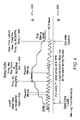
- Figure 6 depicts mixing profile 500 from Figure 5 and also includes mixing log 600.
- data is captured every X number of seconds (e.g., 1-999, with a default of 15). This interval can be identified by a user via a menu setting. The timer interval is selected to provide enough detail to create a chart showing how a feed mixer was used. In one embodiment, such data is captured for each mixer load. The data can be collected for the entire feeding cycle including loading the mixer with ingredients, mixing the ingredients (mix time), and unloading the mixer. Data is stored when a user pauses the mixing cycle (i.e., no rotation pulses). In one embodiment, data is recorded for at least the last 50 loads.
- Rotation pulse data (i.e., RPM) is saved beginning at starting point 502.
- the data logged for each mixer load at start point 502 includes:
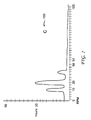
- Figure 7 depicts Hours/RPM graph 700 which shows hours a machine has been run at various RPMs.
- Mixers and other equipment typically have optimal speeds. Recording speed information allows an OEM to know how an end user is using a piece of equipment, such as a mixer. In addition, recorded speed information allows an OEM to determine if changes are required to better use the equipment (i.e., mix ingredients better). Because applications may vary, a flexible way to capture RPM is provided.
- Some examples of possible menu settings include:
- another method for capturing RPM includes:
- All of the data described above can be captured by a machine control head and various sensors.
- the data can be transferred to a customer service center for remote viewing and analysis.
- communication between machine control indicator 106, user device 120 and customer service device 124 also facilitates display of current machine RPM. This allows a user and a customer service representative to see how the user is currently operating a machine, such as a feed mixer.
- Peak weight transfer information is only available to a customer service representative and not a user.
- Communication also facilitates transmission of data pertaining to user input to a machine control indicator.
- key presses reflecting a user interacting with a machine control indicator are recorded and can be transmitted to a customer service representative for viewing and analysis. This information can help a customer service representative understand how a user is interacting with the machine control indicator.
- Communication also facilitates transmission of current alarm status information on a cab control app.
- the current alarm status allows a user to know when to shut off a machine, such as an auger, when away from the scale while loading ingredients from bins, tanks, and/or silos.
- Total mixed rations are recipes used to produce proper feed mixes.
- TMR information is tracked by a machine control indicator and can be retrieved and displayed by a user device and/or a customer service device.
- a customer service representative can use TMR information received from a machine control indicator to determine how a TMR recipe should be adjusted based on information from a user after examination and analysis of feed output from a mixer.
- a customer service representative can also transmit a new and/or modified recipe to a machine control indicator in order to correct an issue with a feed mix.
- the new and/or modified recipe could be created using a feed management computer program (such as TMR Tracker).
- machine control indicator 106 of Figure 1 has additional sensor inputs (e.g., analog and/or digital inputs).
- additional sensors can be used to provide data to machine control indicator 106 in order to record parameters, such as temperature, and produce alarm outputs to alert a user to certain conditions.
- temperature sensors can be placed in machine gearboxes in order to track the temperature of gear fluid in the gearbox and provide warnings to a user as necessary.
- warning messages and/or alarms are provided to a user when a temperature exceeds a value for a temperature parameter set via a menu setting.
- the machine control indicator has a menu setting which allows a user to customize an alpha-numeric message, such as a warning message, to be displayed when a certain condition occurs, such as a maximum temperature being exceeded.
- a maximum temperature being exceeded can produce a warning message, such as "HITEMP", on a display of the machine control indicator.
- a warning message interrupts a displayed weight and the message flashes for 3 seconds.
- a scaled sensor value is flashed for 3 seconds before the indicator returns to displaying a weight.
- the displaying of warning messages and scaled sensor values can be repeated, in one embodiment, every minute, until the input goes below the maximum setting.
- a menu selection of the machine control indicator allows a user to indicate that an alarm light is to be activated when a maximum setting has been reached. For example, a user can set an alarm light to illuminate when a maximum temperature has been met and/or exceeded.
- a menu selection of the machine control indicator allows a user to indicate when an alarm (such as an audible alarm) is to be output. For example, a user can set an alarm to be output when a maximum temperature has been met and/or exceeded.
- the machine control indicator includes a menu setting which allows a user to calibrate and/or scale sensor inputs. In one embodiment, a selection offered by the machine control indicator allows a sensor value to be displayed on a large display such as a six character LCD.
- Machine control indicator 106 can store sensor values. For example, the last 5 peak scaled sensor reading can be stored.
- values to be stored per sensor input include: a scaled sensor value (i.e., gear box 1 temperature - 1234), time (14:10:05), Date (05FE08), and elapsed time over the "maximum setting" value (HHH:MM:SS). This data can be transferred to a customer service device and/or to a web-server for storage and later viewing. Scaled sensor reading, such as temperatures) can be included in both Section A- mixing details (shown in Figure 5 ) and Section B-Mixing log (shown in Figure 6 ).
- the data to be logged for each mixer load at start point 502 includes:
- a data stream including the data above, according to one embodiment, is as follows:
- data storage ends for the mix log at stop point 506 shown in Figures 5 and 6 .
- Figure 8 depicts a flow chart of a method 800 of operation of a machine control indicator 106.
- the method utilizes a mobile agricultural weighing system to monitor and store ancillary operational data for diagnostic purposes on trailed and truck mounted equipment.
- operational parameters of a second machine e.g. feed mixer 102 of Figure 1
- a first machine e.g. tractor 100
- the monitoring is performed by the machine control indicator 106 (shown in Figure 1 ) located on a first machine (such as tractor 100 shown in Figure 1 ).
- each of the operational parameters are associated with a common clock of the machine control indicator.
- the common clock allows various parameters to be tracked using the common clock so that they can be compared with to one another based on time of occurrence.
- the operational parameters are stored in a memory of the machine control indicator with a date and time stamp based on the common clock.
- the operational parameters are transmitted, along with the date and time stamp, to a user device (e.g., user device 120) separate from the first machine and the second machine.
- the operational parameters comprise one or more of a weight value, a rotation value, a revolutions per minute value, a peak weight value, a gearbox temperature value, and a hydraulic pressure value.
- the operational parameters in one embodiment, are received from sensors located on the second machine. For example, a feed mixer trailed behind a tractor can be fitted with various sensor that send data to the machine control indicator located in tractor.
- data is received from the user device pertaining to operation of one of the first machine or the second machine.
- the data can pertain to operation of tractor 100 or feed mixer 102 shown in Figure 1 .
- actuators associated with one of the first machine and the second machine are actuated based on data received from the user device.
- one or more operations such as engine speed, steering, and/or drive speed (e.g., operations controlled from within the cab of tractor 100) can be controlled using data received from the user device.
- the monitoring comprises receiving data from sensors located on one of the first machine and the second machine.
- the second machine in one embodiment, trails the first machine and can comprise one of a seed tender, a planter, a seed drill, an air seeder, a grain cart, and a feed mixer.
- the operational parameters are transmitted to a customer service device from the user device.
- Machine control indicator 106 of Figure 1 machine control indicators shown in other figures, and other components can be implemented using a computer.
- a high-level block diagram of such a computer is illustrated in Figure 9 .
- Computer 902 contains a processor 904 which controls the overall operation of the computer 902 by executing computer program instructions which define such operation.
- the computer program instructions may be stored in a storage device 912, or other computer readable medium (e.g., magnetic disk, CD ROM, etc.), and loaded into memory 910 when execution of the computer program instructions is desired.
- the method steps of Figure 8 can be defined by the computer program instructions stored in the memory 910 and/or storage 912 and controlled by the processor 904 executing the computer program instructions.
- the computer program instructions can be implemented as computer executable code programmed by one skilled in the art to perform an algorithm defined by the method steps of Figure 8 . Accordingly, by executing the computer program instructions, the processor 904 executes an algorithm defined by the method steps of Figure 8 .
- the computer 902 also includes one or more network interfaces 906 for communicating with other devices via a network.
- the computer 902 also includes input/output devices 908 that enable user interaction with the computer 902 (e.g., display, keyboard, mouse, speakers, buttons, etc.)
- Figure 9 is a high level representation of some of the components of such a computer for illustrative purposes.
Landscapes
- Life Sciences & Earth Sciences (AREA)
- Environmental Sciences (AREA)
- Engineering & Computer Science (AREA)
- Chemical & Material Sciences (AREA)
- Chemical Kinetics & Catalysis (AREA)
- Physics & Mathematics (AREA)
- General Physics & Mathematics (AREA)
- Soil Sciences (AREA)
- Biodiversity & Conservation Biology (AREA)
- Birds (AREA)
- Animal Husbandry (AREA)
- Automation & Control Theory (AREA)
- Mechanical Engineering (AREA)
- General Engineering & Computer Science (AREA)
- Software Systems (AREA)
- Business, Economics & Management (AREA)
- Emergency Management (AREA)
- Apparatuses For Bulk Treatment Of Fruits And Vegetables And Apparatuses For Preparing Feeds (AREA)
- Management, Administration, Business Operations System, And Electronic Commerce (AREA)
- Arrangements For Transmission Of Measured Signals (AREA)
- Control Of Transmission Device (AREA)
- Accessories For Mixers (AREA)
- Catching Or Destruction (AREA)
- Testing And Monitoring For Control Systems (AREA)
- Mixers Of The Rotary Stirring Type (AREA)
Applications Claiming Priority (1)
| Application Number | Priority Date | Filing Date | Title |
|---|---|---|---|
| US201562165547P | 2015-05-22 | 2015-05-22 |
Publications (2)
| Publication Number | Publication Date |
|---|---|
| EP3106939A2 true EP3106939A2 (fr) | 2016-12-21 |
| EP3106939A3 EP3106939A3 (fr) | 2017-03-15 |
Family
ID=56684425
Family Applications (3)
| Application Number | Title | Priority Date | Filing Date |
|---|---|---|---|
| EP16170710.4A Ceased EP3106940A3 (fr) | 2015-05-22 | 2016-05-20 | Surveillance et enregistrement de diagnostic de composants de système hydraulique sur des mélangeurs agricoles |
| EP16170692.4A Ceased EP3106939A3 (fr) | 2015-05-22 | 2016-05-20 | Utilisation d'un système de pesée agricole mobile permettant de surveiller et de stocker des données opérationnelles auxiliaires à des fins de diagnostic sur équipement remorqué et sur tracteur |
| EP16170716.1A Ceased EP3106941A3 (fr) | 2015-05-22 | 2016-05-20 | Enregistrement de la vitesse de rotation d'un mélangeur avec le poids du fourrage, date et heure |
Family Applications Before (1)
| Application Number | Title | Priority Date | Filing Date |
|---|---|---|---|
| EP16170710.4A Ceased EP3106940A3 (fr) | 2015-05-22 | 2016-05-20 | Surveillance et enregistrement de diagnostic de composants de système hydraulique sur des mélangeurs agricoles |
Family Applications After (1)
| Application Number | Title | Priority Date | Filing Date |
|---|---|---|---|
| EP16170716.1A Ceased EP3106941A3 (fr) | 2015-05-22 | 2016-05-20 | Enregistrement de la vitesse de rotation d'un mélangeur avec le poids du fourrage, date et heure |
Country Status (2)
| Country | Link |
|---|---|
| US (5) | US10786794B2 (fr) |
| EP (3) | EP3106940A3 (fr) |
Cited By (2)
| Publication number | Priority date | Publication date | Assignee | Title |
|---|---|---|---|---|
| CN112708787A (zh) * | 2021-03-26 | 2021-04-27 | 北京亿晟科技有限公司 | 一种基于镧铈稀土加工生产的混合搅拌系统 |
| EP4338588A1 (fr) * | 2022-09-13 | 2024-03-20 | Mayer Verwaltungs GmbH & Co. KG | Procédé de commande d'une transmission et chariot mélangeur de fourrage |
Families Citing this family (15)
| Publication number | Priority date | Publication date | Assignee | Title |
|---|---|---|---|---|
| DE102014103857A1 (de) * | 2014-03-20 | 2015-09-24 | Gea Farm Technologies Gmbh | Schwenkbarer Futtermischer |
| US10786794B2 (en) * | 2015-05-22 | 2020-09-29 | Digi-Star, Llc | Recording mixer rotation rate along with weight of feed and date and time |
| US9751058B2 (en) * | 2015-09-04 | 2017-09-05 | Patz Corporation | Agricultural feed mixer transmission torque sensor assembly |
| JP6889389B2 (ja) * | 2016-09-15 | 2021-06-18 | コベルコ建機株式会社 | 稼働管理システム及び稼働情報の開示方法 |
| US9818287B1 (en) * | 2016-11-09 | 2017-11-14 | Altec Industries, Inc. | Load-indicative alarm |
| UA126066C2 (uk) * | 2016-12-01 | 2022-08-10 | Кінз Меньюфекчурінг, Інк. | Системи, способи і/або пристрої для забезпечення користувацького дисплея та інтерфейсу для використання з сільськогосподарським знаряддям |
| US11185833B2 (en) * | 2018-05-31 | 2021-11-30 | Kuhn North America, Inc. | Control system for a livestock feed mixer |
| WO2020051060A1 (fr) * | 2018-09-06 | 2020-03-12 | Oshkosh Corporation | Détection d'accumulation de béton |
| CA3116429A1 (fr) | 2018-10-24 | 2020-04-30 | Bitstrata Systems Inc. | Suivi de mouvement de materiau et d'etat operationnel de machine |
| US11369056B2 (en) * | 2019-02-01 | 2022-06-28 | Cnh Industrial Canada, Ltd. | Agitation control system |
| US11665995B2 (en) * | 2019-02-01 | 2023-06-06 | Cnh Industrial Canada, Ltd. | Agitation control system |
| US10677637B1 (en) | 2019-04-04 | 2020-06-09 | Scale Tec, Ltd. | Scale controller with dynamic weight measurement |
| US11650093B2 (en) | 2021-01-19 | 2023-05-16 | Scale-Tec Ltd. | Material weight measurement system with automatic tare associated with object presence detection |
| AU2022242863A1 (en) * | 2021-03-24 | 2023-07-27 | Precision Planting Llc | Systems and methods for determining state data for agricultural parameters and providing spatial state maps |
| WO2023235941A1 (fr) * | 2022-06-06 | 2023-12-14 | De Oliveira Matheus Santetti | Système et procédé de pesage appliqués à des engins agricoles et similaires |
Citations (6)
| Publication number | Priority date | Publication date | Assignee | Title |
|---|---|---|---|---|
| US20050246439A1 (en) * | 1999-11-16 | 2005-11-03 | Avery Fong | Method and system of remote diagnostic, control and information collection using a dynamic linked library |
| US20130346917A1 (en) * | 2012-06-22 | 2013-12-26 | Microsoft Corporation | Client application analytics |
| US20140273827A1 (en) * | 2013-03-15 | 2014-09-18 | David Killpack | System and method for processing and displaying agricultural data |
| US20150054655A1 (en) * | 2013-08-21 | 2015-02-26 | Navico Holding As | Usage Data for Marine Electronics Device |
| GB2517792A (en) * | 2013-09-03 | 2015-03-04 | Jaguar Land Rover Ltd | Human-machine interface |
| WO2015045910A1 (fr) * | 2013-09-30 | 2015-04-02 | 株式会社クボタ | Dispositif de collecte de données, engin de travail comprenant un dispositif de collecte de données, et système utilisant un dispositif de collecte de données |
Family Cites Families (48)
| Publication number | Priority date | Publication date | Assignee | Title |
|---|---|---|---|---|
| US2912351A (en) * | 1956-09-21 | 1959-11-10 | Sylvania Electric Prod | Lens coating apparatus and process |
| US4907799A (en) * | 1989-01-23 | 1990-03-13 | Danner Michael R | Extensible-retractable pool and billiard cue bridgestick |
| DE4426245A1 (de) * | 1994-07-23 | 1996-02-22 | Gruenenthal Gmbh | 1-Phenyl-3-dimethylamino-propanverbindungen mit pharmakologischer Wirkung |
| JPH1019645A (ja) | 1996-07-05 | 1998-01-23 | Yazaki Corp | 積載重量表示装置 |
| US6024035A (en) | 1997-09-23 | 2000-02-15 | Case Corporation | Seed planting rate maintenance control with rate display |
| US6079340A (en) | 1997-09-23 | 2000-06-27 | Case Corporation | Apparatus for customizing the rate at which farming material is applied to an agricultural field |
| WO2000052627A1 (fr) | 1999-03-01 | 2000-09-08 | North Carolina State University | Systeme et procede de surveillance de grue et de recuperation de donnees |
| DE19940084B4 (de) * | 1999-08-24 | 2012-01-19 | Welger Maschinenfabrik Gmbh | Futtermischwagen |
| US6572257B2 (en) * | 2001-01-31 | 2003-06-03 | Digi-Star, Llc | Combination mixer counter and weight calculator unit for agricultural mixer and method therefor |
| US9565275B2 (en) | 2012-02-09 | 2017-02-07 | Rockwell Automation Technologies, Inc. | Transformation of industrial data into useful cloud information |
| US7211745B1 (en) | 2003-07-22 | 2007-05-01 | The Regents Of The University Of California | Precision harvesting and analysis techniques for crops |
| US7493482B2 (en) | 2005-12-21 | 2009-02-17 | Caterpillar Inc. | Self-configurable information management system |
| US20070233349A1 (en) * | 2006-03-29 | 2007-10-04 | Segal Michael L | Method and apparatus for dynamic control of engine settings in a delivery vehicle |
| WO2008021137A2 (fr) | 2006-08-08 | 2008-02-21 | Siemens Energy & Automation, Inc. | Dispositifs, systèmes et procédés concernant une défaillance d'un système de contrôleur plc |
| US7454304B2 (en) | 2006-09-29 | 2008-11-18 | Digi-Star, Llc | Peak weight detector and method |
| ITBO20070461A1 (it) | 2007-07-04 | 2009-01-05 | Dinamica Generale S R L | Sistema per controllare il caricamento di uno o piu' alimenti in una unita' semovente di miscelazione tramite una pala meccanica montata su un veicolo a motore |
| NZ571763A (en) * | 2007-11-30 | 2009-10-30 | Transp Certification Australia | System for monitoring vehicle use |
| US7725294B2 (en) | 2007-12-04 | 2010-05-25 | Clark Equipment Company | Power machine diagnostic system and method |
| US8960995B2 (en) | 2008-03-06 | 2015-02-24 | Salford Engineering Limited | Mixer/feeder apparatus and a device for monitoring operation of the mixer/feeder apparatus |
| KR101405618B1 (ko) * | 2008-03-07 | 2014-06-10 | 엘지전자 주식회사 | 공기 조화 시스템 |
| JP5443507B2 (ja) | 2008-12-03 | 2014-03-19 | サルフォード・エンジニアリング・リミテッド | 1セットの材料から動物飼料を調製する際に使用する混合レジームを決定するための方法および装置、ならびに動物飼料を生産するためのシステム |
| US20120099948A1 (en) | 2010-10-21 | 2012-04-26 | Digi-Star, LLC, a Wisconsin Limited Liability Company | Automatic start / stop controls for agricultural load and transfer equipment |
| GB0916235D0 (en) | 2009-09-16 | 2009-10-28 | Agco Gmbh | Display terminal |
| US8232892B2 (en) | 2009-11-30 | 2012-07-31 | Tiger General, Llc | Method and system for operating a well service rig |
| IT1399442B1 (it) * | 2010-04-16 | 2013-04-19 | Dinamica Generale S R L | Metodo per controllare il caricamento di alimenti in una unita' di miscelazione di alimenti e corrispondente apparecchiatura di controllo |
| US8676620B2 (en) | 2010-05-28 | 2014-03-18 | Agjunction Llc | System and method for workorder management |
| US8608368B2 (en) * | 2010-06-28 | 2013-12-17 | Dinamica Generale S.P.A. | Method and system for controlling loading of food products in a food mixing unit |
| US8365679B2 (en) | 2010-08-20 | 2013-02-05 | Deere & Company | Seed spacing monitoring system for use in an agricultural seeder |
| US9700015B2 (en) | 2010-08-24 | 2017-07-11 | Feedlogic Corporation | System for metering feed in feed lines |
| US8600565B2 (en) * | 2010-11-18 | 2013-12-03 | Kuhn North America, Inc. | Independent auger operation |
| US9182765B2 (en) | 2011-03-02 | 2015-11-10 | Dinamica Generale S.P.A. | System and method for automatically adjusting the dosage of feed products in a livestock feed recipe |
| US8893630B2 (en) | 2011-09-29 | 2014-11-25 | Cnh Industrial Canada, Ltd. | System for controlling air flow within an agricultural product metering system |
| JP5902930B2 (ja) | 2011-12-02 | 2016-04-13 | ヤンマー株式会社 | 遠隔監視システムの管理サーバ |
| US10775271B2 (en) | 2012-08-22 | 2020-09-15 | Ge Global Sourcing Llc | System for determining conicity of a wheel based on measured vibrations |
| US20140097952A1 (en) * | 2012-10-10 | 2014-04-10 | General Electric Company | Systems and methods for comprehensive alarm management |
| US9664249B2 (en) * | 2013-01-11 | 2017-05-30 | Cnh Industrial Canada, Ltd. | System and method of tractor control based on agricultural implement performance |
| US9187259B2 (en) | 2013-03-15 | 2015-11-17 | Unverferth Manufacturing Company, Inc. | Method for controlling an unload operation on a mobile farm implement |
| US9361650B2 (en) * | 2013-10-18 | 2016-06-07 | State Farm Mutual Automobile Insurance Company | Synchronization of vehicle sensor information |
| JP6302645B2 (ja) | 2013-11-12 | 2018-03-28 | 日立建機株式会社 | 作業機械の稼働データ収集装置 |
| US9528594B2 (en) | 2014-09-04 | 2016-12-27 | Baldor Electric Company | Lubrication system for a gear box and associated methods |
| US9683652B2 (en) | 2015-04-22 | 2017-06-20 | Bell Helicopter Textron Inc. | Method for the delivery of lubricant to a rotorcraft gearbox |
| US10786794B2 (en) | 2015-05-22 | 2020-09-29 | Digi-Star, Llc | Recording mixer rotation rate along with weight of feed and date and time |
| US10559138B2 (en) | 2015-12-18 | 2020-02-11 | Ge Global Sourcing Llc | Sensor signal processing system and method |
| US10520351B2 (en) * | 2016-10-11 | 2019-12-31 | Digi-Star, Llc | Method and apparatus for peak weight detection |
| US10499680B2 (en) * | 2017-03-13 | 2019-12-10 | Kuhn North America, Inc. | Control system for a livestock feed mixer |
| US11003167B2 (en) * | 2018-03-23 | 2021-05-11 | Topcon Positioning Systems, Inc. | Method and apparatus for distribution device refill planning |
| US11185833B2 (en) * | 2018-05-31 | 2021-11-30 | Kuhn North America, Inc. | Control system for a livestock feed mixer |
| DE202019106424U1 (de) * | 2019-11-19 | 2021-02-22 | Trioliet B.V. | Futtermischwagen |
-
2016
- 2016-05-19 US US15/158,799 patent/US10786794B2/en active Active
- 2016-05-19 US US15/158,778 patent/US10421050B2/en active Active
- 2016-05-19 US US15/158,825 patent/US11027248B2/en active Active
- 2016-05-20 EP EP16170710.4A patent/EP3106940A3/fr not_active Ceased
- 2016-05-20 EP EP16170692.4A patent/EP3106939A3/fr not_active Ceased
- 2016-05-20 EP EP16170716.1A patent/EP3106941A3/fr not_active Ceased
-
2020
- 2020-07-29 US US16/942,617 patent/US11980860B2/en active Active
-
2024
- 2024-04-11 US US18/632,341 patent/US20240278202A1/en active Pending
Patent Citations (7)
| Publication number | Priority date | Publication date | Assignee | Title |
|---|---|---|---|---|
| US20050246439A1 (en) * | 1999-11-16 | 2005-11-03 | Avery Fong | Method and system of remote diagnostic, control and information collection using a dynamic linked library |
| US20130346917A1 (en) * | 2012-06-22 | 2013-12-26 | Microsoft Corporation | Client application analytics |
| US20140273827A1 (en) * | 2013-03-15 | 2014-09-18 | David Killpack | System and method for processing and displaying agricultural data |
| US20150054655A1 (en) * | 2013-08-21 | 2015-02-26 | Navico Holding As | Usage Data for Marine Electronics Device |
| GB2517792A (en) * | 2013-09-03 | 2015-03-04 | Jaguar Land Rover Ltd | Human-machine interface |
| WO2015045910A1 (fr) * | 2013-09-30 | 2015-04-02 | 株式会社クボタ | Dispositif de collecte de données, engin de travail comprenant un dispositif de collecte de données, et système utilisant un dispositif de collecte de données |
| EP3054409A1 (fr) * | 2013-09-30 | 2016-08-10 | Kubota Corporation | Dispositif de collecte de données, engin de travail comprenant un dispositif de collecte de données, et système utilisant un dispositif de collecte de données |
Cited By (3)
| Publication number | Priority date | Publication date | Assignee | Title |
|---|---|---|---|---|
| CN112708787A (zh) * | 2021-03-26 | 2021-04-27 | 北京亿晟科技有限公司 | 一种基于镧铈稀土加工生产的混合搅拌系统 |
| CN112708787B (zh) * | 2021-03-26 | 2021-06-18 | 北京亿晟科技有限公司 | 一种基于镧铈稀土加工生产的混合搅拌系统 |
| EP4338588A1 (fr) * | 2022-09-13 | 2024-03-20 | Mayer Verwaltungs GmbH & Co. KG | Procédé de commande d'une transmission et chariot mélangeur de fourrage |
Also Published As
| Publication number | Publication date |
|---|---|
| US20240278202A1 (en) | 2024-08-22 |
| US10786794B2 (en) | 2020-09-29 |
| US20160343231A1 (en) | 2016-11-24 |
| US20160339406A1 (en) | 2016-11-24 |
| EP3106939A3 (fr) | 2017-03-15 |
| EP3106940A3 (fr) | 2017-03-15 |
| EP3106941A3 (fr) | 2017-03-15 |
| US11027248B2 (en) | 2021-06-08 |
| US10421050B2 (en) | 2019-09-24 |
| US11980860B2 (en) | 2024-05-14 |
| US20200353430A1 (en) | 2020-11-12 |
| EP3106941A2 (fr) | 2016-12-21 |
| EP3106940A2 (fr) | 2016-12-21 |
| US20160339405A1 (en) | 2016-11-24 |
Similar Documents
| Publication | Publication Date | Title |
|---|---|---|
| US20240278202A1 (en) | Recording feed mixer rotation rate along with weight of feed and date and time | |
| EP1686217B1 (fr) | Dispositif de commande d'information sur le fonctionnement pour une machine de construction et système de commande d'information sur le fonctionnement d'une machine de construction equipée du dispositif | |
| US10028441B2 (en) | Method for controlling an unload operation on a mobile farm implement | |
| EP3054409B1 (fr) | Dispositif de collecte de données | |
| US20220030756A1 (en) | Retrofitting kit to be mounted on an agricultural implement | |
| EP4042848A1 (fr) | Réseau de capteurs d'identification de fréquence radio (rfid) pour machine de travail | |
| US20130197742A1 (en) | Customizable Initiation of Data Recordings | |
| JP2011517933A (ja) | ミキサー/フィーダー装置およびミキサー/フィーダー装置の動作を監視するためのデバイス | |
| US20260048370A1 (en) | Methods and systems for pharmaceutical compounding | |
| KR20150042364A (ko) | 먹이 급이 장치가 구비된 해상 가두리 관리 시스템 | |
| US11503120B2 (en) | Agricultural monitoring system and method | |
| US20120109520A1 (en) | Method for processing agricultural data | |
| US6572257B2 (en) | Combination mixer counter and weight calculator unit for agricultural mixer and method therefor | |
| EP4029358B1 (fr) | Réseau de capteurs d'identification de fréquence radio (rfid) pour machine de travail | |
| US20090018675A1 (en) | Process Control System and Method for Operating a Process Control System | |
| WO2015005802A1 (fr) | Dispositif de gestion de bétail amélioré | |
| JP6148159B2 (ja) | 作業機のデータ収集装置及び作業機のデータ収集装置への条件書き込みシステム | |
| JP2020056569A (ja) | 穀物乾燥機の遠隔管理システム | |
| WO2019102496A1 (fr) | Procédés et systèmes de surveillance et de commande d'équipement(s) agricole(s) fixé(s) à un véhicule agricole | |
| DE10225098A1 (de) | Verfahren zur Erstellung eines Schnitthöhen-Protokolls im laufenden Arbeitsprozess von Erntemaschinen | |
| DE102024124930A1 (de) | Gateway eines landwirtschaftlichen Arbeitsgerätes | |
| CN115187194A (zh) | 青贮作物的收获管理系统 | |
| DE102012107540A1 (de) | Verfahren zur Überwachung eines Milchviehbetriebes mit einer Herde von milchgebenden Tieren | |
| KR20190032246A (ko) | 사료 또는 물 공급 누적량 확인방법 | |
| AU2006216117A1 (en) | Process control system and method for operating a process control system |
Legal Events
| Date | Code | Title | Description |
|---|---|---|---|
| PUAI | Public reference made under article 153(3) epc to a published international application that has entered the european phase |
Free format text: ORIGINAL CODE: 0009012 |
|
| STAA | Information on the status of an ep patent application or granted ep patent |
Free format text: STATUS: THE APPLICATION HAS BEEN PUBLISHED |
|
| AK | Designated contracting states |
Kind code of ref document: A2 Designated state(s): AL AT BE BG CH CY CZ DE DK EE ES FI FR GB GR HR HU IE IS IT LI LT LU LV MC MK MT NL NO PL PT RO RS SE SI SK SM TR |
|
| AX | Request for extension of the european patent |
Extension state: BA ME |
|
| PUAL | Search report despatched |
Free format text: ORIGINAL CODE: 0009013 |
|
| AK | Designated contracting states |
Kind code of ref document: A3 Designated state(s): AL AT BE BG CH CY CZ DE DK EE ES FI FR GB GR HR HU IE IS IT LI LT LU LV MC MK MT NL NO PL PT RO RS SE SI SK SM TR |
|
| AX | Request for extension of the european patent |
Extension state: BA ME |
|
| RIC1 | Information provided on ipc code assigned before grant |
Ipc: G07C 5/00 20060101ALI20170209BHEP Ipc: B01F 15/00 20060101ALI20170209BHEP Ipc: G05B 23/02 20060101AFI20170209BHEP Ipc: B01F 13/00 20060101ALI20170209BHEP Ipc: A01K 5/00 20060101ALI20170209BHEP |
|
| STAA | Information on the status of an ep patent application or granted ep patent |
Free format text: STATUS: REQUEST FOR EXAMINATION WAS MADE |
|
| 17P | Request for examination filed |
Effective date: 20170915 |
|
| RBV | Designated contracting states (corrected) |
Designated state(s): AL AT BE BG CH CY CZ DE DK EE ES FI FR GB GR HR HU IE IS IT LI LT LU LV MC MK MT NL NO PL PT RO RS SE SI SK SM TR |
|
| STAA | Information on the status of an ep patent application or granted ep patent |
Free format text: STATUS: EXAMINATION IS IN PROGRESS |
|
| 17Q | First examination report despatched |
Effective date: 20190611 |
|
| STAA | Information on the status of an ep patent application or granted ep patent |
Free format text: STATUS: THE APPLICATION HAS BEEN REFUSED |
|
| 18R | Application refused |
Effective date: 20220517 |