EP3106990A1 - Procédé, logiciel et unité de traitement permettant de vérifier les propriétés de composants interactifs - Google Patents
Procédé, logiciel et unité de traitement permettant de vérifier les propriétés de composants interactifs Download PDFInfo
- Publication number
- EP3106990A1 EP3106990A1 EP15305950.6A EP15305950A EP3106990A1 EP 3106990 A1 EP3106990 A1 EP 3106990A1 EP 15305950 A EP15305950 A EP 15305950A EP 3106990 A1 EP3106990 A1 EP 3106990A1
- Authority
- EP
- European Patent Office
- Prior art keywords
- component
- child
- graph
- components
- interactive
- Prior art date
- Legal status (The legal status is an assumption and is not a legal conclusion. Google has not performed a legal analysis and makes no representation as to the accuracy of the status listed.)
- Withdrawn
Links
Images


Classifications
-
- G—PHYSICS
- G06—COMPUTING OR CALCULATING; COUNTING
- G06F—ELECTRIC DIGITAL DATA PROCESSING
- G06F8/00—Arrangements for software engineering
- G06F8/30—Creation or generation of source code
-
- G—PHYSICS
- G06—COMPUTING OR CALCULATING; COUNTING
- G06F—ELECTRIC DIGITAL DATA PROCESSING
- G06F11/00—Error detection; Error correction; Monitoring
- G06F11/36—Prevention of errors by analysis, debugging or testing of software
- G06F11/3604—Analysis of software for verifying properties of programs
- G06F11/3608—Analysis of software for verifying properties of programs using formal methods, e.g. model checking, abstract interpretation
-
- G—PHYSICS
- G06—COMPUTING OR CALCULATING; COUNTING
- G06F—ELECTRIC DIGITAL DATA PROCESSING
- G06F8/00—Arrangements for software engineering
- G06F8/30—Creation or generation of source code
- G06F8/34—Graphical or visual programming
-
- G—PHYSICS
- G06—COMPUTING OR CALCULATING; COUNTING
- G06F—ELECTRIC DIGITAL DATA PROCESSING
- G06F8/00—Arrangements for software engineering
- G06F8/30—Creation or generation of source code
- G06F8/38—Creation or generation of source code for implementing user interfaces
Definitions
- the present invention relates to the verification of properties on interactive software. More specifically, it relates to the formulation and verification of properties on interactive components organized as hierarchical structures of interactive components within interactive software.
- Verification and validation are important processes in engineering. Validation consists in using available methods for checking that a system is fit for its purpose. Verifying a system consists in defining properties that said system must have at all times, and using available methods for checking that said properties are indeed guaranteed in the system.
- the verification of software requires specific methods.
- Software components are collections of instructions that can be developed independently and assembled to produce software products.
- a software property is a trait or an attribute proper to a software component.
- the verification of software can be performed as a process that consists in checking whether a given property or set of properties is true or false on a given software product or software component.
- a component property is true if it is fulfilled by the software component or false if it is not fulfilled.
- Test consists in submitting the system (a software product or a software component) to a controlled environment, observing its behavior and comparing it to a reference, for example a specification.
- Test is a simple method, easy to use and very trustable, but it can be very costly if the controlled environment is complex to build; this is particularly true when testing the interactions of software with users or the environment.
- Reviewing consists in submitting the system to one or several reviewers for examination, comment or approval. Reviewing is simple and flexible, but its cost increases dramatically with the desired reliability level, and its efficiency decreases with the complexity of software because finding errors or checking properties is difficult when the structure of software is difficult to read.
- Analysis consists of building a model of the system, verifying and validating this model. Then if a model holds a property and if the system is built according to said model, said final system holds said property.
- Various modeling techniques and model analysis methods exist. For example, state-transition models can be built and the graph resulting from an exhaustive simulation can be used to support verification of temporal related properties like LTL or CTL as described in Baier et al. Principles of model-checking, MIT Press,k ISBN 026202649X, 9780262026499 .
- Another approach consists in performing mathematical proof on a model by applying inference rules with the objective to check that a property is preserved when adding more detail to the model as described by Abrial, The B-Book - Assigning Programs to Meanings, 2005 .
- an abstract semantic can be extracted from the source code of programs, and used for verifying properties as described by Cousot, et al.
- Abstract interpretation A unified lattice model for static analysis of programs by construction or approximation of fixpoints. In Proc. ACM POPL'77, ACM (1977), pp. 238-252 .
- Analysis is a very efficient method in term of coverage and reliability, but its complexity requires the intervention of specialists.
- analysis is performed on full software products, only a limited set of properties is available for verification. For instance, it may be possible to guarantees that certain types of software failures will be impossible, but not that the software responds properly to user actions. Defining analysis algorithms for new properties is generally beyond the abilities of a skilled person, and programmers must content themselves with the available list of checkable properties.
- the efficiency and the cost of verification methods degrade when the semantic distance increases between the language used to create the software and the language used to formulate properties.
- Software architectures are sets of rules used to organize software components in smaller reusable components. Software architectures are concerned with how both software execution and data are organized. Software architecture can be supported by programming conventions or by programming languages. For example, functional languages help to organize software in units of computation named functions. Similarly, object-oriented languages help to organize software in components that are both units of data and units of computation.
- the software architectures enforced by programming languages can be used to improve the usefulness of verification methods, by making it possible to formulate and check properties on individual components, thus reducing the distance between the properties and the components.
- a skilled person can easily define properties of an individual component and create a small controlled environment named unit test to test said properties, using the same type of programming instructions in the unit test as in the component.
- a skilled person can also submit a component for review and expect reviewers to be able to check properties that are expressed using the same concepts that are used to program said component.
- the developers of a compiler can use their knowledge of how the programming language organizes components to build models of said components and check properties on them. For example, a compiler can check if a function has unused arguments, or if the control flow in a function stops at an unexpected place.
- a software architecture is recursive when the same rules that are used to create any component can be used when reusing said component to create larger components.
- Recursive architectures help to manage software complexity because programmers can choose to ignore the internal complexity of a component when assembling it with other components, or alternatively go into details without having to learn a new architecture.
- Recursive architectures make it possible for a skilled person to express component properties that can be checked using analysis techniques.
- a developer or specifier can express properties of a component using the characteristics of said component and its direct sub-components, and ignoring further details. Lower-level properties, if needed, can be defined for lower-level components using the same technique. Meyer, B. Applying "Design by Contact, in Computer (IEEE), 25, 10, October 1992, pp.
- 40-51 discloses a method named contract-oriented programming that relies on the definition of properties named invariants for each class of objects in an object-oriented language. Invariants are easy to define because they are close to components and can be written in the same language. The programming language compiler or run-time execution system then checks invariants. Similarly, Abrial (see reference above) discloses a method named B-Method based on the model refinement principle: more information is progressively added to a model with the conservation of validity of some properties. These approaches allow programmers to define properties at all levels of detail of their programs, even before starting to program the software components themselves.
- Interactive software refers to software that accepts inputs from humans, from the physical environment or from other machines, in addition to performing computations.
- Nearly all modern software is interactive software.
- text editors, video games, internet browsers, smartphone applications, and the software of aircraft cockpit displays are interactive software.
- Computer operating systems, the firmware of connected objects, and web servers are also interactive software.
- the diffusion of new human input and output techniques, smartphones, tablets, network connections and connected objects widely increased the number of possible combinations for designing interactive software.
- inputs can now be entered using a touch-sensitive surface, a connected object such as an air pointer, and sensors such as a gyro, an accelerometer or a thermometer.
- Interactive software can be contrasted with computation-oriented software.
- Computation-oriented software has a start and an end, is aimed at computing results from an initial set of data.
- interactive software waits for inputs and triggers reactive behaviors or computations depending on the inputs received.
- interaction-oriented properties are related to how the software responds to its inputs and how users perceive its outputs, and to how the software helps users to perform a given task. Only a few interaction-oriented properties apply to all applications, and most must be defined relatively to the application at hand.
- Tests can be performed on interactive software by making end-users provide the software with possible inputs, and verifying that the behavior of the application is both consistent with its specification and compatible with how users operate it. This method is widely used, but it is very costly and time-consuming, and lacks exhaustiveness because an end-user cannot manually execute all possible combinations of inputs.
- Model based analysis methods have been defined to support the verification of components in interactive software, generally focusing on components .with a high level of abstraction. For example many models describe information related to Abstract User Interfaces (AUI). A lot of details related to the concrete user interfaces, including the description of input and output modalities, are not or little included in the models, which makes hard or even excludes the verification of some properties. For example, Thimbleby, H. and Gow., J. Applying graph theory to interaction design. In Proc. EIS 2007, LNCS 4940, Springer (2008), 501-518 discloses a method for applying static analysis based on graph theory to the verification of properties of software throughout interactions of the user.
- Thimbleby and Gow represent the states of the interactive software as nodes of a graph, the arcs of the graphs being inputs of end user that determine a change of the state of the interactive software. It then discloses a method for checking properties of the software in all possible states.
- the Thimbleby and Gow publication discloses global states and transitions for the whole software, only related to high level of abstraction (the task level and to the abstract user interface level). The absence of low level details (related to the concrete user interface and to the final implementation) prevents from addressing verification of properties related with these levels.
- the interactive properties of interactive systems do not depend only on the software part of said interactive systems, but also on the behavior of the input and output devices or connected objects that the software operates.
- the behavior of these sub-systems can be very complex and dramatically modify the behavior of the whole system, and therefore its properties. Therefore, it is desirable to provide a solution not only for checking properties on interactive software based on the source of said software, but also for checking properties of interactive sub-systems that are not built as software programs or whose sources are not available. It should be possible to create a model of such sub-systems in a language that is compatible with the language used for programming the software sub-systems, to combine the model with the software source, and to check properties on the whole resulting system description.
- the present application aims at solving the above mentioned problems, by providing solutions for:
- the invention discloses a method for verifying a property of an interactive component, said interactive component being represented as a tree of child components, said tree of child components comprising a control structure child component defining a coupling between a first child component and a second child component, the second child component being activated upon the activation of the first child component, said method comprising: creating a first oriented graph, representative of the interactive component, nodes of which comprise the first child component and the second child component; obtaining a second graph, representative of the property; verifying one of the presence or the absence of the second graph in the first oriented graph, wherein creating the oriented graph comprises: creating a first arc between the interactive component and a child of said component; creating a second arc between the first child and the second child.
- obtaining a second graph, representative of the property comprises retrieving said second graph in a library.
- obtaining a second graph, representative of the property comprises creating said second graph in a library.
- verifying one of the presence and the absence of the second graph further comprises verifying a value of an attribute of a node of said second graph.
- the method further comprises verifying if said value of an attribute is subject to change upon the presence of the second arc.
- displaying the interactive component comprises displaying a subset of child components.
- the order of display is determined by the structure of the tree.
- the order of display is the order of a depth-first search algorithm.
- the property is relative to the structure of the interactive component.
- the property is relative to the behavior of the interactive component.
- the method further comprises associating a condition of a type of a node with the property of the interactive component.
- the method further comprises associating a condition of a value of an attribute of a node with the property of the interactive component.
- the method also discloses a computer program product for verifying a property of an interactive component, said interactive component being represented as a tree of child components, said tree of child components comprising a control structure child component defining a coupling between a first child component and a second child component, the second child component being activated upon the activation of the first child component, said computer program product comprising: code instructions for creating a first oriented graph, representative of the interactive component, nodes of which comprise the first child component and the second child component; code instructions for obtaining a second graph, representative of the property; code instructions for verifying one of the presence or the absence of the second graph in the first oriented graph, wherein code instructions for creating the oriented graph comprise: code instructions for creating a first arc between the interactive component and a child of said component; code instructions for creating a second arc between the first child and the second child.
- the method also discloses a processor configured for verifying a property of an interactive component, said interactive component being represented as a tree of child components, said tree of child components comprising a control structure child component defining a coupling between a first child component and a second child component, the second child component being activated upon the activation of the first child component, said processor being configured for: creating a first oriented graph, representative of the interactive component, nodes of which comprise the first child component and the second child component; obtaining a second graph, representative of the property; verifying one of the presence or the absence of the second graph in the first oriented graph, wherein creating the oriented graph comprises: creating a first arc between the interactive component and a child of said component; creating a second arc between the first child and the second child.
- the invention permits to automatically verify interactive properties of interactive software.
- a method according to the invention is suitable for checking properties of tree-structured interactive components.
- a method according to the invention permits the definition of a predetermined set of properties that apply to different component types.
- a method according to the invention eases the testing of interactive applications.
- a method according to the invention reduces the testing time of interactive applications.
- a method according to the invention is suitable to verify the properties of interactive software during the development of software, for example during the compilation.
- a method according to the invention is suitable to verify the properties of interactive software at runtime.
- a method according to the invention may be used for verifying that software complies with a specification or a norm.
- the Djnn platform available at http://djnn.net/ , is a language and programming tool developed by the applicant for designing interactive applications by assembling interactive components.
- the naming of the component types in this specification refers to their name in the Djnn platform.
- the applicant also disclosed a processing unit, software and method for defining and controlling the execution of interactive components in the European Application n° 15305949.8 filed the same day than the present application.
- the principles disclosed in this application are the basis of Djnn language, as well of other languages for expressing interactive components.
- the invention can be used not only on software components that have been produced with a language that follows the principles described in European Application n° 15305949.8 , but also on software, hardware or otherwise systems that exist independently and have been modeled using said language. For the purpose of this invention, it makes no difference whether the system described is executed from its description or otherwise.
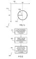
- Figures 1a , 1b and 1c display respectively a tree of components, an oriented graph derived from this tree by a method in a number of embodiments of the invention and the layout of a wallclock at the initialization of the tree.
- Said tree of components can be directly expressed in a language for developing interactive applications, such as the Djnn language. It may also be built by modeling an existing application on the form of a tree of components which comprises control structure components.
- Figure 1 a display a tree 100a of subcomponents of an interactive application in an embodiment of the invention. More generally, an application can be considered as a large component, and the principles of the invention apply to both components that may be re-integrated within larger components or application, and applications. In the remaining of the specification, the symbol “/" will be representative of a parent-child relationship in the tree, between a component and one of its subcomponents.
- the component “wallclock” 110a has three subcomponents “control” 120a, "graphics” 130a and “connector” 160a.
- the component "control" 120a has:
- the component “graphics” 130a has three subcomponents circle “bkg” 131 a, rotation “r” 132a with one subcomponent angle 134a, and line “seconds” 133a.
- a second component connector 160a has an input subcomponent 161 a that references the component "mult”/result 127a and an output subcomponent 132a that references the component “r/angle” 134a: when the connector 160a is active, the value of "mult/result” 127a is copied into “r/angle” 134a upon each modification of "mult/result” 127a.
- the component "graphics" 130a and its subcomponent define the layout of the component "wallclock” 110a: it displays a wallclock comprising a circle and a needle of seconds, represented by a line drawn by the component 133a, with a rotation whose angle is defined by the component angle 134a.
- Each second a tick of the clock occurs, and the component 121 a is activated.
- the binding 150a is active, upon each activation of the component 121 a the component 122a is activated.
- every second the component incr "incr" 122a is activated, and its state 124a is incremented. Incrementing the state of the component 124a activates it.
- the activation of component 123a multiplies the value of the left component by the value of the right component, which is always 6, into the result component 127a. This activates the component 127a.
- the connector 160a While the connector 160a is active, the value of result 127a is copied into the component angle 134a. This activates the component angle 134a, which in turn updates the layout of the application by turning the needle of seconds.
- the combination of components including control components such as bindings and connectors makes the angle of the needle be updated every second. Since the clock ticks 60 times per minute, and the result that will be copied into the angle value is multiplied by 6, the needle will turn every minute by 360°.
- One of the objectives of the invention is to be able to demonstrate a set of properties of a component.
- the properties can be : that the needle of seconds is always visible, that the needle of seconds is updated every seconds, and that it makes a full turn in 60 seconds.
- the tree 100a is created by an interpreter parsing an XML file, which may for example comprise the following XML lines:
- Each component and subcomponent is defined by an XML markup, types of components being defined by the type of the markup and attributes of the components being initialized with the values of the attributes of the markup.
- the structure of the tree is directly derived from the structure of the markups. For example, the root node “wallclock” will create the component 110a, and its three children "control", “graphics” and connector will respectively be parsed for creating subcomponents 120a, 130a and 160a.
- the components can be initialized with a standard class "component", or a more specialized component class such as a connector component if the name of the class is known by the interpreter.
- the tree 100a can be created by executing lines of codes in an environment of executions that support Djnn functions and libraries.
- Java lines of code can be used for creating the tree 100a in a Java environment with Djnn libraries:
- the "new" keyword is used for creating a component or a subcomponent.
- its father is provided as the first argument of the constructor of the Java class.
- Others parameters for initializing the values of the attributes of the components and subcomponents are provided to the constructor.
- the present invention discloses both a method for defining and a method for verifying a property of a component comprising a tree of subcomponents.
- Each of these methods rely on creating an oriented graph comprising subcomponents of the tree.
- Properties can be defined for each component in a tree of components, therefore allowing to define properties at various levels of detail while expressing said properties in a language close to the language used for defining components.
- Figure 1b displays an example of oriented graph created by a method in an embodiment of the invention, said oriented graph being built in accordance to the tree 100a.
- the oriented graph 100b comprises the components and subcomponents 110a, 120a, 121 a, 122a, 123a, 124a, 125a, 126a, 127a, 130a, 131 a, 132a, 133a, 134a, 140a, 141 a, 142a, 150a, 151 a, 152a, 160a, 161 a and 162a of the tree 100a.
- an oriented graph created by a method according to the invention comprises only a subset of the subcomponents of the tree. For example, it may comprise all subcomponents except the control structure subcomponents 140a, 150a and 160a.
- the oriented graph 100b comprises a plurality of arcs. Some of them, for example the arcs 120b, 150b, 160b, correspond to a child relationships between the component and subcomponents. Other arcs represent couplings. For example the arc 153b is created according to the binding 150a, the arc 143b is created according to the connector 140a, and the arc 163b is created according to the connector 160a.
- arcs of the graph thus includes all arcs of the tree; arcs of the graph also includes arcs modeling the coupling created by bindings (when a binding is defined between a components S to a component A, then an arc is added to the graph between S and A). Bindings to be considered can be sub-components of a complex component. In the case of a connector between an input and output sub-components, an arc is added from input to output sub-components.
- Figure 1c displays the layout of a wallclock at the initialization of the tree 100a.
- the clock 110c is displayed in a frame of reference of an application comprising a vertical axis 101c and an horizontal axis 102c.
- the origin of the frame of reference is located in the top-left corner of application or screen.
- the wallclock 110c is represented by a circle 131c and a line 133c that represents the needle of seconds, which respectively correspond to subcomponents 131 a and 133a.
- the figure 2 displays a method for defining a property of an interactive component in a number of embodiments of the invention.
- the method 200 applies on an interactive component, said interactive component being represented as a tree of child components, said tree of child components comprising a control structure child component defining a coupling between a first child component and a second child component, the second child component being activated upon the activation of the first child component.
- the method applies for example to the component 100a, or more generally on any interactive component disclosed in European Application n° 15305949.8 filed by the applicant the same day.
- the method 200 comprises a step 210 of creating an oriented graph representative of the interactive component, nodes of which comprise the first child component and the second child component.
- Examples of methods for creating an oriented graph notably comprise creating a first arc between the interactive component and a child of said component, and creating a second arc between the first child and the second child, and examples of said method are described with reference to figure 1 for creating the oriented graph 100b.
- the method further comprises a step 220 of obtaining a second graph, representative of the property.
- Obtaining said a second graph may be performed by retrieving a graph from a library of prototype graphs associated to different properties.
- the second graph may also be created for verifying the property.
- said second graph may be obtained by adapting a prototype graph representative of a type of properties.
- the second graph is also an oriented graph.
- the construction of the second graph depends on the property to define. For example, graph invariants can be created for proving the static interface of components. This is required when different developers build or evolve interactive components in parallel and then combine them. This verification ensures that a component offers a static interface as previously defined in its specification.
- the static interface of a component is called signature.
- the signature of a component is defined by the set of its sub components.
- the signature of a widget can be made of 2 sub-components: width and height.
- the signature of a rectangle is made of position sub-component (including sub-sub components X and Y), size sub-component (including sub-sub-components width and height), size of rounded corner sub-components (including horizontal and vertical size), mouse pressed event sub-component (including sub-sub-components position X and Y), mouse release event sub component, mouse move event sub-component (including sub sub components X and Y), mouse enter event sub-component and mouse leave event sub-component.
- a property related to a static interface of a component can be translated into a second graph.
- the graph invariant is made of a root component and its sub-components composing the interface.
- Said second graph can also be used for defining properties relative to correct formation of the application.
- bindings refer to defined source and action sub-components (property 1)
- Switches contains at least one sub-component (property 2)
- FSMs contain states and transitions such that at least one transition allows to reach a state (property 3).
- property 1 can be translated in a second graph made of component source and component action and an arc from component action to component source.
- the second graph is related to the existence of a control flow connections between 2 components. This is required when different developers build or evolve interactive components in parallel and then combine them. Such an invariant may be defined by defining a path from a component A to a component S.
- the method 200 further comprises a step 230 for verifying one of a presence and an absence of the second graph in the first oriented graph.
- Examples of properties verified by the presence of the second graph include properties on the layout of the components. For example, the presence of a second graph comprising a rectangle and an opacity component on its left can be used for proving that an opaque rectangle exists within the component. They also include properties relative to the correct formation of the interactive component. For example, proving that a FSM is correctly formed can be proven by a second graph, representative of a well-formed FSM is present within the first oriented graph.
- Examples of properties verified by the absence of the second graph include for example properties relative to the layout of components.
- the absence of a second graph comprising a rectangle and a graphical component on its right is sufficient to prove that the rectangle is not masked by another component.
- the presence or absence of a second graph can also be defined conditional upon values of attributes of the nodes of said second graph. For example, proving that a rectangle is not masked by another component can be performed even if a second graph comprising the rectangle and a second component on its right, if the borders of said second component do not overlap with the borders of the rectangle. This can be verified by comparing the attributes relative to the size and position of the second component to the parameters relative to the size and position of the rectangle.
- values of attributes can also be tested in relation to a context of execution of the interactive component.
- the verification of properties relative to the layout of the component can be verified using the resolution of the screen on which the component will be displayed in parameter.
- the use of the arcs that created by the couplings between components permit to verify not only the immediate value of parameters, but also if these value are subject to change. For example, when verifying the opacity of a rectangle, the absence of an arc representative of a coupling directed to the value of opacity is sufficient to prove that this value will not change whatever the context of execution and inputs.
- the method 200 is executed during the development of an interactive component or application, in order to define precise properties that shall be verified afterwards, for example in non-regression tests or for communicating specifications in a development team.
- Graph invariants may be for example defined by a user or automatically.
- the method 200 can be executed by during the session of execution of the component or application. This is for example the case for invariants that can be defined automatically, for example invariants relative to the correct formation of the application
- a property can be verified by verifying a plurality of sub-properties. For example a property stating that a rectangle is always visible can be proven by proving the following sub-properties:
- Sub-properties can also relate to different elements that characterize the property. For example, for proving that a clock comprises three needles that represent respectively hours, minutes, seconds, it may be possible to verify that:
- the method thus advantageously permits to demonstrate abstract properties of an interactive component.
- the method applies to software written in a language for interactive applications structure with a tree of components and components representative of couplings.
- the Djnn framework is an example of framework allowing to write a program in this form. It is therefore a straightforward task to obtain the tree of components.
- a software is written in a language that do not natively express recursive components and interactions.
- the method 200 comprises, beforehand step 210, a preliminary step of creating a tree of components which comprises at least one component defining a coupling between two components.
- Said preliminary step consists in modeling software or applications which are not natively expressed as component and interactions into an interactive component similar to those discloses in European Application n° 15305949.8 .
- These embodiments advantageously permit to use the possibilities of verification of properties disclosed by the application to a larger number of languages and software.
- the method used in the preliminary step for modeling software or application into a tree of components depend on the characteristics of said software or application, for example the language there are written in.
- the method is used to prove non-regression during the development of an application.
- the method is used for validating specifications of software.
- the method is used for verifying that a property is verified in a context of execution of the application.
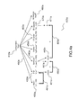
- Figure 3 displays a subpart of a tree of an interactive component in a number of embodiment of the invention.
- the sub-set of components impacted by another component is made of the components on which the color defined by the color component is applied.
- source component component that defines an property to be applied to other components.
- impacted components the sub-set of component on which the property is applied.
- the set of impacted components is made of components of the tree 300 being following sibling (younger brothers) of the source component and their descendants until another similar source component is defined.
- component 320 labeled C12 is the source component.
- the component 320 is a color component, that defines the color of all impacted components.
- Impacted components are following sibling components of the component 320: component 330, labeled C13 and component 340, labeled C14, and their descendants: descendants of component 330are components 331, 332 and 333, respectively labeled C131, C132 and C133; descendants of component 340 are components 341 and 342, respectively labeled C141 and C142.
- the set of components impacted by component 320 is the set of components 350.
- This example demonstrates how a components applies only to a subset of components of the tree, in a number of embodiments of the invention.
- the components on which an effect such as a color applies depend in part of the relative position of components.
- some properties are checked according to the relative position of components.
- Figures 4a and 4b display respectively an oriented graph created from a tree of components that comprises a rectangle whose opacity increases, and some properties that can be verified on this graph by a method according to the invention.
- Figure 4a displays an oriented graph created from a tree of components that comprises a rectangle whose opacity increases.
- the tree of components is for example created by parsing the XML file below:
- components when displaying a tree of components, components are traversed in a depth-first order, from left to right, and characteristic of a component may apply to sibling on its right.
- the rectangle 480a will have the color defined by component 460a and the opacity defined by component 470a.
- the oriented graph 400a comprises all these components.
- it comprises arcs, that are created by parent-child relationship of the components and subcomponents in the tree, for example the arc 490a.
- arc is created for each father-child relationship in the tree, and is oriented from the father to the child.
- the oriented graph comprises arcs created from control structure components, which are representative of couplings between components.
- the edge 491 a from subcomponent 420a to subcomponent 430a is created from a binding
- edge 492a from subcomponent 431 a to subcomponent 441 a, and edge 493a from subcomponent 442a to subcomponent 471 a are both created from connectors.
- the behavior of the component is the following: upon each tick of clock 420a, the binding represented by arc 491 a activates increment 430a, which increments the state component 431 a. This activates subcomponent 431 a.
- the connector represented by arc 492a copies the value of state 461 a into the subcomponent I 441a. This activates the subcomponent 440a.
- the formula is applied on the value of I 441a and the result is assigned to subcomponent result 442a. This activates subcomponent 442a, and the connector represented by arc 493a copies the value of result into a, which modifies the opacity of the rectangle.
- opacity progressively diminishes, since it is equal to 1-i/100, and i is incremented upon each tick of the clock. Thus, the rectangle progressively vanishes.
- Figure 4b displays the scope of some properties that can be verified on this graph by a method according to the invention.
- This verification can for example be performed by a method 200 in a number of embodiments of the invention.
- the property that will be verified is that a rectangle is always visible, with an opacity greater than 0,5, on a scale ranging from 0 to 1.
- this property is decomposed into the conjunction of several sub-properties. Verifying the property consists in verifying the conjunction of sub-properties.
- sub-properties are: 1/ existence of a rectangle ; 2/ no graphical shape masks the rectangle; 3/ opacity applicable to the rectangle is greater than 0.5; 4/ value of the opacity component is not subject to change
- property 1/ is translated into a graph representative of said property 1/ and this graph is then checked against the graph of the component.
- Graph of property 1/ is a graph made of a unique component: the rectangle.
- Check of the graph property 1/ against the graph of the component consists in verifying that the invariant graph is a sub-graph of the graph of the component (checking by this way the existence of the rectangle).
- a second condition 402b can be defined, that no graphical shape masks the rectangle. If drawing the subcomponents is performed from the left to the right, this consists in verifying that no rectangle exists on the right of rectangle 480a. This property is verified by the oriented graph 400a. However, it would not be verified in an oriented graph 400b comprising a rectangle 480b at the right of rectangle 480a. In a number of embodiments of the invention, the condition can however be met if the rectangle 480b does not overlap with rectangle 480a.
- the graph representative of this second property is made of a graphical shape component and the property is verified by checking whether the graph of property 2/ is not a sub graph of the following sibling sub-graph of the rectangle.
- a third condition 403b can be defined, that the opacity applicable to the rectangle is greater than 0.5.
- This condition is met by the oriented graph 400b.
- the graph of this 3 rd property is made of a unique component opacity. It is verified by searching in the graph this component with an opacity value greater or equal to 0.5 and verifying that the rectangle component is one of its following sibling sub-components.
- a fourth condition 404b can be defined, that the value of the opacity is not subject to change. In the graph 400a and this condition is not met, since the connector 404b modifies the value of the opacity.
- the graph of the property 4/ is made of the opacity and clock components, and an arc between clock component and opacity component.
- the verification consists in checking whether this invariant graph is a sub-graph of the transitive closure of the graph.
- the invention can be used in by various actors in various system engineering processes.
- the invention can be used during the independent development of interactive components: developers use the invention during the design of their components as a method for verification of properties fulfilled by said components. Properties can be defined at any time during the design of said components, including before the design, during the design when additional requirements are identified, or when a component is being debugged and an error is traced back to an implicit requirement that was not fulfilled and that must be made explicit to avoid regressions.
- Integrators may define and check additional properties for the components they wish to reuse as sub-components of their own components, especially when said properties are essential to the proper work of their own components. Once the properties are defined for it, the integrators can also decide to replace a sub-component by another and check that the new sub-component also holds the properties.
- the two previous methods can be grouped in a development environment aimed at defining and producing interactive software.
- Various actors of the specification, development and validation of a software product can produce in parallel a collection of components and component properties, with the collective goal that their work results in a software product in which all defined properties are fulfilled.
- the development environment can maintain a list of properties that are not yet fulfilled, by constantly monitoring changes to components and re-checking properties.
- the invention can also be used to support a part of certification process.
- the invention can be used to provide "evidence that the system is complete and correct with respect to its requirements” and to support "determination of which code, software requirements or software architecture satisfy the next higher level of software requirements”.
- the invention can be used in a specification and acquisition process.
- a company can create a software prototype as a collection of software components iteratively, said prototype being destined to capture its requirements. It can then formulate properties on the significant software components that constitute said prototypes, and deliver the resulting collection of properties to a third party vendor from which it desires to acquire an industrial version of the prototype.
- the software vendor delivers the resulting product, the company can check that the properties are fulfilled. This ensures that both the benefits of external sourcing and the benefits of a specification are present in the final product.
- the invention can be used in compilers of interactive software, where said interactive software is written in a language that implements the interactive component model used in the invention.
- a compiler can check the properties of components and emit errors when properties are not fulfilled.
- the invention can be used in tools dedicated to unit tests, where the definition of component properties would be a sub-set of the language provided to the programmers of unit tests. Said unit tests could therefore combine the simulation of an execution environment and the checking of properties.
- Another way to use the invention is to use the invention by modeling as a collection of interactive components all or part of the environment in which a software component is destined to be used, then to combine said model and said software component in a larger component, then to define and check properties on said larger component. This allows for instance to check that a software component is fit for a task or a user activity, by modeling said task or activity. The same method can also be used for checking compatibility of a software component with a hardware platform.
- An alternative use of the invention is to define properties of the environment in which a software component must be used, so as to document the conditions of reuse of said software component. For instance, it is possible to state in a property that a graphical button must be used in an environment in which at least one pointer is available. Engineers or users of said graphical button can then obtain a model of the computer and operating system in which they wish to reuse said button, and check if the property is held by said model of the computer and operating system.
- An alternative use of the invention is in the run-time software execution system that is used to execute interactive components.
- Said execution system can dynamically check properties on components that it receives from its environment, for example when loading components from files, or receiving them from network connections, or creating them upon the detection of hardware devices or other elements of the execution context.
- said execution system can provide an application-programming interface (API) that allows programmers to define properties and to define actions to be performed on dynamically created components. This allows programmers to create automatic adaptation mechanisms in their software.
- API application-programming interface
- a repository of properties can be defined.
- the vendor of a development environment can propose a collection of properties that are deemed necessary for components to execute properly, and suggest programmers to check said properties on their components.
- More specific properties can be defined for specific classes of components or specific application domains.
- regulatory bodies of the civil aviation sector can define interaction-oriented properties that specific interactive aircraft cockpit equipments must possess so as to be used for transporting passengers.
- the repository can also offers means for searching, classifying, editing and modifying the properties according to these criteria.
- component properties can be used as a method for indexing and retrieving interactive components in a repository of components.
- Said repository could check the contents of a repository of properties against any component uploaded by a vendor, index said component with all those properties that it holds, and then allow users to retrieve components by selecting the desired properties, or to navigate its contents according to the available properties.
Landscapes
- Engineering & Computer Science (AREA)
- Theoretical Computer Science (AREA)
- Software Systems (AREA)
- General Engineering & Computer Science (AREA)
- Physics & Mathematics (AREA)
- General Physics & Mathematics (AREA)
- Computer Hardware Design (AREA)
- Quality & Reliability (AREA)
- Human Computer Interaction (AREA)
- Stored Programmes (AREA)
Priority Applications (5)
| Application Number | Priority Date | Filing Date | Title |
|---|---|---|---|
| EP15305950.6A EP3106990A1 (fr) | 2015-06-19 | 2015-06-19 | Procédé, logiciel et unité de traitement permettant de vérifier les propriétés de composants interactifs |
| US15/186,073 US10866878B2 (en) | 2015-06-19 | 2016-06-17 | Method, software and processing unit for verifying properties of interactive components |
| EP16305747.4A EP3106991A1 (fr) | 2015-06-19 | 2016-06-20 | Procédé, logiciel et unité de traitement permettant de vérifier les propriétés de composants interactifs |
| CN201610444712.1A CN106445802B (zh) | 2015-06-19 | 2016-06-20 | 用于验证交互式组件的属性的方法、软件和处理单元 |
| HK17105255.0A HK1231598A1 (en) | 2015-06-19 | 2017-05-24 | A method, software and processing unit for verifying properties of interactive components |
Applications Claiming Priority (1)
| Application Number | Priority Date | Filing Date | Title |
|---|---|---|---|
| EP15305950.6A EP3106990A1 (fr) | 2015-06-19 | 2015-06-19 | Procédé, logiciel et unité de traitement permettant de vérifier les propriétés de composants interactifs |
Publications (1)
| Publication Number | Publication Date |
|---|---|
| EP3106990A1 true EP3106990A1 (fr) | 2016-12-21 |
Family
ID=53502583
Family Applications (2)
| Application Number | Title | Priority Date | Filing Date |
|---|---|---|---|
| EP15305950.6A Withdrawn EP3106990A1 (fr) | 2015-06-19 | 2015-06-19 | Procédé, logiciel et unité de traitement permettant de vérifier les propriétés de composants interactifs |
| EP16305747.4A Ceased EP3106991A1 (fr) | 2015-06-19 | 2016-06-20 | Procédé, logiciel et unité de traitement permettant de vérifier les propriétés de composants interactifs |
Family Applications After (1)
| Application Number | Title | Priority Date | Filing Date |
|---|---|---|---|
| EP16305747.4A Ceased EP3106991A1 (fr) | 2015-06-19 | 2016-06-20 | Procédé, logiciel et unité de traitement permettant de vérifier les propriétés de composants interactifs |
Country Status (4)
| Country | Link |
|---|---|
| US (1) | US10866878B2 (fr) |
| EP (2) | EP3106990A1 (fr) |
| CN (1) | CN106445802B (fr) |
| HK (1) | HK1231598A1 (fr) |
Cited By (1)
| Publication number | Priority date | Publication date | Assignee | Title |
|---|---|---|---|---|
| CN109445767A (zh) * | 2018-11-13 | 2019-03-08 | 上海宝尊电子商务有限公司 | 一种应用于多终端的新型响应式导航设计实现方法 |
Families Citing this family (6)
| Publication number | Priority date | Publication date | Assignee | Title |
|---|---|---|---|---|
| CN108804299B (zh) * | 2017-04-26 | 2023-04-07 | 腾讯科技(深圳)有限公司 | 应用程序异常处理方法及装置 |
| EP3404535A1 (fr) * | 2017-05-15 | 2018-11-21 | Ecole Nationale de l'Aviation Civile | Procédé et appareil de traitement de code |
| CN108710726B (zh) * | 2018-04-16 | 2022-03-15 | 西安飞机工业(集团)有限责任公司 | 一种基于唯一设计数据源的飞机构型控制方法 |
| JP7443692B2 (ja) * | 2019-07-29 | 2024-03-06 | 株式会社デンソーウェーブ | 産業用制御装置の入力モジュール |
| US12197843B2 (en) * | 2020-03-30 | 2025-01-14 | Oracle International Corporation | Automatic layout of elements in a process flow on a 2-D canvas based on representations of flow logic |
| CN113504868B (zh) * | 2021-06-22 | 2025-01-03 | 联通(广东)产业互联网有限公司 | 一种产品数据结构配置方法和系统 |
Citations (1)
| Publication number | Priority date | Publication date | Assignee | Title |
|---|---|---|---|---|
| US20130055221A1 (en) * | 2011-08-26 | 2013-02-28 | Fujitsu Limited | Detecting Errors in Javascript Software Using a Control Flow Graph |
Family Cites Families (6)
| Publication number | Priority date | Publication date | Assignee | Title |
|---|---|---|---|---|
| US6108698A (en) * | 1998-07-29 | 2000-08-22 | Xerox Corporation | Node-link data defining a graph and a tree within the graph |
| US7620946B2 (en) * | 2003-05-05 | 2009-11-17 | Jeffry Thomas Russell | Program slicing for codesign of embedded systems |
| US20080301553A1 (en) * | 2007-05-04 | 2008-12-04 | Microsoft Corporation | Verifying compliance of user interfaces with desired guidelines |
| JP2013125441A (ja) | 2011-12-15 | 2013-06-24 | Toyota Infotechnology Center Co Ltd | ソフトウェア管理システム、ソフトウェア検証装置、ソフトウェア管理方法 |
| US9098620B2 (en) * | 2012-05-12 | 2015-08-04 | Palo Alto Research Center Incorporated | System and method for parallel model checking utilizing parallel structured duplicate detection |
| CN103312592B (zh) | 2013-06-03 | 2016-12-28 | 政和科技股份有限公司 | 一种在网页上批量向即时通信客户端发送信息的方法 |
-
2015
- 2015-06-19 EP EP15305950.6A patent/EP3106990A1/fr not_active Withdrawn
-
2016
- 2016-06-17 US US15/186,073 patent/US10866878B2/en active Active
- 2016-06-20 EP EP16305747.4A patent/EP3106991A1/fr not_active Ceased
- 2016-06-20 CN CN201610444712.1A patent/CN106445802B/zh active Active
-
2017
- 2017-05-24 HK HK17105255.0A patent/HK1231598A1/en unknown
Patent Citations (1)
| Publication number | Priority date | Publication date | Assignee | Title |
|---|---|---|---|---|
| US20130055221A1 (en) * | 2011-08-26 | 2013-02-28 | Fujitsu Limited | Detecting Errors in Javascript Software Using a Control Flow Graph |
Non-Patent Citations (6)
| Title |
|---|
| ABRIAL: "The B-Book - Assigning Programs to Meanings", 2005 |
| BAIER ET AL.: "Principles of model-checking,", MIT PRESS |
| COUSOT ET AL.: "Proc. ACM POPL'77", 1977, ACM, article "Abstract interpretation: A unified lattice model for static analysis of programs by construction or approximation of fixpoints", pages: 238 - 252 |
| MANUEL SOUSA ET AL: "Formal Verification of Safety-Critical User Interfaces: A Space System Case Study", 8 May 2014 (2014-05-08), pages 62 - 67, XP055172416, Retrieved from the Internet <URL:http://www.chi-med.ac.uk/publicdocs/WP217.pdf> [retrieved on 20150226] * |
| MEYER, B. APPLYING: "Computer", vol. 25, October 1992, IEEE, article "Design by Contract", pages: 40 - 51 |
| THIMBLEBY, H.; GOW., J.: "Proc. EIS 2007", 2008, SPRINGER, article "Applying graph theory to interaction design", pages: 501 - 518 |
Cited By (1)
| Publication number | Priority date | Publication date | Assignee | Title |
|---|---|---|---|---|
| CN109445767A (zh) * | 2018-11-13 | 2019-03-08 | 上海宝尊电子商务有限公司 | 一种应用于多终端的新型响应式导航设计实现方法 |
Also Published As
| Publication number | Publication date |
|---|---|
| US20160371168A1 (en) | 2016-12-22 |
| CN106445802B (zh) | 2020-08-11 |
| HK1231598A1 (en) | 2017-12-22 |
| CN106445802A (zh) | 2017-02-22 |
| US10866878B2 (en) | 2020-12-15 |
| EP3106991A1 (fr) | 2016-12-21 |
Similar Documents
| Publication | Publication Date | Title |
|---|---|---|
| US10866878B2 (en) | Method, software and processing unit for verifying properties of interactive components | |
| Campos et al. | Supporting the analysis of safety critical user interfaces: an exploration of three formal tools | |
| US20200210158A1 (en) | Automated or machine-enhanced source code debugging | |
| Markopoulos | A compositional model for the formal specification of user interface software | |
| CN103377128A (zh) | 用于Web应用的竞争检测的方法和系统 | |
| Oliveira et al. | State of the art on formal methods for interactive systems | |
| Völter | The design, evolution, and use of kernelf: An extensible and embeddable functional language | |
| Bombarda et al. | ASMETA tool set for rigorous system design | |
| Abadi et al. | Verifying parallel code after refactoring using equivalence checking | |
| Cammaerts et al. | Assessing the value of incomplete deadlock verification in Model-Driven Engineering | |
| Singh et al. | F3FLUID: A formal framework for developing safety‐critical interactive systems in FLUID | |
| Yang | A simulation framework for the validation of Event-B specifications | |
| Harrison et al. | Balancing the formal and the informal in user-centred design | |
| Arcaini et al. | Addressing usability in a formal development environment | |
| Canny et al. | Model-based testing of post-wimp interactions using object oriented petri-nets | |
| HK1231987A1 (en) | A method, software and processing unit for verifying properties of interactive components | |
| Straszak et al. | Model-driven acceptance test automation based on use cases | |
| Pimenta | Automated specification-based testing of graphical user interfaces | |
| Vilhunen | User interface test automation for an Android application | |
| Simko et al. | Formal verification of annotated textual use-cases | |
| Turner et al. | SeqCheck: a model checking tool for interactive systems | |
| Strippoli | VoxLogicA UI: Supporting declarative medical image analysis | |
| Margaria et al. | Leveraging Applications of Formal Methods, Verification and Validation. Modeling: 8th International Symposium, ISoLA 2018, Limassol, Cyprus, November 5-9, 2018, Proceedings, Part I | |
| Ribeiro et al. | A formal framework for the development of concurrent object-based systems | |
| Fayollas et al. | Supporting the analysis of safety critical user interfaces: An Exploration of Three Formal Tools |
Legal Events
| Date | Code | Title | Description |
|---|---|---|---|
| PUAI | Public reference made under article 153(3) epc to a published international application that has entered the european phase |
Free format text: ORIGINAL CODE: 0009012 |
|
| AK | Designated contracting states |
Kind code of ref document: A1 Designated state(s): AL AT BE BG CH CY CZ DE DK EE ES FI FR GB GR HR HU IE IS IT LI LT LU LV MC MK MT NL NO PL PT RO RS SE SI SK SM TR |
|
| AX | Request for extension of the european patent |
Extension state: BA ME |
|
| STAA | Information on the status of an ep patent application or granted ep patent |
Free format text: STATUS: THE APPLICATION IS DEEMED TO BE WITHDRAWN |
|
| 18D | Application deemed to be withdrawn |
Effective date: 20170622 |
|
| REG | Reference to a national code |
Ref country code: HK Ref legal event code: DE Ref document number: 1231598 Country of ref document: HK |
|
| REG | Reference to a national code |
Ref country code: HK Ref legal event code: WD Ref document number: 1231598 Country of ref document: HK |