EP3107112B1 - Kontaktsystem eines schutzschalters, sowie schutzschalter - Google Patents
Kontaktsystem eines schutzschalters, sowie schutzschalter Download PDFInfo
- Publication number
- EP3107112B1 EP3107112B1 EP16173873.7A EP16173873A EP3107112B1 EP 3107112 B1 EP3107112 B1 EP 3107112B1 EP 16173873 A EP16173873 A EP 16173873A EP 3107112 B1 EP3107112 B1 EP 3107112B1
- Authority
- EP
- European Patent Office
- Prior art keywords
- moveable contact
- circuit breaker
- moveable
- shaft
- contact arm
- Prior art date
- Legal status (The legal status is an assumption and is not a legal conclusion. Google has not performed a legal analysis and makes no representation as to the accuracy of the status listed.)
- Active
Links
Images


Classifications
-
- H—ELECTRICITY
- H01—ELECTRIC ELEMENTS
- H01H—ELECTRIC SWITCHES; RELAYS; SELECTORS; EMERGENCY PROTECTIVE DEVICES
- H01H3/00—Mechanisms for operating contacts
- H01H3/32—Driving mechanisms, i.e. for transmitting driving force to the contacts
- H01H3/46—Driving mechanisms, i.e. for transmitting driving force to the contacts using rod or lever linkage, e.g. toggle
-
- H—ELECTRICITY
- H01—ELECTRIC ELEMENTS
- H01H—ELECTRIC SWITCHES; RELAYS; SELECTORS; EMERGENCY PROTECTIVE DEVICES
- H01H77/00—Protective overload circuit-breaking switches operated by excess current and requiring separate action for resetting
- H01H77/02—Protective overload circuit-breaking switches operated by excess current and requiring separate action for resetting in which the excess current itself provides the energy for opening the contacts, and having a separate reset mechanism
- H01H77/10—Protective overload circuit-breaking switches operated by excess current and requiring separate action for resetting in which the excess current itself provides the energy for opening the contacts, and having a separate reset mechanism with electrodynamic opening
- H01H77/102—Protective overload circuit-breaking switches operated by excess current and requiring separate action for resetting in which the excess current itself provides the energy for opening the contacts, and having a separate reset mechanism with electrodynamic opening characterised by special mounting of contact arm, allowing blow-off movement
- H01H77/105—Protective overload circuit-breaking switches operated by excess current and requiring separate action for resetting in which the excess current itself provides the energy for opening the contacts, and having a separate reset mechanism with electrodynamic opening characterised by special mounting of contact arm, allowing blow-off movement whereby the blow-off movement unlatches the contact from a contact holder
-
- H—ELECTRICITY
- H01—ELECTRIC ELEMENTS
- H01H—ELECTRIC SWITCHES; RELAYS; SELECTORS; EMERGENCY PROTECTIVE DEVICES
- H01H3/00—Mechanisms for operating contacts
- H01H3/54—Mechanisms for coupling or uncoupling operating parts, driving mechanisms, or contacts
-
- H—ELECTRICITY
- H01—ELECTRIC ELEMENTS
- H01H—ELECTRIC SWITCHES; RELAYS; SELECTORS; EMERGENCY PROTECTIVE DEVICES
- H01H1/00—Contacts
- H01H1/12—Contacts characterised by the manner in which co-operating contacts engage
- H01H1/14—Contacts characterised by the manner in which co-operating contacts engage by abutting
- H01H1/24—Contacts characterised by the manner in which co-operating contacts engage by abutting with resilient mounting
-
- H—ELECTRICITY
- H01—ELECTRIC ELEMENTS
- H01H—ELECTRIC SWITCHES; RELAYS; SELECTORS; EMERGENCY PROTECTIVE DEVICES
- H01H3/00—Mechanisms for operating contacts
- H01H3/02—Operating parts, i.e. for operating driving mechanism by a mechanical force external to the switch
- H01H3/16—Operating parts, i.e. for operating driving mechanism by a mechanical force external to the switch adapted for actuation at a limit or other predetermined position in the path of a body, the relative movement of switch and body being primarily for a purpose other than the actuation of the switch, e.g. for a door switch, a limit switch, a floor-levelling switch of a lift
-
- H—ELECTRICITY
- H01—ELECTRIC ELEMENTS
- H01H—ELECTRIC SWITCHES; RELAYS; SELECTORS; EMERGENCY PROTECTIVE DEVICES
- H01H3/00—Mechanisms for operating contacts
- H01H3/32—Driving mechanisms, i.e. for transmitting driving force to the contacts
- H01H3/38—Driving mechanisms, i.e. for transmitting driving force to the contacts using spring or other flexible shaft coupling
-
- H—ELECTRICITY
- H01—ELECTRIC ELEMENTS
- H01H—ELECTRIC SWITCHES; RELAYS; SELECTORS; EMERGENCY PROTECTIVE DEVICES
- H01H9/00—Details of switching devices, not covered by groups H01H1/00 - H01H7/00
- H01H9/20—Interlocking, locking, or latching mechanisms
-
- H—ELECTRICITY
- H01—ELECTRIC ELEMENTS
- H01H—ELECTRIC SWITCHES; RELAYS; SELECTORS; EMERGENCY PROTECTIVE DEVICES
- H01H1/00—Contacts
- H01H1/12—Contacts characterised by the manner in which co-operating contacts engage
- H01H1/14—Contacts characterised by the manner in which co-operating contacts engage by abutting
- H01H1/22—Contacts characterised by the manner in which co-operating contacts engage by abutting with rigid pivoted member carrying the moving contact
- H01H1/221—Contacts characterised by the manner in which co-operating contacts engage by abutting with rigid pivoted member carrying the moving contact and a contact pressure spring acting between the pivoted member and a supporting member
- H01H1/226—Contacts characterised by the manner in which co-operating contacts engage by abutting with rigid pivoted member carrying the moving contact and a contact pressure spring acting between the pivoted member and a supporting member having a plurality of parallel contact bars
-
- H—ELECTRICITY
- H01—ELECTRIC ELEMENTS
- H01H—ELECTRIC SWITCHES; RELAYS; SELECTORS; EMERGENCY PROTECTIVE DEVICES
- H01H1/00—Contacts
- H01H1/12—Contacts characterised by the manner in which co-operating contacts engage
- H01H1/14—Contacts characterised by the manner in which co-operating contacts engage by abutting
- H01H1/22—Contacts characterised by the manner in which co-operating contacts engage by abutting with rigid pivoted member carrying the moving contact
- H01H1/221—Contacts characterised by the manner in which co-operating contacts engage by abutting with rigid pivoted member carrying the moving contact and a contact pressure spring acting between the pivoted member and a supporting member
- H01H2001/223—Contacts characterised by the manner in which co-operating contacts engage by abutting with rigid pivoted member carrying the moving contact and a contact pressure spring acting between the pivoted member and a supporting member using a torsion spring
-
- H—ELECTRICITY
- H01—ELECTRIC ELEMENTS
- H01H—ELECTRIC SWITCHES; RELAYS; SELECTORS; EMERGENCY PROTECTIVE DEVICES
- H01H2205/00—Movable contacts
- H01H2205/002—Movable contacts fixed to operating part
-
- H—ELECTRICITY
- H01—ELECTRIC ELEMENTS
- H01H—ELECTRIC SWITCHES; RELAYS; SELECTORS; EMERGENCY PROTECTIVE DEVICES
- H01H3/00—Mechanisms for operating contacts
- H01H3/22—Power arrangements internal to the switch for operating the driving mechanism
- H01H3/30—Power arrangements internal to the switch for operating the driving mechanism using spring motor
-
- H—ELECTRICITY
- H01—ELECTRIC ELEMENTS
- H01H—ELECTRIC SWITCHES; RELAYS; SELECTORS; EMERGENCY PROTECTIVE DEVICES
- H01H3/00—Mechanisms for operating contacts
- H01H3/32—Driving mechanisms, i.e. for transmitting driving force to the contacts
- H01H3/34—Driving mechanisms, i.e. for transmitting driving force to the contacts using ratchet
Definitions
- the subject matter disclosed herein relates to circuit breakers and, more particularly, to a contact system of a circuit breaker.
- An electrical switching apparatus such as a circuit breaker, provides protection for electrical systems from electrical fault conditions such as, for example, current overloads, short circuits, abnormal voltage and other fault conditions.
- circuit breakers include a housing and an operating mechanism which opens separable electrical contacts to interrupt the flow of current through the conductors of an electrical system in response to certain fault conditions.
- SE 175 730 C1 describes a circuit breaker with contact arms from which one is pivoted to open or close the circuit. A trip shaft is arranged which locks the closed position and at which a bended longitudinal plate slides along when one contact arm moves.
- US 6437670 B1 describes a magnetic release system for a circuit breaker with a first current level at which a release lever prevents movement of a contact structure and a second current level at which the release lever releases the contact structure.
- the drawback of having the contacts clamped or otherwise maintained in a tight closed condition is that the contacts may not be able to open quickly at the short circuit current level that the circuit breaker is rated for. Therefore, it is desirable to reliably disengage the contacts to the blow open condition of the circuit breaker in as rapid of a manner as possible, while ensuring that the contacts remain in the closed condition during normal operation of the circuit breaker.
- a contact system of a circuit breaker includes a fixed contact.
- the contact system also includes at least one moveable contact arm assembly comprising a moveable contact arm having a moveable contact thereon, the moveable contact arm moveable to position the moveable contact into engagement with the fixed contact to define a closed condition and out of engagement with the fixed contact to define a blow open condition.
- the contact system further includes a carrier assembly operatively coupled to the moveable contact arm.
- the contact system yet further includes a latch plate operatively coupled to the carrier assembly.
- the contact system also includes a trip shaft operatively coupled to the carrier assembly, the trip shaft having a non-circular region defining an engagement surface disposed in contact with the latch plate in the closed condition.
- the contact system further includes a biasing portion of the moveable contact arm extending from the movable contact arm, the biasing portion disposed proximate the trip shaft in the closed condition and configured to rotate the trip shaft out of engagement with the latch plate and into the blow open condition directly by an electromagnetic force on the movable contact arm; the contact system retaining the contacts in the closed condition at electromagnetic force levels lower than a threshold level and moves the circuit breaker into the blow open condition upon reaching the threshold level.
- a circuit breaker having a mechanism portion, a contact system portion and an arc chamber portion, the circuit breaker includes a first coupling member operatively coupled to a drive link of the mechanism portion, the first coupling member rotatable about a first shaft.
- the circuit breaker also includes a second coupling member pivotably coupled to the first coupling member and to a second shaft.
- the circuit breaker further includes a plurality of fixed contacts.
- the circuit breaker yet further includes a moveable contact arm assembly comprising a plurality of moveable contact arms, each of the plurality of moveable contact arms having a moveable contact disposed thereon, the moveable contact arm moveable to position each moveable contact into engagement with a respective fixed contact of the plurality of fixed contacts to define a closed condition and out of engagement with the plurality of fixed contacts to define a blow open condition.
- the circuit breaker also includes a carrier assembly operatively coupling the plurality of moveable contact arms to each other.
- the circuit breaker further includes a latch plate operatively coupled to the carrier assembly and to the second shaft.
- the circuit breaker yet further includes a trip shaft operatively coupled to the carrier assembly, the trip shaft having a non-circular region defining an engagement surface, the trip shaft disposed in contact with the latch plate in the closed condition.
- the circuit breaker also includes a biasing portion of one of the plurality of moveable contact arms extending from the movable contact arm, the biasing portion disposed proximate the engagement surface of the trip shaft in the closed condition and configured to rotate the trip shaft out of engagement with the latch plate directly by an electromagnetic force on the movable contact arm; wherein interaction of the latch plate, trip shaft, and biasing portion facilitates retention at electromagnetic force levels lower than a threshold level and moves the circuit breaker into the blow open condition upon reaching the threshold level.
- the circuit breaker includes a main mechanism portion 12, a contact system portion 14, and an arc chute portion 16.
- the contact system portion 14 includes a moveable contact arm assembly 18 that includes at least one, but typically a plurality of moveable contact arms 20.
- Each of the moveable contact arms 20 includes a moveable contact 22 disposed thereon and is positioned to be moved into an out of contact with a respective fixed contact 24.
- the connection facilitates connecting and disconnecting an electrical power source to an electrical load.
- the circuit breaker 10 is said to be in a closed condition when the moveable contact 22 and the fixed contact 24 are in contact ( FIG. 4 ).
- the circuit breaker 10 is said to be in a "blow open condition" when the moveable contact 22 and the fixed contact 24 are not in contact and spaced from each other ( FIG. 5 ).
- the blow open condition occurs in response to a short circuit event. More particularly, a threshold electromagnetic force created by a short circuit forces the contact arm(s) to swing open before the mechanism 12 has time to respond.
- the threshold electromagnetic force is related to a threshold current level.
- a lay shaft 29 remains in a first rotational position that it is in during the closed condition described above.
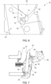
- a resetting spring around the lay shaft 29 aids in moving a carrier assembly (described in detail below), to a fully open condition ( FIG. 7 ).
- This condition may be referred to as a "trip condition.” It is to be appreciated that the trip open condition is distinct from the blow open condition. Movement to the trip condition involves the tripping system in the mechanism being activated and rotating the lay shaft 29 to bring the carrier assembly into the fully open condition.
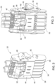
- the carrier assembly 32 includes a plurality of separation brackets 34.
- the plurality of separation brackets 34 may be independent brackets or may be formed as a uniform assembly, such as in an integrally formed or operatively coupled manner.
- two of the separation brackets referred to as a first end bracket 36 and a second end bracket 38, are integrally formed, and joined by a U-bracket 40.
- each of the brackets are disposed adjacent to at least one of the plurality of moveable contact arms 20 to separate the moveable contact arms 20.
- a first end plate 42 and a second end plate 44 are each disposed outwardly of the plurality of separation brackets 34.
- a second shaft 46 extends through the first end plate 42, the plurality of separation brackets 34, the second end plate 44, and the second coupling member 30.
- the second shaft 46 operatively couples the aforementioned components together and provides an axis about which the second coupling member 30 is rotatable about. As shown, additional shafts may be employed to further couple the components.
- the second coupling member 30 is sized at the location of coupling to the second shaft 46 to be smaller than the space between the plurality of separation brackets 34 to avoid direct contact with the separation brackets.
- at least one spacer such as a first spacer 47 and a second spacer 49 are disposed between the second coupling member 30 and the adjacent separation brackets.
- the first spacer 47 is disposed between a first side of the second coupling member 30 and a first separation bracket
- the second spacer 49 is disposed between a second side of the second coupling member 30 and a second separation bracket.
- the plurality of moveable contact arms 20 are inserted between the plurality of separation brackets 34 and operatively coupled thereto by at least one shaft, such as a carrier shaft 48, which extends through the first end plate 42, the plurality of separation brackets 34, the second end plate 44, a bottom bracket 50, and the plurality of moveable contact arms 20.
- the plurality of moveable contact arms 20 is rotatable about the carrier shaft 48.
- the axis about which the plurality of moveable contact arms 20 is rotatable about is located closer in proximity to a second end 52 of each contact arm relative to a first end 54 of the contact arms.
- the moveable contact 22 disposed on each contact arm is located closer in proximity to the first end 54 in the illustrated embodiment.
- a trip shaft 55 extends through the first end plate 42, the plurality of separation brackets 34, and the second end plate 44, and is free to rotate independently of the components through which it extends.
- a first latch plate 56 operatively coupled to the shaft 46 and positioned between the first end plate 42 and the first end bracket 36.
- One or more bushings 58 may be included on the first latch plate 56 to reduce tilting of the first latch plate 56.
- a second latch plate 60 is provided in some embodiments, such as the illustrated embodiment.
- the second latch plate 60 is also operatively coupled to the shaft second 46, but is positioned between the second end plate 44 and the second end bracket 38.
- Each of the latch plates pivot about a shaft 45 and may be formed of numerous contemplated geometries.
- the latch plates 56, 60 are substantially wedge-shaped and have a curved end 62.
- FIG. 6 illustrates greater detail of the trip shaft 55, the first latch plate 56, and a portion of one of the plurality of moveable contact arms 20.
- the latching assembly 70 retains the plurality of moveable contact arms 20 in the closed condition of the circuit breaker 10 and facilitates a rapid opening of the circuit breaker 10 by providing a system that is responsive to lower threshold currents during a short circuit event, thereby reducing the time required by the circuit breaker 10 to reach the blow open condition.
- At least a portion of the trip shaft 55 is formed of a non-circular geometry cross-section, referred to herein as a non-circular region 72.
- the non-circular region 72 includes an engagement surface 74 that is located along a curved portion 76 of the non-circular region 72.
- the engagement surface 74 is disposed in contact with the first latch plate 56 (and second latch plate 60 in some embodiments) when the circuit breaker 10 is in the closed condition.
- Each of the plurality of moveable contact arms 20 include a biasing portion 78 in the form of a protrusion that is disposed in close proximity to non-circular region 72 of the trip shaft 55 in the closed condition.
- an electromagnetic force is generated at the contact location of the moveable contact 22 and the fixed contact 24, as described above.
- the electromagnetic force is sufficient to impart slight movement of the plurality of moveable contact arms 20.
- the biasing portion 78 of at least one of the plurality of moveable contact arms 20 pushes against the non-circular region 72 of the trip shaft 55.
- intermediate components may be included, such that the biasing portion 78 indirectly contacts the trip shaft 55.
- the non-circular region comprises a substantially semi-circular geometry, with the curved portion 76 and a planar portion 80.
- the biasing portion 78 contacts and pushes against the planar portion 80 to impart rotation of the trip shaft 55.
- the rotation of the trip shaft 55 disengages the trip shaft 55 from the first latch plate 56 once the curved portion 72 of the trip shaft 55 is no longer in contact with the first latch plate 56. Disengagement causes the carrier assembly 32 to fully rotate the moveable contact arm assembly 18 to a sufficient position that achieves the blow open condition of the circuit breaker 10.
Landscapes
- Physics & Mathematics (AREA)
- Electromagnetism (AREA)
- Breakers (AREA)
Claims (13)
- Kontaktsystem eines Schutzschalters (10), umfassend:einen festen Kontakt (24);mindestens eine bewegliche Kontaktarmbaugruppe (18), die einen beweglichen Kontaktarm (20), der einen beweglichen Kontakt (22) darauf aufweist, umfasst, wobei der bewegliche Kontaktarm (20) beweglich ist, um den beweglichen Kontakt (22) in Eingriff mit dem festen Kontakt (24), um einen geschlossenen Zustand zu definieren, und außer Eingriff mit dem festen Kontakt (24) zu positionieren, um einen geöffneten Zustand zu definieren;eine Trägerbaugruppe (32), die betriebsfähig mit dem beweglichen Kontaktarm (20) gekoppelt ist;eine Verschlussplatte (56, 60), die betriebsfähig mit der Trägerbaugruppe (32) gekoppelt ist;eine Auslösewelle (55), die betriebsfähig mit der Trägerbaugruppe (32) gekoppelt ist, wobei die Auslösewelle (55) eine nicht kreisförmige Region (72) aufweist, die eine Eingriffsfläche (74) definiert, die im geschlossenen Zustand in Kontakt mit der Verschlussplatte (56, 60) angeordnet ist; und gekennzeichnet durcheinen Vorspannabschnitt (78) des beweglichen Kontaktarms (20), der sich von dem beweglichen Kontaktarm aus erstreckt, wobei der Vorspannabschnitt (78) in der Nähe der Auslösewelle (55) in dem geschlossenen Zustand angeordnet ist und so konfiguriert ist, dass er die Auslösewelle (55) durch eine elektromagnetische Kraft auf den beweglichen Kontaktarm direkt aus dem Eingriff mit der Verschlussplatte (56, 60) und in den geöffneten Zustand dreht;wobei das Kontaktsystem die Kontakte (22, 24) bei elektromagnetischen Kraftpegeln, die unter einem Schwellenwert liegen, im geschlossenen Zustand hält und den Schutzschalter (10) bei Erreichen des Schwellenwerts in den offenen Zustand bewegt.
- Kontaktsystem nach Anspruch 1, wobei die nicht kreisförmige Region (72) eine halbkreisförmige Geometrie umfasst, wobei die Eingriffsfläche (74) der nicht kreisförmigen Region (72) einen gekrümmten Abschnitt (76) der halbkreisförmigen Geometrie umfasst.
- Kontaktsystem nach Anspruch 1, wobei der Vorspannabschnitt (78) des beweglichen Kontaktarms (20) einen Vorsprung umfasst, der sich von dem beweglichen Kontaktarm (20) in Richtung der Auslösewelle (55) erstreckt, wobei der Vorsprung gegen die nicht kreisförmige Region der Auslösewelle drückt, um der Auslösewelle eine Drehung zu verleihen, wenn die elektromagnetischen Kraftpegel den Schwellenwert lesen.
- Kontaktsystem nach Anspruch 1, wobei der bewegliche Kontaktarm (20) ein erstes Ende (54) und ein zweites Ende (52) umfasst, wobei der bewegliche Kontaktarm (20) um eine Achse schwenkbar ist, die sich in der Nähe des zweiten Endes (52) befindet, wobei der bewegliche Kontakt (22), der an dem beweglichen Kontaktarm (20) angeordnet ist, näher an dem ersten Ende (54) als an dem zweiten Ende (52) des beweglichen Kontaktarms (20) angeordnet ist, und die Trägerbaugruppe (32) betriebsfähig mit dem beweglichen Kontaktarm (20) mit einer Trägerwelle (48) gekoppelt ist, die koaxial mit der Achse positioniert ist, die in der Nähe des zweiten Endes (52) des beweglichen Kontaktarms (20) angeordnet ist.
- Schutzschalter (10), der einen Mechanismusabschnitt, einen Kontaktsystemabschnitt (14) und einen Lichtbogenkammerabschnitt aufweist, wobei der Schutzschalter (10) folgendes umfasst:ein erstes Kopplungselement (28), das betriebsfaehig mit einem Antriebsglied (26) des Mechanismusabschnitts gekoppelt ist, wobei das erste Kopplungselement (28) um eine erste Welle drehbar ist;ein zweites Kopplungselement (30), das schwenkbar mit dem ersten Kopplungselement (28) und mit einer zweiten Welle gekoppelt ist;eine Vielzahl fester Kontakte (24);eine bewegliche Kontaktarmbaugruppe (18), die eine Vielzahl von beweglichen Kontaktarmen (20) umfasst, wobei jeder der Vielzahl von beweglichen Kontaktarmen (20) einen beweglichen Kontakt (22) aufweist, der daran angeordnet ist, wobei der bewegliche Kontaktarm (20) beweglich ist, um jeden beweglichen Kontakt (22) in Eingriff mit einem entsprechenden festen Kontakt (24) der Vielzahl von festen Kontakten (24), um einen geschlossenen Zustand zu definieren, und außer Eingriff mit der Vielzahl von festen Kontakten (24) zu positionieren, um einen geöffneten Zustand zu definieren;eine Trägerbaugruppe (32), die die Vielzahl von beweglichen Kontaktarmen (20) betriebsfaehig miteinander koppelt; gekennzeichnet durcheine Verschlussplatte (56, 60), die betriebsfaehig mit der Trägerbaugruppe (32) und mit der zweiten Welle gekoppelt ist;eine Auslösewelle (55), die betriebsfaehig mit der Trägerbaugruppe (32) gekoppelt ist, wobei die Auslösewelle (55) eine nicht kreisförmige Region (72) aufweist, die eine Eingriffsfläche (74) definiert, die im geschlossenen Zustand in Kontakt mit der Verschlussplatte (56, 60) angeordnet ist;einen Vorspannabschnitt (78) von einem der Vielzahl von beweglichen Kontaktarmen (20), der sich von dem beweglichen Kontaktarm aus erstreckt, wobei der Vorspannabschnitt (78) in der Nähe der Auslösewelle (55) in dem geschlossenen Zustand angeordnet ist und so konfiguriert ist, dass er die Auslösewelle (55) durch eine elektromagnetische Kraft auf den beweglichen Kontaktarm direkt aus dem Eingriff mit der Verschlussplatte (56, 60) dreht;wobei die Interaktion zwischen der Verschlussplatte (56, 60), der Auslösewelle (55) und dem Vorspannabschnitt (78) das Halten bei elektromagnetischen Kraftpegeln unterhalb eines Schwellenwerts erleichtert und den Schutzschalter (10) bei Erreichen des Schwellenwerts in den offenen Zustand bewegt.
- Schutzschalter (10) nach Anspruch 5, wobei die Trägerbaugruppe (32) eine Vielzahl von Trennklammern (34) umfasst, die betriebsfähig miteinander und mit der zweiten Welle gekoppelt sind, wobei jede der Vielzahl von Trennklammern (34) neben mindestens einem der Vielzahl von beweglichen Kontaktarmen (20) angeordnet ist, wobei der Schutzschalter (10) ferner umfasst:eine erste Endplatte (42), die an einer ersten Seite der Trägerbaugruppe (32) platziert und betriebsfähig mit der zweiten Welle gekoppelt ist; undeine zweite Endplatte (44), die an einer zweiten Seite der Trägerbaugruppe (32) platziert und betriebsfähig mit der zweiten Welle gekoppelt ist, wobei die Verschlussplatte (56, 60) betriebsfähig mit der ersten Endplatte (42) gekoppelt ist und zwischen der ersten Endplatte (42) und einer der Vielzahl von Trennklammern (34) angeordnet ist.
- Schutzschalter (10) nach Anspruch 6, ferner umfassend eine zusätzliche Verschlussplatte (56, 60), die betriebsfaehig mit der zweiten Endplatte (44) gekoppelt und zwischen der zweiten Endplatte (44) und einer der Vielzahl von Trennklammern (34) angeordnet ist.
- Schutzschalter (10) nach Anspruch 7, ferner umfassend mindestens ein Abstandselement (47, 49), das zwischen dem zweiten Kopplungselement (30) und einer der Vielzahl von Trennklammern (34) angeordnet ist, wobei das mindestens eine Abstandselement (47, 49) ein erstes Abstandselement (47) und ein zweites Abstandselement (49) umfasst, wobei das erste Abstandselement (47) zwischen einer ersten Seite des zweiten Kopplungselements (30) und einer ersten Trennklammer (36) angeordnet ist, und das zweite Abstandselement (49) zwischen einer zweiten Seite des zweiten Kopplungselements (30) und einer zweiten Trennklammer (38) angeordnet ist.
- Schutzschalter (10) nach Anspruch 5, wobei die nicht kreisförmige Region (72) eine halbkreisförmige Geometrie umfasst, wobei die Eingriffsfläche (74) der nicht kreisförmigen Region (72) einen gekrümmten Abschnitt (76) der halbkreisförmigen Geometrie umfasst.
- Schutzschalter (10) nach Anspruch 5, wobei der Vorspannabschnitt (78) einen Vorsprung umfasst, der sich von einem der Vielzahl von beweglichen Kontaktarmen (20) in Richtung der Auslösewelle (55) erstreckt, wobei der Vorsprung gegen die nicht kreisförmige Region der Auslösewelle drückt, um der Auslösewelle eine Drehung zu verleihen, wenn die elektromagnetischen Kraftpegel den Schwellenwert erreichen.
- Schutzschalter (10) nach Anspruch 5, wobei jeder der Vielzahl von beweglichen Kontaktarmen (20) ein erstes Ende (54) und ein zweites Ende (52) umfasst, wobei jeder der Vielzahl von beweglichen Kontaktarmen (20) um eine Achse schwenkbar ist, die sich in der Nähe des zweiten Endes (52) befindet.
- Schutzschalter (10) nach Anspruch 11, wobei der bewegliche Kontakt (22), der an jedem der Vielzahl von beweglichen Kontaktarmen (20) angeordnet ist, näher an dem ersten Ende (54) als an dem zweiten Ende (52) angeordnet ist.
- Schutzschalter (10) nach Anspruch 11, wobei die Trägerbaugruppe (32) betriebsfaehig mit der Vielzahl von beweglichen Kontaktarmen (20) mit einer Trägerwelle (48) gekoppelt ist, die koaxial mit der Achse positioniert ist, die sich in der Nähe des zweiten Endes (52) der Vielzahl von beweglichen Kontaktarmen (20) befindet.
Applications Claiming Priority (1)
| Application Number | Priority Date | Filing Date | Title |
|---|---|---|---|
| US14/740,545 US9576753B2 (en) | 2015-06-16 | 2015-06-16 | Moveable contact arm releases latch plate engagement in a circuit breaker |
Publications (2)
| Publication Number | Publication Date |
|---|---|
| EP3107112A1 EP3107112A1 (de) | 2016-12-21 |
| EP3107112B1 true EP3107112B1 (de) | 2023-08-23 |
Family
ID=56117613
Family Applications (1)
| Application Number | Title | Priority Date | Filing Date |
|---|---|---|---|
| EP16173873.7A Active EP3107112B1 (de) | 2015-06-16 | 2016-06-10 | Kontaktsystem eines schutzschalters, sowie schutzschalter |
Country Status (3)
| Country | Link |
|---|---|
| US (1) | US9576753B2 (de) |
| EP (1) | EP3107112B1 (de) |
| CN (2) | CN106257613A (de) |
Families Citing this family (1)
| Publication number | Priority date | Publication date | Assignee | Title |
|---|---|---|---|---|
| US10008348B2 (en) * | 2016-03-21 | 2018-06-26 | General Electric Company | Latch-free circuit breakers |
Family Cites Families (37)
| Publication number | Priority date | Publication date | Assignee | Title |
|---|---|---|---|---|
| US2833886A (en) | 1954-03-29 | 1958-05-06 | Anatole J Goodwin | Air circuit breaker |
| SE175730C1 (de) | 1960-08-01 | 1961-06-20 | ||
| US3192344A (en) | 1961-08-28 | 1965-06-29 | Fed Pacific Electric Co | High interrupting capacity circuit breakers with electrodynamic latch release |
| US3518587A (en) * | 1968-09-16 | 1970-06-30 | Ite Imperial Corp | Circuit breaker hold open latch release means |
| US4144513A (en) | 1977-08-18 | 1979-03-13 | Gould Inc. | Anti-rebound latch for current limiting switches |
| US4251702A (en) * | 1979-06-25 | 1981-02-17 | General Electric Company | Circuit breaker having multiple spring actuating mechanisms |
| US4281303A (en) | 1980-03-10 | 1981-07-28 | General Electric Company | Individual circuit breaker pole trip mechanism |
| US4524339A (en) | 1983-05-09 | 1985-06-18 | Square D Company | Contact control arrangement for high amperage molded case circuit breaker |
| IT1173269B (it) | 1984-02-15 | 1987-06-18 | Cge Comp Gen Elettromecc | Combinazione di concegno di aggancio e di dispositivo sganciatore per evitare la richiusura dei contatti di un interuttori automatico dopo un'apertura dovuta a corto circuito |
| US4618745A (en) * | 1985-04-01 | 1986-10-21 | Heinemann Electric Company | Circuit breaker mechanism |
| US4608545A (en) * | 1985-09-24 | 1986-08-26 | Siemens-Allis, Inc. | Movable contact arm assembly for a current limiting circuit breaker |
| US5258733A (en) * | 1992-08-06 | 1993-11-02 | Eaton Corporation | Molded case circuit breaker having improved trip unit |
| US5363076A (en) | 1993-04-28 | 1994-11-08 | Square D Company | Circuit breaker having spring biased blade suspension |
| DE4337344B4 (de) | 1993-11-02 | 2005-08-25 | Moeller Gmbh | Strombegrenzendes Kontaktsystem für Leistungsschalter |
| US5424701A (en) | 1994-02-25 | 1995-06-13 | General Electric | Operating mechanism for high ampere-rated circuit breakers |
| FR2744563B1 (fr) | 1996-02-06 | 1998-04-03 | Schneider Electric Sa | Mecanisme de commande d'un disjoncteur a verrou debrayable sur un court-circuit |
| US5793270A (en) * | 1996-09-03 | 1998-08-11 | Eaton Corporation | Circuit breaker with latch preventing rebound of blow open contact arm |
| IT1292453B1 (it) | 1997-07-02 | 1999-02-08 | Aeg Niederspannungstech Gmbh | Gruppo rotante di contatti per interrutttori di alta portata |
| US5912605A (en) | 1997-11-20 | 1999-06-15 | Eaton Corporation | Circuit breaker with automatic catch to prevent rebound of blow open contact arm |
| US6180902B1 (en) | 1997-12-19 | 2001-01-30 | S&C Electric Company | Fault interrupter and operating mechanism therefor |
| US5931290A (en) | 1998-05-07 | 1999-08-03 | Eaton Corporation | Close prop and latch assembly for stored energy operating mechanism of electrical switching apparatus |
| US6072136A (en) | 1998-05-07 | 2000-06-06 | Eaton Corporation | Electrical switching apparatus with modular operating mechanism for mounting and controlling large compression close spring |
| US6069544A (en) | 1998-10-22 | 2000-05-30 | General Electric Company | Circuit breaker operating mechanism having a collapsible contact arm linkage assembly |
| US6015959A (en) | 1998-10-30 | 2000-01-18 | Eaton Corporation | Molded case electric power switches with cam driven, spring powered open and close mechanism |
| US6437670B1 (en) | 2002-02-12 | 2002-08-20 | General Electric Company | Magnetic release system for a circuit breaker |
| US6714108B1 (en) * | 2003-04-02 | 2004-03-30 | Eaton Corporation | Circuit breaker including mechanism for breaking tack weld |
| ITMI20042234A1 (it) | 2004-11-19 | 2005-02-19 | Abb Service Srl | Interuttore automatico con cinematismo di sgancio azionato da contatto mobile |
| US6977568B1 (en) | 2005-01-13 | 2005-12-20 | Eaton Corporation | Blow open moving contact assembly for electric power switching apparatus with a very high current interruption rating |
| US7115830B1 (en) | 2005-06-08 | 2006-10-03 | Eaton Corporation | Redundant pivot trip latch |
| US7368677B2 (en) | 2005-12-14 | 2008-05-06 | Eaton Corporation | Reverse bias hatchet reset spring |
| US7633031B2 (en) | 2007-03-29 | 2009-12-15 | Eaton Corporation | Spring driven ram for closing a electrical switching apparatus |
| US7459650B2 (en) * | 2007-04-19 | 2008-12-02 | Eaton Corporation | Electrical switching apparatus, and latch assembly and latch engagement control mechanism therefor |
| US7566840B2 (en) | 2007-10-04 | 2009-07-28 | General Electric Company | Contact arm mechanism for circuit breaker |
| US7911302B2 (en) | 2007-11-15 | 2011-03-22 | General Electric Company | Secondary trip system for circuit breaker |
| US8525054B2 (en) * | 2010-12-17 | 2013-09-03 | General Electric Schenectady | Discharge mechanism for circuit breaker |
| US8507817B2 (en) | 2011-02-16 | 2013-08-13 | Eaton Corporation | Latch assembly and electrical switching apparatus including the same |
| US9472359B2 (en) * | 2014-04-24 | 2016-10-18 | Eaton Corporation | Trip latch assemblies for circuit breakers and related circuit breakers |
-
2015
- 2015-06-16 US US14/740,545 patent/US9576753B2/en active Active
-
2016
- 2016-06-10 EP EP16173873.7A patent/EP3107112B1/de active Active
- 2016-06-16 CN CN201610426588.6A patent/CN106257613A/zh active Pending
- 2016-06-16 CN CN202111288533.0A patent/CN113808864B/zh active Active
Also Published As
| Publication number | Publication date |
|---|---|
| EP3107112A1 (de) | 2016-12-21 |
| CN113808864B (zh) | 2024-01-26 |
| US20160372277A1 (en) | 2016-12-22 |
| CN106257613A (zh) | 2016-12-28 |
| US9576753B2 (en) | 2017-02-21 |
| CN113808864A (zh) | 2021-12-17 |
Similar Documents
| Publication | Publication Date | Title |
|---|---|---|
| US9679724B2 (en) | Component for electric power system, and contact assembly and open air arcing elimination method therefor | |
| US9208962B2 (en) | Circuit breaker including an anti-rebound system, anti-rebound system for a circuit breaker and method | |
| EP2045829B1 (de) | Kontaktarmmechanismus für Schutzschalter | |
| EP1098331A2 (de) | Lichtbogenlöschkammer für einen Leistungsschalter mit gegossenem Gehäuse | |
| EP2788998B1 (de) | Auslösemechanismus sowie elektrische schaltung mit einem durch den druck aus einem lichtbogen in einer lichtbogenkammer gedrückten auslöseelement | |
| CN101436492B (zh) | 用于断路器的辅助跳闸系统 | |
| US8947182B2 (en) | Release for an electrical switching arrangement | |
| EP3382731B1 (de) | Leistungsschalter | |
| CN103219205B (zh) | 电气开关 | |
| EP3104385B1 (de) | Haltevorrichtung für ein schutzschalterkontaktsystem | |
| US11804345B2 (en) | Low-voltage circuit breaker | |
| US9576753B2 (en) | Moveable contact arm releases latch plate engagement in a circuit breaker | |
| CN102623265B (zh) | 电路中断装置和组装方法 | |
| EP2447969B1 (de) | Schaltvorrichtung für Niederspannungsschaltungen | |
| KR200498754Y1 (ko) | 배선용 차단기의 가조정 트립 장치 | |
| CN105513909A (zh) | 电路断路器横臂组件 | |
| US20190122846A1 (en) | Circuit breaker |
Legal Events
| Date | Code | Title | Description |
|---|---|---|---|
| PUAI | Public reference made under article 153(3) epc to a published international application that has entered the european phase |
Free format text: ORIGINAL CODE: 0009012 |
|
| STAA | Information on the status of an ep patent application or granted ep patent |
Free format text: STATUS: THE APPLICATION HAS BEEN PUBLISHED |
|
| AK | Designated contracting states |
Kind code of ref document: A1 Designated state(s): AL AT BE BG CH CY CZ DE DK EE ES FI FR GB GR HR HU IE IS IT LI LT LU LV MC MK MT NL NO PL PT RO RS SE SI SK SM TR |
|
| AX | Request for extension of the european patent |
Extension state: BA ME |
|
| STAA | Information on the status of an ep patent application or granted ep patent |
Free format text: STATUS: REQUEST FOR EXAMINATION WAS MADE |
|
| 17P | Request for examination filed |
Effective date: 20170621 |
|
| RBV | Designated contracting states (corrected) |
Designated state(s): AL AT BE BG CH CY CZ DE DK EE ES FI FR GB GR HR HU IE IS IT LI LT LU LV MC MK MT NL NO PL PT RO RS SE SI SK SM TR |
|
| RAP1 | Party data changed (applicant data changed or rights of an application transferred) |
Owner name: ABB SCHWEIZ AG |
|
| STAA | Information on the status of an ep patent application or granted ep patent |
Free format text: STATUS: EXAMINATION IS IN PROGRESS |
|
| 17Q | First examination report despatched |
Effective date: 20210210 |
|
| RAP3 | Party data changed (applicant data changed or rights of an application transferred) |
Owner name: ABB SCHWEIZ AG |
|
| RAP1 | Party data changed (applicant data changed or rights of an application transferred) |
Owner name: ABB S.P.A. |
|
| GRAP | Despatch of communication of intention to grant a patent |
Free format text: ORIGINAL CODE: EPIDOSNIGR1 |
|
| STAA | Information on the status of an ep patent application or granted ep patent |
Free format text: STATUS: GRANT OF PATENT IS INTENDED |
|
| INTG | Intention to grant announced |
Effective date: 20230130 |
|
| GRAS | Grant fee paid |
Free format text: ORIGINAL CODE: EPIDOSNIGR3 |
|
| GRAA | (expected) grant |
Free format text: ORIGINAL CODE: 0009210 |
|
| STAA | Information on the status of an ep patent application or granted ep patent |
Free format text: STATUS: THE PATENT HAS BEEN GRANTED |
|
| AK | Designated contracting states |
Kind code of ref document: B1 Designated state(s): AL AT BE BG CH CY CZ DE DK EE ES FI FR GB GR HR HU IE IS IT LI LT LU LV MC MK MT NL NO PL PT RO RS SE SI SK SM TR |
|
| REG | Reference to a national code |
Ref country code: GB Ref legal event code: FG4D |
|
| REG | Reference to a national code |
Ref country code: CH Ref legal event code: EP |
|
| REG | Reference to a national code |
Ref country code: DE Ref legal event code: R096 Ref document number: 602016082091 Country of ref document: DE |
|
| REG | Reference to a national code |
Ref country code: IE Ref legal event code: FG4D |
|
| REG | Reference to a national code |
Ref country code: LT Ref legal event code: MG9D |
|
| REG | Reference to a national code |
Ref country code: NL Ref legal event code: MP Effective date: 20230823 |
|
| REG | Reference to a national code |
Ref country code: AT Ref legal event code: MK05 Ref document number: 1603597 Country of ref document: AT Kind code of ref document: T Effective date: 20230823 |
|
| PG25 | Lapsed in a contracting state [announced via postgrant information from national office to epo] |
Ref country code: GR Free format text: LAPSE BECAUSE OF FAILURE TO SUBMIT A TRANSLATION OF THE DESCRIPTION OR TO PAY THE FEE WITHIN THE PRESCRIBED TIME-LIMIT Effective date: 20231124 |
|
| PG25 | Lapsed in a contracting state [announced via postgrant information from national office to epo] |
Ref country code: IS Free format text: LAPSE BECAUSE OF FAILURE TO SUBMIT A TRANSLATION OF THE DESCRIPTION OR TO PAY THE FEE WITHIN THE PRESCRIBED TIME-LIMIT Effective date: 20231223 |
|
| PG25 | Lapsed in a contracting state [announced via postgrant information from national office to epo] |
Ref country code: SE Free format text: LAPSE BECAUSE OF FAILURE TO SUBMIT A TRANSLATION OF THE DESCRIPTION OR TO PAY THE FEE WITHIN THE PRESCRIBED TIME-LIMIT Effective date: 20230823 Ref country code: RS Free format text: LAPSE BECAUSE OF FAILURE TO SUBMIT A TRANSLATION OF THE DESCRIPTION OR TO PAY THE FEE WITHIN THE PRESCRIBED TIME-LIMIT Effective date: 20230823 Ref country code: PT Free format text: LAPSE BECAUSE OF FAILURE TO SUBMIT A TRANSLATION OF THE DESCRIPTION OR TO PAY THE FEE WITHIN THE PRESCRIBED TIME-LIMIT Effective date: 20231226 Ref country code: NO Free format text: LAPSE BECAUSE OF FAILURE TO SUBMIT A TRANSLATION OF THE DESCRIPTION OR TO PAY THE FEE WITHIN THE PRESCRIBED TIME-LIMIT Effective date: 20231123 Ref country code: NL Free format text: LAPSE BECAUSE OF FAILURE TO SUBMIT A TRANSLATION OF THE DESCRIPTION OR TO PAY THE FEE WITHIN THE PRESCRIBED TIME-LIMIT Effective date: 20230823 Ref country code: LV Free format text: LAPSE BECAUSE OF FAILURE TO SUBMIT A TRANSLATION OF THE DESCRIPTION OR TO PAY THE FEE WITHIN THE PRESCRIBED TIME-LIMIT Effective date: 20230823 Ref country code: LT Free format text: LAPSE BECAUSE OF FAILURE TO SUBMIT A TRANSLATION OF THE DESCRIPTION OR TO PAY THE FEE WITHIN THE PRESCRIBED TIME-LIMIT Effective date: 20230823 Ref country code: IS Free format text: LAPSE BECAUSE OF FAILURE TO SUBMIT A TRANSLATION OF THE DESCRIPTION OR TO PAY THE FEE WITHIN THE PRESCRIBED TIME-LIMIT Effective date: 20231223 Ref country code: HR Free format text: LAPSE BECAUSE OF FAILURE TO SUBMIT A TRANSLATION OF THE DESCRIPTION OR TO PAY THE FEE WITHIN THE PRESCRIBED TIME-LIMIT Effective date: 20230823 Ref country code: GR Free format text: LAPSE BECAUSE OF FAILURE TO SUBMIT A TRANSLATION OF THE DESCRIPTION OR TO PAY THE FEE WITHIN THE PRESCRIBED TIME-LIMIT Effective date: 20231124 Ref country code: FI Free format text: LAPSE BECAUSE OF FAILURE TO SUBMIT A TRANSLATION OF THE DESCRIPTION OR TO PAY THE FEE WITHIN THE PRESCRIBED TIME-LIMIT Effective date: 20230823 Ref country code: AT Free format text: LAPSE BECAUSE OF FAILURE TO SUBMIT A TRANSLATION OF THE DESCRIPTION OR TO PAY THE FEE WITHIN THE PRESCRIBED TIME-LIMIT Effective date: 20230823 |
|
| PG25 | Lapsed in a contracting state [announced via postgrant information from national office to epo] |
Ref country code: PL Free format text: LAPSE BECAUSE OF FAILURE TO SUBMIT A TRANSLATION OF THE DESCRIPTION OR TO PAY THE FEE WITHIN THE PRESCRIBED TIME-LIMIT Effective date: 20230823 |
|
| PG25 | Lapsed in a contracting state [announced via postgrant information from national office to epo] |
Ref country code: ES Free format text: LAPSE BECAUSE OF FAILURE TO SUBMIT A TRANSLATION OF THE DESCRIPTION OR TO PAY THE FEE WITHIN THE PRESCRIBED TIME-LIMIT Effective date: 20230823 |
|
| PG25 | Lapsed in a contracting state [announced via postgrant information from national office to epo] |
Ref country code: SM Free format text: LAPSE BECAUSE OF FAILURE TO SUBMIT A TRANSLATION OF THE DESCRIPTION OR TO PAY THE FEE WITHIN THE PRESCRIBED TIME-LIMIT Effective date: 20230823 Ref country code: RO Free format text: LAPSE BECAUSE OF FAILURE TO SUBMIT A TRANSLATION OF THE DESCRIPTION OR TO PAY THE FEE WITHIN THE PRESCRIBED TIME-LIMIT Effective date: 20230823 Ref country code: ES Free format text: LAPSE BECAUSE OF FAILURE TO SUBMIT A TRANSLATION OF THE DESCRIPTION OR TO PAY THE FEE WITHIN THE PRESCRIBED TIME-LIMIT Effective date: 20230823 Ref country code: EE Free format text: LAPSE BECAUSE OF FAILURE TO SUBMIT A TRANSLATION OF THE DESCRIPTION OR TO PAY THE FEE WITHIN THE PRESCRIBED TIME-LIMIT Effective date: 20230823 Ref country code: DK Free format text: LAPSE BECAUSE OF FAILURE TO SUBMIT A TRANSLATION OF THE DESCRIPTION OR TO PAY THE FEE WITHIN THE PRESCRIBED TIME-LIMIT Effective date: 20230823 Ref country code: CZ Free format text: LAPSE BECAUSE OF FAILURE TO SUBMIT A TRANSLATION OF THE DESCRIPTION OR TO PAY THE FEE WITHIN THE PRESCRIBED TIME-LIMIT Effective date: 20230823 Ref country code: SK Free format text: LAPSE BECAUSE OF FAILURE TO SUBMIT A TRANSLATION OF THE DESCRIPTION OR TO PAY THE FEE WITHIN THE PRESCRIBED TIME-LIMIT Effective date: 20230823 |
|
| REG | Reference to a national code |
Ref country code: DE Ref legal event code: R097 Ref document number: 602016082091 Country of ref document: DE |
|
| PLBE | No opposition filed within time limit |
Free format text: ORIGINAL CODE: 0009261 |
|
| STAA | Information on the status of an ep patent application or granted ep patent |
Free format text: STATUS: NO OPPOSITION FILED WITHIN TIME LIMIT |
|
| 26N | No opposition filed |
Effective date: 20240524 |
|
| PG25 | Lapsed in a contracting state [announced via postgrant information from national office to epo] |
Ref country code: SI Free format text: LAPSE BECAUSE OF FAILURE TO SUBMIT A TRANSLATION OF THE DESCRIPTION OR TO PAY THE FEE WITHIN THE PRESCRIBED TIME-LIMIT Effective date: 20230823 |
|
| PG25 | Lapsed in a contracting state [announced via postgrant information from national office to epo] |
Ref country code: BG Free format text: LAPSE BECAUSE OF FAILURE TO SUBMIT A TRANSLATION OF THE DESCRIPTION OR TO PAY THE FEE WITHIN THE PRESCRIBED TIME-LIMIT Effective date: 20230823 |
|
| PG25 | Lapsed in a contracting state [announced via postgrant information from national office to epo] |
Ref country code: BG Free format text: LAPSE BECAUSE OF FAILURE TO SUBMIT A TRANSLATION OF THE DESCRIPTION OR TO PAY THE FEE WITHIN THE PRESCRIBED TIME-LIMIT Effective date: 20230823 |
|
| PG25 | Lapsed in a contracting state [announced via postgrant information from national office to epo] |
Ref country code: MC Free format text: LAPSE BECAUSE OF FAILURE TO SUBMIT A TRANSLATION OF THE DESCRIPTION OR TO PAY THE FEE WITHIN THE PRESCRIBED TIME-LIMIT Effective date: 20230823 |
|
| REG | Reference to a national code |
Ref country code: CH Ref legal event code: PL |
|
| PG25 | Lapsed in a contracting state [announced via postgrant information from national office to epo] |
Ref country code: LU Free format text: LAPSE BECAUSE OF NON-PAYMENT OF DUE FEES Effective date: 20240610 |
|
| PG25 | Lapsed in a contracting state [announced via postgrant information from national office to epo] |
Ref country code: IE Free format text: LAPSE BECAUSE OF NON-PAYMENT OF DUE FEES Effective date: 20240610 |
|
| PG25 | Lapsed in a contracting state [announced via postgrant information from national office to epo] |
Ref country code: CH Free format text: LAPSE BECAUSE OF NON-PAYMENT OF DUE FEES Effective date: 20240630 Ref country code: BE Free format text: LAPSE BECAUSE OF NON-PAYMENT OF DUE FEES Effective date: 20240630 |
|
| REG | Reference to a national code |
Ref country code: BE Ref legal event code: MM Effective date: 20240630 |
|
| PGFP | Annual fee paid to national office [announced via postgrant information from national office to epo] |
Ref country code: DE Payment date: 20250618 Year of fee payment: 10 |
|
| PGFP | Annual fee paid to national office [announced via postgrant information from national office to epo] |
Ref country code: GB Payment date: 20250618 Year of fee payment: 10 |
|
| PGFP | Annual fee paid to national office [announced via postgrant information from national office to epo] |
Ref country code: FR Payment date: 20250625 Year of fee payment: 10 |
|
| PGFP | Annual fee paid to national office [announced via postgrant information from national office to epo] |
Ref country code: IT Payment date: 20250624 Year of fee payment: 10 |
|
| PG25 | Lapsed in a contracting state [announced via postgrant information from national office to epo] |
Ref country code: CY Free format text: LAPSE BECAUSE OF FAILURE TO SUBMIT A TRANSLATION OF THE DESCRIPTION OR TO PAY THE FEE WITHIN THE PRESCRIBED TIME-LIMIT; INVALID AB INITIO Effective date: 20160610 |
|
| PG25 | Lapsed in a contracting state [announced via postgrant information from national office to epo] |
Ref country code: HU Free format text: LAPSE BECAUSE OF FAILURE TO SUBMIT A TRANSLATION OF THE DESCRIPTION OR TO PAY THE FEE WITHIN THE PRESCRIBED TIME-LIMIT; INVALID AB INITIO Effective date: 20160610 |