EP3107155B1 - Elektrisches steckverbindersystem mit abschirmungshülse und verfahren dafür - Google Patents
Elektrisches steckverbindersystem mit abschirmungshülse und verfahren dafür Download PDFInfo
- Publication number
- EP3107155B1 EP3107155B1 EP15172407.7A EP15172407A EP3107155B1 EP 3107155 B1 EP3107155 B1 EP 3107155B1 EP 15172407 A EP15172407 A EP 15172407A EP 3107155 B1 EP3107155 B1 EP 3107155B1
- Authority
- EP
- European Patent Office
- Prior art keywords
- contact
- wedge element
- shielding sleeve
- cable
- lance
- Prior art date
- Legal status (The legal status is an assumption and is not a legal conclusion. Google has not performed a legal analysis and makes no representation as to the accuracy of the status listed.)
- Active
Links
Images


Classifications
-
- H—ELECTRICITY
- H01—ELECTRIC ELEMENTS
- H01R—ELECTRICALLY-CONDUCTIVE CONNECTIONS; STRUCTURAL ASSOCIATIONS OF A PLURALITY OF MUTUALLY-INSULATED ELECTRICAL CONNECTING ELEMENTS; COUPLING DEVICES; CURRENT COLLECTORS
- H01R13/00—Details of coupling devices of the kinds covered by groups H01R12/70 or H01R24/00 - H01R33/00
- H01R13/648—Protective earth or shield arrangements on coupling devices, e.g. anti-static shielding
- H01R13/658—High frequency shielding arrangements, e.g. against EMI [Electro-Magnetic Interference] or EMP [Electro-Magnetic Pulse]
- H01R13/6591—Specific features or arrangements of connection of shield to conductive members
- H01R13/6592—Specific features or arrangements of connection of shield to conductive members the conductive member being a shielded cable
-
- H—ELECTRICITY
- H01—ELECTRIC ELEMENTS
- H01R—ELECTRICALLY-CONDUCTIVE CONNECTIONS; STRUCTURAL ASSOCIATIONS OF A PLURALITY OF MUTUALLY-INSULATED ELECTRICAL CONNECTING ELEMENTS; COUPLING DEVICES; CURRENT COLLECTORS
- H01R13/00—Details of coupling devices of the kinds covered by groups H01R12/70 or H01R24/00 - H01R33/00
- H01R13/648—Protective earth or shield arrangements on coupling devices, e.g. anti-static shielding
- H01R13/658—High frequency shielding arrangements, e.g. against EMI [Electro-Magnetic Interference] or EMP [Electro-Magnetic Pulse]
- H01R13/6581—Shield structure
- H01R13/6582—Shield structure with resilient means for engaging mating connector
- H01R13/6583—Shield structure with resilient means for engaging mating connector with separate conductive resilient members between mating shield members
-
- H—ELECTRICITY
- H01—ELECTRIC ELEMENTS
- H01R—ELECTRICALLY-CONDUCTIVE CONNECTIONS; STRUCTURAL ASSOCIATIONS OF A PLURALITY OF MUTUALLY-INSULATED ELECTRICAL CONNECTING ELEMENTS; COUPLING DEVICES; CURRENT COLLECTORS
- H01R13/00—Details of coupling devices of the kinds covered by groups H01R12/70 or H01R24/00 - H01R33/00
- H01R13/58—Means for relieving strain on wire connection, e.g. cord grip, for avoiding loosening of connections between wires and terminals within a coupling device terminating a cable
- H01R13/5845—Means for relieving strain on wire connection, e.g. cord grip, for avoiding loosening of connections between wires and terminals within a coupling device terminating a cable the strain relief being achieved by molding parts around cable and connections
Definitions
- the present invention relates to an electrical connector system and a method to assemble the same, wherein the electrical connector system comprises a shielding sleeve for the continuous shielding of a conducting element, as e.g. a cable.
- US document no. 5,237,129 proposes to use contact elements in form of toroidal spring elements to establish electrical contact between the shielding of a cable and the shielding of a connector housing the cable is mounted to.
- These spring elements are positioned inside of a metallic housing at a dismantled portion of the cable in electrical contact with the cable shielding.
- the springs Upon assembly the springs are compressed in axial direction such that they expand in the radial direction thereby pressing against the cable shielding on one side and the inner wall of the metallic housing on the other side.
- an electric connection between the cable shielding and the metallic housing is established.
- connection elements culminated in sophisticated spring elements as e.g. presented in the European publication EP 2 109 201 A2 .
- This document discloses a new kind of spring element which can be mounted inside of a metallic housing establishing an electrical connection to the shielding of a cable within a dismantled portion of the cable.
- This new spring element is constructed in a very sophisticated way offering a large range of possible diameters for the cable as well as a large range of possible inner diameters of the housing.
- the above described parts are examples of common solutions providing an electrical connection between the shielding of a power cable to an outer connecting element as e.g. the shielding of a connector housing.
- the solution proposed in document US 4,547,623 constitutes a complicated assembly consisting of many parts.
- the connecting parts are inflexible metallic rings which have to be fabricated within small tolerances and are therefore only applicable within a special designated assembly.
- Documents US 5,237,129 and EP 2 109 201 A2 propose to establish the required connection by using spring elements which are more flexible. However, such elements are complicated in fabrication and expensive. Further, all prior solutions require at least one extra part to electrically connect the cable shielding to an outer shielding element. These solutions are therefore relatively complicated in assembly and error-prone. For these reasons, the above described solutions are in particular not optimal for the use in mass production.
- US application US 2013/084 741 A1 describes an electromagnetic shielding device for electromagnetic shielding of a power transmitting arrangement adapted to house an electromagnetically shielded conducting element.
- the electromagnetic shielding device has essentially the form of a sleeve and further includes a weakened portion, which is adapted to be contracted for establishing an electrical connection between the device and the shielding of the conducting element.
- a shielding device needs to be contracted in general by using specific tools, such as crimping tools.
- Subject matter of the present invention is to provide a new electrical connector system with an electromagnetic shielding sleeve which minimizes or eliminates the problems described above. It is a further object of the invention to provide an electromagnetic shielding sleeve with increased contact force between the shielding sleeve and the electromagnetic shielding of the inserted shielded cable. Further, the new shielding sleeve shall be secured within the housing of an electrical connector system, so that unintentional displacement of the shielding sleeve during the insertion of further components, such as terminals or the like is prevented. Still further, it is an object of the invention to achieve all the advantages with an inexpensive product, which can preferably be made out of a single piece of sheet metal.
- an electrical connector system comprising a connector housing having a shield cavity formed therein; at least one shielding sleeve, adapted to be installed at least partially within the shield cavity, wherein the shielding sleeve comprises at least one contact lance provided with a spring portion and a contact portion, wherein in an uninstalled state, the spring portion extends radially outward from the shielding sleeve and the contact portion extends radially inward into the shielding sleeve; and at least one wedge element, adapted to surround at least parts of the shielding sleeve and to bend the at least one contact lance inwardly when the wedge element is installed.
- such electromagnetic shielding sleeves are needed particularly to allow for continuously shielding of complex assemblies.
- the cables need to be connected to signal or power contacts, the cables have to be dismantled to allow for an electrical connection.
- the dismantled cable core and usually the power and/or signal contact are not electromagnetically shielded and thus, a shielding "bridge" is required.
- the new electromagnetic shielding sleeve is particularly adapted to continue the shielding of the cables in such a case where the cables are mounted in a connector assembly or the like.
- the shielding sleeve is further preferably formed from a single metal sheet by stamping, embossing, punching or the like.
- the therein formed contact lances having spring portions that extends radially outward from the shielding sleeve and contact portions that extend radially inward into the shielding sleeve, allow to contact a shield of an e.g. electrical cable inside the shielding sleeve.
- the spring portions can be bent inwardly so that the contact portions are pressed against the possible shield of a cable. This pressing will increase the contact force between the shielding sleeve and the electromagnetic shielding of an e.g. shielded cable significantly.
- the wedge element is therefore arranged so that it bends at least one contact lance inwardly.
- the wedge element preferably comprises a rigid material, such as a rigid plastic that is dimensionally stable, when surrounding at least parts of the shielding sleeve and bending the contact lance inwardly. Further, the wedge element is preferably able to withstand temperatures of up to 130°C, preferably up to 200°C, more preferably up to 250°C.
- An example material is polyamide which is preferably reinforced with glass fibers.
- the electrical connector system comprises a shielded cable, wherein the shielded cable is preferably provided with a ferrule, electrically conductive connected with the shield of the shielded cable, wherein the shielded cable is at least partially arranged within the connector housing and wherein the at least one contact lance is bent inwardly so that the contact portion of the contact lance is pressed against the shield of the shielded cable and/or the ferrule, if the at least one wedge element is installed.
- the wedge element is installed, when it at least partly surrounds the shielding sleeve and bends the at least one contact lance inwardly.
- the wedge element is therefore at least partially arranged within the housing.
- the contact force between the shield of the shielded cable and/or the ferrule and the contact portion of the contact lance is increased by pressing the contact portion against the shield of the shielded cable and/or the ferrule, so that the electrical conductive contact between the ferrule and the contact portion can be preserved up to a vibration level of at least 392.4 m / s 2 (40g) sinus, preferably of up to at least 490.5 m / s 2 (50g) sinus and most preferably up to at least 588.6 m / s 2 (60g) sinus.
- vibration levels allow a safe contacting between the elements (i.e.
- the vibration level can be determined according to PSA class V3 according to B217051, according RSA-Nissan 392.4 m / s 2 (40g) sinus power train whip profile acc 36-05-019, according to AK vibration profile severity 3 (LV214) and/or according to Volvo truck class 6 (121.6 m / s 2 (12.4g) RMS).
- the shielding sleeve provides a secure shielding continuity even under harsh environments.
- the at least one wedge element is arranged slidably on the shielded cable, wherein in the installed state, the at least one wedge element is preferably fixedly arranged, at least partially, within the connector housing.
- the wedge element slidably on the shielded cable allows to pre-assemble the cable and the wedge element in advance. This is a typical requirement for the use in vehicles, since typically cable trees are pre-assembled, so that the plugging, mating or connecting of the electrical connector systems that correspond to the cable tree can be performed rapidly, and preferably manually without using specific tools.
- the wedged element can be moved from an uninstalled state in the installed state by simply sliding it along the longitudinal axis of the shielded cable so that the wedge element is guided in the installed position.
- the housing provides a cavity, for receiving further connector system components, such as terminals, cables, seals and/or the like.
- the at least one wedge element is at least partially arranged within that cavity of the connector housing in the installed state.
- the wedge element comprises at least one actuating means, wherein the at least one actuating means is adapted to contact the spring portion of the at least one contact lance and to bend the at least one contact lance inwardly when the wedge element is installed.
- the contact lance has to be bent inwardly. This is preferably achieved by the actuating means.
- one actuating means is sufficient to bend the at least one contact lance inwardly.
- the actuating means of the wedge element is tubular.
- Providing a tubular actuating means is advantageous, since the contact lances can be arranged in any suitable form around the shielding sleeve.
- the actuating or bending of the contact lances can be performed with one single wedge element, so that different shielding sleeve can be assembled with one standardized wedge element.
- different cable diameters can be continuously shielded with one shielding sleeve.
- the shielding sleeve can be adapted to different cable diameters. Thus cables having different diameters can be shielded. Still further, using bendable contact lances, allows greater tolerances, so that manufacturing costs can be reduced.
- the shielding sleeve comprises at least two contact lances, preferably at least four contact lances and most preferably at least six contact lances, wherein the wedge element comprises preferably a corresponding number of actuating means.
- the wedge element comprises preferably a corresponding number of actuating means.
- Providing several contact lances is advantageous, since the contact force is applied at different points, e.g. spread circumferential around the shielding and/or the ferrule of the cable. Further, a redundant contact can be achieved.
- the contact lances circumferential around the shielding sleeve the cable can be centered within the shielding sleeve, due to the contact lances. Having a corresponding number of actuating means allows each contact lance to be actuated individually. However, it is also possible to actuate two or more contact lances with one actuating means.
- the shielding sleeve further comprises at least one locking lance that preferably extends radially outward form the shielding sleeve and wherein the connector housing comprises at least one corresponding locking means, wherein the locking lance is adapted to engage with the locking means when the shielding sleeve is arranged within the shield cavity. Said engaging between the locking means and the locking lance of the shielding sleeve secures the shielding sleeve in the connector housing axially and/or radially.
- the locking lances can protrude through the corresponding locking means and are preferably used to contact, for example, a housing, so that the shielding "bridge" is closed to provide a continuous shielding.
- the connector housing comprises a terminal cavity, designed to receive at least one electrical terminal, and wherein the contact portion of the contact lance does not extend into the terminal cavity, before the at least one wedge element is installed to surround at least part of the shielding sleeve and to bend the at least one contact lance inwardly.
- the terminal allows the electrical connection of the connector system to a corresponding counter connector.
- a contact lance that does not extend into the terminal cavity reduces the risk of displacing the shielding sleeve during the insertion of the terminal.
- the error rate during the assembly of the electrical connector system can be reduced.
- the electrical connector housing further comprises at least one first guiding means for guiding the electrical terminal within the terminal cavity and preferably further comprises at least a second guiding means for guiding the shield of the shielded cable and/or the ferrule within the terminal cavity and even more preferably further comprises at least a third guiding means for guiding the wedge element within the connector housing.
- these guiding means are formed as ribs that are orientated along the axial direction, wherein the axial direction is also the longitudinal direction of the terminal cavity. These guiding ribs help to guide the single components of the electrical connector system, i.e. the terminal, the shield of the cable and/or the ferrule and the wedge element to their final position in the installed state. Thus, the assembly of the connector system is facilitated.
- the guiding means are formed as recesses that correspond to contours of the components of the electrical connector system.
- the electrical connector system further comprises at least one cable stop, preferably comprising a strain relieve, wherein the cable stop is arranged adjacent to the at least one wedge element in longitudinal direction of the cable, to secure the at least one wedge element in longitudinal direction of the cable.
- the cable is arranged slidably on the cable, it has to be secured in that axial direction in order to remain at that installed position. In this position, the wedge element bends the contact lances inwardly, to establish high contact forces between the shield and/or the ferrule and the contact portion of the contact lance. Securing the wedge element by means of a cable stop is advantageous, since different functions can be integrated in one part. Since cable stops and/or strain relieves are typically required, the number of parts can be reduced by integrating the securing functionality within the cable stop.
- the wedge element is provided with a sealing member, which sealing member is preferably over-molded and arranged on the wedge element, preferably comprising at least two sealing lips, and wherein the sealing member seals the wedge element against the cable and against the connector housing so that the terminal cavity is sealed.
- a sealed terminal cavity is a requirement for the electrical connector system to be used in vehicles or the like.
- the connector system is protected from environmental influences, such as moisture, dust and other contaminants.
- Providing a sealing member that is over-molded or arranged on the wedge element is advantageous, since multiple functions can be integrated into one part. Thus, the number of parts to be assembled can be reduced and the assembly of the connector system can be facilitated.
- a method to assemble an electrical connector system comprising: providing a connector housing, wherein the connector housing has a shield cavity formed therein, providing at least one shielding sleeve, and installing the at least one shielding sleeve at least partially within the shield cavity, wherein the shielding sleeve comprises at least one contact lance provided with a spring portion and a contact portion, wherein in the uninstalled state the spring portion extends radially outward from the shielding sleeve and the contact portion extends radially inward into the shielding sleeve and providing at least one wedge element and installing the at least one wedge-element, preferably at least partially within the connector housing so that the at least one wedge element surrounds at least parts of the shielding sleeve and bends at least one contact lance inwardly.
- Bending the at least one contact lance inwardly by means of the wedge element is advantageous, since the contact force of the contact between the shielding sleeve and the shield of the shielded cable or a ferrule can be increased. Further, the risk of displacing the shielding sleeve during the assembly of the connector system can be reduced.
- the method to assemble an electrical connector system further comprises: providing a shielded cable, and preferably providing a ferrule on the shielded cable so that the ferrule is electrically conductive connected with the shield of the shielded cable and arranging the shielded cable at least partially within the connector housing, wherein the at least one contact lance is bent inwardly so that the contact portion of the contact lance is pressed against the shield of the shielded cable and/or the ferrule if the at least one wedge element is installed.
- the contact between the contact portion of the contact lance and the shield of the cable and/or the ferrule allows shielding continuity of the electrical connector.
- the ferrule is typically crimped onto the shield of the shielded cable, so that a defined surface is generated that can be contacted by the contact portion. This is in particular advantageous, if the shielded cable has a shield that comprises a mesh wire.
- the method further comprises providing at least one cable stop and arranging the cable stop adjacent to the at least one wedge element in longitudinal direction of the cable, to secure the at least one wedge element in longitudinal direction of the cable; and preferably guiding the electrical terminal within the terminal cavity, using first guiding means provided within the connector housing so that the electrical terminal will not contact the shielding sleeve when it is arranged within the terminal cavity of the connector housing, before the at least one wedge element is installed to surround at least parts of the shielding sleeve and to bend the at least one contact lance inwardly. Avoiding a contact between the terminal and the contact lances is advantageous, since the shielding sleeve is less prone for unintentional displacement. Further, possible damages can be avoided. Therefore, the assembly method can be facilitated and is less error prone.
- Fig. 1 shows an electrical connector system 1 in an installed state.
- the cable 500 is received by the electrical connector housing 100.
- three cables 500 are provided that can be received in different cavities of the housing 100.
- the cable stop 700 is provided with a strain relieve 710 and is affixed to the connector housing 100.
- Fig. 2 shows the shielded cable 500 in a pre-assembled condition.
- the shielded cable 500 is at least partially unstrapped so that the core of the shielded cable 500 is connected with the terminal 400.
- the shield of the shielded cable 500 is over-crimped by a ferrule 600.
- a wedge element 300 comprising a sealing member 310 is arranged slidably on the shielding cable 500.
- the cable stop 700 and the strain relieve 710 are arranged slidably on the shielding cable 500.
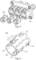
- Fig. 3 shows an exploded view of the connector housing 100 and the shielding sleeve 200.
- the connector housing 100 comprises three terminal cavities 140.
- the shielding sleeves 200 can be provided within a terminal cavity and preferably within a shield cavity. Preferably, each cavity receives one shielding sleeve.
- Fig. 4 shows a detailed view of the shielding sleeve 200.
- the shielding sleeve 200 is preferably formed from a single sheet of metal. After punching or embossing or the like, the shield sleeve is formed cylindrically, in order to form a shielding sleeve.
- the shielding sleeve comprises an outer surface 201 and an inner surface 202.
- the shielding sleeve comprises contact lances 210, wherein the shielding sleeve 200 preferably comprises four contact lances.
- Each contact lance has a spring portion 212 extending radially outward of the shielding sleeve 200 and a contact portion 211 extending radially inward into the shielding sleeve 200.
- the shielding sleeve comprises locking lances 220, wherein the locking lances 220 extend radially outward of the shielding sleeve.
- Figures 5 to 9 show an assembly of the connector system.
- Fig. 5 shows the shielding sleeve 200 in a pre-installed state within the connector housing 100.
- the shielding sleeve 200 is at least partially arranged within a shield cavity 130.
- the connector housing 100 has a terminal cavity 140, formed therein.
- the spring portions 212 extend radially outward of the shielding sleeve 200, wherein the contact portions 211 extend radially inward into the shielding sleeve 200. However, the contact portions 211 do not protrude yet into the terminal cavity 140.
- the contact lances 210 preferably will not be contacted by the terminal and thus, a possible damage of the terminal and/or the contact lance and an unintentional displacement of the shielding sleeve can be avoided.
- the contact lances 210 have a generally s-shape configuration and the spring portion 212 is arranged at one bend of the s-shape and the contact portion 211 is arranged at the other bend of the s-shape.
- the shielding sleeve 200 comprises locking lances 220 that protrude radially outward from the shielding sleeve 200.
- the locking lances 220 engage with the corresponding locking means 121 of the connector housing 100.
- the locking means 121 are an aperture arranged within an outer wall 120 of the connector housing 100.
- the locking lances can be utilized to contact a further shielding element, such as a metallic housing or the like. This allows a continuity shielding of the electrical cable.
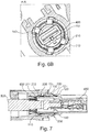
- Fig. 6A shows the shielding sleeve and the connector housing 100 as disclosed in Fig. 5 and a terminal 400 and a shielded cable 500.
- the cable 500 comprises a shield 510 that is over-crimped with a ferrule 600.
- the terminal 400 does not contact the contact lances 210, and in particular not the contact portions 211 of the contact lances 210 of the shielding sleeve 200.
- Fig. 6B shows a cut view along the line A-A of fig. 6A .
- the terminal 400 is guided by a corresponding guiding means that is preferably formed as a corresponding recess 151 in the terminal cavity 140. Further, the contact lances 210 comprising contact portions 211 do not contact the terminal, since the terminal is guided and centered within the terminal cavity 140.
- Fig. 7 shows the electrical connector system of fig. 6A , with the terminal 400 in the installed state.
- the terminal 400 is inserted completely into the terminal cavity 140.
- the ferrule and/or the shield 510 of the cable 500 are arranged opposite to the contact portions 211 or the contact lance 210 of the shielding sleeve 200.
- the wedge element 300 having an actuating means 301 can be arranged within the connector housing 100.
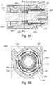
- Figure 8A shows the wedge element 300 in a pre-installed state.
- the wedge element 300 comprises a sealing member 310 that is preferably over-molded over the wedge element 300.
- the sealing member seals the terminal cavity of the housing 100, since it seals the cable against the wedge element and the wedge element 300 against the housing 100.
- the terminal cavity 140 of the housing 100 is sealed.
- the ferrule 600 is crimped on the shield 510 of the shielded cable 500 and does not yet contact the contact portions 211 of the contact lances 210 in the pre-installed state of the wedge element 300.
- the wedge element 300 is guided by guiding means 153 within the connector housing 100.
- the guiding means 153 are formed as guiding rips that extend along the longitudinal direction of the cable 500.
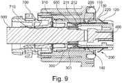
- Fig. 9 shows the electrical connector system 1 in the fully (final) installed state.
- the wedge element 300 surrounds at least parts of the shielding sleeve 200 and bends the at least one contact lance 210 inwardly. Since the contact lance, and in particular the spring portion 212 of the contact lance 210 is bend in inwardly, the contact portion 211 is pressed tightly against the ferrule 600 or alternatively against the shield 510 of the shielded cable. The spring portion 212 thereby applies an increased contact force on the ferrule 600 and/or the shield 510 of the shielded cable 500.
- a cable stop 700 is arranged axially adjacent to the wedge element 300 in the longitudinal direction of the cable 500, so that the wedge element 300 is secured at least axially.
- the cable stop 700 further comprises a strain relieve 710 to protect the cable 500.
Landscapes
- Details Of Connecting Devices For Male And Female Coupling (AREA)
- Connector Housings Or Holding Contact Members (AREA)
Claims (13)
- Elektrisches Verbindersystem (1), das aufweist:ein Verbindergehäuse (100) mit einem darin ausgebildeten Abschirmhohlraum (130); zumindest eine Abschirmhülse (200), die ausgebildet ist, um zumindest teilweise innerhalb des Abschirmhohlraums (130) installiert zu werden, und zumindest ein Klemmelement (300), das ausgebildet ist, um zumindest Teile der Abschirmhülse (200) zu umgeben, wobei die Abschirmhülse (200) zumindest eine Kontaktlanze (210) aufweist, die mit einem Federteil (212) und einem Kontaktteil (211) vorgesehen ist, wobei sich in einem nicht-installierten Zustand der Kontaktteil (211) radial nach innen in die Abschirmhülse (200) erstreckt, wobei sich der Federteil (212) von der Abschirmhülse (200) radial nach außen erstreckt, und wodurch das Klemmelement (300) ausgebildet ist, die zumindest eine Kontaktlanze (210) nach innen zu biegen, wenn das Klemmelement (300) installiert ist, weiter aufweisend ein abgeschirmtes Kabel (500), wobei das abgeschirmte Kabel (500) mit einer Aderendhülse bzw. Ferrule (600) vorgesehen ist, die elektrisch leitend mit der Abschirmung (510) des abgeschirmten Kabels (500) verbunden ist, wobei das abgeschirmte Kabel (500) zumindest teilweise innerhalb des Verbindergehäuses (100) angeordnet ist und wobei die zumindest eine Kontaktlanze (210) nach innen gebogen ist, so dass der Kontaktteil (211) der Kontaktlanze (210) gegen die Abschirmung (510) des abgeschirmten Kabels (500) und/oder die Aderendhülse (600) gedrückt wird, wenn das zumindest eine Klemmelement (300) installiert ist,dadurch gekennzeichnet, dass die zumindest eine Kontaktlanze (210) eine s-förmige Konfiguration hat, wobei der Federteil (212) an einer Biegung der s-Form angeordnet ist und der Kontaktteil (211) an der anderen Biegung der s-Form angeordnet ist.
- Das elektrische Verbindersystem (1) gemäß Anspruch 1, wobei die Kontaktkraft zwischen der Abschirmung (510) des abgeschirmten Kabels (500) und/oder der Aderendhülse (600) und dem Kontaktteil (211) der Kontaktlanze (210) erhöht wird durch Drücken des Kontaktteils (211) gegen die Abschirmung (510) des abgeschirmten Kabels (500) und/oder die Aderendhülse (600), wodurch der elektrisch leitende Kontakt zwischen der Aderendhülse (600) und dem Kontaktteil (211) bis zu einem Vibrationswert von zumindest 392,4 m/s2 Sinus erhalten werden kann.
- Das elektrische Verbindersystem (1) gemäß einem vorhergehenden Anspruch, wobei vor dem installierten Zustand des Klemmelements (300) das zumindest eine Klemmelement (300) verschiebbar auf dem abgeschirmten Kabel (500) angeordnet ist, und wobei in dem installierten Zustand des Klemmelements (300) das zumindest eine Klemmelement (300) zumindest teilweise innerhalb des Verbindergehäuses fest angeordnet ist.
- Das elektrische Verbindersystem (1) gemäß einem vorhergehenden Anspruch, wobei das Klemmelement (300) zumindest ein Betätigungsmittel (301) aufweist, wobei das zumindest eine Betätigungsmittel (301) ausgebildet ist zum Kontaktieren des Federteils (212) der zumindest einen Kontaktlanze (210) und zum Biegen der zumindest einen Kontaktlanze (210) nach innen, wenn das Klemmelement (300) installiert ist.
- Das elektrische Verbindersystem (1) gemäß Anspruch 4, wobei das Betätigungsmittel (301) des Klemmelements (300) rohrförmig ist.
- Das elektrische Verbindersystem (1) gemäß einem vorhergehenden Anspruch, wobei die Abschirmhülse (200) zumindest zwei Kontaktlanzen (210), vorzugsweise zumindest vier Kontaktlanzen (210) und am meisten bevorzugt zumindest sechs Kontaktlanzen (210) aufweist, und wobei das Klemmelement (300) eine entsprechende Anzahl von Betätigungsmitteln (301) aufweist.
- Das elektrische Verbindersystem (1) gemäß einem vorhergehenden Anspruch, wobei
die Abschirmhülse (200) weiter zumindest eine Verriegelungslanze (220) aufweist, die sich von der Abschirmhülse (200) radial nach außen erstreckt, und wobei
das Verbindergehäuse zumindest ein entsprechendes Verriegelungsmittel (121) aufweist, wobei die Verriegelungslanze (220) ausgebildet ist zum Eingriff mit dem Verriegelungsmittel (121), wenn die Abschirmhülse (200) innerhalb des Abschirmhohlraums (130) angeordnet ist. - Das elektrische Verbindersystem (1) gemäß einem vorhergehenden Anspruch, wobei das Verbindergehäuse (100) aufweist einen Anschlusshohlraum (140), der ausgebildet ist zum Aufnehmen zumindest eines elektrischen Anschlusses (400), und wobei sich der Kontaktteil (211) der Kontaktlanze (210) nicht in den Anschlusshohlraum (140) erstreckt, bevor das zumindest eine Klemmelement (300) installiert ist, um zumindest Teile der Abschirmhülse (200) zu umgeben und die zumindest eine Kontaktlanze (210) nach innen zu biegen.
- Das elektrische Verbindersystem (1) gemäß einem vorhergehenden Anspruch, wobei das Verbindergehäuse (100) weiter aufweist:zumindest ein erstes Führungsmittel (151) zum Führen des elektrischen Anschlusses (400) innerhalb des Anschlusshohlraums (140), und weiter aufweistzumindest ein zweites Führungsmittel (152) zum Führen der Abschirmung (510) des abgeschirmten Kabels (500) und/oder der Aderendhülse (600) innerhalb des Anschlusshohlraums (140), und noch weiter aufweist zumindest ein drittes Führungsmittel (153) zum Führen des Klemmelements (300) innerhalb des Verbindergehäuses (100).
- Das elektrische Verbindersystem (1) gemäß einem vorhergehenden Anspruch, das weiter aufweist:zumindest einen Kabelanschlag (700), der eine Zugentlastung (710) aufweist, wobei der Kabelanschlag (700) angrenzend an das zumindest eine Klemmelement (300) in Längsrichtung des Kabels angeordnet ist, um das zumindest eine Klemmelement (300) in Längsrichtung des Kabels zu befestigen.
- Das elektrische Verbindersystem (1) gemäß einem vorhergehenden Anspruch, wobei das Klemmelement (300) mit einem Dichtungselement (310) vorgesehen ist, wobei das Dichtungselement (310) umspritzt ist und an dem Klemmelement (300) angeordnet ist, zumindest zwei Dichtungslippen aufweisend, und wobei das Dichtungselement (310) das Klemmelement gegen das Kabel (500) und gegen das Verbindergehäuse (100) abdichtet, so dass der Anschlusshohlraum (140) abgedichtet ist.
- Ein Verfahren zum Zusammenfügen eines elektrischen Verbindersystems (1), wobei das Verfahren aufweist:Vorsehen eines Verbindergehäuses (100), wobei das Verbindergehäuse (100) einen darin ausgebildeten Abschirmhohlraum (130) aufweist;Vorsehen zumindest einer Abschirmhülse (200) und Installieren der zumindest einen Abschirmhülse (200) zumindest teilweise innerhalb des Abschirmhohlraums (130), wobei die Abschirmhülse (200) zumindest eine Kontaktlanze (210) aufweist, die mit einem Federteil (212) und einem Kontaktteil (211) vorgesehen ist, wobei die zumindest eine Kontaktlanze (210) eine s-förmige Konfiguration hat, wobei der Federteil (212) an einer Biegung der s-Form angeordnet ist und der Kontaktteil (211) an der anderen Biegung der s-Form angeordnet ist, wobei in dem nicht-installierten Zustand sich der Federteil (212) von der Abschirmhülse (200) radial nach außen erstreckt und sich der Kontaktteil (211) radial nach innen in die Abschirmhülse (200) erstreckt; undVorsehen zumindest eines Klemmelements (300) und Installieren des zumindest einen Klemmelements (300) zumindest teilweise innerhalb des Verbindergehäuses (100), so dass das zumindest eine Klemmelement (300) zumindest Teile der Abschirmhülse (200) umgibt und die zumindest eine Kontaktlanze (210) nach innen biegt, wobei das Verfahren weiter aufweist:Vorsehen eines abgeschirmten Kabels (500); undVorsehen einer Aderendhülse (600) an dem abgeschirmten Kabel (500), so dass die Aderendhülse (600) elektrisch leitend mit der Abschirmung (510) des abgeschirmten Kabels (500) verbunden ist; undAnordnen des abgeschirmten Kabels (500) zumindest teilweise innerhalb des Verbindergehäuses (100), wobei die zumindest eine Kontaktlanze (210) nach innen gebogen wird, so dass der Kontaktteil (211) der Kontaktlanze (210) gegen die Abschirmung (510) des abgeschirmten Kabels (500) und/oder die Aderendhülse (600) gedrückt wird, wenn das zumindest eine Klemmelement (300) installiert ist.
- Das Verfahren zum Zusammenfügen eines elektrischen Verbindersystems (1) gemäß Anspruch 12, wobei das Verfahren weiter aufweist:Vorsehen zumindest eines Kabelanschlags (700);Anordnen des Kabelanschlags (700) angrenzend an das zumindest eine Klemmelement (300) in Längsrichtung des Kabels (500), um das zumindest eine Klemmelement (300) in Längsrichtung des Kabels (500) zu befestigen; undFühren des elektrischen Anschlusses (400) innerhalb des Anschlusshohlraums (140) unter Verwendung von ersten Führungsmitteln (151), die in dem Verbindergehäuse (100) vorgesehen sind, so dass der elektrische Anschluss (400) die Abschirmhülse (200) nicht kontaktiert, wenn in dem Anschlusshohlraum (140) des Verbindergehäuses (100) angeordnet, bevor das zumindest eine Klemmelement (300) installiert ist, um zumindest Teile der Abschirmhülse (200) zu umgeben und die zumindest eine Kontaktlanze (210) nach innen zu biegen.
Priority Applications (1)
| Application Number | Priority Date | Filing Date | Title |
|---|---|---|---|
| EP15172407.7A EP3107155B8 (de) | 2015-06-16 | 2015-06-16 | Elektrisches steckverbindersystem mit abschirmungshülse und verfahren dafür |
Applications Claiming Priority (1)
| Application Number | Priority Date | Filing Date | Title |
|---|---|---|---|
| EP15172407.7A EP3107155B8 (de) | 2015-06-16 | 2015-06-16 | Elektrisches steckverbindersystem mit abschirmungshülse und verfahren dafür |
Publications (3)
| Publication Number | Publication Date |
|---|---|
| EP3107155A1 EP3107155A1 (de) | 2016-12-21 |
| EP3107155B1 true EP3107155B1 (de) | 2018-11-28 |
| EP3107155B8 EP3107155B8 (de) | 2019-01-16 |
Family
ID=53433101
Family Applications (1)
| Application Number | Title | Priority Date | Filing Date |
|---|---|---|---|
| EP15172407.7A Active EP3107155B8 (de) | 2015-06-16 | 2015-06-16 | Elektrisches steckverbindersystem mit abschirmungshülse und verfahren dafür |
Country Status (1)
| Country | Link |
|---|---|
| EP (1) | EP3107155B8 (de) |
Families Citing this family (13)
| Publication number | Priority date | Publication date | Assignee | Title |
|---|---|---|---|---|
| CN106785625B (zh) * | 2016-12-30 | 2022-10-11 | 深圳市中车业成实业有限公司 | 一种磁悬浮列车圆形屏蔽连接器系统 |
| DE102017118278A1 (de) * | 2017-08-10 | 2019-02-14 | Ims Connector Systems Gmbh | Federhülse für einen elektrischen Steckverbinder sowie Steckverbinder |
| DE102017222809B4 (de) * | 2017-12-14 | 2019-10-02 | Micro-Epsilon Messtechnik Gmbh & Co. Kg | Elektrischer Steckverbinder und Steckverbindung |
| JP6616815B2 (ja) * | 2017-12-20 | 2019-12-04 | 矢崎総業株式会社 | コネクタ及びコネクタ付き電線 |
| CN108039598A (zh) * | 2018-01-02 | 2018-05-15 | 资阳中车电气科技有限公司 | 一种压接屏蔽线缆的动车组连接器 |
| EP3528348B1 (de) * | 2018-02-16 | 2021-12-08 | Aptiv Technologies Limited | Elektrisches abschirmungselement für einen netzwerkverbinder |
| EP3561967B1 (de) * | 2018-04-25 | 2024-03-20 | Aptiv Technologies Limited | Elektrisches abschirmungselement für einen netzwerkverbinder |
| US10926346B2 (en) | 2018-06-20 | 2021-02-23 | Antaya Technologies Corporation | Resistance soldering system |
| CN109149278A (zh) * | 2018-09-17 | 2019-01-04 | 深圳巴斯巴科技发展有限公司 | 一种圆形连接器的屏蔽接触结构 |
| US10770840B1 (en) * | 2019-06-14 | 2020-09-08 | Aptiv Technologies Limited | Shielded electrical connector assembly |
| EP4038298B1 (de) * | 2019-08-23 | 2025-12-03 | Bimed Teknik Aletler Sanayi ve Ticaret Anonim Sirketi | Kabeldurchführungselement |
| DE102020200976A1 (de) * | 2020-01-28 | 2021-07-29 | Te Connectivity Germany Gmbh | Abschirmfederhülse für Hochstromsteckverbindungen |
| FR3131111B1 (fr) | 2021-12-22 | 2024-11-22 | Aptiv Tech Ltd | Ensemble de connexion blindé, connecteur pour cet ensemble de connexion et procédé de fabrication d’un élément de blindage pour cet ensemble de connexion |
Family Cites Families (6)
| Publication number | Priority date | Publication date | Assignee | Title |
|---|---|---|---|---|
| US4547623A (en) | 1983-10-07 | 1985-10-15 | Automation Industries, Inc. | Cable shield grounding apparatus |
| US5237129A (en) | 1991-06-13 | 1993-08-17 | The United States Of America As Represented By The Secretary Of The Navy | Shield ground adapter for kickpipes and stuffing tubes |
| US7137825B2 (en) * | 2004-03-31 | 2006-11-21 | Tyco Electronics Corporation | Shielded electrical jack connector |
| DE102008018205B4 (de) | 2008-04-10 | 2015-12-24 | Pflitsch Gmbh & Co. Kg | Vorrichtung zur elektromagnetisch abgedichteten Anordnung eines Kabels |
| EP2556565B1 (de) | 2010-04-09 | 2018-10-03 | Delphi International Operations Luxembourg S.à r.l. | Elektromagnetische abschirmungsvorrichtung |
| EP2579396B1 (de) * | 2011-10-04 | 2016-12-21 | Tyco Electronics Nederland B.V. | Abgeschirmte Verschlussanordnung für mindestens einen standardisierten Anschluss an einem Kabel |
-
2015
- 2015-06-16 EP EP15172407.7A patent/EP3107155B8/de active Active
Non-Patent Citations (1)
| Title |
|---|
| None * |
Also Published As
| Publication number | Publication date |
|---|---|
| EP3107155B8 (de) | 2019-01-16 |
| EP3107155A1 (de) | 2016-12-21 |
Similar Documents
| Publication | Publication Date | Title |
|---|---|---|
| EP3107155A1 (de) | Elektrisches steckverbindersystem mit abschirmungshülse | |
| EP2556565B1 (de) | Elektromagnetische abschirmungsvorrichtung | |
| EP2681808B1 (de) | Verbinder mit gehäuse mit abstandshalter mit einem projektionspaar | |
| EP2415128B1 (de) | Koaxialverbinder mit innerer abschirmanordnung und verfahren zum zusammenbau eines solchen | |
| KR102777178B1 (ko) | 커넥터 및 케이블을 포함하는 조립체 | |
| EP2319131B1 (de) | Verbinder | |
| EP1686660B1 (de) | Gegenüber der Umgebung abgedichteter selbstzentrierender Verbinder | |
| US9866006B2 (en) | Device for establishing electrical contact between a shield of an electrical cable and a housing, and a pre-assembled cable | |
| EP2715879B1 (de) | Verbindungsstruktur für geflochtenes abschirmungsteil | |
| US10090623B2 (en) | Enclosure assembly for a connector | |
| EP3783756B1 (de) | Verbinder für kraftfahrzeuganwendungen und verfahren zur montage davon | |
| EP2642605A1 (de) | Verbinder | |
| EP2586102B1 (de) | Elektrischer verbinder und elektrische ausrüstungsanordnung mit einem solchen verbinder | |
| CN115428276B (zh) | 带屏蔽连接的圆形插接连接器 | |
| CN110770977B (zh) | 具有经压入配合的接触元件的插式连接器部件及其制造方法 | |
| US8597065B2 (en) | Sleeve for electrical connectors and method of assembling | |
| KR20210023734A (ko) | 자동차 적용을 위한 커넥터 | |
| US9225082B2 (en) | Device for electrically connecting a cable, in particular a plug-in connector part | |
| US12237626B2 (en) | Wire harness | |
| CN112825399B (zh) | 用于具有保持肩部的压接组件的压接连接件和压接方法 | |
| EP3429033B1 (de) | Steckverbinder-rückwandanordnung | |
| EP3828036B1 (de) | Elektrischer anschlusskasten und verfahren zur herstellung | |
| CN116581611A (zh) | 具有两件式压接外套圈的轴向电缆端子 | |
| EP4311040A1 (de) | Schirmkontaktelement und verfahren zur herstellung eines solchen schirmkontaktelements | |
| EP4054016A1 (de) | Elektrischer verbinder mit zugentlastung und abdichtung |
Legal Events
| Date | Code | Title | Description |
|---|---|---|---|
| PUAI | Public reference made under article 153(3) epc to a published international application that has entered the european phase |
Free format text: ORIGINAL CODE: 0009012 |
|
| STAA | Information on the status of an ep patent application or granted ep patent |
Free format text: STATUS: THE APPLICATION HAS BEEN PUBLISHED |
|
| AK | Designated contracting states |
Kind code of ref document: A1 Designated state(s): AL AT BE BG CH CY CZ DE DK EE ES FI FR GB GR HR HU IE IS IT LI LT LU LV MC MK MT NL NO PL PT RO RS SE SI SK SM TR |
|
| AX | Request for extension of the european patent |
Extension state: BA ME |
|
| STAA | Information on the status of an ep patent application or granted ep patent |
Free format text: STATUS: REQUEST FOR EXAMINATION WAS MADE |
|
| 17P | Request for examination filed |
Effective date: 20170621 |
|
| RBV | Designated contracting states (corrected) |
Designated state(s): AL AT BE BG CH CY CZ DE DK EE ES FI FR GB GR HR HU IE IS IT LI LT LU LV MC MK MT NL NO PL PT RO RS SE SI SK SM TR |
|
| STAA | Information on the status of an ep patent application or granted ep patent |
Free format text: STATUS: EXAMINATION IS IN PROGRESS |
|
| 17Q | First examination report despatched |
Effective date: 20180129 |
|
| GRAP | Despatch of communication of intention to grant a patent |
Free format text: ORIGINAL CODE: EPIDOSNIGR1 |
|
| STAA | Information on the status of an ep patent application or granted ep patent |
Free format text: STATUS: GRANT OF PATENT IS INTENDED |
|
| INTG | Intention to grant announced |
Effective date: 20180625 |
|
| GRAS | Grant fee paid |
Free format text: ORIGINAL CODE: EPIDOSNIGR3 |
|
| GRAA | (expected) grant |
Free format text: ORIGINAL CODE: 0009210 |
|
| STAA | Information on the status of an ep patent application or granted ep patent |
Free format text: STATUS: THE PATENT HAS BEEN GRANTED |
|
| GRAT | Correction requested after decision to grant or after decision to maintain patent in amended form |
Free format text: ORIGINAL CODE: EPIDOSNCDEC |
|
| AK | Designated contracting states |
Kind code of ref document: B1 Designated state(s): AL AT BE BG CH CY CZ DE DK EE ES FI FR GB GR HR HU IE IS IT LI LT LU LV MC MK MT NL NO PL PT RO RS SE SI SK SM TR |
|
| REG | Reference to a national code |
Ref country code: CH Ref legal event code: EP |
|
| REG | Reference to a national code |
Ref country code: AT Ref legal event code: REF Ref document number: 1071341 Country of ref document: AT Kind code of ref document: T Effective date: 20181215 |
|
| RAP2 | Party data changed (patent owner data changed or rights of a patent transferred) |
Owner name: APTIV TECHNOLOGIES LIMITED |
|
| REG | Reference to a national code |
Ref country code: DE Ref legal event code: R096 Ref document number: 602015020287 Country of ref document: DE |
|
| REG | Reference to a national code |
Ref country code: IE Ref legal event code: FG4D |
|
| REG | Reference to a national code |
Ref country code: CH Ref legal event code: PK Free format text: BERICHTIGUNG B8 |
|
| REG | Reference to a national code |
Ref country code: NL Ref legal event code: MP Effective date: 20181128 |
|
| REG | Reference to a national code |
Ref country code: LT Ref legal event code: MG4D |
|
| REG | Reference to a national code |
Ref country code: AT Ref legal event code: MK05 Ref document number: 1071341 Country of ref document: AT Kind code of ref document: T Effective date: 20181128 |
|
| PG25 | Lapsed in a contracting state [announced via postgrant information from national office to epo] |
Ref country code: LV Free format text: LAPSE BECAUSE OF FAILURE TO SUBMIT A TRANSLATION OF THE DESCRIPTION OR TO PAY THE FEE WITHIN THE PRESCRIBED TIME-LIMIT Effective date: 20181128 Ref country code: HR Free format text: LAPSE BECAUSE OF FAILURE TO SUBMIT A TRANSLATION OF THE DESCRIPTION OR TO PAY THE FEE WITHIN THE PRESCRIBED TIME-LIMIT Effective date: 20181128 Ref country code: AT Free format text: LAPSE BECAUSE OF FAILURE TO SUBMIT A TRANSLATION OF THE DESCRIPTION OR TO PAY THE FEE WITHIN THE PRESCRIBED TIME-LIMIT Effective date: 20181128 Ref country code: LT Free format text: LAPSE BECAUSE OF FAILURE TO SUBMIT A TRANSLATION OF THE DESCRIPTION OR TO PAY THE FEE WITHIN THE PRESCRIBED TIME-LIMIT Effective date: 20181128 Ref country code: BG Free format text: LAPSE BECAUSE OF FAILURE TO SUBMIT A TRANSLATION OF THE DESCRIPTION OR TO PAY THE FEE WITHIN THE PRESCRIBED TIME-LIMIT Effective date: 20190228 Ref country code: NO Free format text: LAPSE BECAUSE OF FAILURE TO SUBMIT A TRANSLATION OF THE DESCRIPTION OR TO PAY THE FEE WITHIN THE PRESCRIBED TIME-LIMIT Effective date: 20190228 Ref country code: ES Free format text: LAPSE BECAUSE OF FAILURE TO SUBMIT A TRANSLATION OF THE DESCRIPTION OR TO PAY THE FEE WITHIN THE PRESCRIBED TIME-LIMIT Effective date: 20181128 Ref country code: IS Free format text: LAPSE BECAUSE OF FAILURE TO SUBMIT A TRANSLATION OF THE DESCRIPTION OR TO PAY THE FEE WITHIN THE PRESCRIBED TIME-LIMIT Effective date: 20190328 Ref country code: FI Free format text: LAPSE BECAUSE OF FAILURE TO SUBMIT A TRANSLATION OF THE DESCRIPTION OR TO PAY THE FEE WITHIN THE PRESCRIBED TIME-LIMIT Effective date: 20181128 |
|
| PG25 | Lapsed in a contracting state [announced via postgrant information from national office to epo] |
Ref country code: RS Free format text: LAPSE BECAUSE OF FAILURE TO SUBMIT A TRANSLATION OF THE DESCRIPTION OR TO PAY THE FEE WITHIN THE PRESCRIBED TIME-LIMIT Effective date: 20181128 Ref country code: SE Free format text: LAPSE BECAUSE OF FAILURE TO SUBMIT A TRANSLATION OF THE DESCRIPTION OR TO PAY THE FEE WITHIN THE PRESCRIBED TIME-LIMIT Effective date: 20181128 Ref country code: AL Free format text: LAPSE BECAUSE OF FAILURE TO SUBMIT A TRANSLATION OF THE DESCRIPTION OR TO PAY THE FEE WITHIN THE PRESCRIBED TIME-LIMIT Effective date: 20181128 Ref country code: PT Free format text: LAPSE BECAUSE OF FAILURE TO SUBMIT A TRANSLATION OF THE DESCRIPTION OR TO PAY THE FEE WITHIN THE PRESCRIBED TIME-LIMIT Effective date: 20190328 Ref country code: GR Free format text: LAPSE BECAUSE OF FAILURE TO SUBMIT A TRANSLATION OF THE DESCRIPTION OR TO PAY THE FEE WITHIN THE PRESCRIBED TIME-LIMIT Effective date: 20190301 |
|
| PG25 | Lapsed in a contracting state [announced via postgrant information from national office to epo] |
Ref country code: NL Free format text: LAPSE BECAUSE OF FAILURE TO SUBMIT A TRANSLATION OF THE DESCRIPTION OR TO PAY THE FEE WITHIN THE PRESCRIBED TIME-LIMIT Effective date: 20181128 |
|
| PG25 | Lapsed in a contracting state [announced via postgrant information from national office to epo] |
Ref country code: DK Free format text: LAPSE BECAUSE OF FAILURE TO SUBMIT A TRANSLATION OF THE DESCRIPTION OR TO PAY THE FEE WITHIN THE PRESCRIBED TIME-LIMIT Effective date: 20181128 Ref country code: PL Free format text: LAPSE BECAUSE OF FAILURE TO SUBMIT A TRANSLATION OF THE DESCRIPTION OR TO PAY THE FEE WITHIN THE PRESCRIBED TIME-LIMIT Effective date: 20181128 Ref country code: IT Free format text: LAPSE BECAUSE OF FAILURE TO SUBMIT A TRANSLATION OF THE DESCRIPTION OR TO PAY THE FEE WITHIN THE PRESCRIBED TIME-LIMIT Effective date: 20181128 Ref country code: CZ Free format text: LAPSE BECAUSE OF FAILURE TO SUBMIT A TRANSLATION OF THE DESCRIPTION OR TO PAY THE FEE WITHIN THE PRESCRIBED TIME-LIMIT Effective date: 20181128 |
|
| REG | Reference to a national code |
Ref country code: DE Ref legal event code: R097 Ref document number: 602015020287 Country of ref document: DE |
|
| PG25 | Lapsed in a contracting state [announced via postgrant information from national office to epo] |
Ref country code: RO Free format text: LAPSE BECAUSE OF FAILURE TO SUBMIT A TRANSLATION OF THE DESCRIPTION OR TO PAY THE FEE WITHIN THE PRESCRIBED TIME-LIMIT Effective date: 20181128 Ref country code: SK Free format text: LAPSE BECAUSE OF FAILURE TO SUBMIT A TRANSLATION OF THE DESCRIPTION OR TO PAY THE FEE WITHIN THE PRESCRIBED TIME-LIMIT Effective date: 20181128 Ref country code: SM Free format text: LAPSE BECAUSE OF FAILURE TO SUBMIT A TRANSLATION OF THE DESCRIPTION OR TO PAY THE FEE WITHIN THE PRESCRIBED TIME-LIMIT Effective date: 20181128 Ref country code: EE Free format text: LAPSE BECAUSE OF FAILURE TO SUBMIT A TRANSLATION OF THE DESCRIPTION OR TO PAY THE FEE WITHIN THE PRESCRIBED TIME-LIMIT Effective date: 20181128 |
|
| PLBE | No opposition filed within time limit |
Free format text: ORIGINAL CODE: 0009261 |
|
| STAA | Information on the status of an ep patent application or granted ep patent |
Free format text: STATUS: NO OPPOSITION FILED WITHIN TIME LIMIT |
|
| PG25 | Lapsed in a contracting state [announced via postgrant information from national office to epo] |
Ref country code: SI Free format text: LAPSE BECAUSE OF FAILURE TO SUBMIT A TRANSLATION OF THE DESCRIPTION OR TO PAY THE FEE WITHIN THE PRESCRIBED TIME-LIMIT Effective date: 20181128 |
|
| 26N | No opposition filed |
Effective date: 20190829 |
|
| PG25 | Lapsed in a contracting state [announced via postgrant information from national office to epo] |
Ref country code: MC Free format text: LAPSE BECAUSE OF FAILURE TO SUBMIT A TRANSLATION OF THE DESCRIPTION OR TO PAY THE FEE WITHIN THE PRESCRIBED TIME-LIMIT Effective date: 20181128 |
|
| REG | Reference to a national code |
Ref country code: CH Ref legal event code: PL |
|
| REG | Reference to a national code |
Ref country code: BE Ref legal event code: MM Effective date: 20190630 |
|
| PG25 | Lapsed in a contracting state [announced via postgrant information from national office to epo] |
Ref country code: TR Free format text: LAPSE BECAUSE OF FAILURE TO SUBMIT A TRANSLATION OF THE DESCRIPTION OR TO PAY THE FEE WITHIN THE PRESCRIBED TIME-LIMIT Effective date: 20181128 |
|
| PG25 | Lapsed in a contracting state [announced via postgrant information from national office to epo] |
Ref country code: IE Free format text: LAPSE BECAUSE OF NON-PAYMENT OF DUE FEES Effective date: 20190616 |
|
| PG25 | Lapsed in a contracting state [announced via postgrant information from national office to epo] |
Ref country code: LU Free format text: LAPSE BECAUSE OF NON-PAYMENT OF DUE FEES Effective date: 20190616 Ref country code: BE Free format text: LAPSE BECAUSE OF NON-PAYMENT OF DUE FEES Effective date: 20190630 Ref country code: LI Free format text: LAPSE BECAUSE OF NON-PAYMENT OF DUE FEES Effective date: 20190630 Ref country code: CH Free format text: LAPSE BECAUSE OF NON-PAYMENT OF DUE FEES Effective date: 20190630 |
|
| PG25 | Lapsed in a contracting state [announced via postgrant information from national office to epo] |
Ref country code: CY Free format text: LAPSE BECAUSE OF FAILURE TO SUBMIT A TRANSLATION OF THE DESCRIPTION OR TO PAY THE FEE WITHIN THE PRESCRIBED TIME-LIMIT Effective date: 20181128 |
|
| PG25 | Lapsed in a contracting state [announced via postgrant information from national office to epo] |
Ref country code: HU Free format text: LAPSE BECAUSE OF FAILURE TO SUBMIT A TRANSLATION OF THE DESCRIPTION OR TO PAY THE FEE WITHIN THE PRESCRIBED TIME-LIMIT; INVALID AB INITIO Effective date: 20150616 Ref country code: MT Free format text: LAPSE BECAUSE OF FAILURE TO SUBMIT A TRANSLATION OF THE DESCRIPTION OR TO PAY THE FEE WITHIN THE PRESCRIBED TIME-LIMIT Effective date: 20181128 |
|
| PG25 | Lapsed in a contracting state [announced via postgrant information from national office to epo] |
Ref country code: MK Free format text: LAPSE BECAUSE OF FAILURE TO SUBMIT A TRANSLATION OF THE DESCRIPTION OR TO PAY THE FEE WITHIN THE PRESCRIBED TIME-LIMIT Effective date: 20181128 |
|
| P01 | Opt-out of the competence of the unified patent court (upc) registered |
Effective date: 20230425 |
|
| REG | Reference to a national code |
Ref country code: DE Ref legal event code: R081 Ref document number: 602015020287 Country of ref document: DE Owner name: APTIV TECHNOLOGIES AG, CH Free format text: FORMER OWNER: APTIV TECHNOLOGIES LIMITED, ST. MICHAEL, BB |
|
| PGFP | Annual fee paid to national office [announced via postgrant information from national office to epo] |
Ref country code: DE Payment date: 20250519 Year of fee payment: 11 |
|
| PGFP | Annual fee paid to national office [announced via postgrant information from national office to epo] |
Ref country code: GB Payment date: 20250602 Year of fee payment: 11 |
|
| PGFP | Annual fee paid to national office [announced via postgrant information from national office to epo] |
Ref country code: FR Payment date: 20250611 Year of fee payment: 11 |