EP3107178A1 - Dispositif de commande de transfert de puissance - Google Patents
Dispositif de commande de transfert de puissance Download PDFInfo
- Publication number
- EP3107178A1 EP3107178A1 EP15748783.6A EP15748783A EP3107178A1 EP 3107178 A1 EP3107178 A1 EP 3107178A1 EP 15748783 A EP15748783 A EP 15748783A EP 3107178 A1 EP3107178 A1 EP 3107178A1
- Authority
- EP
- European Patent Office
- Prior art keywords
- power
- communication
- transfer control
- charging
- consumption amount
- Prior art date
- Legal status (The legal status is an assumption and is not a legal conclusion. Google has not performed a legal analysis and makes no representation as to the accuracy of the status listed.)
- Granted
Links
Images


Classifications
-
- B—PERFORMING OPERATIONS; TRANSPORTING
- B60—VEHICLES IN GENERAL
- B60L—PROPULSION OF ELECTRICALLY-PROPELLED VEHICLES; SUPPLYING ELECTRIC POWER FOR AUXILIARY EQUIPMENT OF ELECTRICALLY-PROPELLED VEHICLES; ELECTRODYNAMIC BRAKE SYSTEMS FOR VEHICLES IN GENERAL; MAGNETIC SUSPENSION OR LEVITATION FOR VEHICLES; MONITORING OPERATING VARIABLES OF ELECTRICALLY-PROPELLED VEHICLES; ELECTRIC SAFETY DEVICES FOR ELECTRICALLY-PROPELLED VEHICLES
- B60L53/00—Methods of charging batteries, specially adapted for electric vehicles; Charging stations or on-board charging equipment therefor; Exchange of energy storage elements in electric vehicles
- B60L53/60—Monitoring or controlling charging stations
-
- B—PERFORMING OPERATIONS; TRANSPORTING
- B60—VEHICLES IN GENERAL
- B60L—PROPULSION OF ELECTRICALLY-PROPELLED VEHICLES; SUPPLYING ELECTRIC POWER FOR AUXILIARY EQUIPMENT OF ELECTRICALLY-PROPELLED VEHICLES; ELECTRODYNAMIC BRAKE SYSTEMS FOR VEHICLES IN GENERAL; MAGNETIC SUSPENSION OR LEVITATION FOR VEHICLES; MONITORING OPERATING VARIABLES OF ELECTRICALLY-PROPELLED VEHICLES; ELECTRIC SAFETY DEVICES FOR ELECTRICALLY-PROPELLED VEHICLES
- B60L3/00—Electric devices on electrically-propelled vehicles for safety purposes; Monitoring operating variables, e.g. speed, deceleration or energy consumption
-
- B—PERFORMING OPERATIONS; TRANSPORTING
- B60—VEHICLES IN GENERAL
- B60L—PROPULSION OF ELECTRICALLY-PROPELLED VEHICLES; SUPPLYING ELECTRIC POWER FOR AUXILIARY EQUIPMENT OF ELECTRICALLY-PROPELLED VEHICLES; ELECTRODYNAMIC BRAKE SYSTEMS FOR VEHICLES IN GENERAL; MAGNETIC SUSPENSION OR LEVITATION FOR VEHICLES; MONITORING OPERATING VARIABLES OF ELECTRICALLY-PROPELLED VEHICLES; ELECTRIC SAFETY DEVICES FOR ELECTRICALLY-PROPELLED VEHICLES
- B60L50/00—Electric propulsion with power supplied within the vehicle
- B60L50/50—Electric propulsion with power supplied within the vehicle using propulsion power supplied by batteries or fuel cells
- B60L50/60—Electric propulsion with power supplied within the vehicle using propulsion power supplied by batteries or fuel cells using power supplied by batteries
-
- B—PERFORMING OPERATIONS; TRANSPORTING
- B60—VEHICLES IN GENERAL
- B60L—PROPULSION OF ELECTRICALLY-PROPELLED VEHICLES; SUPPLYING ELECTRIC POWER FOR AUXILIARY EQUIPMENT OF ELECTRICALLY-PROPELLED VEHICLES; ELECTRODYNAMIC BRAKE SYSTEMS FOR VEHICLES IN GENERAL; MAGNETIC SUSPENSION OR LEVITATION FOR VEHICLES; MONITORING OPERATING VARIABLES OF ELECTRICALLY-PROPELLED VEHICLES; ELECTRIC SAFETY DEVICES FOR ELECTRICALLY-PROPELLED VEHICLES
- B60L53/00—Methods of charging batteries, specially adapted for electric vehicles; Charging stations or on-board charging equipment therefor; Exchange of energy storage elements in electric vehicles
- B60L53/10—Methods of charging batteries, specially adapted for electric vehicles; Charging stations or on-board charging equipment therefor; Exchange of energy storage elements in electric vehicles characterised by the energy transfer between the charging station and the vehicle
- B60L53/14—Conductive energy transfer
-
- B—PERFORMING OPERATIONS; TRANSPORTING
- B60—VEHICLES IN GENERAL
- B60L—PROPULSION OF ELECTRICALLY-PROPELLED VEHICLES; SUPPLYING ELECTRIC POWER FOR AUXILIARY EQUIPMENT OF ELECTRICALLY-PROPELLED VEHICLES; ELECTRODYNAMIC BRAKE SYSTEMS FOR VEHICLES IN GENERAL; MAGNETIC SUSPENSION OR LEVITATION FOR VEHICLES; MONITORING OPERATING VARIABLES OF ELECTRICALLY-PROPELLED VEHICLES; ELECTRIC SAFETY DEVICES FOR ELECTRICALLY-PROPELLED VEHICLES
- B60L53/00—Methods of charging batteries, specially adapted for electric vehicles; Charging stations or on-board charging equipment therefor; Exchange of energy storage elements in electric vehicles
- B60L53/30—Constructional details of charging stations
-
- B—PERFORMING OPERATIONS; TRANSPORTING
- B60—VEHICLES IN GENERAL
- B60L—PROPULSION OF ELECTRICALLY-PROPELLED VEHICLES; SUPPLYING ELECTRIC POWER FOR AUXILIARY EQUIPMENT OF ELECTRICALLY-PROPELLED VEHICLES; ELECTRODYNAMIC BRAKE SYSTEMS FOR VEHICLES IN GENERAL; MAGNETIC SUSPENSION OR LEVITATION FOR VEHICLES; MONITORING OPERATING VARIABLES OF ELECTRICALLY-PROPELLED VEHICLES; ELECTRIC SAFETY DEVICES FOR ELECTRICALLY-PROPELLED VEHICLES
- B60L53/00—Methods of charging batteries, specially adapted for electric vehicles; Charging stations or on-board charging equipment therefor; Exchange of energy storage elements in electric vehicles
- B60L53/30—Constructional details of charging stations
- B60L53/305—Communication interfaces
-
- B—PERFORMING OPERATIONS; TRANSPORTING
- B60—VEHICLES IN GENERAL
- B60L—PROPULSION OF ELECTRICALLY-PROPELLED VEHICLES; SUPPLYING ELECTRIC POWER FOR AUXILIARY EQUIPMENT OF ELECTRICALLY-PROPELLED VEHICLES; ELECTRODYNAMIC BRAKE SYSTEMS FOR VEHICLES IN GENERAL; MAGNETIC SUSPENSION OR LEVITATION FOR VEHICLES; MONITORING OPERATING VARIABLES OF ELECTRICALLY-PROPELLED VEHICLES; ELECTRIC SAFETY DEVICES FOR ELECTRICALLY-PROPELLED VEHICLES
- B60L53/00—Methods of charging batteries, specially adapted for electric vehicles; Charging stations or on-board charging equipment therefor; Exchange of energy storage elements in electric vehicles
- B60L53/30—Constructional details of charging stations
- B60L53/31—Charging columns specially adapted for electric vehicles
-
- B—PERFORMING OPERATIONS; TRANSPORTING
- B60—VEHICLES IN GENERAL
- B60L—PROPULSION OF ELECTRICALLY-PROPELLED VEHICLES; SUPPLYING ELECTRIC POWER FOR AUXILIARY EQUIPMENT OF ELECTRICALLY-PROPELLED VEHICLES; ELECTRODYNAMIC BRAKE SYSTEMS FOR VEHICLES IN GENERAL; MAGNETIC SUSPENSION OR LEVITATION FOR VEHICLES; MONITORING OPERATING VARIABLES OF ELECTRICALLY-PROPELLED VEHICLES; ELECTRIC SAFETY DEVICES FOR ELECTRICALLY-PROPELLED VEHICLES
- B60L53/00—Methods of charging batteries, specially adapted for electric vehicles; Charging stations or on-board charging equipment therefor; Exchange of energy storage elements in electric vehicles
- B60L53/60—Monitoring or controlling charging stations
- B60L53/66—Data transfer between charging stations and vehicles
-
- B—PERFORMING OPERATIONS; TRANSPORTING
- B60—VEHICLES IN GENERAL
- B60L—PROPULSION OF ELECTRICALLY-PROPELLED VEHICLES; SUPPLYING ELECTRIC POWER FOR AUXILIARY EQUIPMENT OF ELECTRICALLY-PROPELLED VEHICLES; ELECTRODYNAMIC BRAKE SYSTEMS FOR VEHICLES IN GENERAL; MAGNETIC SUSPENSION OR LEVITATION FOR VEHICLES; MONITORING OPERATING VARIABLES OF ELECTRICALLY-PROPELLED VEHICLES; ELECTRIC SAFETY DEVICES FOR ELECTRICALLY-PROPELLED VEHICLES
- B60L58/00—Methods or circuit arrangements for monitoring or controlling batteries or fuel cells, specially adapted for electric vehicles
- B60L58/10—Methods or circuit arrangements for monitoring or controlling batteries or fuel cells, specially adapted for electric vehicles for monitoring or controlling batteries
- B60L58/12—Methods or circuit arrangements for monitoring or controlling batteries or fuel cells, specially adapted for electric vehicles for monitoring or controlling batteries responding to state of charge [SoC]
- B60L58/13—Maintaining the SoC within a determined range
-
- B—PERFORMING OPERATIONS; TRANSPORTING
- B60—VEHICLES IN GENERAL
- B60L—PROPULSION OF ELECTRICALLY-PROPELLED VEHICLES; SUPPLYING ELECTRIC POWER FOR AUXILIARY EQUIPMENT OF ELECTRICALLY-PROPELLED VEHICLES; ELECTRODYNAMIC BRAKE SYSTEMS FOR VEHICLES IN GENERAL; MAGNETIC SUSPENSION OR LEVITATION FOR VEHICLES; MONITORING OPERATING VARIABLES OF ELECTRICALLY-PROPELLED VEHICLES; ELECTRIC SAFETY DEVICES FOR ELECTRICALLY-PROPELLED VEHICLES
- B60L58/00—Methods or circuit arrangements for monitoring or controlling batteries or fuel cells, specially adapted for electric vehicles
- B60L58/10—Methods or circuit arrangements for monitoring or controlling batteries or fuel cells, specially adapted for electric vehicles for monitoring or controlling batteries
- B60L58/12—Methods or circuit arrangements for monitoring or controlling batteries or fuel cells, specially adapted for electric vehicles for monitoring or controlling batteries responding to state of charge [SoC]
- B60L58/14—Preventing excessive discharging
-
- H—ELECTRICITY
- H02—GENERATION; CONVERSION OR DISTRIBUTION OF ELECTRIC POWER
- H02J—ELECTRIC POWER NETWORKS; CIRCUIT ARRANGEMENTS OR SYSTEMS FOR SUPPLYING OR DISTRIBUTING ELECTRIC POWER; SYSTEMS FOR STORING ELECTRIC ENERGY
- H02J7/00—Circuit arrangements for charging or discharging batteries or for supplying loads from batteries
-
- B—PERFORMING OPERATIONS; TRANSPORTING
- B60—VEHICLES IN GENERAL
- B60L—PROPULSION OF ELECTRICALLY-PROPELLED VEHICLES; SUPPLYING ELECTRIC POWER FOR AUXILIARY EQUIPMENT OF ELECTRICALLY-PROPELLED VEHICLES; ELECTRODYNAMIC BRAKE SYSTEMS FOR VEHICLES IN GENERAL; MAGNETIC SUSPENSION OR LEVITATION FOR VEHICLES; MONITORING OPERATING VARIABLES OF ELECTRICALLY-PROPELLED VEHICLES; ELECTRIC SAFETY DEVICES FOR ELECTRICALLY-PROPELLED VEHICLES
- B60L2250/00—Driver interactions
- B60L2250/10—Driver interactions by alarm
-
- B—PERFORMING OPERATIONS; TRANSPORTING
- B60—VEHICLES IN GENERAL
- B60L—PROPULSION OF ELECTRICALLY-PROPELLED VEHICLES; SUPPLYING ELECTRIC POWER FOR AUXILIARY EQUIPMENT OF ELECTRICALLY-PROPELLED VEHICLES; ELECTRODYNAMIC BRAKE SYSTEMS FOR VEHICLES IN GENERAL; MAGNETIC SUSPENSION OR LEVITATION FOR VEHICLES; MONITORING OPERATING VARIABLES OF ELECTRICALLY-PROPELLED VEHICLES; ELECTRIC SAFETY DEVICES FOR ELECTRICALLY-PROPELLED VEHICLES
- B60L2260/00—Operating Modes
- B60L2260/40—Control modes
- B60L2260/50—Control modes by future state prediction
- B60L2260/52—Control modes by future state prediction drive range estimation, e.g. of estimation of available travel distance
-
- B—PERFORMING OPERATIONS; TRANSPORTING
- B60—VEHICLES IN GENERAL
- B60L—PROPULSION OF ELECTRICALLY-PROPELLED VEHICLES; SUPPLYING ELECTRIC POWER FOR AUXILIARY EQUIPMENT OF ELECTRICALLY-PROPELLED VEHICLES; ELECTRODYNAMIC BRAKE SYSTEMS FOR VEHICLES IN GENERAL; MAGNETIC SUSPENSION OR LEVITATION FOR VEHICLES; MONITORING OPERATING VARIABLES OF ELECTRICALLY-PROPELLED VEHICLES; ELECTRIC SAFETY DEVICES FOR ELECTRICALLY-PROPELLED VEHICLES
- B60L53/00—Methods of charging batteries, specially adapted for electric vehicles; Charging stations or on-board charging equipment therefor; Exchange of energy storage elements in electric vehicles
- B60L53/60—Monitoring or controlling charging stations
- B60L53/65—Monitoring or controlling charging stations involving identification of vehicles or their battery types
-
- B—PERFORMING OPERATIONS; TRANSPORTING
- B60—VEHICLES IN GENERAL
- B60Y—INDEXING SCHEME RELATING TO ASPECTS CROSS-CUTTING VEHICLE TECHNOLOGY
- B60Y2200/00—Type of vehicle
- B60Y2200/90—Vehicles comprising electric prime movers
- B60Y2200/91—Electric vehicles
-
- Y—GENERAL TAGGING OF NEW TECHNOLOGICAL DEVELOPMENTS; GENERAL TAGGING OF CROSS-SECTIONAL TECHNOLOGIES SPANNING OVER SEVERAL SECTIONS OF THE IPC; TECHNICAL SUBJECTS COVERED BY FORMER USPC CROSS-REFERENCE ART COLLECTIONS [XRACs] AND DIGESTS
- Y02—TECHNOLOGIES OR APPLICATIONS FOR MITIGATION OR ADAPTATION AGAINST CLIMATE CHANGE
- Y02T—CLIMATE CHANGE MITIGATION TECHNOLOGIES RELATED TO TRANSPORTATION
- Y02T10/00—Road transport of goods or passengers
- Y02T10/60—Other road transportation technologies with climate change mitigation effect
- Y02T10/70—Energy storage systems for electromobility, e.g. batteries
-
- Y—GENERAL TAGGING OF NEW TECHNOLOGICAL DEVELOPMENTS; GENERAL TAGGING OF CROSS-SECTIONAL TECHNOLOGIES SPANNING OVER SEVERAL SECTIONS OF THE IPC; TECHNICAL SUBJECTS COVERED BY FORMER USPC CROSS-REFERENCE ART COLLECTIONS [XRACs] AND DIGESTS
- Y02—TECHNOLOGIES OR APPLICATIONS FOR MITIGATION OR ADAPTATION AGAINST CLIMATE CHANGE
- Y02T—CLIMATE CHANGE MITIGATION TECHNOLOGIES RELATED TO TRANSPORTATION
- Y02T10/00—Road transport of goods or passengers
- Y02T10/60—Other road transportation technologies with climate change mitigation effect
- Y02T10/7072—Electromobility specific charging systems or methods for batteries, ultracapacitors, supercapacitors or double-layer capacitors
-
- Y—GENERAL TAGGING OF NEW TECHNOLOGICAL DEVELOPMENTS; GENERAL TAGGING OF CROSS-SECTIONAL TECHNOLOGIES SPANNING OVER SEVERAL SECTIONS OF THE IPC; TECHNICAL SUBJECTS COVERED BY FORMER USPC CROSS-REFERENCE ART COLLECTIONS [XRACs] AND DIGESTS
- Y02—TECHNOLOGIES OR APPLICATIONS FOR MITIGATION OR ADAPTATION AGAINST CLIMATE CHANGE
- Y02T—CLIMATE CHANGE MITIGATION TECHNOLOGIES RELATED TO TRANSPORTATION
- Y02T10/00—Road transport of goods or passengers
- Y02T10/80—Technologies aiming to reduce greenhouse gasses emissions common to all road transportation technologies
- Y02T10/92—Energy efficient charging or discharging systems for batteries, ultracapacitors, supercapacitors or double-layer capacitors specially adapted for vehicles
-
- Y—GENERAL TAGGING OF NEW TECHNOLOGICAL DEVELOPMENTS; GENERAL TAGGING OF CROSS-SECTIONAL TECHNOLOGIES SPANNING OVER SEVERAL SECTIONS OF THE IPC; TECHNICAL SUBJECTS COVERED BY FORMER USPC CROSS-REFERENCE ART COLLECTIONS [XRACs] AND DIGESTS
- Y02—TECHNOLOGIES OR APPLICATIONS FOR MITIGATION OR ADAPTATION AGAINST CLIMATE CHANGE
- Y02T—CLIMATE CHANGE MITIGATION TECHNOLOGIES RELATED TO TRANSPORTATION
- Y02T90/00—Enabling technologies or technologies with a potential or indirect contribution to GHG emissions mitigation
- Y02T90/10—Technologies relating to charging of electric vehicles
- Y02T90/12—Electric charging stations
-
- Y—GENERAL TAGGING OF NEW TECHNOLOGICAL DEVELOPMENTS; GENERAL TAGGING OF CROSS-SECTIONAL TECHNOLOGIES SPANNING OVER SEVERAL SECTIONS OF THE IPC; TECHNICAL SUBJECTS COVERED BY FORMER USPC CROSS-REFERENCE ART COLLECTIONS [XRACs] AND DIGESTS
- Y02—TECHNOLOGIES OR APPLICATIONS FOR MITIGATION OR ADAPTATION AGAINST CLIMATE CHANGE
- Y02T—CLIMATE CHANGE MITIGATION TECHNOLOGIES RELATED TO TRANSPORTATION
- Y02T90/00—Enabling technologies or technologies with a potential or indirect contribution to GHG emissions mitigation
- Y02T90/10—Technologies relating to charging of electric vehicles
- Y02T90/14—Plug-in electric vehicles
-
- Y—GENERAL TAGGING OF NEW TECHNOLOGICAL DEVELOPMENTS; GENERAL TAGGING OF CROSS-SECTIONAL TECHNOLOGIES SPANNING OVER SEVERAL SECTIONS OF THE IPC; TECHNICAL SUBJECTS COVERED BY FORMER USPC CROSS-REFERENCE ART COLLECTIONS [XRACs] AND DIGESTS
- Y02—TECHNOLOGIES OR APPLICATIONS FOR MITIGATION OR ADAPTATION AGAINST CLIMATE CHANGE
- Y02T—CLIMATE CHANGE MITIGATION TECHNOLOGIES RELATED TO TRANSPORTATION
- Y02T90/00—Enabling technologies or technologies with a potential or indirect contribution to GHG emissions mitigation
- Y02T90/10—Technologies relating to charging of electric vehicles
- Y02T90/16—Information or communication technologies improving the operation of electric vehicles
Definitions
- Patent document 1 discloses a power transfer control device that is applied to a vehicle including an in-vehicle power storage device, which transfers power to and from an external power source, and a communication unit for transferring power.
- the power transfer control device interrupts the charging of an in-vehicle battery from the external power source and instructs an ECU that controls the car air conditioner to perform maximum output operation. This increases the discharging of the in-vehicle battery.
- Patent document 2 describes performing in-band communication that exchanges more information than information included in the CPLT signal by superimposing a high frequency signal, which has a higher frequency than the CPLT signal, on the CPLT signal.
- a standard for in-band communication regulates that communication is to be interrupted in at least one of a vehicle side and an external power source side when a communication abnormality occurs. If a power transfer control device such as that described in patent document 1 increases discharging of the in-vehicle battery when a communication abnormality occurs, the following problems occur. When charging is desired and a communication abnormality occurs, the charging rate of the in-vehicle battery may be excessively decreased. In addition to a device that performs in-band communication, a device that transfers power while communicating with an external power source may consume storage charge of the in-vehicle battery in an unnecessary manner when a communication abnormality occurs.
- a first aspect of the present invention provides a power transfer control device applied to a vehicle including an in-vehicle power storage device that transfers power to and from an external power source and a communication unit that performs communication to transfer the power.
- the power transfer control device includes a transfer control unit that executes control for transferring the power and a reduction processing unit that reduces a power consumption amount of the transfer control unit to be lower than a power consumption amount of when the transfer control unit executes control for transferring the power under a condition in which an abnormality occurs in the communication.
- the above device executes a process for reducing the power consumption amount of the transfer control unit under a condition in which an abnormality occurs in communication.
- the transfer control unit may be inhibited from consuming power in an unnecessary manner when the power is not transferred.
- the reduction processing unit reduces a power consumption amount of the transfer control unit to be lower than a power consumption amount of when the transfer control unit executes control for transferring the power.
- the power transfer control device further includes a determination unit that determines, after an abnormality occurs in the communication, whether or not to execute a process for reducing the power consumption amount with the reduction processing unit when receiving a value of a parameter related to a stored power amount of the in-vehicle power storage device.
- the power consumption amount of the power transfer control unit is increased as compared to when the reduction processing unit executes a process.
- the amount of the storage charge of the in-vehicle power storage device that is consumed by the power transfer control unit is increased as compared to when the reduction processing unit executes a process.
- a lower limit value of the stored power amount is set in the in-vehicle power storage device.
- the lower limit value of the stored power amount may be set based on a minimum travel distance that is desired by the user.
- the above device uses a value of a parameter related to the stored power amount. This appropriately determines whether or not the process for reducing the power consumption amount of the transfer control unit will be executed.
- the above power transfer control device further includes an obtaining unit that obtains information related to a minimum travel distance that is desired by a user.
- the reduction processing unit executes the process for reducing the power consumption amount.
- the determination unit determines to execute the process for reducing the power consumption amount with the reduction processing unit.
- the reduction processing unit does not execute the process for reducing the power consumption amount when the minimum travel distance desired by the user is not satisfied, the stored power amount of the in-vehicle power storage device is further decreased. This may result in the actual travelable distance being shorter than the minimum travel distance.
- the above device executes the process for reducing the power consumption amount under a condition in which the stored power amount is less than or equal to an amount corresponding to the minimum travel distance.
- the transfer control unit may be inhibited from consuming the storage charge of the in-vehicle power storage device. This limits the actual travelable distance from being less than the minimum travel distance.
- the reduction processing unit executes the process for reducing the power consumption amount.
- the determination unit determines to retry a communication process for charging the in-vehicle power storage device from the external power source without executing the process for reducing a power consumption amount with the reduction processing unit.
- the above power transfer control device further includes a notification processing unit that notifies a user of an abnormality of the communication and information related to a stored power amount of the in-vehicle power storage device when an abnormality occurs in the communication.
- the transfer control unit monitors connection of the power transmission line, and the power consumption amount in the mode for monitoring the connection of the power transmission line is less than the power consumption amount in the mode for executing the control for transferring power.
- the control for transferring power is not executed, whether or not the power transmission line has been connected to the power transfer port may be monitored while reducing the power consumption amount.
- the power consumption amount of the communication unit is reduced by the reduction processing unit. This further reduces the power consumption amount.
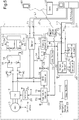
- a vehicle 1 which is an electric vehicle, includes a motor generator 10 that functions as a motor generating driving force of the vehicle 1.
- the motor generator 10 includes a rotation shaft 10a, which is mechanically coupled to a driving wheel.
- the motor generator 10 is connected to an inverter 12, which is a DC-to-AC conversion circuit.
- the inverter 12 includes two input terminals connected to a high voltage battery 16, which is a rechargeable battery, by a system main relay 14 (SMR).
- SMR system main relay 14
- the high voltage battery 16 is an assembled battery in which battery cells are connected in series.
- the high voltage battery 16 is connected to a battery monitor 18, which includes an integrated circuit that monitors the state of the battery cells.
- the high voltage battery 16 is connected to a charger 30 by the SMR 14.
- the charger 30 is a power conversion circuit that charges the high voltage battery 16 from an external power source 50 through terminals T1, T2 of the vehicle.
- a charging control ECU 32 is an electronic control unit that operates the charger 30.
- the charging control ECU 32 controls the charging of the high voltage battery 16 from the external power source 50 based on a request of the user received from an input portion 33 or the like.
- the charging control ECU 32 monitors whether or not the charging gun is connected to charging lines L1, L2.
- a sleep mode in which the power consumption amount is small is switched to a wake-up mode in which the power consumption amount is large. This is because the power consumption amount needed to operate the charger 30 is greater than the power consumption amount needed to monitor the connection of the charging lines L1, L2.
- the process for charging from the external power source 50 is executed when the charging lines L1, L2 are connected to the terminals T1, T2, and communication lines L3, L4 are connected to terminals T3, T4.
- the external power source 50 transmits a control pilot signal (CPLT signal) to the vehicle 1 through the communication lines L3, L4.
- CPLT signal control pilot signal
- the bidirectional communication between the vehicle 1 and the external power source 50, that is, in-band communication, is performed by superimposing a high frequency signal, which has a higher frequency than the CPLT signal, on the CPLT signal through the communication lines L3, L4.
- the in-band communication is performed by a charging communication ECU 40.
- the charging communication ECU 40 includes a voltage monitoring circuit 42, an in-band communication circuit 44, and a controller 46.
- the voltage monitoring circuit 42 detects the potential difference of the communication line L3 relative to the communication line L4, which indicates the reference potential, that is, the voltage of the communication line L3.
- the in-band communication circuit 44 superimposes a high frequency signal on a CPLT signal that transfers through the communication line L3 to perform the in-band communication.
- the controller 46 operates the in-band communication circuit 44 and performs LAN communication with the charging control ECU 32 through a communication line LAN.
- the charging control ECU 32 executes the process for decreasing the voltage of the communication line L3 when the logic of the CPLT signal is "H.”
- the charging control ECU 32 also opens and closes a power relay 34 that connects the accessory battery 26 and the charging communication ECU 40.
- the power supply indicated by a circle is connected to the accessory battery 26 by the power relay 34.
- the charging control ECU 32 is connected to the accessory battery 26 but not by the power relay 34.
- the power supply indicated by a square is connected to the accessory battery 26 but not by the power relay 34.
- the power supply indicated by an inverted triangle is connected to the accessory batter 26 by an electric line that differs from those of the power supplies indicated by a circle and a square.
- the vehicle 1 includes a communication device 47 that is capable of performing wireless communication with an external device using a telephone line or the like.
- the communication device 47 may communicate with the charging control ECU 32 or the like using the communication line LAN.
- the external power source 50 may communicate with a center 52.
- the center 52 obtains information of electricity price that varies in accordance with time or season.
- the center 52 may communicate with the communication device 47 and a portable device 60 carried by the user.
- the portable device 60 is a general multifunctional phone or the like. When the portable device 60 is a general multifunctional phone, a charging communication application program is installed on the portable device 60 so that the portable device 60 is used for the communication for charging the high voltage battery 16.
- the charging control ECU 32 first activates the power relay 34 and activates the power control computer 22 through the communication line LAN.
- the power control computer 22 is normally in the sleep mode.
- the power control computer 22 is regularly switched to the wake-up mode to activate the power switch 18a and monitors the state of the high voltage battery 16. The execution of this process is not triggered when the charging gun is connected to the terminals T1, T2.
- the charging control ECU 32 switches the power control computer 22 to the wake-up mode using the LAN.
- the process for charging the high voltage battery 16 is executed (S10).
- the SMR 14 is closed, and the electric line is connected between the charger 30 and the high voltage battery 16. Additionally, when the power switch 18a is closed, the monitoring unit 18b is activated. The monitoring unit 18b executes the process for monitoring the state of each battery cell included in the high voltage battery 16. At this time, the power consumption amount of the charging control ECU 32 and the power control computer 22 increases, and the charging communication ECU 40 starts to consume power. This decreases the stored power amount of the accessory battery 26. Thus, the power control computer 22 drives the DC-DC converter 24 and executes the process for charging the accessory battery 26 with the storage charge of the high voltage battery 16.
- the charging control ECU 32 executes a user setting reception process that inquires desire of the user about the charging process (S12). As shown in Fig. 3 , in the user setting reception process, the charging control ECU 32 obtains a desired travel distance, a minimum travel distance, charging completion time, and retrying time (S50). Such information is input by the user from the input portion 33.
- the desired travel distance refers to the travelable distance of the vehicle 1 that is desired by the user.
- the minimum travel distance refers to the lower limit value of the travel distance desired by the user.
- the charging completion time refers to the time when the user desires the charging to be completed.
- the retrying time refers to the retrying time desired by the user when an abnormality occurs in in-band communication.
- the charging control ECU 32 sets a target value (target SOC) of the state of charge (SOC) of the high voltage battery 16 based on the desired travel distance (S52). This process is executed based on information related to a travel distance per unit charge amount and the full charge amount of the high voltage battery 16. More specifically, the target SOC is set based on the desired travel distance and the information related to the travel distance per unit charge amount by calculating a charge amount that allows for the traveling of the desired travel distance and subtracting the charge amount from the full charge amount.
- target SOC target SOC of the state of charge (SOC) of the high voltage battery 16 based on the desired travel distance (S52). This process is executed based on information related to a travel distance per unit charge amount and the full charge amount of the high voltage battery 16. More specifically, the target SOC is set based on the desired travel distance and the information related to the travel distance per unit charge amount by calculating a charge amount that allows for the traveling of the desired travel distance and subtracting the charge amount from the full charge amount.
- the charging control ECU 32 determines whether or not the charging has been completed (S20).
- the charging completion refers to the SOC of the high voltage battery reaching the target SOC, which is set in the process of step S52 shown in Fig. 3 .
- the charging control ECU 32 deactivates the power relay 34 and switches to the sleep mode (S26).
- the charging control ECU 32 instructs the power control computer 22 to switch to the sleep mode.
- the power control computer 22 deactivates the SMR 14 and the power switch 18a and then switches itself to the sleep mode. If the charger 30 is already operated and the process for charging the high voltage battery 16 from the external power source 50 is being executed when shifting to this process, the charging process is also terminated.
- the charging control ECU 32 When the set time has elapsed (S18:YES), the charging control ECU 32 outputs the travelable distance based on the present SOC of the high voltage battery 16 and the time elapsed in the charging process to the external power source 50 to notify the user (S28). At this time, the communication device 47 transmits the travelable distance and the elapsed time to the center 52. The center 52 transmits the travelable distance and the elapsed time to the portable device 60. The charging control ECU 32 calculates the travelable distance based on the SOC of the high voltage battery 16, the full charge amount of the high voltage battery 16, and the travel distance per unit charge amount.
- the charging control ECU 32 executes the process for changing the setting of the process of step S12 (S32) and returns to the process of step S16. More specifically, when change is made by the charging completion time, affirmative determination is not made in step S18 at the present time. Thus, the charging control ECU 32 returns to the process of step S16 and continues the charging process. Also, when the charging has not been completed (S20:NO), the charging control ECU 32 returns to step S16.
- the charging control ECU 32 determines whether or not a retrying instruction has been received from the user (S36). This process determines whether or not the user notifies the retrying of the communication from the portable device 60 in response to the notification of the process of step S34.
- the charging control ECU 32 terminates the charging sequence (S37) and returns to the process of step S14 to restart the in-band communication from the beginning. This process is executed in accordance with the standard, that is, when an abnormality occurs in in-band communication, the in-band communication is restarted from the beginning.
- the charging control ECU 32 determines whether or not the travelable distance is less than or equal to the set value A (S40). This process determines whether or not the SOC of the high voltage battery 16 is excessively decreased when the abnormality remains and the in-band communication cannot be performed in spite of the communication retrying.
- the storage charge of the vehicle 1 is consumed in an unnecessary manner as follows. Since the power switch 18a is closed, the monitoring unit 18b continues the monitoring process. Thus, the monitoring unit 18b consumes the storage charge of the high voltage battery 16 in an unnecessary manner. Additionally, the power control computer 22 and the charging control ECU 32 are in the wake-up mode.
- the power control computer 22 drives the DC-DC converter 24 and charges the accessory battery 26 with the storage charge of the high voltage battery 16.
- the power control computer 22, the charging control ECU 32, and the charging communication ECU 40 consume the storage charge of the high voltage battery 16.
- the charging control ECU 32 proceeds to step S26. More specifically, when the travelable distance is less than the minimum desired distance set by the user, the charging control ECU 32 terminates the charging process to avoid further decreases of the SOC of the high voltage battery 16, which will be caused by the continuation of the charging process.
- the first embodiment has the advantages described below.
- the charging control ECU 32 determines whether or not the SOC is less than or equal to a value obtained by adding a margin amount ⁇ to a lower limit value SOCth (S60). This process determines whether or not the SOC is decreased to a level that decreases the reliability of the high voltage battery 16 when the storage charge of the high voltage battery 16 is further consumed.
- the lower limit value SOCth refers to a lower limit value that maintains the reliability of the high voltage battery 16.
- the margin amount ⁇ is set so that the SOC of the high voltage battery 16 is not decreased to be lower than the lower limit value SOCth when negative determination is made in step S60 and the retrying process is continued.
- step S60 the charging control ECU 32 discontinues the charging process and proceeds to the process of step S26 to reduce the power consumption amount of the vehicle 1.
- step S60 the charging control ECU 32 determines whether or not the travelable distance based on the SOC of the high voltage battery 16 is less than or equal to the desired travel distance (S62). This process determines whether or not the SOC of the high voltage battery 16 satisfies the request of the user.
- S62:YES the charging control ECU 32 proceeds to step S37.
- the charging control ECU 32 terminates the charging process and proceeds to step S26.
- FIG. 5 A third embodiment of the present invention will now be described with reference to Fig. 5 .
- the description of the third embodiment will focus on the differences from the first embodiment.
- Fig. 5 the same reference characters are given to those components that are the same as the corresponding components shown in Fig. 1 .
- step S26 the charging control ECU 32 switches itself to the sleep mode. Instead, in the third embodiment, the power supply is interrupted by opening the power relay 70. Consequently, the charging control ECU 32 is unable to monitor whether or not the charging lines L1, L2 are connected to the terminals T1, T2. However, the power consumption amount of the charging control ECU 32 may be further reduced.
- Devices that are activated during the charging may include, for example, the MGECU 20 in addition to the illustrated embodiments. Consequently, even when the SMR 14 is closed and a smoothing capacitor connected to the input terminal of the inverter 12 is charged, the MGECU 20 may operate the inverter 12 to discharge the smoothing capacitor before the charging control ECU 32 is switched to the sleep mode.
- the smoothing capacitor may be discharged by applying reactive current to the motor generator 10 or applying shortcircuit current to upper and lower arms of the inverter 12.
- the parameter of the stored power amount may be obtained by comparing SOC that conforms to the desire of the user and the actual SOC instead of using the travelable distance.
- the SOC conforming to the desire of the user may be obtained from information of the SOC desired by the user instead of the process of step S40 shown in Fig. 3 .
- the SOC conforming to the desire of the user may be obtained by converting the travelable distance input by the user.
- the stored power amount may be used.
- a vehicle When a vehicle includes an in-vehicle power storage device capable of charging and discharging and a fuel battery, information related to a travel distance may be generated taking into consideration not only the amount of power stored in the power storage device but also the amount of power that the fuel battery is capable of generating.
- a hybrid vehicle includes a device for storing electric energy and a fuel storage that stores fuel combusted in the internal combustion engine, a travelable distance including combustion energy of the fuel may be used as information related to a travel distance.
- the period in which an abnormality occurs in communication is not limited to when an abnormality occurs in communication that is started by connecting the charging gun and the communication lunes L3, L4.
- an abnormality may occur in the in-band communication performed when starting the charging.
- the charging control ECU 32 is switched to the sleep mode.
- the charging control ECU 32 is activated when the predetermined time elapses.
- the charging control ECU 32 closes the power relay 34 and instructs the charging communication ECU 40 to perform in-band communication.
- the probability of the user being near the vehicle 1 is lower than immediately after the charging gun is connected.
- notification to the portable device 60 is particularly advantageous.
- the user is notified of an abnormality by the portable device 60. Instead, the user may be notified by visual information or audial information.
- a device that notifies the user of an abnormality may be an energy control device having the above function and located inside a house.
- the power supply of the charging control ECU 32 is switched from an interruption state to a supply state by the power control computer 22.
- the charging control ECU 32 may be powered on, for example, when the user operates an operation member.
- the function that monitors the high voltage battery 16 and the function that outputs an instruction to the MGECU 20 may be included in different hardware devices instead of being included in the single power control computer 22.
- a charging device that charges the high voltage battery 16 from the external power source 50 may include, for example, a portion of the inverter 12, which serves as components of the charging device, other than the dedicated charger 30.
- the charging control ECU 32 and the MGECU 20 may be integrated.
- the charger 30 may be connected between the SMR 14 and the high voltage battery 16 by a relay that opens and closes the electric line or the like. This avoids connection between the inverter 12 and the high voltage battery 16 when charging the high voltage battery 16 from the external power source 50.
- a boost converter may be arranged between the high voltage battery 16 and the inverter 12.
Landscapes
- Engineering & Computer Science (AREA)
- Power Engineering (AREA)
- Transportation (AREA)
- Mechanical Engineering (AREA)
- Life Sciences & Earth Sciences (AREA)
- Sustainable Development (AREA)
- Sustainable Energy (AREA)
- Charge And Discharge Circuits For Batteries Or The Like (AREA)
- Electric Propulsion And Braking For Vehicles (AREA)
Applications Claiming Priority (2)
| Application Number | Priority Date | Filing Date | Title |
|---|---|---|---|
| JP2014024372A JP6112033B2 (ja) | 2014-02-12 | 2014-02-12 | 電力授受制御装置 |
| PCT/JP2015/050258 WO2015122214A1 (fr) | 2014-02-12 | 2015-01-07 | Dispositif de commande de transfert de puissance |
Publications (3)
| Publication Number | Publication Date |
|---|---|
| EP3107178A1 true EP3107178A1 (fr) | 2016-12-21 |
| EP3107178A4 EP3107178A4 (fr) | 2017-05-10 |
| EP3107178B1 EP3107178B1 (fr) | 2018-12-05 |
Family
ID=53799962
Family Applications (1)
| Application Number | Title | Priority Date | Filing Date |
|---|---|---|---|
| EP15748783.6A Active EP3107178B1 (fr) | 2014-02-12 | 2015-01-07 | Dispositif de commande de transfert de puissance |
Country Status (6)
| Country | Link |
|---|---|
| US (1) | US10259328B2 (fr) |
| EP (1) | EP3107178B1 (fr) |
| JP (1) | JP6112033B2 (fr) |
| KR (1) | KR101873666B1 (fr) |
| CN (1) | CN105981255B (fr) |
| WO (1) | WO2015122214A1 (fr) |
Cited By (4)
| Publication number | Priority date | Publication date | Assignee | Title |
|---|---|---|---|---|
| EP3342631A1 (fr) * | 2016-12-30 | 2018-07-04 | Textron, Inc. | Commande d'accès électrique à une batterie au lithium sur un véhicule utilitaire |
| CN109017352A (zh) * | 2018-06-21 | 2018-12-18 | 重庆国翰能源发展有限公司 | 一种充电桩储能结构供电监控方法 |
| EP4262046A1 (fr) * | 2022-03-16 | 2023-10-18 | Toyota Jidosha Kabushiki Kaisha | Véhicule et procédé de commande de communication pour celui-ci |
| CN116901775A (zh) * | 2023-09-14 | 2023-10-20 | 永联科技(常熟)有限公司 | 一种充电枪检测方法及相关设备 |
Families Citing this family (18)
| Publication number | Priority date | Publication date | Assignee | Title |
|---|---|---|---|---|
| JP5942570B2 (ja) | 2011-11-28 | 2016-06-29 | ブラザー工業株式会社 | インクジェット記録装置 |
| JP6361593B2 (ja) | 2015-06-26 | 2018-07-25 | トヨタ自動車株式会社 | 車両および燃料電池システム |
| CN107627867B (zh) * | 2017-01-09 | 2020-12-08 | 上海蔚来汽车有限公司 | 待充电对象充电授权方法、充电设备自动授权方法和系统 |
| DE102017000714A1 (de) * | 2017-01-26 | 2018-07-26 | Borgward Trademark Holdings Gmbh | Verfahren, Batteriemanagementsystem und Fahrzeug für Auflade-Aufwachmodus |
| KR102690900B1 (ko) * | 2017-02-08 | 2024-08-02 | 엘지이노텍 주식회사 | 전기 자동차의 충전을 위한 충전 제어 장치 |
| EP3589513B1 (fr) * | 2017-03-03 | 2022-10-05 | ABB Schweiz AG | Détection de soudage de contacteurs de cc |
| CN107221973A (zh) * | 2017-05-11 | 2017-09-29 | 上海蔚来汽车有限公司 | 待充电对象、充电设备的鉴权方法和系统 |
| KR102603886B1 (ko) * | 2018-02-13 | 2023-11-21 | 엘지이노텍 주식회사 | 전기 자동차의 충전 제어 장치 |
| JP7380272B2 (ja) * | 2020-02-04 | 2023-11-15 | トヨタ自動車株式会社 | 車両 |
| US11241973B2 (en) * | 2020-02-17 | 2022-02-08 | Ford Global Technologies, Llc | Pilot control circuit for charging a vehicle with a charging station |
| JP7276236B2 (ja) * | 2020-04-22 | 2023-05-18 | トヨタ自動車株式会社 | 電源回路の制御装置及び電源回路制御プログラム |
| US20230148678A1 (en) * | 2020-04-22 | 2023-05-18 | Jt International Sa | Electrical System for an Aerosol Generating Device |
| JP7509021B2 (ja) * | 2020-12-14 | 2024-07-02 | トヨタ自動車株式会社 | 車載システム、車載システム制御方法、及び車載システム制御プログラム |
| KR20220167117A (ko) * | 2021-06-11 | 2022-12-20 | 주식회사 엘지에너지솔루션 | 과방전 방지 장치 및 방법 |
| DE102021211841A1 (de) | 2021-10-20 | 2023-04-20 | Robert Bosch Gesellschaft mit beschränkter Haftung | Weckschaltung für ein Fahrzeug, Bordnetz eines Fahrzeugs |
| CN114683849B (zh) * | 2021-10-25 | 2024-03-22 | 北京新能源汽车股份有限公司 | 一种充电桩异常唤醒确定方法、提示方法和装置 |
| CN118679618A (zh) * | 2022-09-08 | 2024-09-20 | 宁德时代新能源科技股份有限公司 | 电池系统的控制方法及控制装置 |
| JP2024126920A (ja) * | 2023-03-08 | 2024-09-20 | トヨタ自動車株式会社 | 充電制御装置および充電制御方法 |
Family Cites Families (18)
| Publication number | Priority date | Publication date | Assignee | Title |
|---|---|---|---|---|
| JP3737067B2 (ja) * | 2002-05-10 | 2006-01-18 | 住友ナコ マテリアル ハンドリング株式会社 | 車両用バッテリ充電装置およびバッテリ充電システム |
| JP2004153967A (ja) | 2002-10-31 | 2004-05-27 | Icom Inc | 充電制御方法 |
| JP2006074868A (ja) | 2004-08-31 | 2006-03-16 | Fuji Heavy Ind Ltd | 電気自動車のバッテリ充電システム |
| JP5065958B2 (ja) * | 2008-03-26 | 2012-11-07 | パナソニック株式会社 | 電池パック |
| JP4969547B2 (ja) * | 2008-10-14 | 2012-07-04 | トヨタ自動車株式会社 | 制御装置及び充電制御方法 |
| JP2010104114A (ja) | 2008-10-22 | 2010-05-06 | Toyota Motor Corp | 車両の制御装置および車両 |
| US8174382B2 (en) | 2008-11-21 | 2012-05-08 | Mahle International Gmbh | Diagnostic system having a wake-up circuit |
| JP5531587B2 (ja) * | 2009-12-02 | 2014-06-25 | 株式会社デンソー | 充電状態報知装置 |
| JP5761756B2 (ja) * | 2010-12-10 | 2015-08-12 | ニチコン株式会社 | 充電制御装置 |
| JP2012147549A (ja) | 2011-01-11 | 2012-08-02 | Denso Corp | 車両用充電予約システム |
| JP5522115B2 (ja) | 2011-04-27 | 2014-06-18 | 株式会社デンソー | 充電制御装置 |
| WO2013008921A1 (fr) * | 2011-07-13 | 2013-01-17 | 住友電気工業株式会社 | Système et dispositif de communication |
| JP5764420B2 (ja) * | 2011-07-22 | 2015-08-19 | 日鉄住金テックスエンジ株式会社 | 電気自動車の充電方法及びその設備 |
| WO2013054387A1 (fr) * | 2011-10-11 | 2013-04-18 | トヨタ自動車株式会社 | Dispositif de régulation de charge pour véhicule et véhicule équipé de celui-ci |
| CN104137451B (zh) * | 2012-02-28 | 2017-10-17 | 住友电气工业株式会社 | 通信系统、通信装置、供电装置、和车辆 |
| JP5720620B2 (ja) | 2012-04-26 | 2015-05-20 | トヨタ自動車株式会社 | 車両 |
| EP2985874B1 (fr) * | 2013-03-29 | 2017-06-14 | Nissan Motor Co., Ltd | Système d'alimentation électrique sans contact |
| KR101849357B1 (ko) * | 2013-10-24 | 2018-04-16 | 한화지상방산 주식회사 | 차량 주행 제어 방법 |
-
2014
- 2014-02-12 JP JP2014024372A patent/JP6112033B2/ja active Active
-
2015
- 2015-01-07 CN CN201580007683.6A patent/CN105981255B/zh active Active
- 2015-01-07 KR KR1020167024486A patent/KR101873666B1/ko active Active
- 2015-01-07 WO PCT/JP2015/050258 patent/WO2015122214A1/fr not_active Ceased
- 2015-01-07 US US15/115,467 patent/US10259328B2/en active Active
- 2015-01-07 EP EP15748783.6A patent/EP3107178B1/fr active Active
Cited By (11)
| Publication number | Priority date | Publication date | Assignee | Title |
|---|---|---|---|---|
| EP3342631A1 (fr) * | 2016-12-30 | 2018-07-04 | Textron, Inc. | Commande d'accès électrique à une batterie au lithium sur un véhicule utilitaire |
| CN108263228A (zh) * | 2016-12-30 | 2018-07-10 | 特克斯特朗创新有限公司 | 控制至多用途车辆上的锂电池的电通路 |
| US10322688B2 (en) | 2016-12-30 | 2019-06-18 | Textron Innovations Inc. | Controlling electrical access to a lithium battery on a utility vehicle |
| US10933755B2 (en) | 2016-12-30 | 2021-03-02 | Textron Innovations Inc. | Controlling electrical access to a lithium battery on a utility vehicle |
| US11325482B2 (en) | 2016-12-30 | 2022-05-10 | Textron Innovations Inc. | Controlling electrical access to a lithium battery on a utility vehicle |
| US11865927B2 (en) | 2016-12-30 | 2024-01-09 | Textron Innovations Inc. | Controlling electrical access to a lithium battery on a utility vehicle |
| US12240340B2 (en) | 2016-12-30 | 2025-03-04 | Textron Innovations Inc. | Controlling electrical access to a lithium battery on a utility vehicle |
| CN109017352A (zh) * | 2018-06-21 | 2018-12-18 | 重庆国翰能源发展有限公司 | 一种充电桩储能结构供电监控方法 |
| EP4262046A1 (fr) * | 2022-03-16 | 2023-10-18 | Toyota Jidosha Kabushiki Kaisha | Véhicule et procédé de commande de communication pour celui-ci |
| CN116901775A (zh) * | 2023-09-14 | 2023-10-20 | 永联科技(常熟)有限公司 | 一种充电枪检测方法及相关设备 |
| CN116901775B (zh) * | 2023-09-14 | 2023-12-15 | 永联科技(常熟)有限公司 | 一种充电枪检测方法及相关设备 |
Also Published As
| Publication number | Publication date |
|---|---|
| US20170182893A1 (en) | 2017-06-29 |
| EP3107178B1 (fr) | 2018-12-05 |
| JP6112033B2 (ja) | 2017-04-12 |
| EP3107178A4 (fr) | 2017-05-10 |
| KR101873666B1 (ko) | 2018-07-02 |
| CN105981255B (zh) | 2018-12-21 |
| WO2015122214A1 (fr) | 2015-08-20 |
| US10259328B2 (en) | 2019-04-16 |
| KR20160119167A (ko) | 2016-10-12 |
| CN105981255A (zh) | 2016-09-28 |
| JP2015154529A (ja) | 2015-08-24 |
Similar Documents
| Publication | Publication Date | Title |
|---|---|---|
| EP3107178B1 (fr) | Dispositif de commande de transfert de puissance | |
| CN114889473B (zh) | 电动汽车直流升压充电控制系统、控制方法及车辆 | |
| US9007001B2 (en) | Power supply system and vehicle equipped with power supply system | |
| US9618954B2 (en) | Vehicle charging system and vehicle charging method with first and second charging operations | |
| CN114889456B (zh) | 一种插电式混合汽车v2v直流充电系统及控制方法 | |
| JP6221836B2 (ja) | 車両用電力管理装置 | |
| CN103879399B (zh) | 混合动力车辆的行驶模式切换控制器 | |
| US9136727B2 (en) | Battery charging control device | |
| US20130020863A1 (en) | Power supply system and vehicle equipped with power supply system | |
| US20150352967A1 (en) | Method and aparatus for controller wakeup | |
| CN103490485A (zh) | 应用智能电网的电动汽车双向供电装置及利用该供电装置的双向供电方法 | |
| CN115742853B (zh) | 用于实现电动汽车充放电功能的方法和装置 | |
| CN103441558A (zh) | 充电控制方法、电动汽车车载终端及充电控制系统 | |
| CN111231768B (zh) | 一种电池管理系统、管理方法以及电动车 | |
| JP2018023243A (ja) | 電動車両 | |
| JP2022033951A (ja) | 充放電装置、充放電システムおよび充放電制御方法 | |
| CN115431769A (zh) | 一种电动商用车及其低压供电系统 | |
| JP2011125185A (ja) | 車両の制御装置 | |
| JP2015139325A (ja) | 電力供給制御装置 | |
| CN116513349A (zh) | 一种双电池系统及电动车 | |
| CN113910932A (zh) | 一种车载电源总成及其控制方法 | |
| WO2022270278A1 (fr) | Dispositif et programme de commande de charge | |
| WO2024114889A1 (fr) | Système d'alimentation électrique de véhicule, véhicule électrique et procédé de démarrage |
Legal Events
| Date | Code | Title | Description |
|---|---|---|---|
| PUAI | Public reference made under article 153(3) epc to a published international application that has entered the european phase |
Free format text: ORIGINAL CODE: 0009012 |
|
| STAA | Information on the status of an ep patent application or granted ep patent |
Free format text: STATUS: REQUEST FOR EXAMINATION WAS MADE |
|
| 17P | Request for examination filed |
Effective date: 20160711 |
|
| AK | Designated contracting states |
Kind code of ref document: A1 Designated state(s): AL AT BE BG CH CY CZ DE DK EE ES FI FR GB GR HR HU IE IS IT LI LT LU LV MC MK MT NL NO PL PT RO RS SE SI SK SM TR |
|
| AX | Request for extension of the european patent |
Extension state: BA ME |
|
| RIC1 | Information provided on ipc code assigned before grant |
Ipc: H02J 7/00 20060101AFI20161219BHEP Ipc: B60L 11/18 20060101ALI20161219BHEP Ipc: B60L 3/00 20060101ALI20161219BHEP |
|
| A4 | Supplementary search report drawn up and despatched |
Effective date: 20170406 |
|
| RIC1 | Information provided on ipc code assigned before grant |
Ipc: B60L 11/18 20060101ALI20170401BHEP Ipc: H02J 7/00 20060101AFI20170401BHEP Ipc: B60L 3/00 20060101ALI20170401BHEP |
|
| DAX | Request for extension of the european patent (deleted) | ||
| STAA | Information on the status of an ep patent application or granted ep patent |
Free format text: STATUS: EXAMINATION IS IN PROGRESS |
|
| 17Q | First examination report despatched |
Effective date: 20180117 |
|
| GRAP | Despatch of communication of intention to grant a patent |
Free format text: ORIGINAL CODE: EPIDOSNIGR1 |
|
| STAA | Information on the status of an ep patent application or granted ep patent |
Free format text: STATUS: GRANT OF PATENT IS INTENDED |
|
| INTG | Intention to grant announced |
Effective date: 20180629 |
|
| GRAS | Grant fee paid |
Free format text: ORIGINAL CODE: EPIDOSNIGR3 |
|
| GRAA | (expected) grant |
Free format text: ORIGINAL CODE: 0009210 |
|
| STAA | Information on the status of an ep patent application or granted ep patent |
Free format text: STATUS: THE PATENT HAS BEEN GRANTED |
|
| AK | Designated contracting states |
Kind code of ref document: B1 Designated state(s): AL AT BE BG CH CY CZ DE DK EE ES FI FR GB GR HR HU IE IS IT LI LT LU LV MC MK MT NL NO PL PT RO RS SE SI SK SM TR |
|
| REG | Reference to a national code |
Ref country code: GB Ref legal event code: FG4D |
|
| REG | Reference to a national code |
Ref country code: CH Ref legal event code: EP |
|
| REG | Reference to a national code |
Ref country code: AT Ref legal event code: REF Ref document number: 1074265 Country of ref document: AT Kind code of ref document: T Effective date: 20181215 |
|
| REG | Reference to a national code |
Ref country code: IE Ref legal event code: FG4D |
|
| REG | Reference to a national code |
Ref country code: DE Ref legal event code: R096 Ref document number: 602015020941 Country of ref document: DE |
|
| REG | Reference to a national code |
Ref country code: DE Ref legal event code: R084 Ref document number: 602015020941 Country of ref document: DE |
|
| REG | Reference to a national code |
Ref country code: NL Ref legal event code: MP Effective date: 20181205 |
|
| REG | Reference to a national code |
Ref country code: AT Ref legal event code: MK05 Ref document number: 1074265 Country of ref document: AT Kind code of ref document: T Effective date: 20181205 |
|
| REG | Reference to a national code |
Ref country code: LT Ref legal event code: MG4D |
|
| PG25 | Lapsed in a contracting state [announced via postgrant information from national office to epo] |
Ref country code: AT Free format text: LAPSE BECAUSE OF FAILURE TO SUBMIT A TRANSLATION OF THE DESCRIPTION OR TO PAY THE FEE WITHIN THE PRESCRIBED TIME-LIMIT Effective date: 20181205 Ref country code: HR Free format text: LAPSE BECAUSE OF FAILURE TO SUBMIT A TRANSLATION OF THE DESCRIPTION OR TO PAY THE FEE WITHIN THE PRESCRIBED TIME-LIMIT Effective date: 20181205 Ref country code: LV Free format text: LAPSE BECAUSE OF FAILURE TO SUBMIT A TRANSLATION OF THE DESCRIPTION OR TO PAY THE FEE WITHIN THE PRESCRIBED TIME-LIMIT Effective date: 20181205 Ref country code: NO Free format text: LAPSE BECAUSE OF FAILURE TO SUBMIT A TRANSLATION OF THE DESCRIPTION OR TO PAY THE FEE WITHIN THE PRESCRIBED TIME-LIMIT Effective date: 20190305 Ref country code: FI Free format text: LAPSE BECAUSE OF FAILURE TO SUBMIT A TRANSLATION OF THE DESCRIPTION OR TO PAY THE FEE WITHIN THE PRESCRIBED TIME-LIMIT Effective date: 20181205 Ref country code: ES Free format text: LAPSE BECAUSE OF FAILURE TO SUBMIT A TRANSLATION OF THE DESCRIPTION OR TO PAY THE FEE WITHIN THE PRESCRIBED TIME-LIMIT Effective date: 20181205 Ref country code: BG Free format text: LAPSE BECAUSE OF FAILURE TO SUBMIT A TRANSLATION OF THE DESCRIPTION OR TO PAY THE FEE WITHIN THE PRESCRIBED TIME-LIMIT Effective date: 20190305 Ref country code: LT Free format text: LAPSE BECAUSE OF FAILURE TO SUBMIT A TRANSLATION OF THE DESCRIPTION OR TO PAY THE FEE WITHIN THE PRESCRIBED TIME-LIMIT Effective date: 20181205 |
|
| PG25 | Lapsed in a contracting state [announced via postgrant information from national office to epo] |
Ref country code: GR Free format text: LAPSE BECAUSE OF FAILURE TO SUBMIT A TRANSLATION OF THE DESCRIPTION OR TO PAY THE FEE WITHIN THE PRESCRIBED TIME-LIMIT Effective date: 20190306 Ref country code: AL Free format text: LAPSE BECAUSE OF FAILURE TO SUBMIT A TRANSLATION OF THE DESCRIPTION OR TO PAY THE FEE WITHIN THE PRESCRIBED TIME-LIMIT Effective date: 20181205 Ref country code: SE Free format text: LAPSE BECAUSE OF FAILURE TO SUBMIT A TRANSLATION OF THE DESCRIPTION OR TO PAY THE FEE WITHIN THE PRESCRIBED TIME-LIMIT Effective date: 20181205 Ref country code: RS Free format text: LAPSE BECAUSE OF FAILURE TO SUBMIT A TRANSLATION OF THE DESCRIPTION OR TO PAY THE FEE WITHIN THE PRESCRIBED TIME-LIMIT Effective date: 20181205 |
|
| PG25 | Lapsed in a contracting state [announced via postgrant information from national office to epo] |
Ref country code: NL Free format text: LAPSE BECAUSE OF FAILURE TO SUBMIT A TRANSLATION OF THE DESCRIPTION OR TO PAY THE FEE WITHIN THE PRESCRIBED TIME-LIMIT Effective date: 20181205 |
|
| PG25 | Lapsed in a contracting state [announced via postgrant information from national office to epo] |
Ref country code: PL Free format text: LAPSE BECAUSE OF FAILURE TO SUBMIT A TRANSLATION OF THE DESCRIPTION OR TO PAY THE FEE WITHIN THE PRESCRIBED TIME-LIMIT Effective date: 20181205 Ref country code: CZ Free format text: LAPSE BECAUSE OF FAILURE TO SUBMIT A TRANSLATION OF THE DESCRIPTION OR TO PAY THE FEE WITHIN THE PRESCRIBED TIME-LIMIT Effective date: 20181205 Ref country code: PT Free format text: LAPSE BECAUSE OF FAILURE TO SUBMIT A TRANSLATION OF THE DESCRIPTION OR TO PAY THE FEE WITHIN THE PRESCRIBED TIME-LIMIT Effective date: 20190405 Ref country code: IT Free format text: LAPSE BECAUSE OF FAILURE TO SUBMIT A TRANSLATION OF THE DESCRIPTION OR TO PAY THE FEE WITHIN THE PRESCRIBED TIME-LIMIT Effective date: 20181205 |
|
| PG25 | Lapsed in a contracting state [announced via postgrant information from national office to epo] |
Ref country code: RO Free format text: LAPSE BECAUSE OF FAILURE TO SUBMIT A TRANSLATION OF THE DESCRIPTION OR TO PAY THE FEE WITHIN THE PRESCRIBED TIME-LIMIT Effective date: 20181205 Ref country code: EE Free format text: LAPSE BECAUSE OF FAILURE TO SUBMIT A TRANSLATION OF THE DESCRIPTION OR TO PAY THE FEE WITHIN THE PRESCRIBED TIME-LIMIT Effective date: 20181205 Ref country code: SM Free format text: LAPSE BECAUSE OF FAILURE TO SUBMIT A TRANSLATION OF THE DESCRIPTION OR TO PAY THE FEE WITHIN THE PRESCRIBED TIME-LIMIT Effective date: 20181205 Ref country code: IS Free format text: LAPSE BECAUSE OF FAILURE TO SUBMIT A TRANSLATION OF THE DESCRIPTION OR TO PAY THE FEE WITHIN THE PRESCRIBED TIME-LIMIT Effective date: 20190405 Ref country code: SK Free format text: LAPSE BECAUSE OF FAILURE TO SUBMIT A TRANSLATION OF THE DESCRIPTION OR TO PAY THE FEE WITHIN THE PRESCRIBED TIME-LIMIT Effective date: 20181205 |
|
| REG | Reference to a national code |
Ref country code: CH Ref legal event code: PL |
|
| REG | Reference to a national code |
Ref country code: DE Ref legal event code: R097 Ref document number: 602015020941 Country of ref document: DE |
|
| PG25 | Lapsed in a contracting state [announced via postgrant information from national office to epo] |
Ref country code: LU Free format text: LAPSE BECAUSE OF NON-PAYMENT OF DUE FEES Effective date: 20190107 |
|
| PLBE | No opposition filed within time limit |
Free format text: ORIGINAL CODE: 0009261 |
|
| STAA | Information on the status of an ep patent application or granted ep patent |
Free format text: STATUS: NO OPPOSITION FILED WITHIN TIME LIMIT |
|
| REG | Reference to a national code |
Ref country code: BE Ref legal event code: MM Effective date: 20190131 |
|
| REG | Reference to a national code |
Ref country code: IE Ref legal event code: MM4A |
|
| PG25 | Lapsed in a contracting state [announced via postgrant information from national office to epo] |
Ref country code: SI Free format text: LAPSE BECAUSE OF FAILURE TO SUBMIT A TRANSLATION OF THE DESCRIPTION OR TO PAY THE FEE WITHIN THE PRESCRIBED TIME-LIMIT Effective date: 20181205 Ref country code: FR Free format text: LAPSE BECAUSE OF NON-PAYMENT OF DUE FEES Effective date: 20190205 Ref country code: MC Free format text: LAPSE BECAUSE OF FAILURE TO SUBMIT A TRANSLATION OF THE DESCRIPTION OR TO PAY THE FEE WITHIN THE PRESCRIBED TIME-LIMIT Effective date: 20181205 Ref country code: DK Free format text: LAPSE BECAUSE OF FAILURE TO SUBMIT A TRANSLATION OF THE DESCRIPTION OR TO PAY THE FEE WITHIN THE PRESCRIBED TIME-LIMIT Effective date: 20181205 |
|
| 26N | No opposition filed |
Effective date: 20190906 |
|
| GBPC | Gb: european patent ceased through non-payment of renewal fee |
Effective date: 20190305 |
|
| PG25 | Lapsed in a contracting state [announced via postgrant information from national office to epo] |
Ref country code: BE Free format text: LAPSE BECAUSE OF NON-PAYMENT OF DUE FEES Effective date: 20190131 |
|
| PG25 | Lapsed in a contracting state [announced via postgrant information from national office to epo] |
Ref country code: LI Free format text: LAPSE BECAUSE OF NON-PAYMENT OF DUE FEES Effective date: 20190131 Ref country code: CH Free format text: LAPSE BECAUSE OF NON-PAYMENT OF DUE FEES Effective date: 20190131 |
|
| PG25 | Lapsed in a contracting state [announced via postgrant information from national office to epo] |
Ref country code: GB Free format text: LAPSE BECAUSE OF NON-PAYMENT OF DUE FEES Effective date: 20190305 Ref country code: IE Free format text: LAPSE BECAUSE OF NON-PAYMENT OF DUE FEES Effective date: 20190107 |
|
| PG25 | Lapsed in a contracting state [announced via postgrant information from national office to epo] |
Ref country code: TR Free format text: LAPSE BECAUSE OF FAILURE TO SUBMIT A TRANSLATION OF THE DESCRIPTION OR TO PAY THE FEE WITHIN THE PRESCRIBED TIME-LIMIT Effective date: 20181205 |
|
| PG25 | Lapsed in a contracting state [announced via postgrant information from national office to epo] |
Ref country code: MT Free format text: LAPSE BECAUSE OF NON-PAYMENT OF DUE FEES Effective date: 20190107 |
|
| PG25 | Lapsed in a contracting state [announced via postgrant information from national office to epo] |
Ref country code: CY Free format text: LAPSE BECAUSE OF FAILURE TO SUBMIT A TRANSLATION OF THE DESCRIPTION OR TO PAY THE FEE WITHIN THE PRESCRIBED TIME-LIMIT Effective date: 20181205 |
|
| PG25 | Lapsed in a contracting state [announced via postgrant information from national office to epo] |
Ref country code: HU Free format text: LAPSE BECAUSE OF FAILURE TO SUBMIT A TRANSLATION OF THE DESCRIPTION OR TO PAY THE FEE WITHIN THE PRESCRIBED TIME-LIMIT; INVALID AB INITIO Effective date: 20150107 |
|
| PG25 | Lapsed in a contracting state [announced via postgrant information from national office to epo] |
Ref country code: MK Free format text: LAPSE BECAUSE OF FAILURE TO SUBMIT A TRANSLATION OF THE DESCRIPTION OR TO PAY THE FEE WITHIN THE PRESCRIBED TIME-LIMIT Effective date: 20181205 |
|
| P01 | Opt-out of the competence of the unified patent court (upc) registered |
Effective date: 20230427 |
|
| PGFP | Annual fee paid to national office [announced via postgrant information from national office to epo] |
Ref country code: DE Payment date: 20251203 Year of fee payment: 12 |