EP3107202B1 - Transducteur piézoélectrique en porte à faux - Google Patents
Transducteur piézoélectrique en porte à faux Download PDFInfo
- Publication number
- EP3107202B1 EP3107202B1 EP15200411.5A EP15200411A EP3107202B1 EP 3107202 B1 EP3107202 B1 EP 3107202B1 EP 15200411 A EP15200411 A EP 15200411A EP 3107202 B1 EP3107202 B1 EP 3107202B1
- Authority
- EP
- European Patent Office
- Prior art keywords
- axis
- mass
- piezoelectric
- stable configuration
- elastic lamina
- Prior art date
- Legal status (The legal status is an assumption and is not a legal conclusion. Google has not performed a legal analysis and makes no representation as to the accuracy of the status listed.)
- Active
Links
Images


Classifications
-
- H—ELECTRICITY
- H10—SEMICONDUCTOR DEVICES; ELECTRIC SOLID-STATE DEVICES NOT OTHERWISE PROVIDED FOR
- H10N—ELECTRIC SOLID-STATE DEVICES NOT OTHERWISE PROVIDED FOR
- H10N30/00—Piezoelectric or electrostrictive devices
-
- H—ELECTRICITY
- H02—GENERATION; CONVERSION OR DISTRIBUTION OF ELECTRIC POWER
- H02N—ELECTRIC MACHINES NOT OTHERWISE PROVIDED FOR
- H02N2/00—Electric machines in general using piezoelectric effect, electrostriction or magnetostriction
- H02N2/18—Electric machines in general using piezoelectric effect, electrostriction or magnetostriction producing electrical output from mechanical input, e.g. generators
- H02N2/186—Vibration harvesters
-
- H—ELECTRICITY
- H02—GENERATION; CONVERSION OR DISTRIBUTION OF ELECTRIC POWER
- H02N—ELECTRIC MACHINES NOT OTHERWISE PROVIDED FOR
- H02N2/00—Electric machines in general using piezoelectric effect, electrostriction or magnetostriction
- H02N2/18—Electric machines in general using piezoelectric effect, electrostriction or magnetostriction producing electrical output from mechanical input, e.g. generators
- H02N2/181—Circuits; Control arrangements or methods
-
- H—ELECTRICITY
- H10—SEMICONDUCTOR DEVICES; ELECTRIC SOLID-STATE DEVICES NOT OTHERWISE PROVIDED FOR
- H10N—ELECTRIC SOLID-STATE DEVICES NOT OTHERWISE PROVIDED FOR
- H10N30/00—Piezoelectric or electrostrictive devices
- H10N30/01—Manufacture or treatment
- H10N30/03—Assembling devices that include piezoelectric or electrostrictive parts
-
- H—ELECTRICITY
- H10—SEMICONDUCTOR DEVICES; ELECTRIC SOLID-STATE DEVICES NOT OTHERWISE PROVIDED FOR
- H10N—ELECTRIC SOLID-STATE DEVICES NOT OTHERWISE PROVIDED FOR
- H10N30/00—Piezoelectric or electrostrictive devices
- H10N30/30—Piezoelectric or electrostrictive devices with mechanical input and electrical output, e.g. functioning as generators or sensors
- H10N30/304—Beam type
- H10N30/306—Cantilevers
Definitions
- the present invention relates to an asymmetrical cantilever piezoelectric transducer.
- the invention is particularly suited for providing piezoelectric microtransducers that may be used in miniaturized energy-harvesting systems suitable for supplying, amongst other things, electronic components and/or devices such as low-consumption sensors and actuators, frequently used in portable electronic devices such as cellphones, tablets, portable computers (laptops), video cameras, photographic cameras, consoles for videogames, and so forth.
- electronic components and/or devices such as low-consumption sensors and actuators, frequently used in portable electronic devices such as cellphones, tablets, portable computers (laptops), video cameras, photographic cameras, consoles for videogames, and so forth.
- energy-harvesting systems systems for harvesting energy (known as “energy-harvesting systems” or “energy-scavenging systems”) from environmental energy sources have aroused and continue to arouse considerable interest in a wide range of fields of technology.
- energy-harvesting systems are designed to harvest and store energy generated by mechanical sources and to transfer it to a generic load of an electrical type. In this way, the electrical load does not require batteries or other power-supply systems that are frequently cumbersome and present a poor resistance to mechanical stresses and entail maintenance costs for interventions of replacement.
- systems for harvesting environmental energy cover a considerable interest for devices that are in any case provided with battery-supply systems, which, however, present a rather limited autonomy.
- Environmental energy may be harvested from various available sources and converted into electrical energy by purposely provided transducers.
- available energy sources may be mechanical or acoustic vibrations or, more in general, forces or pressures, chemical energy sources, electromagnetic fields, environmental light, thermal energy sources, etc.
- piezoelectric transducers For harvesting and conversion piezoelectric transducers may, amongst other things, be used.
- a common type of piezoelectric transducer uses a microstructure comprising a supporting body connected to which are cantilever elements, defined by plane plates constrained to the supporting body at one end and having regions of piezoelectric material at least on a portion of a face.
- the piezoelectric material produces a charge that may be harvested and stored in a storage element.
- Piezoelectric transducers of this kind are suitable for efficiently converting mechanical actions in a direction perpendicular to the faces of the cantilever elements (in the resting condition) in so-called "out of plane” directions. In these directions, in fact, it is possible to obtain maximum bending of the cantilever elements.
- a piezoelectric transducer is provided as defined in claim 1.
- an energy-harvesting system is designated as a whole by the reference number 1.
- the energy-harvesting system 1 is particularly, but not exclusively, suited to being used for supplying electronic components and/or devices such as low-consumption sensors and actuators, which are of increasingly frequent use in portable electronic devices such as cellphones, tablets, portable computers (laptops), video cameras, photographic cameras, consoles for videogames, etc.
- Electronic components and devices supplied by the energy-harvesting system 1 may be rendered entirely or partially self-sufficient in order to reduce or eliminate absorption of energy from the main supply system (normally a battery), which thus has a greater autonomy, to the advantage of users.
- the main supply system normally a battery
- the energy-harvesting system 1 may be used either as main supply source and as auxiliary supply source for the electronic components and/or devices indicated above.
- the energy-harvesting system 1 may be arranged alongside a conventional power-supply system, for example of the battery type, and enter into operation when the main power-supply system has run down or presents malfunctioning.
- the energy-harvesting system 1 comprises a piezoelectric converter 2, a harvesting interface 3, a storage element 5, a selective-connection device 6 and a voltage regulator 7. Further, an output of the voltage regulator 7 supplies an electrical load 8.
- the piezoelectric converter 2 supplies a harvesting voltage V H in response to energy supplied by an environmental energy source 4 external to the harvesting system 1.
- the piezoelectric converter 2 supplies a harvesting voltage V H in response to mechanical vibrations transmitted from the external environment and will be described in greater detail in what follows.
- the energy stored in the storage element 5 increases as a result of the charging current I CH and determines a storage voltage V ST .
- the selective-connection device 6 selectively connects and disconnects a supply input 3a of the harvesting interface 3 and the storage element 5 on the basis of the response of the piezoelectric converter 2. More precisely, when the harvesting voltage V H exceeds an activation threshold V A , which represents a state in which the piezoelectric converter 2 is active and receives environmental energy from outside, the selective-connection device 6 connects the harvesting interface 3 to the storage element 5 so that the harvesting interface 3 receives the storage voltage V ST present on the storage element 5. The harvesting interface may thus use the harvesting voltage V H for charging the storage element 5.
- the selective-connection device 6 disconnects the harvesting interface 3 from the storage element 5 so that the consumption of energy of the harvesting interface 3 ceases.
- the selective-connection device comprises a switch 10 and a driving stage 11, configured to control the switch 10 on the basis of the comparison between the harvesting voltage V H and the activation threshold V A .
- the voltage regulator 7 receives the storage voltage V ST and supplies a regulated supply voltage V DD to the electrical load 8 according to the requirement.
- the selective supply device 6 enables consumption of the harvesting interface 3 to be substantially reduced to zero in the absence of activity of the piezoelectric converter 2 and thus prevents the energy accumulated on the storage element 5 from being dissipated without an effective need when the harvesting system 1 is not in a condition to receive energy from the environment.
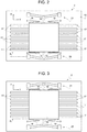
- the piezoelectric converter 2 comprises a microstructure including a supporting body 15, a movable mass 16, and a plurality of cantilever piezoelectric transducers 17.
- the supporting body 15, the movable mass 16, and part of the cantilever piezoelectric transducers 17 are of semiconductor material, for example monocrystalline silicon.
- the supporting body 15 may be a semiconductor monolithic body, or else may be obtained by bonding two or more semiconductor chips, possibly with interposition of bonding layers and/or dielectric layers.
- the movable mass 16 is elastically connected to the supporting body 15 by a system of suspensions 18, configured to enable displacements of the movable mass 16 according to an axis, generally an axis of translation or an axis of rotation.
- the movable mass 16 may translate along an axis X between a first position X 1 ( Figure 2 ) and a second position X 2 ( Figure 3 ).
- the movable mass 16 may comprise, in addition to semiconductor structures, also layers or portions of heavy metals, such as lead or tungsten, in order to improve the energy-harvesting efficiency.
- a first bistable mechanism 20 and a second bistable mechanism 21 are connected to opposite sides of the movable mass 16 with respect to the axis X and are configured to enable movement of the movable mass 16 from the first position X 1 to the second position X 2 , or vice versa from the second position X 2 to the first position X 1 , selectively when a force directed along the axis X and higher than a trigger threshold is applied to the movable mass 16.
- the first bistable mechanism 20 and the second bistable mechanism 21 are coupled to opposite sides of the mass 16 with respect to the second axis X.
- the first bistable mechanism 20 and the second bistable mechanism 21 have respective first stable configurations ( Figure 2 ), when the movable mass 16 is in the first position X 1 , and respective second stable configurations ( Figure 3 ), when the movable mass 16 is in the second position X 2 .
- the first stable configurations and the second stable configurations correspond to respective configurations of minimum of potential energy of the first bistable mechanism 20 and of the second bistable mechanism 21.
- the first bistable mechanism 20 and the second bistable mechanism 21 may deform slightly and then return into the starting stable configuration after the force has been removed.
- the first bistable mechanism 20 and the second bistable mechanism 21 suddenly reach the stable configuration opposite to the starting stable configuration, even if the force is removed before the transition is completed.
- the energy stored by the bistable mechanisms 20, 21 in order for them to undergo deformation beyond a trigger configuration is thus released very rapidly and returned to the movable mass 16.
- the movable mass 16 receives a stress of an impulsive type, which covers a very wide frequency band.
- the trigger threshold may be used as parameter to define with sufficient accuracy the conditions for switching from the first stable configuration to the second stable configuration and vice versa.
- each cantilever piezoelectric transducer 17 comprises a beam 25 of semiconductor material.
- the beam 25 extends in cantilever fashion from a respective anchorage portion 16a of the movable mass 16 in a main direction defined by an axis Y perpendicular to the axis X.
- the beam 25 is formed monolithically from the movable mass 16 and has a constrained end 25a, fixed to the anchorage portion 16a of the movable mass 16, and a free end 25b, opposite to the constrained end 25a.
- the beam 25 has a face 25c parallel to a plane XY defined by the axis X and by the axis Y.
- the face 25c of the beam 25 has a main dimension along the axis Y and a secondary dimension along the axis X.
- a piezoelectric layer 26 is arranged on at least one part of the face 25c of the beam 25.
- the piezoelectric layer 26 may be of PZT (lead zirconate titanate).
- the piezoelectric layer 26 is arranged between a first electrode 27 and a second electrode 28.
- the first electrode 27, in turn, lies on the face 25c of the beam 25 and is electrically insulated therefrom by a dielectric layer 29, made, for example, of silicon oxide.
- the electrodes 27, 28 may be of metal material.
- the face 25c and the stack that includes the first electrode 27, the piezoelectric layer 26, and the second electrode 28 is coated by a passivation layer 30, made, for example, of silicon oxide.
- the beam 25 is shaped so as to bend in response to mechanical stresses transmitted to the movable mass 16, in particular so as to cause a local harvesting voltage between the faces of the piezoelectric layer 26 in contact with the first electrode 27 and the second electrode 28.
- the deformations useful for setting up the local harvesting voltage include bending out of the plane XY defined by the axis X and by the axis Y.
- the beam 25 is shaped so as to bend out of the plane XY also in response to in-plane forces parallel to the axis X.
- a cross-section of the beam 25 perpendicular to its main direction, i.e., perpendicular to the axis Y, is asymmetrical at least along a stretch of the beam 25.
- the cross-section of the beam 25 is asymmetrical with respect to centroidal planes, in particular both to a centroidal plane parallel to the plane XY and to a centroidal plane parallel to a plane YZ, which is defined by the axis Y and by an axis Z perpendicular to the axis X and to the axis Y.
- the beam 25 has a first thickness T1 along a first longitudinal edge 25d and a second thickness T2, smaller than the first thickness T1, along a second longitudinal edge 25e.
- the first thickness T1 is smaller than a width W of the beam 25 (parallel to the axis X).
- the cross-section of the beam 25 perpendicular to its main direction is L-shaped.
- a first longitudinal portion 25f of the beam 25 extends along the first longitudinal edge 25d and has the first thickness T1
- a second longitudinal portion 25g of the beam 25 extends along the second longitudinal edge 25e and has the second thickness T2.
- the transition between the first longitudinal portion 25f and the second longitudinal portion 25g is defined by a wall 25h perpendicular to the axis X.
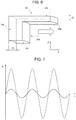
- the beam 25 undergoes deformation principally in response to forces that act in directions parallel to the axis Z (out-of-plane forces, in practice perpendicular to the plane XY). On account of the asymmetrical geometry, however, the beam 25 responds with deformations out of the plane XY also to forces oriented in directions parallel to the axis X. As shown in Figure 6 , a force acting along the axis X on the movable mass 16 produces a first component of deformation (in the plane XY) and, consequently, a first displacement ⁇ X of the free end 25b of the beam 25 with respect to the constrained end 25a.
- the first component of deformation does not contribute in itself to conversion of the mechanical energy into electrical energy because the piezoelectric layer 26 is not loaded for generating a local harvesting voltage between the first electrode 27 and the second electrode 28.
- the force acting along the axis X produces, however, also a second component of perpendicular to the plane XY and a consequent second displacement ⁇ Y of the free end 25b of the beam 25 with respect to the constrained end 25a.
- This type of deformation is basically due to the asymmetry of the beam 25, in particular of the cross-section perpendicular to the axis Y.
- the stresses produced on the cross-section are in turn asymmetrical and lead to deformation out of the plane XY.
- the second component of deformation contributes to generate electrical energy because loading of the piezoelectric layer 26 produces a local harvesting voltage between the first electrode 27 and the second electrode 28.
- the graph of Figure 7 shows with a solid line the oscillations of the free end 25b of the beam 25 along the axis Z as a result of a force pulse parallel to the axis X.
- the oscillations have a smaller amplitude that the ones that derive from force pulses applied directly along the axis Z (dashed line)
- the contribution is, however, not negligible and significantly improves the overall efficiency of the piezoelectric converter 2.
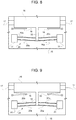
- FIGS 9 and 10 illustrate in greater detail the first bistable mechanism 20. What is described in what follows basically applies also to the second bistable mechanism 21, apart from the details that will be in any case described hereinafter.
- the first bistable mechanism 20 comprises a system of linear elastic elements.
- the first bistable mechanism 20 comprises a first elastic lamina element 20a and a second elastic lamina element 20b, which are defined by respective flexible plates of semiconductor material.
- the elastic lamina elements 20a, 20b may be of other materials, such as glass or metal.
- the first elastic lamina element 20a and the second elastic lamina element 20b have respective ends fixed to a surface of the supporting body 15 by anchorages 31 and for the rest are movable parallel to the plane XY between the first stable configuration and the second stable configuration.
- a bridge element 32 joins central portions of the first elastic lamina element 20a and of the second elastic lamina element 20b to the movable mass 16.
- the first elastic lamina element 20a and the second elastic lamina element 20b have an arched shape, with a geometry selected according to the desired force threshold, and are parallel to one another. More specifically, in the first stable configuration, the first elastic lamina element 20a and the second elastic lamina element 20b define respective first concavities, open on the side facing the movable mass 16. In the second stable configuration, instead, the first elastic lamina element 20a and the second elastic lamina element 20b define respective second concavities, open on the side opposite to the movable mass 16.
- the second bistable mechanism 21 comprises two elastic lamina elements fixed at the ends to the supporting body 15 and at the centre to the movable mass 16 by a bridge element.
- the elastic lamina elements are arched with concavities open on the side opposite to the movable mass 16 in the first stable configuration and on the side facing the movable mass 16 in the second stable configuration.
- transitions of the bistable mechanisms 20, 21 between the respective first stable configurations and the respective second stable configuration require applying a force that has an intensity higher than a trigger threshold and is oriented along the axis X.
- transition of the bistable mechanisms 20, 21 is very fast and causes the force to be transmitted to the movable mass 16 in an impulsive way.
- the cantilever piezoelectric transducers 17, in addition to responding also to in-plane forces directed along the axis X, are excited over a wide frequency band, which also comprises the mechanical resonance frequency of the cantilever piezoelectric transducers 17 themselves.
- the transitions of the bistable mechanisms 20, 21 enable translation to relatively high frequencies of the effects of those mechanical stresses that normally arise at a low frequency, frequently a few Hertz, but constitute an important environmental energy-harvesting source.
- Sources of this type are very useful especially for portable and wearable devices because they frequently derive from movements of the user, such as walking, and are thus always available.
- the frequencies naturally affected by human movement are, however, lower than the natural resonance frequencies of the cantilever piezoelectric transducers 17. In the absence of a frequency-translation mechanism, the response of the cantilever piezoelectric transducers 17 would be attenuated or even negligible. Thanks to the bistable mechanisms 20, 21, instead, the conversion of energy due to forces in the plane parallel to the axis X is carried out also in an efficient way, and a wider range of sources of mechanical stresses may be exploited.
- Figures 10-12 show different embodiments of the invention, in which the cross-section of the beams has different profiles, once again asymmetrical.
- the cross-section of a beam 125 is substantially triangular.
- a piezoelectric layer 126 is located on a plane face 125c parallel to the plane XY.
- a piezoelectric layer 226 is located on a face 225c of a plane beam 225 parallel to the plane XY.
- a face opposite to the face 225c is staircase shaped and has a profile that degrades from a longitudinal edge 225d, where the thickness of the beam 225 is greater, to a second longitudinal edge 225e, where the thickness of the beam 225 is smaller.
- a beam 325 carries a piezoelectric layer 326 on one face 325c.
- An opposite face of the beam 325 has an arched profile degrading from a longitudinal edge 325d, where the thickness of the beam 325 is greater, to a second longitudinal edge 325e, where the thickness of the beam 325 is smaller.
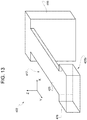
- FIG. 13 illustrates a detail of a piezoelectric converter 402, including a cantilever piezoelectric transducer 417.
- the cantilever piezoelectric transducer 417 comprises a beam 425 that extends in cantilever fashion from a supporting body, for example a movable mass 416 elastically constrained to a substrate (not illustrated).
- the beam 425 In a direction transverse to its own major dimension, the beam 425 has an asymmetrical cross-section, for example L-shaped.
- a weight 426 is fixed to a free end 425b of the beam 425.
- the weight 426 is defined by a mass of semiconductor material of a single piece with the beam 425 and having a thickness equal to the maximum thickness of the beam 425 itself. The design of the weight 426, which may be easily controlled in the production stage, enables precise definition of the resonance frequency of the cantilever piezoelectric transducer 417.
Landscapes
- Engineering & Computer Science (AREA)
- Manufacturing & Machinery (AREA)
- General Electrical Machinery Utilizing Piezoelectricity, Electrostriction Or Magnetostriction (AREA)
Claims (18)
- Transducteur piézoélectrique comprenant :un ancrage (16a) ;une poutre (25 ; 125 ; 225 ; 325 ; 425) en matériau semi-conducteur, s'étendant en porte-à-faux depuis l'ancrage (16a) dans une direction principale parallèle à un premier axe (Y) et ayant une face (25c ; 125c ; 225c ; 325c) parallèle à un premier plan (XY) défini par le premier axe (Y) et par un deuxième axe (X) perpendiculaire au premier axe (Y) ; etune couche piézoélectrique (26) sur la face (25c ; 125c ; 225c ; 325c) de la poutre (25 ; 125 ; 225 ; 325 ; 425) ;une section transversale de la poutre (25 ; 125 ; 225 ; 325 ; 425) perpendiculaire au premier axe (Y) étant asymétrique et formée de sorte que la poutre (25 ; 125 ; 225 ; 325 ; 425) présente des déformations hors du premier plan (XY) en réponse à des forces appliquées à l'ancrage (16) et dirigées selon le deuxième axe (X).
- Transducteur piézoélectrique selon la revendication 1, dans lequel la section transversale de la poutre (25 ; 125 ; 225 ; 325 ; 425) perpendiculaire au premier axe (Y) est asymétrique par rapport à des plans centraux.
- Transducteur piézoélectrique selon la revendication 2, dans lequel la section transversale de la poutre (25 ; 125 ; 225 ; 325 ; 425) perpendiculaire au premier axe (Y) est asymétrique par rapport à un plan central parallèle au premier plan (XY) et à un plan central parallèle à un second plan (YZ), qui est défini par le premier axe (Y) et par un troisième axe (Z) perpendiculaire au premier axe (Y) et au deuxième axe (X).
- Transducteur piézoélectrique selon l'une quelconque des revendications précédentes, dans lequel la poutre (25) a une première épaisseur (T1) le long d'un premier bord longitudinal (25d) et une seconde épaisseur (T2), plus petite que la première épaisseur (T1), le long d'un second bord longitudinal (25e).
- Transducteur piézoélectrique selon la revendication 4, dans lequel une première portion longitudinale (25f) de la poutre (25) s'étend le long du premier bord longitudinal (25d) et a la première épaisseur (T1) ; et une seconde portion longitudinale (25g) de la poutre (25) s'étend le long du second bord longitudinal (25e) et a la seconde épaisseur (T2).
- Transducteur piézoélectrique selon l'une quelconque des revendications précédentes, dans lequel la section transversale de la poutre (25) perpendiculaire au premier axe (Y) est en forme de L.
- Transducteur piézoélectrique selon l'une quelconque des revendications précédentes, dans lequel la couche piézoélectrique (26) est agencée entre une première électrode (27), qui se trouve sur la face (25c) de la poutre (25), et une seconde électrode (28).
- Transducteur piézoélectrique selon l'une quelconque des revendications précédentes, comprenant un poids (426) au niveau d'une extrémité (425b) de la poutre (425).
- Convertisseur piézoélectrique comprenant :un corps de support (15) en matériau semi-conducteur ;une masse (16) de matériau semi-conducteur, mobile par rapport au corps de support (15) ; etune pluralité de transducteurs piézoélectriques (17) selon l'une quelconque des revendications précédentes ancrés sur la masse (16).
- Convertisseur piézoélectrique selon la revendication 9, dans lequel la masse (16) est contrainte élastiquement sur le corps de support (15) et est mobile par rapport au corps de support (15) le long du deuxième axe (X) entre une première position (X1) et une seconde position (X2) .
- Convertisseur piézoélectrique selon la revendication 9 ou la revendication 10, comprenant un dispositif bistable (20, 21) couplé à la masse (16) et configuré pour permettre un déplacement de la masse (16) entre la première position (X1) et la seconde position (X2) en réponse sélectivement à des forces qui sont orientées le long du deuxième axe (X) et ont une intensité supérieure à un seuil de déclenchement.
- Convertisseur piézoélectrique selon la revendication 11, dans lequel le dispositif bistable (20, 21) a une première configuration stable lorsque la masse (16) est dans la première position (X1) et une seconde configuration stable lorsque la masse (16) est dans la seconde position (X2) et est connecté à la masse de sorte que des forces appliquées à la masse (16) et orientées le long du deuxième axe (X) tendent à déformer le dispositif bistable (20, 21) .
- Convertisseur piézoélectrique selon la revendication 12, dans lequel le dispositif bistable (20, 21) comprend un premier mécanisme bistable (20), qui comporte un premier élément de lamelle élastique (20a) et un second élément de lamelle élastique (20b), qui ont des extrémités respectives fixées au corps de support (15), et un élément de pont (32), qui connecte des portions centrales du premier élément de lamelle élastique (20a) et du second élément de lamelle élastique (20b) à la masse (16).
- Convertisseur piézoélectrique selon la revendication 13, dans lequel le premier élément de lamelle élastique (20a) et le second élément de lamelle élastique (20b) sont arqués et parallèles l'un à l'autre dans la première configuration stable et dans la seconde configuration stable et sont mobiles parallèles au premier plan (XY) entre la première configuration stable et la seconde configuration stable.
- Convertisseur piézoélectrique selon la revendication 14, dans lequel le premier élément de lamelle élastique (20a) et le second élément de lamelle élastique (20b) définissent, dans la première configuration stable, des premières concavités respectives ouvertes sur le côté en regard de la masse (16) et, dans la seconde configuration stable, des secondes concavités respectives ouvertes sur le côté opposé à la masse (16).
- Convertisseur selon l'une quelconque des revendications 13 à 15, dans lequel le dispositif bistable (20, 21) comprend un second mécanisme bistable (21), sensiblement identique au premier mécanisme bistable (20), le premier mécanisme bistable (20) et le second mécanisme bistable (21) étant couplés à des côtés opposés de la masse (16) par rapport au deuxième axe (X).
- Convertisseur selon la revendication 16, dans lequel un premier élément de lamelle élastique et un second élément de lamelle élastique du second mécanisme bistable (21) définissent, dans la première configuration stable, des premières concavités respectives ouvertes sur le côté opposé à la masse (16) et, dans la seconde configuration stable, des secondes concavités respectives ouvertes sur le côté en regard de la masse (16).
- Système de récupération d'énergie comprenant un convertisseur piézoélectrique (2) selon l'une quelconque des revendications 9 à 17 et configuré pour récupérer de l'énergie environnementale et pour convertir l'énergie environnementale récupérée en un signal de récupération électrique (VH) ;
un élément de stockage (5), configuré pour stocker de l'énergie électrique dérivant d'une conversion de l'énergie environnementale récupérée par le transducteur piézoélectrique (2) ; et
une interface de récupération (3), couplée au transducteur (2) et configurée pour fournir un signal de charge électrique (ICH) à l'élément de stockage (5) en fonction du signal de récupération électrique (VH).
Applications Claiming Priority (1)
| Application Number | Priority Date | Filing Date | Title |
|---|---|---|---|
| ITUB20151507 | 2015-06-18 |
Publications (2)
| Publication Number | Publication Date |
|---|---|
| EP3107202A1 EP3107202A1 (fr) | 2016-12-21 |
| EP3107202B1 true EP3107202B1 (fr) | 2018-06-13 |
Family
ID=53836789
Family Applications (1)
| Application Number | Title | Priority Date | Filing Date |
|---|---|---|---|
| EP15200411.5A Active EP3107202B1 (fr) | 2015-06-18 | 2015-12-16 | Transducteur piézoélectrique en porte à faux |
Country Status (3)
| Country | Link |
|---|---|
| US (2) | US10135365B2 (fr) |
| EP (1) | EP3107202B1 (fr) |
| CN (2) | CN205595377U (fr) |
Families Citing this family (7)
| Publication number | Priority date | Publication date | Assignee | Title |
|---|---|---|---|---|
| ITTO20130652A1 (it) * | 2013-07-31 | 2015-02-01 | Milano Politecnico | Trasduttore piezoelettrico per un sistema di raccolta dell'energia e metodo per la raccolta di energia mediante un trasduttore piezoelettrico |
| CN205595377U (zh) * | 2015-06-18 | 2016-09-21 | 意法半导体股份有限公司 | 压电换能器、压电转换器和能量收集系统 |
| KR102452948B1 (ko) * | 2017-07-18 | 2022-10-11 | 삼성전자주식회사 | 미소 기계식 공진기 및 이를 포함하는 공진기 시스템 |
| FR3082073B1 (fr) * | 2018-05-29 | 2021-02-19 | Univ Savoie Mont Blanc | Recuperateur d'energie vibratoire |
| IT202000003967A1 (it) | 2020-02-26 | 2021-08-26 | St Microelectronics Srl | Sistema microelettromeccanico e metodo per la fabbricazione dello stesso |
| CN111063790B (zh) * | 2020-03-12 | 2020-07-28 | 共达电声股份有限公司 | 压电换能器、制备压电换能器的方法及电子设备 |
| ES2985836T3 (es) * | 2020-07-06 | 2024-11-07 | Wenjing Wu | Dispositivo de autogeneración |
Family Cites Families (13)
| Publication number | Priority date | Publication date | Assignee | Title |
|---|---|---|---|---|
| EP1684406A1 (fr) * | 2004-06-07 | 2006-07-26 | Matsushita Electric Industrial Co., Ltd. | Actionneur, mécanisme de mouvement précis comprenant l'actionneur, et module à caméra comprenant le mécanisme de mouvement précis |
| WO2007037926A2 (fr) * | 2005-09-23 | 2007-04-05 | Sharp Laboratories Of America, Inc. | Capteur de pixels mems |
| US20080074002A1 (en) * | 2006-09-26 | 2008-03-27 | Shashank Priya | Piezoelectric energy harvester |
| US9048419B2 (en) * | 2007-05-31 | 2015-06-02 | Wayne State University | Piezo devices with air-spaced cantilever |
| US8143765B1 (en) * | 2008-01-30 | 2012-03-27 | TBT Group, Inc. | Self-powering headset, devices and related methods |
| MY162273A (en) * | 2008-09-29 | 2017-05-31 | Mimos Berhad | A device for maximum detection of vibrating energy for harvesting energy |
| US7986076B2 (en) * | 2009-11-02 | 2011-07-26 | Toyota Motor Engineering & Manufacturing North America, Inc, | Energy harvesting device |
| JP5720703B2 (ja) * | 2011-02-04 | 2015-05-20 | 株式会社村田製作所 | 圧電発電装置 |
| KR101774301B1 (ko) * | 2011-12-16 | 2017-09-20 | 한국전자통신연구원 | 에너지 하베스팅 소자 및 그의 제조방법 |
| US9294015B2 (en) * | 2012-05-25 | 2016-03-22 | Electronics And Telecommunications Research Institute | Piezoelectric energy harvesting array and method of manufacturing the same |
| DE112013006824B4 (de) * | 2013-03-13 | 2021-07-22 | Panasonic Corporation | Leistungsgenerator |
| ITTO20130652A1 (it) * | 2013-07-31 | 2015-02-01 | Milano Politecnico | Trasduttore piezoelettrico per un sistema di raccolta dell'energia e metodo per la raccolta di energia mediante un trasduttore piezoelettrico |
| CN205595377U (zh) * | 2015-06-18 | 2016-09-21 | 意法半导体股份有限公司 | 压电换能器、压电转换器和能量收集系统 |
-
2015
- 2015-11-30 CN CN201520977697.8U patent/CN205595377U/zh not_active Withdrawn - After Issue
- 2015-11-30 CN CN201510860679.6A patent/CN106257699B/zh active Active
- 2015-12-16 EP EP15200411.5A patent/EP3107202B1/fr active Active
- 2015-12-28 US US14/980,762 patent/US10135365B2/en active Active
-
2018
- 2018-10-04 US US16/152,076 patent/US11183953B2/en active Active
Non-Patent Citations (1)
| Title |
|---|
| None * |
Also Published As
| Publication number | Publication date |
|---|---|
| EP3107202A1 (fr) | 2016-12-21 |
| US20160373031A1 (en) | 2016-12-22 |
| US20190044458A1 (en) | 2019-02-07 |
| CN106257699A (zh) | 2016-12-28 |
| US11183953B2 (en) | 2021-11-23 |
| CN205595377U (zh) | 2016-09-21 |
| CN106257699B (zh) | 2019-02-22 |
| US10135365B2 (en) | 2018-11-20 |
Similar Documents
| Publication | Publication Date | Title |
|---|---|---|
| EP3107202B1 (fr) | Transducteur piézoélectrique en porte à faux | |
| US10897215B2 (en) | Piezoelectric transducer for an energy-harvesting system | |
| EP1654771B1 (fr) | Appareil de navette a energie de deformation et procede de recueil d'energie de vibration | |
| EP2662971B1 (fr) | Générateur d'énergie piézoélectrique | |
| US9106160B2 (en) | Monolithic energy harvesting system, apparatus, and method | |
| US7520173B2 (en) | Interdigitated electrode for electronic device and electronic device using the same | |
| US7948153B1 (en) | Piezoelectric energy harvester having planform-tapered interdigitated beams | |
| US8093784B2 (en) | Piezoelectric power generating element, and method of generating electric power using the piezoelectric power generating element | |
| JP5386893B2 (ja) | 圧電発電装置 | |
| US9528502B2 (en) | System for conversing thermal energy into electrical energy | |
| EP2566039A1 (fr) | Dispositif de génération de puissance de vibration | |
| JP2008211925A (ja) | 圧電発電装置 | |
| JP2013500695A (ja) | 圧電曲がり素子を変形させる曲げ装置、同曲げ装置を用いて機械的エネルギーを電気エネルギーに変換する圧電エネルギー変換器、及び機械的エネルギーを電気エネルギーに変換する方法 | |
| EP3839602A1 (fr) | Dispositif de miroir microelectromecanique avec actionnement piezoélectrique, ayant une structure améliorée | |
| JP6641134B2 (ja) | 発電デバイスの実装構造及び発電方法 | |
| US10001372B2 (en) | Angular velocity detection device | |
| US8282087B2 (en) | Oscillation decoupling device | |
| JP6699830B2 (ja) | 圧電センサ | |
| JP2010538598A (ja) | 二重ダイヤフラムを備えた圧電性エネルギ変換器 | |
| KR101366066B1 (ko) | 압전 하베스팅 시스템 | |
| US6611081B1 (en) | Vibration actuator with two vibration modes | |
| CN117559840A (zh) | 一种致动器元件和致动器模组 | |
| Rasid et al. | Modelling and experimental validation of piezoelectrically driven micro-lens actuator | |
| JP2020065438A (ja) | 発電デバイスの実装構造及び発電方法 | |
| CN115480388B (zh) | 一种致动器元件和致动器系统 |
Legal Events
| Date | Code | Title | Description |
|---|---|---|---|
| PUAI | Public reference made under article 153(3) epc to a published international application that has entered the european phase |
Free format text: ORIGINAL CODE: 0009012 |
|
| AK | Designated contracting states |
Kind code of ref document: A1 Designated state(s): AL AT BE BG CH CY CZ DE DK EE ES FI FR GB GR HR HU IE IS IT LI LT LU LV MC MK MT NL NO PL PT RO RS SE SI SK SM TR |
|
| AX | Request for extension of the european patent |
Extension state: BA ME |
|
| 17P | Request for examination filed |
Effective date: 20170620 |
|
| RBV | Designated contracting states (corrected) |
Designated state(s): AL AT BE BG CH CY CZ DE DK EE ES FI FR GB GR HR HU IE IS IT LI LT LU LV MC MK MT NL NO PL PT RO RS SE SI SK SM TR |
|
| GRAP | Despatch of communication of intention to grant a patent |
Free format text: ORIGINAL CODE: EPIDOSNIGR1 |
|
| INTG | Intention to grant announced |
Effective date: 20171220 |
|
| INTG | Intention to grant announced |
Effective date: 20180102 |
|
| GRAS | Grant fee paid |
Free format text: ORIGINAL CODE: EPIDOSNIGR3 |
|
| GRAA | (expected) grant |
Free format text: ORIGINAL CODE: 0009210 |
|
| AK | Designated contracting states |
Kind code of ref document: B1 Designated state(s): AL AT BE BG CH CY CZ DE DK EE ES FI FR GB GR HR HU IE IS IT LI LT LU LV MC MK MT NL NO PL PT RO RS SE SI SK SM TR |
|
| REG | Reference to a national code |
Ref country code: GB Ref legal event code: FG4D |
|
| REG | Reference to a national code |
Ref country code: CH Ref legal event code: EP Ref country code: AT Ref legal event code: REF Ref document number: 1009516 Country of ref document: AT Kind code of ref document: T Effective date: 20180615 |
|
| REG | Reference to a national code |
Ref country code: IE Ref legal event code: FG4D |
|
| REG | Reference to a national code |
Ref country code: DE Ref legal event code: R096 Ref document number: 602015012188 Country of ref document: DE |
|
| REG | Reference to a national code |
Ref country code: NL Ref legal event code: MP Effective date: 20180613 |
|
| REG | Reference to a national code |
Ref country code: LT Ref legal event code: MG4D |
|
| PG25 | Lapsed in a contracting state [announced via postgrant information from national office to epo] |
Ref country code: LT Free format text: LAPSE BECAUSE OF FAILURE TO SUBMIT A TRANSLATION OF THE DESCRIPTION OR TO PAY THE FEE WITHIN THE PRESCRIBED TIME-LIMIT Effective date: 20180613 Ref country code: NO Free format text: LAPSE BECAUSE OF FAILURE TO SUBMIT A TRANSLATION OF THE DESCRIPTION OR TO PAY THE FEE WITHIN THE PRESCRIBED TIME-LIMIT Effective date: 20180913 Ref country code: FI Free format text: LAPSE BECAUSE OF FAILURE TO SUBMIT A TRANSLATION OF THE DESCRIPTION OR TO PAY THE FEE WITHIN THE PRESCRIBED TIME-LIMIT Effective date: 20180613 Ref country code: SE Free format text: LAPSE BECAUSE OF FAILURE TO SUBMIT A TRANSLATION OF THE DESCRIPTION OR TO PAY THE FEE WITHIN THE PRESCRIBED TIME-LIMIT Effective date: 20180613 Ref country code: BG Free format text: LAPSE BECAUSE OF FAILURE TO SUBMIT A TRANSLATION OF THE DESCRIPTION OR TO PAY THE FEE WITHIN THE PRESCRIBED TIME-LIMIT Effective date: 20180913 Ref country code: ES Free format text: LAPSE BECAUSE OF FAILURE TO SUBMIT A TRANSLATION OF THE DESCRIPTION OR TO PAY THE FEE WITHIN THE PRESCRIBED TIME-LIMIT Effective date: 20180613 Ref country code: CY Free format text: LAPSE BECAUSE OF FAILURE TO SUBMIT A TRANSLATION OF THE DESCRIPTION OR TO PAY THE FEE WITHIN THE PRESCRIBED TIME-LIMIT Effective date: 20180613 |
|
| PG25 | Lapsed in a contracting state [announced via postgrant information from national office to epo] |
Ref country code: RS Free format text: LAPSE BECAUSE OF FAILURE TO SUBMIT A TRANSLATION OF THE DESCRIPTION OR TO PAY THE FEE WITHIN THE PRESCRIBED TIME-LIMIT Effective date: 20180613 Ref country code: HR Free format text: LAPSE BECAUSE OF FAILURE TO SUBMIT A TRANSLATION OF THE DESCRIPTION OR TO PAY THE FEE WITHIN THE PRESCRIBED TIME-LIMIT Effective date: 20180613 Ref country code: GR Free format text: LAPSE BECAUSE OF FAILURE TO SUBMIT A TRANSLATION OF THE DESCRIPTION OR TO PAY THE FEE WITHIN THE PRESCRIBED TIME-LIMIT Effective date: 20180914 Ref country code: LV Free format text: LAPSE BECAUSE OF FAILURE TO SUBMIT A TRANSLATION OF THE DESCRIPTION OR TO PAY THE FEE WITHIN THE PRESCRIBED TIME-LIMIT Effective date: 20180613 |
|
| REG | Reference to a national code |
Ref country code: AT Ref legal event code: MK05 Ref document number: 1009516 Country of ref document: AT Kind code of ref document: T Effective date: 20180613 |
|
| PG25 | Lapsed in a contracting state [announced via postgrant information from national office to epo] |
Ref country code: NL Free format text: LAPSE BECAUSE OF FAILURE TO SUBMIT A TRANSLATION OF THE DESCRIPTION OR TO PAY THE FEE WITHIN THE PRESCRIBED TIME-LIMIT Effective date: 20180613 |
|
| PG25 | Lapsed in a contracting state [announced via postgrant information from national office to epo] |
Ref country code: EE Free format text: LAPSE BECAUSE OF FAILURE TO SUBMIT A TRANSLATION OF THE DESCRIPTION OR TO PAY THE FEE WITHIN THE PRESCRIBED TIME-LIMIT Effective date: 20180613 Ref country code: AT Free format text: LAPSE BECAUSE OF FAILURE TO SUBMIT A TRANSLATION OF THE DESCRIPTION OR TO PAY THE FEE WITHIN THE PRESCRIBED TIME-LIMIT Effective date: 20180613 Ref country code: IS Free format text: LAPSE BECAUSE OF FAILURE TO SUBMIT A TRANSLATION OF THE DESCRIPTION OR TO PAY THE FEE WITHIN THE PRESCRIBED TIME-LIMIT Effective date: 20181013 Ref country code: RO Free format text: LAPSE BECAUSE OF FAILURE TO SUBMIT A TRANSLATION OF THE DESCRIPTION OR TO PAY THE FEE WITHIN THE PRESCRIBED TIME-LIMIT Effective date: 20180613 Ref country code: SK Free format text: LAPSE BECAUSE OF FAILURE TO SUBMIT A TRANSLATION OF THE DESCRIPTION OR TO PAY THE FEE WITHIN THE PRESCRIBED TIME-LIMIT Effective date: 20180613 Ref country code: CZ Free format text: LAPSE BECAUSE OF FAILURE TO SUBMIT A TRANSLATION OF THE DESCRIPTION OR TO PAY THE FEE WITHIN THE PRESCRIBED TIME-LIMIT Effective date: 20180613 Ref country code: PL Free format text: LAPSE BECAUSE OF FAILURE TO SUBMIT A TRANSLATION OF THE DESCRIPTION OR TO PAY THE FEE WITHIN THE PRESCRIBED TIME-LIMIT Effective date: 20180613 |
|
| PG25 | Lapsed in a contracting state [announced via postgrant information from national office to epo] |
Ref country code: IT Free format text: LAPSE BECAUSE OF FAILURE TO SUBMIT A TRANSLATION OF THE DESCRIPTION OR TO PAY THE FEE WITHIN THE PRESCRIBED TIME-LIMIT Effective date: 20180613 Ref country code: SM Free format text: LAPSE BECAUSE OF FAILURE TO SUBMIT A TRANSLATION OF THE DESCRIPTION OR TO PAY THE FEE WITHIN THE PRESCRIBED TIME-LIMIT Effective date: 20180613 |
|
| REG | Reference to a national code |
Ref country code: DE Ref legal event code: R097 Ref document number: 602015012188 Country of ref document: DE |
|
| PLBE | No opposition filed within time limit |
Free format text: ORIGINAL CODE: 0009261 |
|
| STAA | Information on the status of an ep patent application or granted ep patent |
Free format text: STATUS: NO OPPOSITION FILED WITHIN TIME LIMIT |
|
| 26N | No opposition filed |
Effective date: 20190314 |
|
| PG25 | Lapsed in a contracting state [announced via postgrant information from national office to epo] |
Ref country code: SI Free format text: LAPSE BECAUSE OF FAILURE TO SUBMIT A TRANSLATION OF THE DESCRIPTION OR TO PAY THE FEE WITHIN THE PRESCRIBED TIME-LIMIT Effective date: 20180613 Ref country code: DK Free format text: LAPSE BECAUSE OF FAILURE TO SUBMIT A TRANSLATION OF THE DESCRIPTION OR TO PAY THE FEE WITHIN THE PRESCRIBED TIME-LIMIT Effective date: 20180613 |
|
| REG | Reference to a national code |
Ref country code: CH Ref legal event code: PL |
|
| PG25 | Lapsed in a contracting state [announced via postgrant information from national office to epo] |
Ref country code: MC Free format text: LAPSE BECAUSE OF FAILURE TO SUBMIT A TRANSLATION OF THE DESCRIPTION OR TO PAY THE FEE WITHIN THE PRESCRIBED TIME-LIMIT Effective date: 20180613 Ref country code: LU Free format text: LAPSE BECAUSE OF NON-PAYMENT OF DUE FEES Effective date: 20181216 |
|
| REG | Reference to a national code |
Ref country code: IE Ref legal event code: MM4A |
|
| REG | Reference to a national code |
Ref country code: BE Ref legal event code: MM Effective date: 20181231 |
|
| PG25 | Lapsed in a contracting state [announced via postgrant information from national office to epo] |
Ref country code: FR Free format text: LAPSE BECAUSE OF NON-PAYMENT OF DUE FEES Effective date: 20181231 Ref country code: IE Free format text: LAPSE BECAUSE OF NON-PAYMENT OF DUE FEES Effective date: 20181216 |
|
| PG25 | Lapsed in a contracting state [announced via postgrant information from national office to epo] |
Ref country code: AL Free format text: LAPSE BECAUSE OF FAILURE TO SUBMIT A TRANSLATION OF THE DESCRIPTION OR TO PAY THE FEE WITHIN THE PRESCRIBED TIME-LIMIT Effective date: 20180613 Ref country code: BE Free format text: LAPSE BECAUSE OF NON-PAYMENT OF DUE FEES Effective date: 20181231 |
|
| PG25 | Lapsed in a contracting state [announced via postgrant information from national office to epo] |
Ref country code: LI Free format text: LAPSE BECAUSE OF NON-PAYMENT OF DUE FEES Effective date: 20181231 Ref country code: CH Free format text: LAPSE BECAUSE OF NON-PAYMENT OF DUE FEES Effective date: 20181231 |
|
| PG25 | Lapsed in a contracting state [announced via postgrant information from national office to epo] |
Ref country code: MT Free format text: LAPSE BECAUSE OF NON-PAYMENT OF DUE FEES Effective date: 20181216 |
|
| PG25 | Lapsed in a contracting state [announced via postgrant information from national office to epo] |
Ref country code: TR Free format text: LAPSE BECAUSE OF FAILURE TO SUBMIT A TRANSLATION OF THE DESCRIPTION OR TO PAY THE FEE WITHIN THE PRESCRIBED TIME-LIMIT Effective date: 20180613 |
|
| PG25 | Lapsed in a contracting state [announced via postgrant information from national office to epo] |
Ref country code: PT Free format text: LAPSE BECAUSE OF FAILURE TO SUBMIT A TRANSLATION OF THE DESCRIPTION OR TO PAY THE FEE WITHIN THE PRESCRIBED TIME-LIMIT Effective date: 20180613 |
|
| PG25 | Lapsed in a contracting state [announced via postgrant information from national office to epo] |
Ref country code: HU Free format text: LAPSE BECAUSE OF FAILURE TO SUBMIT A TRANSLATION OF THE DESCRIPTION OR TO PAY THE FEE WITHIN THE PRESCRIBED TIME-LIMIT; INVALID AB INITIO Effective date: 20151216 Ref country code: MK Free format text: LAPSE BECAUSE OF NON-PAYMENT OF DUE FEES Effective date: 20180613 |
|
| GBPC | Gb: european patent ceased through non-payment of renewal fee |
Effective date: 20191216 |
|
| PG25 | Lapsed in a contracting state [announced via postgrant information from national office to epo] |
Ref country code: GB Free format text: LAPSE BECAUSE OF NON-PAYMENT OF DUE FEES Effective date: 20191216 |
|
| PGFP | Annual fee paid to national office [announced via postgrant information from national office to epo] |
Ref country code: DE Payment date: 20251126 Year of fee payment: 11 |