EP3107207A1 - Näherungssensor zur erkennung eines leitfähigen zielobjekts und verbrauchsmesser mit solch einem sensor - Google Patents
Näherungssensor zur erkennung eines leitfähigen zielobjekts und verbrauchsmesser mit solch einem sensor Download PDFInfo
- Publication number
- EP3107207A1 EP3107207A1 EP16168773.6A EP16168773A EP3107207A1 EP 3107207 A1 EP3107207 A1 EP 3107207A1 EP 16168773 A EP16168773 A EP 16168773A EP 3107207 A1 EP3107207 A1 EP 3107207A1
- Authority
- EP
- European Patent Office
- Prior art keywords
- proximity sensor
- circuit
- inductance
- oscillations
- optionally
- Prior art date
- Legal status (The legal status is an assumption and is not a legal conclusion. Google has not performed a legal analysis and makes no representation as to the accuracy of the status listed.)
- Ceased
Links
- 230000010355 oscillation Effects 0.000 claims abstract description 42
- 239000002184 metal Substances 0.000 claims abstract description 9
- 230000005672 electromagnetic field Effects 0.000 claims abstract description 5
- 239000003990 capacitor Substances 0.000 claims description 5
- 239000003550 marker Substances 0.000 description 7
- 238000001514 detection method Methods 0.000 description 6
- 230000006870 function Effects 0.000 description 5
- 238000004088 simulation Methods 0.000 description 3
- 101100464170 Candida albicans (strain SC5314 / ATCC MYA-2876) PIR1 gene Proteins 0.000 description 2
- 101100231811 Saccharomyces cerevisiae (strain ATCC 204508 / S288c) HSP150 gene Proteins 0.000 description 2
- 101100464174 Schizosaccharomyces pombe (strain 972 / ATCC 24843) pir2 gene Proteins 0.000 description 2
- 230000008878 coupling Effects 0.000 description 2
- 238000010168 coupling process Methods 0.000 description 2
- 238000005859 coupling reaction Methods 0.000 description 2
- XLYOFNOQVPJJNP-UHFFFAOYSA-N water Substances O XLYOFNOQVPJJNP-UHFFFAOYSA-N 0.000 description 2
- FGRBYDKOBBBPOI-UHFFFAOYSA-N 10,10-dioxo-2-[4-(N-phenylanilino)phenyl]thioxanthen-9-one Chemical compound O=C1c2ccccc2S(=O)(=O)c2ccc(cc12)-c1ccc(cc1)N(c1ccccc1)c1ccccc1 FGRBYDKOBBBPOI-UHFFFAOYSA-N 0.000 description 1
- 230000005355 Hall effect Effects 0.000 description 1
- 238000010276 construction Methods 0.000 description 1
- 238000013016 damping Methods 0.000 description 1
- 230000003247 decreasing effect Effects 0.000 description 1
- 230000003111 delayed effect Effects 0.000 description 1
- 230000000694 effects Effects 0.000 description 1
- 238000005516 engineering process Methods 0.000 description 1
- 239000012634 fragment Substances 0.000 description 1
- 230000001939 inductive effect Effects 0.000 description 1
- 230000035945 sensitivity Effects 0.000 description 1
- 230000011664 signaling Effects 0.000 description 1
- 230000002269 spontaneous effect Effects 0.000 description 1
Images


Classifications
-
- H—ELECTRICITY
- H03—ELECTRONIC CIRCUITRY
- H03B—GENERATION OF OSCILLATIONS, DIRECTLY OR BY FREQUENCY-CHANGING, BY CIRCUITS EMPLOYING ACTIVE ELEMENTS WHICH OPERATE IN A NON-SWITCHING MANNER; GENERATION OF NOISE BY SUCH CIRCUITS
- H03B5/00—Generation of oscillations using amplifier with regenerative feedback from output to input
- H03B5/08—Generation of oscillations using amplifier with regenerative feedback from output to input with frequency-determining element comprising lumped inductance and capacitance
- H03B5/12—Generation of oscillations using amplifier with regenerative feedback from output to input with frequency-determining element comprising lumped inductance and capacitance active element in amplifier being semiconductor device
- H03B5/1203—Generation of oscillations using amplifier with regenerative feedback from output to input with frequency-determining element comprising lumped inductance and capacitance active element in amplifier being semiconductor device the amplifier being a single transistor
-
- G—PHYSICS
- G01—MEASURING; TESTING
- G01F—MEASURING VOLUME, VOLUME FLOW, MASS FLOW OR LIQUID LEVEL; METERING BY VOLUME
- G01F15/00—Details of, or accessories for, apparatus of groups G01F1/00 - G01F13/00 insofar as such details or appliances are not adapted to particular types of such apparatus
- G01F15/06—Indicating or recording devices
- G01F15/068—Indicating or recording devices with electrical means
-
- H—ELECTRICITY
- H03—ELECTRONIC CIRCUITRY
- H03B—GENERATION OF OSCILLATIONS, DIRECTLY OR BY FREQUENCY-CHANGING, BY CIRCUITS EMPLOYING ACTIVE ELEMENTS WHICH OPERATE IN A NON-SWITCHING MANNER; GENERATION OF NOISE BY SUCH CIRCUITS
- H03B5/00—Generation of oscillations using amplifier with regenerative feedback from output to input
- H03B5/08—Generation of oscillations using amplifier with regenerative feedback from output to input with frequency-determining element comprising lumped inductance and capacitance
- H03B5/12—Generation of oscillations using amplifier with regenerative feedback from output to input with frequency-determining element comprising lumped inductance and capacitance active element in amplifier being semiconductor device
- H03B5/1228—Generation of oscillations using amplifier with regenerative feedback from output to input with frequency-determining element comprising lumped inductance and capacitance active element in amplifier being semiconductor device the amplifier comprising one or more field effect transistors
-
- H—ELECTRICITY
- H03—ELECTRONIC CIRCUITRY
- H03B—GENERATION OF OSCILLATIONS, DIRECTLY OR BY FREQUENCY-CHANGING, BY CIRCUITS EMPLOYING ACTIVE ELEMENTS WHICH OPERATE IN A NON-SWITCHING MANNER; GENERATION OF NOISE BY SUCH CIRCUITS
- H03B5/00—Generation of oscillations using amplifier with regenerative feedback from output to input
- H03B5/20—Generation of oscillations using amplifier with regenerative feedback from output to input with frequency-determining element comprising resistance and either capacitance or inductance, e.g. phase-shift oscillator
- H03B5/24—Generation of oscillations using amplifier with regenerative feedback from output to input with frequency-determining element comprising resistance and either capacitance or inductance, e.g. phase-shift oscillator active element in amplifier being semiconductor device
-
- H—ELECTRICITY
- H03—ELECTRONIC CIRCUITRY
- H03B—GENERATION OF OSCILLATIONS, DIRECTLY OR BY FREQUENCY-CHANGING, BY CIRCUITS EMPLOYING ACTIVE ELEMENTS WHICH OPERATE IN A NON-SWITCHING MANNER; GENERATION OF NOISE BY SUCH CIRCUITS
- H03B2200/00—Indexing scheme relating to details of oscillators covered by H03B
- H03B2200/0002—Types of oscillators
- H03B2200/0008—Colpitts oscillator
Definitions
- the invention relates to a proximity sensor for detecting a conductive target object using eddy currents.
- the invention also relates to a consumption meter, for example gas meter or water meter, comprising such sensor.
- the most popular possibility is based on a generator using a negative resistance allowing to examine the current used by the generator.
- the eddy current of the target element causes a rise in the generator current.
- the value of the generator current gives information on a quantity and a distance to the target element and is accessed continuously after each period of an oscillation.
- the example of such a solution is a chipset TCA505 produced by Infineon.
- the second possibility is based on a LC passive resonant tank which is excited and its damped oscillations are observed.
- the damping rate depends on the eddy current of the target element and can be obtained by measuring time when an amplitude of oscillation gets to a certain level. This solution is utilized in the Texas Instruments patented flow meter (http://www.ti.com/lit/an/slaa138a/slaa138a.pdf).
- the third possibility measures small changes in a generator frequency when the target element with eddy current is close to a main resonant tank. This solution is often required to be tuned each time before use and is usually good enough for non-industrial applications.
- the present invention discloses a new a proximity sensor for detecting a conductive target object using eddy currents.
- the sensor is based on the simple oscillator (generator) circuit disclosed in the application EP15461535 , which is able to work with supply voltages less than 3V.
- This oscillations generator ensures stability of the operating point, does not require special selection or adjustment of the operating point and at the same time it comprises the minimal number of elements.
- an electric circuit of a generator of oscillations comprising an enhancement-mode field transistor T1, inductance L1 and resistance R1 connected to the source or the drain of the transistor T1, is characterized in that the inductance L1 is connected directly between the gate and the drain of the transistor T1.
- an electric circuit of a generator of oscillations comprising an depletion-mode field transistor T1, inductance L1 and resistance R1 connected with its one end to the source of the transistor T1, is characterized in that the inductance L1 is connected directly between the gate of the transistor T1 and the other end of the resistance R1.
- the inductance L1 is connected directly between the gate of the field transistor T1 and a point P of the inventive generator's circuit, wherein the point P is selected such that after the gate of the transistor is connected with the point P and connecting the transistor to the power supply, the Gate Threshold Voltage of the transistor T1 occurs in the point P.
- the transistor T1 may be an n-channel enhanced mode field transistor, a p-channel enhanced mode field transistor, an n-channel depletion mode field transistor or a p-channel depletion mode field transistor, while the construction details of the invention circuit depend on the type of the transistor T1 used.
- the circuit additionally comprises a first capacity C1, in particular exactly one first capacity C1, connected in parallel to the resistance R1.
- the circuit additionally comprises a second capacity C2, in particular exactly one second capacity C2, connected in parallel to the inductance L1.
- the circuit comprises exactly one transistor T1 and/or exactly one inductance L1 and/or exactly one resistance R1.
- Embodiments of the generator circuit are presented in a more detailed way below.
- the main elements of the proximity sensor according to the invention are: the oscillator circuit (as disclosed above) with an inductance (inductor), preferably a coil, and a detector circuit.
- the oscillator circuit generates oscillations of substantially constant amplitude. If a conductive target object is present in the proximity of the inductor, the external electromagnetic field of inductor creates eddy currents in said target. These eddy currents in return affect the current in the inductor, which causes variation of the amplitude of the oscillations. Geometry of the inductor (coil) has a significant impact on the sensitivity of the sensor.
- the oscillation amplitude may decrease to zero. Practically, it is enough to detect an approach of a target which occurs when an amplitude is decreased to a required level.
- the detector circuit examines the amplitude of oscillations and respectively changes the state of an output signal. The output signal is switched ON (target is present) if an amplitude is less than a given low level. The output signal is switched OFF (target is absent) if an amplitude is higher than a given high level.
- a non zero positive difference (hysteresis) between the defined high and low levels is required for a reliable work of the proximity sensor.
- a proximity sensor for detecting a conductive target object comprises:
- the detector circuit comprises a comparator suitable for and configured to detect a desired level of the amplitude of oscillations of the oscillator circuit, wherein a desired level of the amplitude of the oscillations is fed into the one input of comparator, while the signal from the inductance L1 is fed to the other input of comparator.
- the detector circuit comprises a first 1-bit register, optionally suitable for and configured to be initially reset and set by means of a signal from the comparator if the signal corresponding to the amplitude of oscillations greater than desired level of the amplitude occurs in any moment in a period of time longer than the period of oscillations.
- the detector circuit further comprises a second 1-bit register connected in such a way that the output of the comparator is suitable for setting the first 1-bit register in one state and a first auxiliary signal is suitable for setting the first register in an opposite state, and wherein a second auxiliary signal is suitable for copying the state of the first register to the second register.
- an output signal (target is present) of the sensor is a state of the second register, which is set as an inverted state of the first register (6) before the reset of the first register.
- the senor is suitable for detecting the target being an RLC circuit, optionally RLC parallel circuit.
- the resonant frequency of the RLC circuit is close to the frequency of the generator circuit.
- circuits may be used as an oscillator circuit in a proximity sensor according to the invention. In each case, a high and low levels should be chosen accordingly to the required detection conditions.
- the proximity sensors are suitable for applications in the consumption meters, such as for example gas meters or water meters.
- the flow meters with a mechanical drum-type counter comprising a magnet on at least one of the wheels (usually the least significant wheel), and a sensor (usually Hall effect sensor) suitable for detecting the magnet, which enables that a flow is thus calculated by counting the magnet passing the sensor, which further enables for use of automated meter reading (AMR) technology.
- AMR automated meter reading
- the presence of the magnet causes that the meter readings can be manipulated, for example by placing a strong magnet in a proximity of the meter.
- the object of the present invention is also to provide a meter which is less sensitive for manipulation by externally applied magnets.
- the solution is to provide a meter in which a magnet fixed to the any kind of the rotating element for counting the pulses (especially a magnet fixed to the least significant digit of index drum) is replaced by a conductive target object, which can be detected by a proximity sensor placed in a distance which enables for detection.
- the meter comprising the conductive target object, optionally made of nonferrous metal, placed on one of the wheels of the meter (especially counter), and a proximity sensor suitable for detecting said target is less sensitive for manipulation by externally applied magnetic fields than the meters comprising a magnet.
- a proximity sensor according to this invention is also suitable for this application.
- the present invention relates also to a consumption meter comprising a rotating element, rotation of which corresponds to a measured flow, characterized in that the consumption meter further comprises a conductive target element fixed to said rotating element of the meter, and the proximity sensor according to any of the preceding claims, said proximity sensor being suitable for and configured to detect the target element, wherein optionally the target element is made of nonferrous metal.
- the meter comprises a mechanical drum-type counter with wheels and with a conductive target element fixed to at least one of the wheels of the counter, optionally to the least significant wheel, and the proximity sensor according to any of the preceding claims from 1 to 10, said proximity sensor being suitable for and configured to detect the target element, wherein optionally the target element is made of nonferrous metal.
- the target may be in the form of a thin metal plate, coil or LCR circuit.
- the electric circuit of a generator of oscillations comprises a field transistor T1, inductance L1 and resistance R1.
- the inductance L1 is connected either between the gate and the drain as show in fig. 1 and fig. 2 for an enhancement-mode transistor or between the gate and the pole of a supply for a depletion-mode transistor, as show in fig. 3 .
- the generated signal can be fed/taken from the point marked as RefV in the figures or from the gate of the transistor T1.
- Fig. 6 shows an example inventive circuit used for simulations made in the LTSPICE software. The result of the simulation (voltage as a function of time) is shown in fig.7 , in which in the vertical axis there is the value of the Out signal in volts and on the horizontal axis there is the time in microseconds.
- Fig. 8 shows the whole circuit scheme of a proximity sensor and explains its operating principle.
- Target (marker) (1) is a thin electrically conductive plate, which is placed in an alternating electromagnetic field of the coil L1, which causes generation of eddy currents in the plate. In return, the eddy currents interact with the coil and cause a change in an oscillation amplitude of the generator circuit (3).
- the amplitude of the generator is a function of location of the target relative to the coil.
- the target is detected when the analog comparator (4) signals that the value of the amplitude corresponds to the desired location.
- a detection circuit comprises the comparator (4), a first 1-bit digital register (6) for storing the result of comparison, and a second 1-bit digital register (7) for storing the output signal and controlling an analog switch (5) of analog signal connected to a negative input of comparator (4).
- a common detector circuits with a rectifying diode and a capacity works in such a way that in the first step the maximum amplitude is detected and then compared the it to the desired value. Using a capacity causes an unwanted delay.
- the circuit (3) detects whether the amplitude exceeds the desired level at any time during one oscillation. This is obtained in such a way that the first one-bit digital register (6) is reset by means of a STROBE A and set by the comparator (4) when the oscillation amplitude is greater than desired level. Before the next reset, the state of the register (6) is stored in the second one-bit digital-register (7) with a STROBE B. In this way the state (Proximity Output) register (7) continuously indicates the presence of the marker.
- the delay of the indication of the presence of the marker is not longer than the time of repetitions of the signal STROBE B. In this way the time is a little longer than the oscillation period of the generator.
- a hysteresis is used to eliminate an unwanted change state of the register(7).
- Hysteresis is achieved using the switch (5) which changes the required levels of detection depending on the state of the register (7).
- the target (1) is a coil or a RLC circuit. Replacing the target in a thin electrically conductive plate form with a resonance circuit allows to increase a distance at with the target is detected by the sensor.
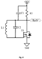
- Fig. 9 presents electrical schematics utilizing the resonant circuit.
- the inductor L1 is an equivalent of the inductor L1 from Fig. 8 .
- the resistance R (usually omitted in similar designs) plays an important role, which is described below.
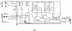
- Fig.10 and Fig. 11 zA practical implementation of the basic scheme from Fig.8 is shown in Fig.10 and Fig. 11 .
- the numbers in Fig.10 and Fig. 11 next to the inputs and outputs of the devices, are pin numbers.
- a transistor T1, a coil L1, a resistor R1 and a capacitance C1, form a generator circuit, of which amplitude of oscillation depends on the position of the target (marker) (1) in a form of an electrically conductive plate (corresponding to 1 in Fig.8 ).
- the amplitude of oscillation at the gate of the transistor T1 is compared in the circuit U2 to the level set by the voltage divider R2, R3, R4 and R5 .
- U2 is an analog comparator whose inputs (positive and negative) are chosen in a way that the comparator output is a logical zero if the signal from the generator is greater than the level obtained from the divider.
- Circuits U3 and U4 are Schmitt triggers and are used to produce signals (STROBE A and STROBE B in Fig. 8 ) which control flip-flops (corresponding to registers (6) and (7) in Fig. 8 ).
- the STROBE B signal generator is implemented on the chip U3.
- the STROBE A signal which is the delayed and inverted with respect to the STROB B signal, is realized on the chip U4.
- the transistor T2 and the resistor R5 are used to switch the required level (corresponding to switch (5) in Fig. 8 ).
- D1 LED diode lights up when the marker is found in the field of the coil L1.
- a variable resistor R3 is used to set the operating point (detection level) of the comparator U2, depending on the oscillations amplitude of the generator.
- FIG. 11 A microcontroller based implementation of schematics from Fig. 8 is presented in Fig. 11 .
- a datasheet for the microcontroller is available at manufacturers website:
- microcontroller implementation from Fig. 11 is equivalent to the solution from Fig. 10 that uses discrete electronic devices.
- microcontroller subsystem U2 is an 8-bit digital-to-analog converter (DAC), which is used to generate a reference voltage (Vref).
- DAC digital-to-analog converter
- This DAC in Fig. 11 is equivalent in functionality to the resistors R2, R3, R4, R5 and the transistor T2 in Fig. 10 .
- a change in the reference voltage depending on the expected state is accomplished by providing a proper numeric value to the input of the 8-bit DAC.
- a role of a 1-bit register, marked as 6 in Fig. 8 is played in the solution presented in Fig. 11 by one bit bit-field C1IF (Comparator 1 Interrupt Flag) of microcontroller register PIR2.
- the interrupt register PIR2 is used without enabling generation of interrupts.
- An equivalent function is achieved in Fig. 10 by elements U5A and U5B.
- the microcontroller used in schematics in Fig. 11 by default connects the output of the 8-bit DAC to the positive input of a used comparator.
- the signal from generator is therefore connected to negative (inverting) input of the comparator by pin RC1.
- Connector J3 in Fig. 11 is used to program the microcontroller
- Controlling signals STROBE A and STROBE B are implemented in Fig. 11 by a software, which relevant fragment written in C programming language is presented below:
- Fig. 12 shows a schematic view of a consumption meter (11) comprising a proximity sensor (10) and a conducive target element (1), fixed to the one of the wheels (12) (last wheel) in the form of a thin metal plate and.
Landscapes
- Physics & Mathematics (AREA)
- Fluid Mechanics (AREA)
- General Physics & Mathematics (AREA)
- Inductance-Capacitance Distribution Constants And Capacitance-Resistance Oscillators (AREA)
- Electronic Switches (AREA)
- Oscillators With Electromechanical Resonators (AREA)
Priority Applications (1)
| Application Number | Priority Date | Filing Date | Title |
|---|---|---|---|
| EP19152582.3A EP3509213A1 (de) | 2015-05-20 | 2016-05-09 | Verbrauchszähler |
Applications Claiming Priority (1)
| Application Number | Priority Date | Filing Date | Title |
|---|---|---|---|
| EP15461535.5A EP3096450A1 (de) | 2015-05-20 | 2015-05-20 | Elektrische schaltung eines schwingungsgenerators |
Related Child Applications (2)
| Application Number | Title | Priority Date | Filing Date |
|---|---|---|---|
| EP19152582.3A Division EP3509213A1 (de) | 2015-05-20 | 2016-05-09 | Verbrauchszähler |
| EP19152582.3A Previously-Filed-Application EP3509213A1 (de) | 2015-05-20 | 2016-05-09 | Verbrauchszähler |
Publications (1)
| Publication Number | Publication Date |
|---|---|
| EP3107207A1 true EP3107207A1 (de) | 2016-12-21 |
Family
ID=53264608
Family Applications (3)
| Application Number | Title | Priority Date | Filing Date |
|---|---|---|---|
| EP15461535.5A Ceased EP3096450A1 (de) | 2015-05-20 | 2015-05-20 | Elektrische schaltung eines schwingungsgenerators |
| EP19152582.3A Withdrawn EP3509213A1 (de) | 2015-05-20 | 2016-05-09 | Verbrauchszähler |
| EP16168773.6A Ceased EP3107207A1 (de) | 2015-05-20 | 2016-05-09 | Näherungssensor zur erkennung eines leitfähigen zielobjekts und verbrauchsmesser mit solch einem sensor |
Family Applications Before (2)
| Application Number | Title | Priority Date | Filing Date |
|---|---|---|---|
| EP15461535.5A Ceased EP3096450A1 (de) | 2015-05-20 | 2015-05-20 | Elektrische schaltung eines schwingungsgenerators |
| EP19152582.3A Withdrawn EP3509213A1 (de) | 2015-05-20 | 2016-05-09 | Verbrauchszähler |
Country Status (3)
| Country | Link |
|---|---|
| US (1) | US9608565B2 (de) |
| EP (3) | EP3096450A1 (de) |
| CN (1) | CN106169922B (de) |
Cited By (1)
| Publication number | Priority date | Publication date | Assignee | Title |
|---|---|---|---|---|
| EP3401648A1 (de) | 2017-05-09 | 2018-11-14 | Aiut Sp. z o.o. | Mechanisches trommelzählwerk für verbrauchsmesser |
Citations (11)
| Publication number | Priority date | Publication date | Assignee | Title |
|---|---|---|---|---|
| FR2001680A1 (de) * | 1968-02-09 | 1969-09-26 | Itt | |
| US3636470A (en) * | 1967-12-04 | 1972-01-18 | Olivetti & Co Spa | Variable inductance-controlled oscillator switching circuit |
| DE2450889A1 (de) * | 1974-10-25 | 1976-04-29 | Siemens Ag | Schaltungsanordnung fuer einen integrierbaren oszillator mit mos-feldeffekttransistoren |
| US4164706A (en) * | 1976-10-18 | 1979-08-14 | Nippon Soken, Inc. | Rotational position detector utilizing an FET blocking oscillator |
| DE3643970A1 (de) * | 1986-12-22 | 1988-06-30 | Siemens Ag | Sensoreinrichtung fuer eisenbahnanlagen |
| DE4021164C1 (en) * | 1990-07-03 | 1991-11-14 | Pepperl & Fuchs Gmbh, 6800 Mannheim, De | Inductive proximity circuit for machine tool - has oscillator transistor output signal compared with external signal for switching initiation |
| DE4102542A1 (de) * | 1991-01-29 | 1992-07-30 | Turck Werner Kg | Induktiver naeherungsschalter |
| US5610340A (en) * | 1995-06-23 | 1997-03-11 | New Jersey Institute Of Technology | Integrated pressure sensor with remote power source and remote read-out |
| EP0942531A2 (de) * | 1998-03-10 | 1999-09-15 | Lucent Technologies Inc. | Spannungsgesteuerte CMOS Oszillatorschaltung |
| US20100259282A1 (en) * | 2007-09-20 | 2010-10-14 | Panasonic Electric Works Co., Ltd. | Detector for proximity sensor and proximity sensor |
| US20140368286A1 (en) * | 2013-06-13 | 2014-12-18 | International Business Machines Corporation | Low Noise Voltage Controlled Oscillator |
Family Cites Families (17)
| Publication number | Priority date | Publication date | Assignee | Title |
|---|---|---|---|---|
| DE1548062C3 (de) * | 1964-06-03 | 1975-12-11 | Standard Elektrik Lorenz Ag, 7000 Stuttgart | Schaltungsanordnung für eine elektrische Uhr mit einem mechanischen Biege schwinger |
| GB1280656A (en) * | 1968-11-27 | 1972-07-05 | Wandel & Goltermann | Reactance circuit |
| US4287489A (en) * | 1979-09-19 | 1981-09-01 | General Electric Company | Amplitude limited varactor tuned L-C oscillator |
| JPS56131230A (en) * | 1980-03-18 | 1981-10-14 | Omron Tateisi Electronics Co | Contactless switch |
| FR2664973B1 (fr) * | 1990-07-20 | 1992-10-23 | Schlumberger Ind Sa | Dispositif de detection de rotation d'un element tournant tel que la turbine d'un compteur d'eau. |
| DK0660263T3 (da) * | 1993-12-23 | 2000-08-14 | Gas & Wassermesserfab Ag | Fremgangsmåde til tilvejebringelse af en elektrisk signaludlæsning fra et flercifret rulletælleværk til brug i et volumenmå |
| DE10006503A1 (de) * | 2000-02-14 | 2001-08-16 | Abb Research Ltd | Radzählwerk |
| US7026883B2 (en) * | 2004-03-12 | 2006-04-11 | Intel Corporation | Feedback loop for LC VCO |
| KR100615552B1 (ko) * | 2004-06-01 | 2006-08-25 | 학교법인 한국정보통신학원 | 직렬 교차 연결된 상보형 트랜지스터를 이용한 전압 제어발진기 및 이를 이용한 신호 송수신 장치 |
| TWI326979B (en) * | 2006-10-23 | 2010-07-01 | Univ Nat Taiwan Science Tech | Back gate coupled voltage control oscillator |
| JP2009105556A (ja) * | 2007-10-22 | 2009-05-14 | Murata Mfg Co Ltd | 高周波発振回路 |
| KR100952424B1 (ko) * | 2008-02-21 | 2010-04-14 | 한국전자통신연구원 | 트랜스포머의 커플링을 이용한 차동 전압 제어 발진기 및직교 전압 제어 발진기 |
| JP5181791B2 (ja) * | 2008-04-03 | 2013-04-10 | ソニー株式会社 | 電圧制御型可変周波数発振回路および信号処理回路 |
| US8044733B1 (en) * | 2008-08-07 | 2011-10-25 | Marvell International Ltd. | Stress tolerant differential colpitts voltage controlled oscillators |
| JP4929306B2 (ja) * | 2009-03-17 | 2012-05-09 | 株式会社東芝 | バイアス生成回路及び電圧制御発振器 |
| GB2483899A (en) * | 2010-09-24 | 2012-03-28 | Cambridge Silicon Radio Ltd | Digitally controllable LC oscillator with fine control resolution |
| CN104333379B (zh) * | 2014-11-05 | 2017-11-03 | 遵义师范学院 | 一种高线性频率调节范围的cmos压控振荡器 |
-
2015
- 2015-05-20 EP EP15461535.5A patent/EP3096450A1/de not_active Ceased
- 2015-07-28 CN CN201510450914.2A patent/CN106169922B/zh active Active
- 2015-08-06 US US14/820,515 patent/US9608565B2/en active Active
-
2016
- 2016-05-09 EP EP19152582.3A patent/EP3509213A1/de not_active Withdrawn
- 2016-05-09 EP EP16168773.6A patent/EP3107207A1/de not_active Ceased
Patent Citations (11)
| Publication number | Priority date | Publication date | Assignee | Title |
|---|---|---|---|---|
| US3636470A (en) * | 1967-12-04 | 1972-01-18 | Olivetti & Co Spa | Variable inductance-controlled oscillator switching circuit |
| FR2001680A1 (de) * | 1968-02-09 | 1969-09-26 | Itt | |
| DE2450889A1 (de) * | 1974-10-25 | 1976-04-29 | Siemens Ag | Schaltungsanordnung fuer einen integrierbaren oszillator mit mos-feldeffekttransistoren |
| US4164706A (en) * | 1976-10-18 | 1979-08-14 | Nippon Soken, Inc. | Rotational position detector utilizing an FET blocking oscillator |
| DE3643970A1 (de) * | 1986-12-22 | 1988-06-30 | Siemens Ag | Sensoreinrichtung fuer eisenbahnanlagen |
| DE4021164C1 (en) * | 1990-07-03 | 1991-11-14 | Pepperl & Fuchs Gmbh, 6800 Mannheim, De | Inductive proximity circuit for machine tool - has oscillator transistor output signal compared with external signal for switching initiation |
| DE4102542A1 (de) * | 1991-01-29 | 1992-07-30 | Turck Werner Kg | Induktiver naeherungsschalter |
| US5610340A (en) * | 1995-06-23 | 1997-03-11 | New Jersey Institute Of Technology | Integrated pressure sensor with remote power source and remote read-out |
| EP0942531A2 (de) * | 1998-03-10 | 1999-09-15 | Lucent Technologies Inc. | Spannungsgesteuerte CMOS Oszillatorschaltung |
| US20100259282A1 (en) * | 2007-09-20 | 2010-10-14 | Panasonic Electric Works Co., Ltd. | Detector for proximity sensor and proximity sensor |
| US20140368286A1 (en) * | 2013-06-13 | 2014-12-18 | International Business Machines Corporation | Low Noise Voltage Controlled Oscillator |
Non-Patent Citations (1)
| Title |
|---|
| EMAD HEGAZI ET AL: "A Filtering Technique to Lower LC Oscillator Phase Noise", IEEE JOURNAL OF SOLID-STATE CIRCUITS, IEEE SERVICE CENTER, PISCATAWAY, NJ, USA, vol. 36, no. 12, 1 December 2001 (2001-12-01), XP011061652, ISSN: 0018-9200 * |
Cited By (1)
| Publication number | Priority date | Publication date | Assignee | Title |
|---|---|---|---|---|
| EP3401648A1 (de) | 2017-05-09 | 2018-11-14 | Aiut Sp. z o.o. | Mechanisches trommelzählwerk für verbrauchsmesser |
Also Published As
| Publication number | Publication date |
|---|---|
| US20160344341A1 (en) | 2016-11-24 |
| EP3509213A1 (de) | 2019-07-10 |
| US9608565B2 (en) | 2017-03-28 |
| CN106169922A (zh) | 2016-11-30 |
| EP3096450A1 (de) | 2016-11-23 |
| CN106169922B (zh) | 2019-07-30 |
Similar Documents
| Publication | Publication Date | Title |
|---|---|---|
| US10156463B2 (en) | Fluid flow rate measuring device and water meter | |
| EP2558822B1 (de) | Elektromagnetisches verfahren zur erfassung der relativen position von zwei elementen anhand von gekoppelten abgestimmten schaltungen | |
| US20180090253A1 (en) | Integrated gap sensing electromagnetic reluctance actuator | |
| US20190383645A1 (en) | Initialization state determination of a magnetic multi-turn sensor | |
| CN102859872B (zh) | 用于传感器设备的电子部件、传感器设备和配置传感器设备的方法 | |
| EP2966410A1 (de) | Verfahren zur koppelung eines lc-sensors, entsprechendes system und computerprogrammprodukt | |
| US11143681B2 (en) | Method and device for determining a sensor coil inductance | |
| US9945690B2 (en) | Metering circuit including a time-varying reference and method | |
| EP3107207A1 (de) | Näherungssensor zur erkennung eines leitfähigen zielobjekts und verbrauchsmesser mit solch einem sensor | |
| US9638651B2 (en) | Method and circuit for evaluating a physical quantity detected by a sensor | |
| KR20180130584A (ko) | 비율―척도 셀프―커패시턴스―코드 변환기 | |
| CN108469595B (zh) | 磁场感测装置及感测方法 | |
| CN105319599A (zh) | 对接lc传感器的方法及其系统 | |
| CN105359416A (zh) | 电路、键和用于确定振荡特性的方法 | |
| US9246494B2 (en) | Metering circuit including a floating count window to determine a count | |
| Passenbrunner et al. | Simulation and optimization of an eddy current position sensor | |
| US11112439B2 (en) | Evaluating circuit, system, and method for evaluating a capacitive or inductive sensor | |
| CN114577855A (zh) | 一种基于感应电动势的磨粒检测方法及系统 | |
| Ortner et al. | Signal analysis in back bias speed sensor systems | |
| Babu et al. | An FFT based readout scheme for passive LC sensors | |
| KR20110039822A (ko) | 히스테리시스 보상 기능을 갖는 고주파 발진형 근접센서 | |
| JPWO2009001527A1 (ja) | 紙葉類磁気特性検出装置 | |
| Rossini et al. | Behavioral model of magnetic sensors for SPICE simulations | |
| CN119085767A (zh) | 无磁计量装置的计数方法、装置及电子设备 | |
| Korotkii | A model of a magnetomodulation converter |
Legal Events
| Date | Code | Title | Description |
|---|---|---|---|
| PUAI | Public reference made under article 153(3) epc to a published international application that has entered the european phase |
Free format text: ORIGINAL CODE: 0009012 |
|
| STAA | Information on the status of an ep patent application or granted ep patent |
Free format text: STATUS: THE APPLICATION HAS BEEN PUBLISHED |
|
| AK | Designated contracting states |
Kind code of ref document: A1 Designated state(s): AL AT BE BG CH CY CZ DE DK EE ES FI FR GB GR HR HU IE IS IT LI LT LU LV MC MK MT NL NO PL PT RO RS SE SI SK SM TR |
|
| AX | Request for extension of the european patent |
Extension state: BA ME |
|
| STAA | Information on the status of an ep patent application or granted ep patent |
Free format text: STATUS: REQUEST FOR EXAMINATION WAS MADE |
|
| 17P | Request for examination filed |
Effective date: 20170606 |
|
| RBV | Designated contracting states (corrected) |
Designated state(s): AL AT BE BG CH CY CZ DE DK EE ES FI FR GB GR HR HU IE IS IT LI LT LU LV MC MK MT NL NO PL PT RO RS SE SI SK SM TR |
|
| STAA | Information on the status of an ep patent application or granted ep patent |
Free format text: STATUS: EXAMINATION IS IN PROGRESS |
|
| 17Q | First examination report despatched |
Effective date: 20170922 |
|
| RIC1 | Information provided on ipc code assigned before grant |
Ipc: H03B 5/12 20060101ALI20190108BHEP Ipc: H03B 5/24 20060101AFI20190108BHEP |
|
| STAA | Information on the status of an ep patent application or granted ep patent |
Free format text: STATUS: THE APPLICATION HAS BEEN REFUSED |
|
| 18R | Application refused |
Effective date: 20190722 |