EP3107251A1 - Procédé et dispositif de transmission de paquet, et interface d'interconnexion - Google Patents
Procédé et dispositif de transmission de paquet, et interface d'interconnexion Download PDFInfo
- Publication number
- EP3107251A1 EP3107251A1 EP14891176.1A EP14891176A EP3107251A1 EP 3107251 A1 EP3107251 A1 EP 3107251A1 EP 14891176 A EP14891176 A EP 14891176A EP 3107251 A1 EP3107251 A1 EP 3107251A1
- Authority
- EP
- European Patent Office
- Prior art keywords
- packet
- node
- link
- sending
- active link
- Prior art date
- Legal status (The legal status is an assumption and is not a legal conclusion. Google has not performed a legal analysis and makes no representation as to the accuracy of the status listed.)
- Granted
Links
Images



Classifications
-
- H—ELECTRICITY
- H04—ELECTRIC COMMUNICATION TECHNIQUE
- H04L—TRANSMISSION OF DIGITAL INFORMATION, e.g. TELEGRAPHIC COMMUNICATION
- H04L45/00—Routing or path finding of packets in data switching networks
- H04L45/28—Routing or path finding of packets in data switching networks using route fault recovery
-
- H—ELECTRICITY
- H04—ELECTRIC COMMUNICATION TECHNIQUE
- H04L—TRANSMISSION OF DIGITAL INFORMATION, e.g. TELEGRAPHIC COMMUNICATION
- H04L1/00—Arrangements for detecting or preventing errors in the information received
- H04L1/12—Arrangements for detecting or preventing errors in the information received by using return channel
- H04L1/16—Arrangements for detecting or preventing errors in the information received by using return channel in which the return channel carries supervisory signals, e.g. repetition request signals
- H04L1/18—Automatic repetition systems, e.g. Van Duuren systems
-
- H—ELECTRICITY
- H04—ELECTRIC COMMUNICATION TECHNIQUE
- H04L—TRANSMISSION OF DIGITAL INFORMATION, e.g. TELEGRAPHIC COMMUNICATION
- H04L1/00—Arrangements for detecting or preventing errors in the information received
- H04L1/12—Arrangements for detecting or preventing errors in the information received by using return channel
- H04L1/16—Arrangements for detecting or preventing errors in the information received by using return channel in which the return channel carries supervisory signals, e.g. repetition request signals
- H04L1/18—Automatic repetition systems, e.g. Van Duuren systems
- H04L1/1867—Arrangements specially adapted for the transmitter end
- H04L1/1874—Buffer management
-
- H—ELECTRICITY
- H04—ELECTRIC COMMUNICATION TECHNIQUE
- H04L—TRANSMISSION OF DIGITAL INFORMATION, e.g. TELEGRAPHIC COMMUNICATION
- H04L1/00—Arrangements for detecting or preventing errors in the information received
- H04L1/12—Arrangements for detecting or preventing errors in the information received by using return channel
- H04L1/16—Arrangements for detecting or preventing errors in the information received by using return channel in which the return channel carries supervisory signals, e.g. repetition request signals
- H04L1/18—Automatic repetition systems, e.g. Van Duuren systems
- H04L1/1867—Arrangements specially adapted for the transmitter end
- H04L1/189—Transmission or retransmission of more than one copy of a message
-
- H—ELECTRICITY
- H04—ELECTRIC COMMUNICATION TECHNIQUE
- H04L—TRANSMISSION OF DIGITAL INFORMATION, e.g. TELEGRAPHIC COMMUNICATION
- H04L1/00—Arrangements for detecting or preventing errors in the information received
- H04L1/22—Arrangements for detecting or preventing errors in the information received using redundant apparatus to increase reliability
-
- H—ELECTRICITY
- H04—ELECTRIC COMMUNICATION TECHNIQUE
- H04L—TRANSMISSION OF DIGITAL INFORMATION, e.g. TELEGRAPHIC COMMUNICATION
- H04L45/00—Routing or path finding of packets in data switching networks
- H04L45/22—Alternate routing
-
- H—ELECTRICITY
- H04—ELECTRIC COMMUNICATION TECHNIQUE
- H04L—TRANSMISSION OF DIGITAL INFORMATION, e.g. TELEGRAPHIC COMMUNICATION
- H04L45/00—Routing or path finding of packets in data switching networks
- H04L45/74—Address processing for routing
Definitions
- the present invention relates to communications technologies, and in particular, to a packet transmission method and apparatus, and an interconnect interface.
- Computing nodes in the computing system generally interconnect with each other by using various types of interconnect interfaces.
- an interconnect interface used in the computing system needs to have high reliability.
- FIG. 1 is a schematic structural diagram of a retransmission manner of a retransmission Buffer in the prior art.
- Bidirectional communication is performed between chip A and chip B by using a link (Link). For example, chip A sends a packet to chip B.
- Link For example, chip A sends a packet to chip B.
- a transmit (TX) end of the link uses component A1 as a retransmission Buffer to back up the sent packet;
- component B2 is responsible for performing a cyclic redundancy check (Cyclic Redundancy Check, CRC) on the received packet, and sending a check result (whether the packet is correctly received) to component B3;
- component B3 is a retransmission management module of chip B, and is used to maintain a to-be-received pointer reptr, where the pointer is 0 after link initialization is completed, the reptr is increased by 1 each time one packet is correctly received, and after a maximum depth of the retransmission Buffer is reached, the pointer is reset to 0 for restarting accumulation.
- the Reptr pointer always points to a location of a next to-be-received packet in the retransmission Buffer of chip A.
- Component B3 is further used to initiate a retransmission request to chip A after a packet for which a CRC is incorrect is received, where the retransmission request carries a reptr recorded in chip B.
- Component A3 is a retransmission management module of chip A, and is responsible for driving, after receiving a retransmission request packet, a TX port to send to chip B again, a packet starting from an address of the reptr, so as to complete a retransmission procedure.
- chip B For a packet for which a CRC check is correct, chip B adds acknowledgment information to a packet sent by a TX end of the chip B and sends the packet to chip A. Chip A releases corresponding space in the retransmission Buffer after receiving the acknowledgment information, so as to form a head pointer (hptr) in the retransmission Buffer to indicate an oldest address that has not been released in the retransmission Buffer.
- hptr head pointer
- the foregoing retransmission Buffer retransmission technology only assures a scenario in which a recoverable failure occasionally occurs in a link.
- a system is suspended because a packet in the retransmission Buffer is not acknowledged by a counterpart.
- the system can continue to work only after the failure is manually removed and the link is reconnected, which cannot ensure reliability of an interconnect system.
- Embodiments of the present invention provide a packet transmission method and apparatus, and an interconnect interface, to implement sending a residual packet in a retransmission Buffer of a Link in which a failure is unrecoverable by using another standby link, so as to ensure high reliability of an interconnect system.
- an embodiment of the present invention provides a packet transmission method, including:
- the method further includes:
- the method before the sending, by the sending node, a packet to the receiving node by using the standby link, the method further includes:
- the packet in the retransmission buffer Buffer of the transmit end of the active link includes: a backup start packet, a residual packet in the retransmission Buffer, and a backup end packet, where the backup start packet carries an identity of the active link and a head pointer hptr in the retransmission Buffer, and when an address corresponding to the head pointer hptr is behind an address corresponding to the backup end packet, it indicates that the receiving node completely receives the packet in the retransmission buffer Buffer; and the sending, by the sending node, a packet to the receiving node by using the standby link includes: sequentially sending, by the sending node by using the standby link, the backup start packet, the residual packet, and the backup end packet.
- the standby link includes: a valid link directly connecting the sending node and the receiving node, or a valid link connecting the sending node and the receiving node by using a third node, where the third node is another node except the sending node and the receiving node.
- either of the active link and the standby link includes multiple serializer/deserializer SerDes interfaces, multiple source synchronization interfaces, or multiple low-speed parallel interfaces.
- an embodiment of the present invention provides a packet transmission method, including:
- the method before the sending, by the receiving node, the packet to the receive end of the active link, the method further includes:
- the packet in the retransmission buffer Buffer of the transmit end of the active link includes: a backup start packet, a residual packet in the retransmission Buffer, and a backup end packet, where the backup start packet carries an identity of the active link and a head pointer hptr in the retransmission Buffer;
- the receiving, by a receiving node, a packet sent by a sending node by using a standby link includes: sequentially receiving the backup start packet, the residual packet, and the backup end packet; and the sending, by the receiving node, the packet to the receive end of the active link includes:
- the backup start packet further carries the head pointer hptr in the retransmission Buffer, and after the sequentially sending, by the receiving node, the backup start packet, the residual packet, and the backup end packet to the receive end of the active link, the method further includes:
- the method further includes:
- the standby link includes: a valid link directly connecting the sending node and the receiving node, or a valid link connecting the sending node and the receiving node by using a third node, where the third node is another node except the sending node and the receiving node.
- either of the active link and the standby link includes multiple serializer/deserializer SerDes interfaces, multiple source synchronization interfaces, or multiple low-speed parallel interfaces.
- an embodiment of the present invention provides a packet transmission apparatus, including:
- the apparatus further includes:
- the apparatus further includes:
- the packet in the retransmission buffer Buffer of the transmit end of the active link includes: a backup start packet, a residual packet in the retransmission Buffer, and a backup end packet, where the backup start packet carries an identity of the active link and a head pointer hptr in the retransmission Buffer, and when an address corresponding to the head pointer hptr is behind an address corresponding to the backup end packet, it indicates that the receiving node completely receives the packet in the retransmission buffer Buffer; and the sending module is specifically configured to sequentially send, by using the standby link, the backup start packet, the residual packet, and the backup end packet.
- the standby link includes: a valid link directly connecting the sending node and the receiving node, or a valid link connecting the sending node and the receiving node by using a third node, where the third node is another node except the sending node and the receiving node.
- either of the active link and the standby link includes multiple serializer/deserializer SerDes interfaces, multiple source synchronization interfaces, or multiple low-speed parallel interfaces.
- an embodiment of the present invention provides a packet transmission apparatus, including:
- the apparatus further includes:
- the packet in the retransmission buffer Buffer of the transmit end of the active link includes: a backup start packet, a residual packet in the retransmission Buffer, and a backup end packet, where the backup start packet carries an identity of the active link and a head pointer hptr in the retransmission Buffer; the receiving module is specifically configured to sequentially receive the backup start packet, the residual packet, and the backup end packet; and the sending module is specifically configured to sequentially send, to the receive end of the active link, the backup start packet, the residual packet, and the backup end packet that are received by the receiving module.
- the apparatus further includes:
- the apparatus further includes:
- the standby link includes: a valid link directly connecting the sending node and the receiving node, or a valid link connecting the sending node and the receiving node by using a third node, where the third node is another node except the sending node and the receiving node.
- either of the active link and the standby link includes multiple serializer/deserializer SerDes interfaces, multiple source synchronization interfaces, or multiple low-speed parallel interfaces.
- an embodiment of the present invention provides an interconnect interface, including the packet transmission apparatus according to the foregoing third aspect, or any one of the first to the fifth possible implementation manners of the third aspect, and the packet transmission apparatus according to the foregoing fourth aspect, or any one of the first to the sixth possible implementation manners of the fourth aspect.
- packets in retransmission buffers Buffers of transmit ends of the links in which the failure is unrecoverable are sent to a standby link, so that these packets are sent, by using the standby link, to receive ends of the links in which the failure is unrecoverable, which greatly improves a capability of the interconnect system in preventing a sudden abnormal case, and ensures high reliability of the interconnect system.
- this process may be completed automatically by hardware without any extra software overhead or consumption of extra resources.
- an interconnect interface such as a computing node and a storage node.
- Nodes are connected to each other by using an interconnect interface, where the interconnect interface may be, for example, a serializer/deserializer (Serializer/Deserializer, SerDes) interface, a source synchronization interface, or a low-speed parallel interface, which is not limited in the present invention.
- SerDes serializer/deserializer
- SerDes serializer/Deserializer
- source synchronization interface a source synchronization interface
- low-speed parallel interface which is not limited in the present invention.
- Link link
- one Link is formed by multiple SerDes interfaces, and each Link may be an X4 link (X4 indicates that one Link is formed by four SerDes, and so on), an X8 link, or an X12 link.
- FIG. 2 is a schematic diagram of a first architecture of an interconnect system to which a packet transmission method is applicable according to the present invention.
- each Link may be formed by a group of X8 SerDes interfaces interconnected with each other by using an optical fiber, and the four Links share a bandwidth requirement between node A and node B.
- Each of node A and node B has a process (Process, PROC) module.
- the PROC module represents a module at an application/protocol layer, and is configured to: when the node properly works, send generated packets to transmit (Transmit, TX) ends of the four Links, and receive packets received by receive (Receive, RX) ends of the Links.
- node A communicates with node B.
- node A sends a packet to node B
- node A is a sending node
- node B is a receiving node
- node B sends a packet to node A
- node B is a sending node
- node A is a receiving node.
- a sending node and a receiving node are merely two relative concepts. For example, node A sends a packet to node B.
- the embodiments of the present invention provide a packet transmission method with dynamic mutual backup of multiple Links, which ensures that, in a normal case, the Links share a bandwidth requirement of an entire system.
- a residual packet in a retransmission Buffer of the faulty Link is sent to a receive end by using another standby link, so as to ensure high reliability of an interconnect system.
- FIG. 3 For details, refer to FIG. 3 .
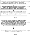
- FIG. 3 is a flowchart of a first embodiment of a packet transmission method according to the present invention.
- the present invention is described in detail from a perspective of a sending node.
- This embodiment of the present invention is applicable to a scenario in which an unrecoverable failure occurs in some Links between any two nodes in an interconnect system, and real-time quality and reliability of the interconnect system need to be ensured.
- node A is a sending node
- node B is a receiving node.
- this embodiment includes the following steps:
- Whether an unrecoverable failure occurs in a Link is determined by a state machine of the Link.
- a state machine (not shown in the figure) of each Link of node A determines whether an unrecoverable failure occurs in the corresponding Link, that is, whether a failure that cannot be recovered by the link occurs, for example, a failure such as removal of an optical fiber.
- a link in which an unrecoverable failure occurs is referred to as an active link.
- the sending node selects, from the multiple communication links, at least one standby link except the active link.
- the sending node may configure, by default, a Link as a standby link in advance, and ensure that the standby link is always in a valid state; or may select at least one Link from multiple valid Links as a standby link according to a priority, a load condition, and the like, and send, to the standby link, a residual packet in a retransmission Buffer of a link in which an unrecoverable failure occurs.
- the sending node sends a packet to the receiving node by using the standby link, so that the receiving node sends the packet to a receive end of the active link, where the packet is a packet in a retransmission buffer Buffer of a transmit end of the active link.
- these faulty Links may also be sorted according to a priority, a load condition, importance of a packet, and the like, and a standby link is selected for each Link according to the sorting.
- importance of a packet as an example, it is assumed that importance of Link0-Link3 according to importance of packets carried is successively Link0, Link1, Link2, and Link3, and priorities of Link0-Link3 as standby links are Link3, Link2, Link1, and Link0 successively.
- a standby link Link2 is first selected for Link0, and a standby link Link0 is then selected for Link3; or Link2 is used as a standby link of Link0 and Link3, and after a residual packet in a retransmission Buffer of Link0 is completely sent, a residual packet in a retransmission Buffer of Link3 is then sent to Link2.
- a sending node selects a standby link, and sends, by using the standby link, packets in retransmission buffers Buffers of transmit ends of the links in which the failure is unrecoverable to receive ends of the links in which the failure is unrecoverable, which greatly improves a capability of the interconnect system in preventing a sudden abnormal case, and ensures high reliability of the interconnect system.
- this process may be completed automatically by hardware without any extra software overhead or consumption of extra resources.
- FIG. 4 is a flowchart of a second embodiment of a packet transmission method according to the present invention.
- the present invention is described in detail from a perspective of a receiving node.
- This embodiment of the present invention is applicable to a scenario in which an unrecoverable failure occurs in some Links between any two nodes in an interconnect system, and real-time quality and reliability of the interconnect system need to be ensured.
- node A is a sending node
- node B is a receiving node.
- this embodiment includes the following steps:
- the receiving node receives a packet sent by the sending node by using a standby link, where the packet is a packet in a retransmission buffer Buffer of a transmit end of an active link; the active link is any one of multiple communication links between the sending node and the receiving node; and the standby link is at least one another link in the multiple communication links except the active link.
- step 101 in FIG. 3 for concepts related to the active link and the like, refer to step 101 in FIG. 3 , and details are not described herein again.
- the receiving node sends, in the receiving node, the packet from the standby link to a receive end of the active link.
- Link3 of node A sends residual packets in a retransmission Buffer of a transmit end of Link3 to a transmit end of Link2, and the transmit end of Link2 sends these residual packets to a receive end of Link2.
- the residual packets can be sent from node A to node B.
- the receive end of Link2 further sends the received packets to a receive end of Link3.
- a sending node when determining that an unrecoverable failure occurs in some of the Links, a sending node sends, to a standby link, packets in retransmission buffers Buffers of transmit ends of the links in which the failure is unrecoverable; correspondingly, a receiving node receives these packets, and sends these packets to receive ends of the links in which the failure is unrecoverable, which greatly improves a capability of the interconnect system in preventing a sudden abnormal case, and ensures high reliability of the interconnect system.
- this process may be completed automatically by hardware without any extra software overhead or consumption of extra resources.
- FIG. 3 and FIG. 4 the present invention is described in detail separately from a perspective of a sending node and a perspective of a receiving node.
- the following describes the present invention in detail from a perspective of interaction between a sending node and a receiving node.
- FIG. 5 is a schematic diagram of a second architecture of an interconnect system to which a packet transmission method is applicable according to the present invention.
- Link0 Link0 between node A and node B
- Link0 is an active link
- FIG. 5 detailed descriptions of components in a packet transmission process provided in this embodiment of the present invention are as follows:
- a packet transmission process provided in this embodiment of the present invention is as follows:
- the backup management unit A selects a link from valid links as a standby link of Link0.
- a specific selecting process refer to step 102 in FIG. 3 , and details are not described herein again.
- Step 4 The backup management unit A sets a channel between the transmit end of Link0 and a transmit end of the standby link.
- Links are connected by using site units, and each site unit is connected to a transmit end of a current Link.
- a channel between Links connected by using site units is referred to as a horizontal channel
- a channel that connects to each site unit and a transmit end of a current Link is referred to as a current Link transmit channel
- each site unit selects, by using a channel selecting switch, to enable the horizontal channel or the current Link transmit channel.
- the backup management unit A enables a channel selecting switch of each site unit according to the selected standby Link.
- the standby Link selected in step 3.5 is Link1; therefore, in this step, the backup management unit A enables a channel selecting switch of a horizontal channel between A02 and A12, and enables a channel selecting switch of a channel between A12 and a transmit end of Link1, that is, the backup management unit A enables a current Link transmit channel of Link1.
- the standby Link selected in step 3.5 is Link2; therefore, in this step, the backup management unit A enables a channel selecting switch of a horizontal channel between A02 and A12 and a channel selecting switch of a horizontal channel between A12 and A22, disables a current Link transmit channel of Link1, and enables a current Link transmit channel of Link2.
- Step 5 The backup management unit A instructs the active link Link0 to send the packet in the retransmission Buffer to the standby link.
- the backup management unit A instructs the active link Link0 to send the packet in the retransmission Buffer A01 by using the set channel, and at the same time, instructs Link1 to stop the PROC_A module from sending a new packet to Link1.
- a residual packet in the retransmission Buffer A01 of Link0 flows to the site unit A02, flows from A02 to the standby Link, that is, the site unit A12 of Link1, and finally flows from A12 to the transmit end of Link1.
- the standby Link is Link2
- a residual packet in the retransmission Buffer A01 flows to the site A02, then flows to the site unit A22 of Link2, and flows from A22 to a transmit end of Link2.
- the packet in the retransmission buffer Buffer of the transmit end of the active link Link0 includes: a backup start packet, a residual packet in the retransmission Buffer, and a backup end packet, where the backup start packet carries an identity of Link0 and a head pointer hptr in the retransmission Buffer.
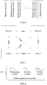
- FIG. 6 is a diagram of a packet sending process in the third embodiment of the packet transmission method according to the present invention.
- step 6 to step 11 the present invention is described in detail by using Link1 as a standby Link.
- Step 6 The packet in the retransmission Buffer A01 is transmitted to the site unit A12 of Link1 by using a horizontal channel, and is sent on the current Link transmit channel of Link1, that is, from a transmit end of Link1; in addition, the packet in the retransmission Buffer A01 is written into the retransmission Buffer A11 of Link1.
- Step 7 After a receive end of Link1 of node B receives a backup start packet, the distribution unit B13 of Link1 of node B parses the backup start packet, records this event, and also sets, according to information in the backup start packet, a channel between the receive end of Link1 and the receive end of the active link Link0, that is, the distribution unit B 13 enables a current Link transmit channel between B 13 and B12, and a horizontal channel between B12 and B02.
- Step 8 Link1 of node B sends, to the receive end of Link0 of node B by using a path: B13->B12->B02, the packet received by the receive end.
- Step 9 The screening unit B04 of Link0 of node B counts, according to a record of a head pointer reptr in the backup start packet, a received residual packet so as to find a packet corresponding to a to-be-received reptr of the screening unit B04, where a packet following the packet corresponding to the to-be-received pointer reptr is a packet in the retransmission buffer Buffer; and sends the packet received after the packet corresponding to the to-be-received pointer reptr to the PROC_B module; in this way, the PROC_B module of node B unconsciously receives consecutive correct packets.
- Step 10 When receiving a backup end packet, the screening unit B02 of node B restores a state of a switch channel of Link1, so that a packet subsequently received by Link1 is a packet that is sent by the PROC_A module and that belongs to Link1.
- Step 11 After a backup end packet buffered in the retransmission Buffer A11 of Link1 of node A is released after a normal ACK, that is, after an address of the hptr is behind an address for storing the backup end packet, it indicates that the receive end of Link0 of node B has completely and correctly received all packets in the buffer Buffer A01 of the transmit end of Link0 in node A; in this case, Link1 sends, to the backup management unit A, completion indication information to report end of this retransmission procedure.
- a Link in which an unrecoverable failure occurs is a Link between two directly connected nodes, and a standby link is a valid link directly connecting the sending node and the receiving node.
- the standby link may also be a valid link connecting the sending node and the receiving node by using a third node, where the third node is another node except the sending node and the receiving node.
- FIG. 7 is a schematic diagram of a third architecture of an interconnect system to which a packet transmission method is applicable according to the present invention.
- each node has three Links that are respectively connected to the other three nodes.
- node A has Link0, Link1, and Link2 that are respectively connected to node B, node D, and node C
- node B has Link0, Link4, and Link5 that are respectively connected to node A, node D, and node C and so on
- the nodes form a fully-interconnected system by using these Links.
- a residual packet in a retransmission Buffer of Link0 in node A may be backed up twice by using Link1 and Link4 and retransmitted to a receive end of Link0 in node B, or may be backed up three times by using Link1, Link3, and Link5 and retransmitted to a receive end of Link0 in node B.
- the packet transmission method provided in this embodiment of the present invention is applicable to an interconnect system that has a requirement for high bandwidth and high data stability, such as a computing system, a storage system, or the like, and is applicable to any interconnect system based on a communications interface protocol without error retransmission at a protocol layer, such as a cache coherence non-uniform memory access (Cache Coherence-Non Uniform Memory Access, CC-NUMA) system.
- CC-NUMA cache coherence non-uniform memory access
- An interconnect protocol requirement of the CC-NUMA system is as follows: An interconnect interface data link layer needs to ensure complete reliable transmission of a packet. Any error packet and packet loss may probably cause breakdown of an entire system.
- FIG. 8 is a schematic structural diagram of a first embodiment of a packet transmission apparatus according to the present invention.
- the packet transmission apparatus provided in this embodiment is an apparatus embodiment corresponding to the embodiment in FIG. 3 of the present invention. A specific implementation process is not repeated herein.
- a packet transmission apparatus 100 provided in this embodiment specifically includes:
- packets in retransmission buffers Buffers of transmit ends of the links in which the failure is unrecoverable are sent to a standby link, so that these packets are sent, by using the standby link, to receive ends of the links in which the failure is unrecoverable, which greatly improves a capability of the interconnect system in preventing a sudden abnormal case, and ensures high reliability of the interconnect system.
- this process may be completed automatically by hardware without any extra software overhead or consumption of extra resources.
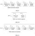
- FIG. 9 is a schematic structural diagram of a second embodiment of a packet transmission apparatus according to the present invention. As shown in FIG. 8 , based on the structure of the apparatus shown in FIG. 8 , optionally, the packet transmission apparatus 100 in this embodiment further includes:
- the packet transmission apparatus 100 further includes:
- the packet in the retransmission buffer Buffer of the transmit end of the active link includes: a backup start packet, a residual packet in the retransmission Buffer, and a backup end packet, where the backup start packet carries an identity of the active link and a head pointer hptr in the retransmission Buffer, and when an address corresponding to the head pointer hptr is behind an address corresponding to the backup end packet, it indicates that the receiving node completely receives the packet in the retransmission buffer Buffer; and the sending module 13 is specifically configured to sequentially send, by using the standby link, the backup start packet, the residual packet, and the backup end packet.
- the standby link includes: a valid link directly connecting the sending node and the receiving node, or a valid link connecting the sending node and the receiving node by using a third node, where the third node is another node except the sending node and the receiving node.
- either of the active link and the standby link includes multiple serializer/deserializer SerDes interfaces, multiple source synchronization interfaces, or multiple low-speed parallel interfaces.
- FIG. 10 is a schematic structural diagram of a third embodiment of a packet transmission apparatus according to the present invention.
- the packet transmission apparatus provided in this embodiment is an apparatus embodiment corresponding to the embodiment in FIG. 4 of the present invention. A specific implementation process is not repeated herein.
- a packet transmission apparatus 200 provided in this embodiment specifically includes:
- a sending node when determining that an unrecoverable failure occurs in some of the Links, a sending node sends, to a standby link, packets in retransmission buffers Buffers of transmit ends of the links in which the failure is unrecoverable; correspondingly, a receiving node receives these packets, and sends these packets to receive ends of the links in which the failure is unrecoverable, which greatly improves a capability of the interconnect system in preventing a sudden abnormal case, and ensures high reliability of the interconnect system.
- this process may be completed automatically by hardware without any extra software overhead or consumption of extra resources.
- FIG. 11 is a schematic structural diagram of a fourth embodiment of a packet transmission apparatus according to the present invention. As shown in FIG. 11 , based on the structure of the apparatus shown in FIG. 10 , optionally, the packet transmission apparatus 200 in this embodiment further includes:
- the packet in the retransmission buffer Buffer of the transmit end of the active link includes: a backup start packet, a residual packet in the retransmission Buffer, and a backup end packet, where the backup start packet carries an identity of the active link and a head pointer hpt in the retransmission Buffer, where the receiving module 21 is specifically configured to sequentially receive the backup start packet, the residual packet, and the backup end packet; and the sending module 22 is specifically configured to sequentially send, to the receive end of the active link, the backup start packet, the residual packet, and the backup end packet that are received by the receiving module 21.
- the packet transmission apparatus 200 further includes:
- the packet transmission apparatus 200 further includes:
- the standby link includes: a valid link directly connecting the sending node and the receiving node, or a valid link connecting the sending node and the receiving node by using a third node, where the third node is another node except the sending node and the receiving node.
- either of the active link and the standby link includes multiple serializer/deserializer SerDes interfaces, multiple source synchronization interfaces, or multiple low-speed parallel interfaces.
- FIG. 12 is a schematic structural diagram of a fifth embodiment of a packet transmission apparatus according to the present invention.
- a packet transmission apparatus 300 provided in this embodiment includes a processor 31 and a memory 32.
- the packet transmission apparatus 300 may further include a transmitter 33 and a receiver 34.
- the transmitter 33 and the receiver 34 may be connected to the processor 31.
- the transmitter 33 is configured to send data or information
- the receiver 34 is configured to receive data or information
- the memory 32 stores an executable instruction.
- the processor 31 communicates with the memory 32, and the processor 31 invokes the executable instruction in the memory 32, so as to execute the method embodiment shown in FIG. 3 . Implementation principles and technical effects of the apparatus are similar, and are not repeated herein.
- FIG. 13 is a schematic structural diagram of a sixth embodiment of a packet transmission apparatus according to the present invention.
- a packet transmission apparatus 400 provided in this embodiment includes a processor 41 and a memory 42.
- the packet transmission apparatus 400 may further include a transmitter 43 and a receiver 44.
- the transmitter 43 and the receiver 44 may be connected to the processor 41.
- the transmitter 43 is configured to send data or information
- the receiver 44 is configured to receive data or information
- the memory 42 stores an executable instruction.
- the processor 41 communicates with the memory 42, and the processor 41 invokes the executable instruction in the memory 42, so as to execute the method embodiment shown in FIG. 4 . Implementation principles and technical effects of the apparatus are similar, and are not repeated herein.
- an embodiment of the present invention further provides an interconnect interface, including the packet transmission apparatus shown in the foregoing FIG. 8 , FIG. 9 , or FIG. 12 , and the packet transmission apparatus shown in the foregoing FIG. 10, FIG. 11 , or FIG. 13 . Specific working principles are not described herein again.
- the program may be stored in a computer-readable storage medium.
- the foregoing storage medium includes: any medium that can store program code, such as a ROM, a RAM, a magnetic disk, or an optical disc.
Landscapes
- Engineering & Computer Science (AREA)
- Computer Networks & Wireless Communication (AREA)
- Signal Processing (AREA)
- Data Exchanges In Wide-Area Networks (AREA)
- Communication Control (AREA)
Applications Claiming Priority (2)
| Application Number | Priority Date | Filing Date | Title |
|---|---|---|---|
| CN201410189288.1A CN103957155B (zh) | 2014-05-06 | 2014-05-06 | 报文传输方法、装置及互联接口 |
| PCT/CN2014/088961 WO2015169057A1 (fr) | 2014-05-06 | 2014-10-20 | Procédé et dispositif de transmission de paquet, et interface d'interconnexion |
Publications (3)
| Publication Number | Publication Date |
|---|---|
| EP3107251A1 true EP3107251A1 (fr) | 2016-12-21 |
| EP3107251A4 EP3107251A4 (fr) | 2017-03-29 |
| EP3107251B1 EP3107251B1 (fr) | 2019-08-28 |
Family
ID=51334383
Family Applications (1)
| Application Number | Title | Priority Date | Filing Date |
|---|---|---|---|
| EP14891176.1A Active EP3107251B1 (fr) | 2014-05-06 | 2014-10-20 | Procédé et dispositif de transmission de paquet |
Country Status (4)
| Country | Link |
|---|---|
| US (1) | US10348616B2 (fr) |
| EP (1) | EP3107251B1 (fr) |
| CN (1) | CN103957155B (fr) |
| WO (1) | WO2015169057A1 (fr) |
Families Citing this family (14)
| Publication number | Priority date | Publication date | Assignee | Title |
|---|---|---|---|---|
| US8125907B2 (en) | 2008-06-12 | 2012-02-28 | Talari Networks Incorporated | Flow-based adaptive private network with multiple WAN-paths |
| US9069727B2 (en) | 2011-08-12 | 2015-06-30 | Talari Networks Incorporated | Adaptive private network with geographically redundant network control nodes |
| US10447543B2 (en) * | 2009-06-11 | 2019-10-15 | Talari Networks Incorporated | Adaptive private network (APN) bandwith enhancements |
| CN103957155B (zh) * | 2014-05-06 | 2018-01-23 | 华为技术有限公司 | 报文传输方法、装置及互联接口 |
| CN105634694B (zh) * | 2014-11-03 | 2019-09-03 | 杭州华为数字技术有限公司 | 一种节点间传输数据的方法和系统 |
| US10291299B2 (en) * | 2015-09-07 | 2019-05-14 | Kabushiki Kaisha Toshiba | Wireless communication device |
| CN108123901B (zh) * | 2016-11-30 | 2020-12-29 | 新华三技术有限公司 | 一种报文传输方法和装置 |
| CN110213176B (zh) * | 2019-06-28 | 2022-03-29 | 北京东土军悦科技有限公司 | 交换机的报文处理方法、装置、设备及介质 |
| US11082304B2 (en) | 2019-09-27 | 2021-08-03 | Oracle International Corporation | Methods, systems, and computer readable media for providing a multi-tenant software-defined wide area network (SD-WAN) node |
| CN111586099B (zh) * | 2020-04-01 | 2023-03-24 | 烽火通信科技股份有限公司 | 一种跨节点的数据备份同步方法及系统 |
| US11483228B2 (en) | 2021-01-29 | 2022-10-25 | Keysight Technologies, Inc. | Methods, systems, and computer readable media for network testing using an emulated data center environment |
| CN115905036A (zh) * | 2021-09-30 | 2023-04-04 | 华为技术有限公司 | 一种数据访问系统、方法及相关设备 |
| WO2023122995A1 (fr) * | 2021-12-28 | 2023-07-06 | 华为技术有限公司 | Procédé et dispositif de transmission de paquets |
| CN120455415A (zh) * | 2024-02-07 | 2025-08-08 | 华为技术有限公司 | 数据重传方法、数据传输系统以及网络装置 |
Family Cites Families (17)
| Publication number | Priority date | Publication date | Assignee | Title |
|---|---|---|---|---|
| US6160808A (en) * | 1997-12-18 | 2000-12-12 | 3Com Corporation | Technique for transmitting incoming multi-link point-to-point (PPP) packet traffic over multiple outgoing links in a multi-link bundle |
| JP3830819B2 (ja) * | 2000-02-01 | 2006-10-11 | 富士通株式会社 | 情報転送装置 |
| US6606379B2 (en) * | 2001-06-01 | 2003-08-12 | Tekelec | Methods and systems for collapsing signal transfer point (STP) infrastructure in a signaling network |
| US20060187841A1 (en) * | 2005-02-24 | 2006-08-24 | Tekelec | Methods, systems, and computer program products for suppressing congestion control at a signaling system 7 network node |
| US7898944B2 (en) * | 2005-12-14 | 2011-03-01 | Cisco Technology, Inc. | Smart mechanism for multi-client bidirectional optical channel protection scheme |
| JP4587053B2 (ja) * | 2007-08-28 | 2010-11-24 | 日本電気株式会社 | 通信装置、通信システム、パケット欠落検出方法、およびパケット欠落検出プログラム |
| US7792014B2 (en) * | 2007-09-28 | 2010-09-07 | Integrated Device Technology, Inc. | Method of skipping nullified packets during mass replay from replay buffer |
| CN101277269A (zh) * | 2008-05-06 | 2008-10-01 | 杭州华三通信技术有限公司 | 实现可靠通信的终端、终端切换方法及系统和适用该系统的方法 |
| US8094569B2 (en) * | 2008-12-05 | 2012-01-10 | Cisco Technology, Inc. | Failover and failback of communication between a router and a network switch |
| CN102082696B (zh) * | 2011-03-10 | 2012-11-21 | 中控科技集团有限公司 | 一种冗余网络系统以及基于该系统的报文发送方法 |
| US20130003549A1 (en) * | 2011-06-30 | 2013-01-03 | Broadcom Corporation | Resilient Hashing for Load Balancing of Traffic Flows |
| US9762434B2 (en) * | 2011-08-12 | 2017-09-12 | Rambus Inc. | Temporal redundancy |
| JP5987319B2 (ja) * | 2012-01-06 | 2016-09-07 | 富士ゼロックス株式会社 | 送受信システム及びプログラム |
| JP5883743B2 (ja) * | 2012-08-20 | 2016-03-15 | 株式会社日立製作所 | パケット通信網における通信途絶時間短縮方法 |
| US9154370B2 (en) * | 2012-11-05 | 2015-10-06 | Cisco Technology, Inc. | Seamless multipath retransmission using source-routed tunnels |
| CN103746912B (zh) * | 2014-01-03 | 2017-04-12 | 杭州华三通信技术有限公司 | 一种基于子环链路的数据报文传输方法和设备 |
| CN103957155B (zh) * | 2014-05-06 | 2018-01-23 | 华为技术有限公司 | 报文传输方法、装置及互联接口 |
-
2014
- 2014-05-06 CN CN201410189288.1A patent/CN103957155B/zh active Active
- 2014-10-20 WO PCT/CN2014/088961 patent/WO2015169057A1/fr not_active Ceased
- 2014-10-20 EP EP14891176.1A patent/EP3107251B1/fr active Active
-
2016
- 2016-10-10 US US15/289,246 patent/US10348616B2/en active Active
Also Published As
| Publication number | Publication date |
|---|---|
| WO2015169057A1 (fr) | 2015-11-12 |
| EP3107251B1 (fr) | 2019-08-28 |
| US20170026280A1 (en) | 2017-01-26 |
| CN103957155A (zh) | 2014-07-30 |
| CN103957155B (zh) | 2018-01-23 |
| EP3107251A4 (fr) | 2017-03-29 |
| US10348616B2 (en) | 2019-07-09 |
Similar Documents
| Publication | Publication Date | Title |
|---|---|---|
| US10348616B2 (en) | Packet transmission method and apparatus, and interconnect interface | |
| US11252067B2 (en) | Techniques for using frame deep loopback capabilities for extended link diagnostics in fibre channel storage area networks | |
| US10659292B2 (en) | Arbitration method, apparatus, and system used in active-active data centers | |
| US20080117827A1 (en) | Method and system for verifying connectivity of logical link | |
| CN102984059B (zh) | 千兆以太网冗余网卡及其链路切换条件判定结果控制方法 | |
| US9197373B2 (en) | Method, apparatus, and system for retransmitting data packet in quick path interconnect system | |
| CN112214441A (zh) | 基于串行总线轮询协议的通信切换方法、设备和系统 | |
| CN102882704B (zh) | 一种issu的软重启升级过程中的链路保护方法和设备 | |
| JP2024517128A (ja) | クロック同期エッジベースのネットワーク機能 | |
| JP2024517128A5 (fr) | ||
| US8279762B2 (en) | Interface switching method and device | |
| CN111756588B (zh) | 通信链路检测方法及相关装置 | |
| US10230625B2 (en) | Information processing apparatus, information processing system, and communication device | |
| JP2005286589A (ja) | イーサネット・インタフェースを具備するネットワーク機器 | |
| EP2698944B1 (fr) | Procédé dynamique d'ajustement d'un lien et dispositif de gestion d'un lien | |
| WO2017000737A1 (fr) | Procédé de vérification de transmission, nœud, système et support de stockage informatique | |
| CN114884767A (zh) | 一种同步双冗余can总线通信系统、方法、设备及介质 | |
| US20160080111A1 (en) | Receiver, transmitter and data transmission system | |
| WO2021057350A1 (fr) | Procédé, appareil, dispositif et support de réponse de défaillance de liaison ethernet flexible | |
| EP2775678B1 (fr) | Port de diagnostic pour test de liaison et de noeud inter commutateurs électriques, optiques et modes de bouclage distant | |
| JP6134720B2 (ja) | 接続方法 | |
| JP5104773B2 (ja) | データ転送システム、データ転送装置およびデータ転送方法 | |
| JPH02100538A (ja) | ローカルエリアネットワークのデータ通信方法 | |
| CN108616461B (zh) | 一种策略切换方法及装置 | |
| US11996932B2 (en) | Active-active TDM PW with asymmetry control |
Legal Events
| Date | Code | Title | Description |
|---|---|---|---|
| PUAI | Public reference made under article 153(3) epc to a published international application that has entered the european phase |
Free format text: ORIGINAL CODE: 0009012 |
|
| STAA | Information on the status of an ep patent application or granted ep patent |
Free format text: STATUS: REQUEST FOR EXAMINATION WAS MADE |
|
| 17P | Request for examination filed |
Effective date: 20160916 |
|
| AK | Designated contracting states |
Kind code of ref document: A1 Designated state(s): AL AT BE BG CH CY CZ DE DK EE ES FI FR GB GR HR HU IE IS IT LI LT LU LV MC MK MT NL NO PL PT RO RS SE SI SK SM TR |
|
| AX | Request for extension of the european patent |
Extension state: BA ME |
|
| A4 | Supplementary search report drawn up and despatched |
Effective date: 20170301 |
|
| RIC1 | Information provided on ipc code assigned before grant |
Ipc: H04L 12/707 20130101AFI20170223BHEP Ipc: H04L 1/18 20060101ALI20170223BHEP Ipc: H04L 12/703 20130101ALI20170223BHEP |
|
| DAX | Request for extension of the european patent (deleted) | ||
| RAP1 | Party data changed (applicant data changed or rights of an application transferred) |
Owner name: HUAWEI TECHNOLOGIES CO., LTD. |
|
| GRAP | Despatch of communication of intention to grant a patent |
Free format text: ORIGINAL CODE: EPIDOSNIGR1 |
|
| STAA | Information on the status of an ep patent application or granted ep patent |
Free format text: STATUS: GRANT OF PATENT IS INTENDED |
|
| INTG | Intention to grant announced |
Effective date: 20190319 |
|
| GRAS | Grant fee paid |
Free format text: ORIGINAL CODE: EPIDOSNIGR3 |
|
| GRAA | (expected) grant |
Free format text: ORIGINAL CODE: 0009210 |
|
| STAA | Information on the status of an ep patent application or granted ep patent |
Free format text: STATUS: THE PATENT HAS BEEN GRANTED |
|
| AK | Designated contracting states |
Kind code of ref document: B1 Designated state(s): AL AT BE BG CH CY CZ DE DK EE ES FI FR GB GR HR HU IE IS IT LI LT LU LV MC MK MT NL NO PL PT RO RS SE SI SK SM TR |
|
| REG | Reference to a national code |
Ref country code: GB Ref legal event code: FG4D |
|
| REG | Reference to a national code |
Ref country code: CH Ref legal event code: EP |
|
| REG | Reference to a national code |
Ref country code: AT Ref legal event code: REF Ref document number: 1173799 Country of ref document: AT Kind code of ref document: T Effective date: 20190915 |
|
| REG | Reference to a national code |
Ref country code: IE Ref legal event code: FG4D |
|
| REG | Reference to a national code |
Ref country code: DE Ref legal event code: R096 Ref document number: 602014052759 Country of ref document: DE |
|
| REG | Reference to a national code |
Ref country code: NL Ref legal event code: MP Effective date: 20190828 |
|
| REG | Reference to a national code |
Ref country code: LT Ref legal event code: MG4D |
|
| PG25 | Lapsed in a contracting state [announced via postgrant information from national office to epo] |
Ref country code: LT Free format text: LAPSE BECAUSE OF FAILURE TO SUBMIT A TRANSLATION OF THE DESCRIPTION OR TO PAY THE FEE WITHIN THE PRESCRIBED TIME-LIMIT Effective date: 20190828 Ref country code: NL Free format text: LAPSE BECAUSE OF FAILURE TO SUBMIT A TRANSLATION OF THE DESCRIPTION OR TO PAY THE FEE WITHIN THE PRESCRIBED TIME-LIMIT Effective date: 20190828 Ref country code: BG Free format text: LAPSE BECAUSE OF FAILURE TO SUBMIT A TRANSLATION OF THE DESCRIPTION OR TO PAY THE FEE WITHIN THE PRESCRIBED TIME-LIMIT Effective date: 20191128 Ref country code: NO Free format text: LAPSE BECAUSE OF FAILURE TO SUBMIT A TRANSLATION OF THE DESCRIPTION OR TO PAY THE FEE WITHIN THE PRESCRIBED TIME-LIMIT Effective date: 20191128 Ref country code: SE Free format text: LAPSE BECAUSE OF FAILURE TO SUBMIT A TRANSLATION OF THE DESCRIPTION OR TO PAY THE FEE WITHIN THE PRESCRIBED TIME-LIMIT Effective date: 20190828 Ref country code: HR Free format text: LAPSE BECAUSE OF FAILURE TO SUBMIT A TRANSLATION OF THE DESCRIPTION OR TO PAY THE FEE WITHIN THE PRESCRIBED TIME-LIMIT Effective date: 20190828 Ref country code: PT Free format text: LAPSE BECAUSE OF FAILURE TO SUBMIT A TRANSLATION OF THE DESCRIPTION OR TO PAY THE FEE WITHIN THE PRESCRIBED TIME-LIMIT Effective date: 20191230 Ref country code: FI Free format text: LAPSE BECAUSE OF FAILURE TO SUBMIT A TRANSLATION OF THE DESCRIPTION OR TO PAY THE FEE WITHIN THE PRESCRIBED TIME-LIMIT Effective date: 20190828 |
|
| PG25 | Lapsed in a contracting state [announced via postgrant information from national office to epo] |
Ref country code: RS Free format text: LAPSE BECAUSE OF FAILURE TO SUBMIT A TRANSLATION OF THE DESCRIPTION OR TO PAY THE FEE WITHIN THE PRESCRIBED TIME-LIMIT Effective date: 20190828 Ref country code: IS Free format text: LAPSE BECAUSE OF FAILURE TO SUBMIT A TRANSLATION OF THE DESCRIPTION OR TO PAY THE FEE WITHIN THE PRESCRIBED TIME-LIMIT Effective date: 20191228 Ref country code: GR Free format text: LAPSE BECAUSE OF FAILURE TO SUBMIT A TRANSLATION OF THE DESCRIPTION OR TO PAY THE FEE WITHIN THE PRESCRIBED TIME-LIMIT Effective date: 20191129 Ref country code: LV Free format text: LAPSE BECAUSE OF FAILURE TO SUBMIT A TRANSLATION OF THE DESCRIPTION OR TO PAY THE FEE WITHIN THE PRESCRIBED TIME-LIMIT Effective date: 20190828 Ref country code: AL Free format text: LAPSE BECAUSE OF FAILURE TO SUBMIT A TRANSLATION OF THE DESCRIPTION OR TO PAY THE FEE WITHIN THE PRESCRIBED TIME-LIMIT Effective date: 20190828 Ref country code: ES Free format text: LAPSE BECAUSE OF FAILURE TO SUBMIT A TRANSLATION OF THE DESCRIPTION OR TO PAY THE FEE WITHIN THE PRESCRIBED TIME-LIMIT Effective date: 20190828 |
|
| REG | Reference to a national code |
Ref country code: AT Ref legal event code: MK05 Ref document number: 1173799 Country of ref document: AT Kind code of ref document: T Effective date: 20190828 |
|
| PG25 | Lapsed in a contracting state [announced via postgrant information from national office to epo] |
Ref country code: TR Free format text: LAPSE BECAUSE OF FAILURE TO SUBMIT A TRANSLATION OF THE DESCRIPTION OR TO PAY THE FEE WITHIN THE PRESCRIBED TIME-LIMIT Effective date: 20190828 |
|
| PG25 | Lapsed in a contracting state [announced via postgrant information from national office to epo] |
Ref country code: RO Free format text: LAPSE BECAUSE OF FAILURE TO SUBMIT A TRANSLATION OF THE DESCRIPTION OR TO PAY THE FEE WITHIN THE PRESCRIBED TIME-LIMIT Effective date: 20190828 Ref country code: AT Free format text: LAPSE BECAUSE OF FAILURE TO SUBMIT A TRANSLATION OF THE DESCRIPTION OR TO PAY THE FEE WITHIN THE PRESCRIBED TIME-LIMIT Effective date: 20190828 Ref country code: DK Free format text: LAPSE BECAUSE OF FAILURE TO SUBMIT A TRANSLATION OF THE DESCRIPTION OR TO PAY THE FEE WITHIN THE PRESCRIBED TIME-LIMIT Effective date: 20190828 Ref country code: EE Free format text: LAPSE BECAUSE OF FAILURE TO SUBMIT A TRANSLATION OF THE DESCRIPTION OR TO PAY THE FEE WITHIN THE PRESCRIBED TIME-LIMIT Effective date: 20190828 Ref country code: IT Free format text: LAPSE BECAUSE OF FAILURE TO SUBMIT A TRANSLATION OF THE DESCRIPTION OR TO PAY THE FEE WITHIN THE PRESCRIBED TIME-LIMIT Effective date: 20190828 Ref country code: PL Free format text: LAPSE BECAUSE OF FAILURE TO SUBMIT A TRANSLATION OF THE DESCRIPTION OR TO PAY THE FEE WITHIN THE PRESCRIBED TIME-LIMIT Effective date: 20190828 |
|
| PG25 | Lapsed in a contracting state [announced via postgrant information from national office to epo] |
Ref country code: SK Free format text: LAPSE BECAUSE OF FAILURE TO SUBMIT A TRANSLATION OF THE DESCRIPTION OR TO PAY THE FEE WITHIN THE PRESCRIBED TIME-LIMIT Effective date: 20190828 Ref country code: CZ Free format text: LAPSE BECAUSE OF FAILURE TO SUBMIT A TRANSLATION OF THE DESCRIPTION OR TO PAY THE FEE WITHIN THE PRESCRIBED TIME-LIMIT Effective date: 20190828 Ref country code: MC Free format text: LAPSE BECAUSE OF FAILURE TO SUBMIT A TRANSLATION OF THE DESCRIPTION OR TO PAY THE FEE WITHIN THE PRESCRIBED TIME-LIMIT Effective date: 20190828 Ref country code: IS Free format text: LAPSE BECAUSE OF FAILURE TO SUBMIT A TRANSLATION OF THE DESCRIPTION OR TO PAY THE FEE WITHIN THE PRESCRIBED TIME-LIMIT Effective date: 20200224 Ref country code: SM Free format text: LAPSE BECAUSE OF FAILURE TO SUBMIT A TRANSLATION OF THE DESCRIPTION OR TO PAY THE FEE WITHIN THE PRESCRIBED TIME-LIMIT Effective date: 20190828 |
|
| REG | Reference to a national code |
Ref country code: CH Ref legal event code: PL |
|
| REG | Reference to a national code |
Ref country code: DE Ref legal event code: R097 Ref document number: 602014052759 Country of ref document: DE |
|
| PLBE | No opposition filed within time limit |
Free format text: ORIGINAL CODE: 0009261 |
|
| STAA | Information on the status of an ep patent application or granted ep patent |
Free format text: STATUS: NO OPPOSITION FILED WITHIN TIME LIMIT |
|
| PG2D | Information on lapse in contracting state deleted |
Ref country code: IS |
|
| PG25 | Lapsed in a contracting state [announced via postgrant information from national office to epo] |
Ref country code: LU Free format text: LAPSE BECAUSE OF NON-PAYMENT OF DUE FEES Effective date: 20191020 Ref country code: LI Free format text: LAPSE BECAUSE OF NON-PAYMENT OF DUE FEES Effective date: 20191031 Ref country code: CH Free format text: LAPSE BECAUSE OF NON-PAYMENT OF DUE FEES Effective date: 20191031 |
|
| 26N | No opposition filed |
Effective date: 20200603 |
|
| REG | Reference to a national code |
Ref country code: BE Ref legal event code: MM Effective date: 20191031 |
|
| PG25 | Lapsed in a contracting state [announced via postgrant information from national office to epo] |
Ref country code: SI Free format text: LAPSE BECAUSE OF FAILURE TO SUBMIT A TRANSLATION OF THE DESCRIPTION OR TO PAY THE FEE WITHIN THE PRESCRIBED TIME-LIMIT Effective date: 20190828 Ref country code: BE Free format text: LAPSE BECAUSE OF NON-PAYMENT OF DUE FEES Effective date: 20191031 |
|
| PG25 | Lapsed in a contracting state [announced via postgrant information from national office to epo] |
Ref country code: FR Free format text: LAPSE BECAUSE OF NON-PAYMENT OF DUE FEES Effective date: 20191028 Ref country code: IE Free format text: LAPSE BECAUSE OF NON-PAYMENT OF DUE FEES Effective date: 20191020 |
|
| PG25 | Lapsed in a contracting state [announced via postgrant information from national office to epo] |
Ref country code: CY Free format text: LAPSE BECAUSE OF FAILURE TO SUBMIT A TRANSLATION OF THE DESCRIPTION OR TO PAY THE FEE WITHIN THE PRESCRIBED TIME-LIMIT Effective date: 20190828 |
|
| PG25 | Lapsed in a contracting state [announced via postgrant information from national office to epo] |
Ref country code: MT Free format text: LAPSE BECAUSE OF FAILURE TO SUBMIT A TRANSLATION OF THE DESCRIPTION OR TO PAY THE FEE WITHIN THE PRESCRIBED TIME-LIMIT Effective date: 20190828 Ref country code: HU Free format text: LAPSE BECAUSE OF FAILURE TO SUBMIT A TRANSLATION OF THE DESCRIPTION OR TO PAY THE FEE WITHIN THE PRESCRIBED TIME-LIMIT; INVALID AB INITIO Effective date: 20141020 |
|
| REG | Reference to a national code |
Ref country code: DE Ref legal event code: R079 Ref document number: 602014052759 Country of ref document: DE Free format text: PREVIOUS MAIN CLASS: H04L0012707000 Ipc: H04L0045240000 |
|
| PG25 | Lapsed in a contracting state [announced via postgrant information from national office to epo] |
Ref country code: MK Free format text: LAPSE BECAUSE OF FAILURE TO SUBMIT A TRANSLATION OF THE DESCRIPTION OR TO PAY THE FEE WITHIN THE PRESCRIBED TIME-LIMIT Effective date: 20190828 |
|
| PGFP | Annual fee paid to national office [announced via postgrant information from national office to epo] |
Ref country code: GB Payment date: 20250904 Year of fee payment: 12 |
|
| PGFP | Annual fee paid to national office [announced via postgrant information from national office to epo] |
Ref country code: DE Payment date: 20250902 Year of fee payment: 12 |