EP3107254B1 - Informationssendeverfahren, empfangsverfahren und vorrichtung - Google Patents
Informationssendeverfahren, empfangsverfahren und vorrichtung Download PDFInfo
- Publication number
- EP3107254B1 EP3107254B1 EP14884682.7A EP14884682A EP3107254B1 EP 3107254 B1 EP3107254 B1 EP 3107254B1 EP 14884682 A EP14884682 A EP 14884682A EP 3107254 B1 EP3107254 B1 EP 3107254B1
- Authority
- EP
- European Patent Office
- Prior art keywords
- radio
- mbsfn subframe
- subframe
- state
- mbsfn
- Prior art date
- Legal status (The legal status is an assumption and is not a legal conclusion. Google has not performed a legal analysis and makes no representation as to the accuracy of the status listed.)
- Active
Links
Images


Classifications
-
- H—ELECTRICITY
- H04—ELECTRIC COMMUNICATION TECHNIQUE
- H04L—TRANSMISSION OF DIGITAL INFORMATION, e.g. TELEGRAPHIC COMMUNICATION
- H04L12/00—Data switching networks
- H04L12/02—Details
- H04L12/16—Arrangements for providing special services to substations
- H04L12/18—Arrangements for providing special services to substations for broadcast or conference, e.g. multicast
-
- H—ELECTRICITY
- H04—ELECTRIC COMMUNICATION TECHNIQUE
- H04L—TRANSMISSION OF DIGITAL INFORMATION, e.g. TELEGRAPHIC COMMUNICATION
- H04L27/00—Modulated-carrier systems
- H04L27/26—Systems using multi-frequency codes
- H04L27/2601—Multicarrier modulation systems
- H04L27/2602—Signal structure
- H04L27/2605—Symbol extensions, e.g. Zero Tail, Unique Word [UW]
- H04L27/2607—Cyclic extensions
-
- H—ELECTRICITY
- H04—ELECTRIC COMMUNICATION TECHNIQUE
- H04L—TRANSMISSION OF DIGITAL INFORMATION, e.g. TELEGRAPHIC COMMUNICATION
- H04L5/00—Arrangements affording multiple use of the transmission path
- H04L5/003—Arrangements for allocating sub-channels of the transmission path
- H04L5/0048—Allocation of pilot signals, i.e. of signals known to the receiver
-
- H—ELECTRICITY
- H04—ELECTRIC COMMUNICATION TECHNIQUE
- H04L—TRANSMISSION OF DIGITAL INFORMATION, e.g. TELEGRAPHIC COMMUNICATION
- H04L5/00—Arrangements affording multiple use of the transmission path
- H04L5/003—Arrangements for allocating sub-channels of the transmission path
- H04L5/0048—Allocation of pilot signals, i.e. of signals known to the receiver
- H04L5/005—Allocation of pilot signals, i.e. of signals known to the receiver of common pilots, i.e. pilots destined for multiple users or terminals
-
- H—ELECTRICITY
- H04—ELECTRIC COMMUNICATION TECHNIQUE
- H04L—TRANSMISSION OF DIGITAL INFORMATION, e.g. TELEGRAPHIC COMMUNICATION
- H04L5/00—Arrangements affording multiple use of the transmission path
- H04L5/0091—Signalling for the administration of the divided path, e.g. signalling of configuration information
- H04L5/0094—Indication of how sub-channels of the path are allocated
-
- H—ELECTRICITY
- H04—ELECTRIC COMMUNICATION TECHNIQUE
- H04L—TRANSMISSION OF DIGITAL INFORMATION, e.g. TELEGRAPHIC COMMUNICATION
- H04L5/00—Arrangements affording multiple use of the transmission path
- H04L5/003—Arrangements for allocating sub-channels of the transmission path
- H04L5/0044—Allocation of payload; Allocation of data channels, e.g. PDSCH or PUSCH
Definitions
- the present invention relates to communications technologies, and in particular, to a method for sending information, a method for receiving information, a base station, and user equipment.
- UE User Equipment
- the UE determines the configuration of the serving cell by blindly detecting a reference signal that is sent by the base station and corresponding to a carrier type of the serving cell, or the UE may need to detect transmission information by means of blind detection, both causing a problem that efficiency of determining the configuration of the serving cell by the UE is low.
- Document WO 2013/125897 A1 relates to a method for receiving a downlink signal from a base station (BS) in a multicast broadcast single frequency network (MBSFN) subframe which performed by a user equipment (UE) includes receiving information indicating an MBSFN subframe of which a data region is allocated a cell-specific reference signal (CRS), among MBSFN subframes, and demodulating the downlink signal received in the data region of the MBSFN subframe based on the CRS in the data region of the MBSFN subframe according to the information.
- BS base station
- MBSFN multicast broadcast single frequency network
- CRS cell-specific reference signal
- the present invention provides a method for sending information, a method for receiving information, a base station, and user equipment, which are used to improve efficiency of determining a configuration of a serving cell by UE and reduce complexity of determining the configuration of the cell by the UE.
- the present invention is defined by the attached set of claims. Embodiments and aspects which are not covered by the invention should be considered as examples useful for understanding the invention.
- a base station uses MBSFN subframe configuration signaling to send CRS transmission configuration information to user equipment to indicate a region for transmitting a CRS in a time domain, and does not use additional signaling to notify the user equipment of the region for transmitting the CRS; without recognizing additional signaling, the user equipment can determine the region for transmitting the CRS, and further determine a configuration of a cell. Therefore, efficiency of determining the configuration of the cell by the user equipment is improved, complexity of determining the configuration of the cell by the UE is reduced, a signaling overhead is saved, and system compatibility is improved.
- a base station incorporates, in configuration information of a cell in configuration signaling, first configuration information of a CP length, for indicating, to user equipment, configuration information of a subframe using an extended CP
- the user equipment can determine, without blindly detecting the MBSFN subframe, whether a symbol in the MBSFN subframe uses an extended CP or a normal CP, and therefore can directly detect a corresponding CSI-RS and CSI-IMR according to the configured CP length. Therefore, efficiency of determining a configuration of the cell by the UE is improved, complexity of determining the configuration of the cell by the UE is reduced, and efficiency of detecting the CSI-RS and CSI-IMR is improved.
- the base station incorporates, in the configuration information of the cell in the configuration signaling, second configuration information of a CP length, for indicating, to the user equipment, configuration information of a frequency band using an extended CP and/or a frequency band using a normal CP in at least one subframe, frequency division multiplexing may be performed on an MBMS service and a non-MBMS service in a subframe, and a system capacity does not need to be limited by the extended CP. Therefore, resource utilization of a service using a normal CP is improved, flexibility of using radio resources is improved, a capacity of a subframe using an extended CP is increased, and resource utilization of a service using a normal CP is improved.
- the second configuration information of the CP length indicates, to the user equipment, the configuration information of the frequency band using the extended CP and/or the frequency band using the normal CP, efficiency of determining the configuration of the cell by the UE is improved, and complexity of implementation of the UE is reduced.
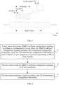
- a radio frame is a unit of radio resources in a time domain.
- a length of a radio frame may be 10 ms, and a radio frame may include 10 subframes.
- the 10 subframes numbered from left to right in sequence, are subframe 0, subframe 1, subframe 2, subframe 3, subframe 4, subframe 5, subframe 6, subframe 7, subframe 8, and subframe 9.
- a length of a subframe may be 1 ms, and a subframe includes two timeslots (slot). Multiple symbols may be transmitted in a subframe.
- a length of each transmitted symbol may be determined according to a cyclic prefix (Cyclic Prefix, CP) length used by the symbol.
- CP Cyclic Prefix
- a CP is a part of a symbol, and is a signal transmitted in a foremost position of the symbol, mainly to reduce impact caused by inter-symbol interference on quality of signal transmission.
- subframes may be classified into multicast-broadcast single-frequency network (Multimedia Broadcast multicast service Single Frequency Network, MBSFN for short) subframes and non-MBSFN subframes.
- MBSFN Multimedia Broadcast multicast service Single Frequency Network
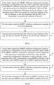
- FIG 2 is a flowchart of a method for sending information according to an embodiment of the present invention.
- the method provided by this embodiment includes: Step 21: A base station determines MBSFN subframe configuration signaling according to a configuration of a cell, where the MBSFN subframe configuration signaling includes CRS transmission configuration information, where the CRS transmission configuration information is used to indicate, to user equipment, a region for transmitting a cell-specific reference signal (Cell-specific Reference Signal, CRS for short) in a time domain.
- CRS Cell-specific Reference Signal
- the CRS transmission configuration information is used to indicate, to the user equipment, the region for transmitting the CRS in the time domain.
- the region for transmitting the CRS in the time domain includes a subframe for transmitting the CRS and the region for transmitting the CRS in the subframe, where the region for transmitting the CRS may be a part of symbols in a subframe, for example, a non-MBSFN region of an MBSFN subframe.
- the MBSFN subframe configuration signaling includes n bits, where the n bits are used to indicate states of the MBSFN subframe configuration signaling, and n is a positive integer; and a particular state in the states of the MBSFN subframe configuration signaling is used to indicate the CRS transmission configuration information.
- a state of the MBSFN subframe configuration signaling is used to provide an indication for the UE.
- the n bits of the MBSFN subframe configuration signaling carry the following parameters: MBSFN subframe configuration (MBSFN subframe configuration), radio frame allocation period (radio frame allocation period), radio frame allocation offset (radio frame Allocation Offset), and subframe allocation (subframe Allocation).
- MBSFN subframe configuration MBSFN subframe configuration
- radio frame allocation period radio frame allocation period
- radio frame allocation offset radio frame Allocation Offset
- subframe allocation subframe Allocation
- a subframe allocation manner is a one-radio-frame (one Frame) allocation manner or a four-radio-frame (four Frames) allocation manner.
- Particular states in the states of the MBSFN subframe configuration signaling are indicated by values of the foregoing parameters in the MBSFN subframe configuration signaling.
- the states of the MBSFN subframe configuration signaling include but are not limited to a state in which a radio frame includes a maximum of six MBSFN subframes.
- a type of the MBSFN subframe configuration is sequence (SEQUENCE).
- the radio frame allocation period is a parameter of an enumeration type, and its value is one of ⁇ n1, n2, n4, n8, n16, n32 ⁇ , where n1/m2/n4/n8/n16/n32 represents that the radio frame period is 1/2/4/8/16/32 radio frames.
- a type of the radio frame allocation offset is integer (INTEGER), and a value range is INTEGER (0-7), namely, integers from 0 to 7, where 0//1/2/3/4/5/6/7 represents that the offset is 0//1/2/3/4/5/6/7 radio frames.
- a type of the subframe allocation is choice (CHOICE), and a value of the subframe allocation is either the one-radio-frame allocation manner or the four-radio-frame allocation manner.
- a type of the one-radio-frame allocation manner is bit string (BIT STRING), and a length thereof is SIZE(6), where bit 0/1/2/3/4/5 represents whether subframe 1/2/3/6/7/8 is an MBSFN subframe, where 1 represents an MBSFN subframe and 0 represents a non-MBSFN subframe.
- a type of the four-radio-frame allocation manner is BIT STRING, and a length thereof is SIZE(24), where bits 0-5, 6-11, 12-17, and 18-23 respectively represent MBSFN subframe configurations in radio frames 0, 1, 2, and 3 in the radio frame period.
- Step 22 The base station sends the MBSFN subframe configuration signaling to the user equipment.
- Step 23 The base station transmits a signal according to the CRS transmission configuration information.
- the signal transmitted by the base station may be a data signal or a control signal or a reference signal or the like, which is not limited herein.
- a base station may use additional signaling to notify user equipment (User Equipment, UE for short) of whether a carrier type of a cell is a conventional carrier type or a new carrier type (New Carrier Type, NCT for short), and further determine a subframe and a symbol for transmitting a CRS.
- UE User Equipment
- NCT New Carrier Type
- the CRS is definitely transmitted in a non-MBSFN subframe, and the CRS is definitely transmitted in a control region of an MBSFN subframe, but in the MBSFN subframe, the CRS is not transmitted in any region except the control region.
- the CRS is replaced with a reduced CRS (Reduced CRS, RCRS for short).
- the CRS is transmitted only in subframe 0 and subframe 5 of each radio frame, and a quantity of CRS ports is only 1.
- the CRS is not transmitted in other subframes of the radio frame.
- a base station uses MBSFN subframe configuration signaling to send CRS transmission configuration information to user equipment to indicate a region for transmitting a CRS in a time domain, and does not use additional signaling to notify the user equipment of the region for transmitting the CRS; without recognizing additional signaling, the user equipment can determine the region for transmitting the CRS, and further determine a configuration of a cell. Therefore, efficiency of determining the configuration of the cell by the user equipment is improved, complexity of determining the configuration of the cell by the UE is reduced, a signaling overhead is saved, and system compatibility is improved.
- the following embodiments respectively describe how CRS transmission configuration information indicates, to user equipment by using a particular state of MBSFN subframe configuration signaling, a region for transmitting a CRS in a time domain. Meanings of all states of the MBSFN subframe configuration signaling are predefined. Optionally, the meanings of all states of the MBSFN configuration signaling are transmitted by a base station to the UE in advance.
- FIG 3 is a flowchart of another method for sending information according to an embodiment of the present invention.
- MBSFN subframe configuration signaling is in a first state.
- the particular state in the states of the MBSFN subframe configuration signaling may be referred to as the first state of the MBSFN subframe configuration signaling.
- the method provided by this embodiment includes: Step 31: A base station determines MBSFN subframe configuration signaling according to a configuration of a cell, where a particular state in states of the MBSFN subframe configuration signaling is used to indicate the CRS transmission configuration information, where the CRS transmission configuration information is used to indicate, to user equipment, that a CRS is transmitted in a first-type subframe of the cell, and indicate, to the user equipment, that the CRS is not transmitted in a second-type subframe of the cell.
- the first-type subframe and the second-type subframe are predefined or are configured by the base station for the user equipment; the first-type subframe is a subframe that is predefined or is configured by the base station for the user equipment and is used to transmit the CRS, and the second-type subframe is a subframe that is predefined or is configured by the base station for the user equipment and is not used to transmit the CRS.
- Step 32 The base station sends the MBSFN subframe configuration signaling to the user equipment.
- Step 33 The base station transmits the CRS in the first-type subframe of the cell, and does not transmit the CRS in the second-type subframe of the cell.
- a reduced CRS (Reduced CRS, RCRS for short) is transmitted or a CRS with one antenna port is transmitted only in subframe 0 and subframe 5 in a radio frame, and the CRS is not transmitted in other subframes. Therefore, the first-type subframe includes subframes 0 and 5, and the second-type subframe includes any subframe except subframes 0 and 5.
- a quantity of CRS ports in the subframe for transmitting the CRS may be equal to 1.
- the quantity of CRS ports in the subframe for transmitting the CRS may also be equal to 2 or 4.
- the first state of the MBSFN subframe configuration signaling may be further used to indicate, to user equipment, and in particular, to user equipment that recognizes an NCT, that a corresponding serving cell of a corresponding carrier does not provide a service for conventional user equipment.
- the conventional user equipment may be user equipment that does not support the NCT.
- the first state of the MBSFN subframe configuration signaling may have the following usage: an MBSFN subframe indicated by the MBSFN subframe configuration signaling is the second-type subframe, and a non-MBSFN subframe is the first-type subframe.
- all states corresponding to the first state are NCT carrier states, that is, the CRS or RCRS is transmitted only in subframe 0 and subframe 5, and the CRS is not transmitted in other subframes.
- the RCRS is a CRS with only one port.
- MBSFN subframe configuration signaling is used to indicate, to user equipment, a region for transmitting a CRS in a time domain, so that whether a carrier type of a cell is an NCT carrier or a conventional carrier can be further determined, without increasing additional signaling. Therefore, efficiency of determining a configuration of the cell by the UE is improved, and complexity of determining the configuration of the cell by the UE is reduced.
- a first state of the MBSFN subframe configuration signaling is configured in the following manner: the first state is one of all states except the following states: (1) a third state, and (2) a state in which a radio frame allocation period is one radio frame and a radio frame allocation offset is not zero.
- the first state may also be used to indicate a configuration of an MBSFN subframe to the UE.
- For the third state of the MBSFN subframe configuration signaling refer to the following description.
- FIG 4 is a flowchart of still another method for sending information according to an embodiment of the present invention.
- MBSFN subframe configuration signaling is in a second state.
- the method provided by this embodiment includes:
- a state that indicates, to the user equipment, that the CRS is transmitted in the non-MBSFN subframe of the cell and in the non-MBSFN region of the MBSFN subframe of the cell may be referred to as a second state of the MBSFN subframe configuration signaling.
- a radio frame of the cell includes at least seven MBSFN subframes, and the particular state in the states of the MBSFN subframe configuration signaling is indicated by a state value of the MBSFN subframe configuration signaling in which a radio frame allocation period is one radio frame and a radio frame allocation offset is not zero.
- the second state of the MBSFN subframe configuration signaling is described by using a reserved or unused state of an MBSFN subframe configuration indicated by a state value of the MBSFN subframe configuration signaling in which the radio frame allocation period is one radio frame, the radio frame allocation offset is not zero, subframe allocation is a one-radio-frame allocation manner and six bits of the one-radio-frame allocation manner are all configured as 1.
- the second state is indicated by a state value of the MBSFN subframe configuration signaling in which the radio frame allocation period is four radio frames, the radio frame allocation offset is greater than or equal to 4, the subframe allocation is a four-radio-frame allocation manner, and 24 bits of the four-radio-frame allocation manner are all configured as 1.
- the second state of the MBSFN subframe configuration signaling may be further indicated by a state value of the MBSFN subframe configuration signaling in which the radio frame allocation period is one radio frame, the radio frame allocation offset is not zero, the subframe allocation is the one-radio-frame allocation manner, and the six bits of the one-radio-frame allocation manner are configured as other values.
- a part of subframes may be predefined as MBSFN subframes, and six bits of the subframe allocation may be used to configure configuration information about whether other subframes are used as MBSFN subframes.
- subframes 2, 3, 4, 6, 7, and 8 are predefined as MBSFN subframes, and the six bits of the one-radio-frame allocation manner are used to indicate whether subframes 0, 1, 5, and 9 are MBSFN subframes.
- the subframe allocation may be further configured according to the four-radio-frame allocation manner. For example, a particular state in the 24 bits of the four-radio-frame allocation manner is used to indicate that more than six MBSFN subframes are included in at least one radio frame in four radio frames, and further, an additional information element may be used for description.
- radio frame allocation offsets offset in total in the MBSFN subframe configuration signaling, where one non-zero radio frame allocation offset offset indentifies N MBSFN subframes and patterns pattern of the subframes.
- a radio frame when a quantity of MBSFN subframes is 7-10, there may be multiple different patterns, where the most important pattern of 7 MBSFN subframes includes 1, 2, 3, 4, 6, 7, and 8, or 1, 2, 3, 6, 7, 8, and 9; the most important pattern of 8 MBSFN subframes is 1, 2, 3, 4, 6, 7, 8, and 9; the most important pattern of 9 MBSFN subframes is 0, 1, 2, 3, 4, 6, 7, 8, and 9, or 1, 2, 3, 4, 5, 6, 7, 8, and 9; and the most important pattern of 10 MBSFN subframes is 0-9.
- MBSFN subframe configuration signaling is used to indicate, to user equipment, a region for transmitting a CRS, and therefore, may indicate whether a state of a carrier is an NCT carrier or a conventional carrier, without increasing additional signaling. Therefore, efficiency of determining a configuration of a cell by the UE is improved, and complexity of determining the configuration of the cell by the UE is reduced.
- the MBSFN subframe configuration signaling is further used to instruct the user equipment to increase a quantity of MBSFN subframes, which increases a service transmission rate in the MBSFN subframes.
- a third state of the MBSFN subframe configuration signaling in particular states in states of the MBSFN subframe configuration signaling, a particular state in the states of the MBSFN subframe configuration signaling that indicates, to the user equipment, that a radio frame includes a maximum of six MBSFN subframes and that a CRS is transmitted in a non-MBSFN subframe of the cell and in a non-MBSFN region of an MBSFN subframe of the cell may be referred to as the third state of the MBSFN subframe configuration signaling.
- the MBSFN subframe configuration signaling When the MBSFN subframe configuration signaling is in the third state, the cell may transmit a service for conventional UE.
- a quantity of CRS ports is 1; or optionally, a quantity of CRS ports is a quantity of CRS ports that is obtained by using a physical broadcast channel (Physical Broadcast Channel, PBCH for short).
- the third state of the MBSFN subframe configuration signaling is configured in the following manner: a radio frame allocation period is one radio frame, a radio frame allocation offset is 0, subframe allocation is configured according to a one-radio-frame allocation manner, and six bits of the one-radio-frame allocation manner are all configured as 1; or a radio frame allocation period is one radio frame, a radio frame allocation offset is 0, subframe allocation is configured according to a four-radio-frame allocation manner, and 24 bits of the four-radio-frame allocation manner are configured as 1.
- the conventional user equipment may be user equipment that does not support the NCT.
- the NCT carrier may be used as a secondary carrier of the conventional user equipment, but the conventional user equipment receives a broadcast channel, a physical downlink control channel (Physical Downlink Control Channel, PDCCH for short), or the like from a primary carrier (non-NCT carrier) of the conventional user equipment. Therefore, a manner is provided: when the conventional user equipment needs to be served, a system parameter corresponding to the third state is configured for the NCT carrier; and when the conventional user equipment does not need to be served, a system parameter corresponding to the NCT carrier is configured, so that the NCT carrier can be used more flexibly and provide a service for the conventional user equipment.
- PDCCH Physical Downlink Control Channel
- Embodiments corresponding to FIG 5, FIG 6A , and FIG 7 mainly describe, from a perspective of a base station side, how to improve efficiency of determining a configuration of a cell by UE, by indicating configuration information of a CP in a subframe to the user equipment.
- FIG 5 is a flowchart of yet another method for sending information according to an embodiment of the present invention.
- the method provided by this embodiment includes: Step 51: A base station determines configuration signaling according to a configuration of a cell, where the configuration signaling includes configuration information of the cell, where the configuration information of the cell includes at least one of the following information: first configuration information of a cyclic prefix CP length or second configuration information of a CP length.
- the first configuration information of the CP length is transmitted by using a system information block type 2 (System Information Block Type 2, SIB 2 for short) and used to indicate, to user equipment, configuration information of a subframe using an extended CP.
- the first configuration information of the CP length is used to indicate, to the user equipment, configuration information of a subframe using an extended CP, for example, indicate, to the user equipment, that in a radio frame, subframes 0, 4, 5, and 9 use a normal CP, and that subframes 1, 2, 3, 6, 7, and 8 use an extended CP.
- the UE can directly and accurately obtain whether a CP actually used by each subframe is an extended CP or a normal CP, without blindly detecting the subframe or obtaining, according to a PDCCH detection result, whether a CP actually used by each subframe is an extended CP or a normal CP.
- the second configuration information of the CP length is used to indicate, to the user equipment, configuration information of a frequency band using an extended CP and/or a frequency band using a normal CP in at least one subframe.
- the base station may indicate, to the user equipment, frequency division multiplexing of an extended CP and a normal CP in a subframe.
- Step 52 The base station sends the configuration signaling to user equipment.
- Step 53 The base station transmits a signal according to the configuration information of the cell.
- the signal transmitted by the base station may be a data signal or a control signal or a reference signal or the like, which is not limited herein.
- a base station indicates, to UE by using MBSFN subframe configuration signaling, which subframes may be MBSFN subframes, the subframes that may be MBSFN subframes do not necessarily transmit an MBMS service.
- the UE can only blindly detect whether the MBSFN subframe uses an extended CP or a normal CP.
- the UE may detect downlink control information (Downlink Control Information, DCI for short) of a control region.
- DCI Downlink Control Information
- the UE detects valid downlink scheduling information for the subframe, it is considered that any region of the subframe except the control region uses a normal CP; otherwise, it is considered that any region of the subframe except the control region uses an extended CP. Then, the UE detects a corresponding channel state information-reference signal (Channel State Information-Reference Signal, CSI-RS for short) and a channel state information interference measurement resource (Channel State Information Interference Measurement Resource, CSI-IMR for short) according to the CP length. Therefore, efficiency of detecting the CSI-RS and the CSI-IMR is affected.
- CSI-RS Channel State Information-Reference Signal
- CSI-IMR Channel State Information Interference Measurement Resource
- a base station incorporates, in configuration information of a cell in configuration signaling, first configuration information of a CP length, for indicating, to user equipment, configuration information of a subframe using an extended CP
- the user equipment can determine, without blindly detecting the MBSFN subframe, whether a symbol in the MBSFN subframe uses an extended CP or a normal CP, and therefore can directly detect a corresponding CSI-RS and CSI-IMR according to the configured CP length. Therefore, efficiency of determining a configuration of the cell by the UE is improved, complexity of determining the configuration of the cell by the UE is reduced, and efficiency of detecting the CSI-RS and CSI-IMR is improved.
- the first configuration information of the CP length, transmitted by using a SIB 2 is used to indicate, to the user equipment, configuration information of a subframe using an extended CP, and may be used in an NCT carrier type.
- the UE can already determine, according to the carrier type, a subframe for transmitting a CRS and that the CRS is transmitted only in subframe 0/5. Therefore, definitely, no CRS is transmitted in subframes 1, 2, 3, 4, 6, 7, 8, and 9.
- the first configuration information of the CP length is indicated by multiplexing MBSFN subframe configuration signaling in the SIB 2, without using additional signaling, so that the UE determines a subframe using an extended CP. Therefore, an advantageous effect of saving a signaling overhead and reducing complexity of the UE may be achieved.
- the UE considers that a CP length used by each symbol in any region of an MBSFN subframe except a control region is the same and is the same in entire system bandwidth.
- a CP length used by each symbol in any region of an MBSFN subframe except a control region is the same and is the same in entire system bandwidth.
- an MBMS service is transmitted in a subframe, even if a part of bandwidth is used for transmission, another part of bandwidth can only be idle and cannot be used for transmitting a non-MBMS service, or another part of bandwidth can use only an extended CP to transmit a non-MBMS service.
- a system capacity is limited by the extended CP, flexibility is limited, and efficiency of using radio resources is also limited.
- the MBMS service may be any service transmitted in the MBSFN subframe, for example, a multimedia broadcast service (Multimedia Broadcast and Multicast Service, MBMS for short) service, or a group communication (group communication) service.
- MBMS Multimedia Broadcast and Multicast Service
- the base station when the base station incorporates, in the configuration information of the cell in the configuration signaling, second configuration information of a CP length, for indicating, to the user equipment, configuration information of a frequency band using an extended CP and/or a frequency band using a normal CP in at least one subframe, frequency division multiplexing may be performed on an MBMS service and a non-MBMS service in a subframe, and a system capacity does not need to be limited by the extended CP. Therefore, resource utilization of a service using a normal CP is improved, flexibility of using radio resources is improved, a capacity of a subframe using an extended CP is increased, and resource utilization of a service using a normal CP is improved.
- the second configuration information of the CP length indicates, to the user equipment, the configuration information of the frequency band using the extended CP and/or the frequency band using the normal CP, efficiency of determining the configuration of the cell by the UE is improved, and complexity of implementation of the UE is reduced.
- FIG 6A is a flowchart of yet another method for sending information according to an embodiment of the present invention.
- This embodiment mainly describes how to perform frequency division multiplexing on an MBMS service and a non-MBMS service in a subframe.
- the method provided by this embodiment includes: Step 61: A base station determines configuration signaling according to a configuration of a cell, where the configuration signaling includes second configuration information of a CP length, and the second configuration information of the CP length is used to indicate, to user equipment, configuration information of a frequency band using an extended CP and a frequency band using a normal CP in at least one subframe, and a location of a guard band not for transmitting a signal in a particular subframe, where the guard band is an intermediate frequency band between a frequency band using an extended CP and a frequency band using a normal CP, and the particular subframe is a subframe using both an extended CP and a normal CP.
- the second configuration information of the CP length may be used to indicate, to the user equipment, at least two of configuration information of the frequency band using the extended CP, configuration information of the frequency band using the normal CP, and configuration information of the guard band.
- the UE may calculate third configuration information according to downlink transmission bandwidth.
- Step 62 The base station sends the configuration signaling to the user equipment.
- Step 63 The base station transmits the signal according to configuration information of the cell.
- an intermediate frequency band between a frequency band using an extended CP and a frequency band using a normal CP is disposed as a guard band not for transmitting a signal. That is, no signal is transmitted in the intermediate frequency band between the frequency band using the extended CP and the frequency band using the normal CP.
- Sizes of sub bandwidth using extended CPs in different subframes are independent, and may be the same, or may be different; likewise, sizes of sub bandwidth using normal CPs in different subframes are independent, and may be the same, or may be different.
- Sizes of guard bands in different subframes are independent.
- a guard band may exist only in a part of subframes or a part of symbols. Because an intermediate frequency band between a frequency band using an extended CP and a frequency band using a normal CP is used as a guard band in a particular subframe, interference between a signal using a normal CP and a signal using an extended CP may be controlled effectively, and a feasible method is provided for efficient use of radio resources.
- the second configuration information of the CP length may indicate a start position of the guard band and a length of the guard band to the user equipment; or may indicate a start position and an end position of the guard band to the user equipment; or may indicate a center position of the guard band and a length of the guard band to the user equipment; or may notify the user equipment that all frequency bands except the frequency band using the extended CP and the frequency band using the normal CP are guard bands, which is not limited herein.
- the base station may use the following signaling manner to notify the UE of locations of the extended CP, the normal CP, and/or the guard band in a frequency domain:
- a transmission frequency band is divided into at least two frequency sub-bands: a frequency band using an extended CP and a frequency band using a normal CP, where CPs used in different frequency sub-bands may be different.
- CPs used by two adjacent frequency sub-bands are different, a guard band is added between the two frequency sub-bands, where the guard band is not used to transmit a signal.
- no guard band is disposed in a last symbol of each timeslot in a particular subframe using both an extended CP and a normal CP.
- no guard band exists in the last symbol of each timeslot in the particular subframe.
- that the base station transmits information to the user equipment according to configuration information of a serving cell includes: the base station transmits the information in the particular subframe to the user equipment according to the configuration information of the serving cell, and does not transmit the signal in the intermediate frequency band between the frequency band using the extended CP and the frequency band using the normal CP in the particular subframe, where the guard band is not disposed in the last symbol of each timeslot in the particular subframe, so that the entire downlink transmission bandwidth may be used for signal transmission.
- the second configuration information of the CP length is further used to indicate, to the user equipment, location information and/or bandwidth information of guard bands in different symbols in the particular subframe.
- bandwidth of a guard band is three subcarriers, but in other symbols, bandwidth of a guard band is five subcarriers.
- a particular subframe uses both an extended CP and a normal CP
- an MBMS service is transmitted in a frequency band of the extended CP of the particular subframe
- a non-MBMS service is transmitted in a frequency band of the normal CP of the particular subframe. Therefore, frequency division multiplexing may be performed on the MBMS service and the non-MBMS service in a particular subframe, and a system capacity does not need to be limited by the extended CP. Therefore, resource utilization of a service using a normal CP is improved, and flexibility of using radio resources is improved.
- a base station uses second configuration information of a CP length to indicate, to UE, that both the extended CP and the normal CP are used in the particular subframe, efficiency of determining a configuration of a cell by the UE is improved, and complexity of determining the configuration of the cell by the UE is reduced. Because an intermediate frequency band between a frequency band using an extended CP and a frequency band using a normal CP is used as a guard band in the particular subframe, interference between a signal using a normal CP and a signal using an extended CP may be controlled effectively, and a feasible method is provided for efficient use of radio resources.
- the configuration signaling sent by the base station to the user equipment may be MBSFN subframe configuration signaling.
- configuration information of the cell in the MBSFN subframe configuration signaling may further include CRS transmission configuration information.
- the CRS transmission configuration information may be indicated by a particular state in states of the MBSFN subframe configuration signaling. For details, refer to descriptions in the embodiments corresponding to FIG 3 and FIG 4 .
- the configuration information of the cell in the configuration signaling sent by the base station to the user equipment may further include first configuration information of the CP length.
- FIG 7 is a flowchart of a method for sending information according to an embodiment of the present invention.
- signaling of configuration information of a serving cell, delivered by a base station to user equipment may be MBSFN subframe configuration signaling, or may be other configuration signaling.
- the method provided by this embodiment includes: Step 71: A base station determines configuration signaling according to a configuration of a cell, where the configuration signaling includes configuration information of the cell, where the configuration information of the cell includes first configuration information of a CP length.
- the first configuration information of the CP length, transmitted by using a SIB 2 is used to indicate, to user equipment, configuration information of a subframe using an extended CP, for example, indicate, to the user equipment, that in a radio frame, subframes 0, 4, 5, and 9 use a normal CP, and that subframes 1, 2, 3, 6, 7, and 8 use an extended CP.
- an information element in the SIB 2 may be used, for example, an MBSFN subframe configuration information element is used.
- MBSFN subframe pattern configuration information in an MBSFN is used to indicate a number of a subframe using an extended CP, or another information element is reused or a new information element is used to indicate a number of a subframe using an extended CP.
- the UE can directly and accurately obtain whether a CP actually used by each subframe is an extended CP or a normal CP, without blindly detecting the subframe or obtaining, according to a PDCCH detection result, whether a CP actually used by each subframe is an extended CP or a normal CP.
- Step 72 The base station sends the configuration signaling to user equipment.
- Step 73 The base station transmits a signal to the user equipment according to configuration information of the cell.
- the configuration signaling sent by the base station to the user equipment may be MBSFN subframe configuration signaling.
- configuration information of the cell in the MBSFN subframe configuration signaling may further include CRS transmission configuration information.
- the CRS transmission configuration information may be indicated by a particular state in states of the MBSFN subframe configuration signaling. For details, refer to descriptions in the embodiments corresponding to FIG 3 and FIG 4 .
- the base station when the configuration information sent by the base station to the user equipment is the MBSFN subframe configuration signaling, the base station indicates, to the user equipment by using the MBSFN subframe configuration signaling, a region for transmitting a CRS in a time domain, and may further determine whether a carrier type of the cell is an NCT carrier or a conventional carrier, without increasing additional signaling. Therefore, efficiency of determining the configuration of the cell by the UE is improved, and complexity of determining the configuration of the cell by the UE is reduced.
- the configuration information of the cell in the configuration signaling sent by the base station to the user equipment may further include second configuration information of the CP length.
- a base station when a base station incorporates, in configuration information of a cell in configuration signaling, first configuration information of a CP length, for indicating, to user equipment, configuration information of a subframe using an extended CP, the user equipment can determine, without blindly detecting the MBSFN subframe, whether a symbol in the MBSFN subframe uses an extended CP or a normal CP, and therefore can directly detect a corresponding CSI-RS and CSI-IMR according to the configured CP length. Therefore, efficiency of determining a configuration of the cell by the UE is improved, complexity of determining the configuration of the cell by the UE is reduced, and efficiency of detecting the CSI-RS and CSI-IMR is improved.
- the first configuration information of the CP length and/or the second configuration information of the CP length may also be indicated by a particular state in the states of the MBSFN subframe configuration signaling.
- the first configuration information of the CP length or the second configuration information of the CP length is indicated by a fourth state of the MBSFN subframe configuration signaling.
- the base station uses a particular state in the states of the MBSFN subframe configuration signaling to indicate, to the user equipment, the configuration information of the subframe using the extended CP, for example, an MBSFN subframe indicated by a state value of the MBSFN subframe configuration signaling is the subframe using the extended CP; or to indicate, to the user equipment, configuration information of a frequency band using an extended CP and/or a frequency band using a normal CP in at least one subframe, for example, an MBSFN subframe indicated by a state value of the MBSFN subframe configuration signaling is a subframe including the frequency band using the extended CP and the frequency band using the normal CP.
- the second configuration information of the CP length indicates, to the user equipment, the configuration information of the frequency band using the extended CP and/or the frequency band using the normal CP, efficiency of determining the configuration of the cell by the UE is improved, and complexity of implementation of the UE is reduced.
- the states of the MBSFN subframe configuration signaling include a first state, a second state, a third state, and a fourth state
- the states of the MBSFN subframe configuration signaling include only a third state and a first state
- the states of the MBSFN subframe configuration signaling include only a third state and a second state
- the states of the MBSFN subframe configuration signaling include only a first state, a second state, and a third state
- the states of the MBSFN subframe configuration signaling include only a third state, a first state, and a fourth state
- the states of the MBSFN subframe configuration signaling include only a third state, a second state, and a fourth state.
- a particular state of the MBSFN subframe configuration signaling is the third state, and/or, the particular state is the first state, and/or, the particular state is the second state, and/or, the particular state is the fourth state.
- the base station may use the states of the MBSFN subframe configuration signaling in combination. For example, combination manner 1: the base station uses only the third state and the first state; combination manner 2: the base station uses only the third state and the second state; combination manner 3: the base station uses the first state, the second state, and the third state in combination; combination manner 4: the base station uses the third state, the first state, and the fourth state in combination; combination manner 5: the base station uses the third state, the second state, and the fourth state in combination.
- All states in the embodiment of the present invention may be all states of MBSFN signaling, or particular states of MBSFN signaling. When all the states are particular states, meanings of some states may be the same as meanings of existing states.
- a state of the MBSFN subframe configuration signaling may also belong to the fourth state when belonging to the first state or the second state or the third state.
- Method embodiments corresponding to FIG 8, FIG 9 , and FIG 10 mainly describe, from a perspective of user equipment, how to improve efficiency of determining a configuration of a cell by the UE, by indicating CRS transmission configuration information in a subframe to the user equipment.
- FIG 8 is a flowchart of a method for receiving information according to an embodiment of the present invention.
- the method provided by this embodiment includes: Step 81: User equipment receives multicast-broadcast single-frequency network MBSFN subframe configuration signaling sent by a base station, where the MBSFN subframe configuration signaling includes cell-specific reference signal CRS transmission configuration information, where the CRS transmission configuration information is used to indicate, to the user equipment, a region for transmitting a CRS in a time domain.
- the CRS transmission configuration information is used to indicate, to the user equipment, the region for transmitting the CRS in the time domain.
- the region for transmitting the CRS in the time domain includes a subframe for transmitting the CRS and the region for transmitting the CRS in the subframe, where the region for transmitting the CRS may be a part of symbols in a subframe, for example, a non-MBSFN region of an MBSFN subframe.
- the MBSFN subframe configuration signaling includes n bits, where the n bits are used to indicate states of the MBSFN subframe configuration signaling, and n is a positive integer; and a particular state in the states of the MBSFN subframe configuration signaling is used to indicate the CRS transmission configuration information.
- a state of the MBSFN subframe configuration signaling is used to provide an indication for the UE.
- the N bits of the MBSFN subframe configuration signaling carry the following parameters: MBSFN subframe configuration (MBSFN subframe configuration), radio frame allocation period (radio frame allocation period), radio frame allocation offset (radio frame Allocation Offset), and subframe allocation (subframe Allocation).
- MBSFN subframe configuration MBSFN subframe configuration
- radio frame allocation period radio frame allocation period
- radio frame allocation offset radio frame Allocation Offset
- subframe allocation subframe Allocation
- the subframe allocation is one of a one-radio-frame (one Frame) allocation manner and a four-radio-frame (four Frames) allocation manner.
- Particular states in the states of the MBSFN subframe configuration signaling are indicated by values of the foregoing parameters in the MBSFN subframe configuration signaling.
- the states of the MBSFN subframe configuration signaling include but are not limited to a state in which a radio frame includes a maximum of six MBSFN subframes.
- a type of the MBSFN subframe configuration is sequence (SEQUENCE).
- the radio frame allocation period is a parameter of an enumeration type, and its value is one of ⁇ n1, n2, n4, n8, n16, n32 ⁇ , where n1/m2/n4/n8/n16/n32 represents that the radio frame period is 1/2/4/8/16/32 radio frames.
- a type of the radio frame allocation offset is integer (INTEGER), and a value range is INTEGER (0-7), namely, integers from 0 to 7, where 0//1/2/3/4/5/6/7 represents that the offset is 0//1/2/3/4/5/6/7 radio frames.
- a type of the subframe allocation is choice (CHOICE), and a value of the subframe allocation is either the one-radio-frame allocation manner or the four-radio-frame allocation manner.
- a type of the one-radio-frame allocation manner is bit string (BIT STRING), and a length thereof is SIZE(6), where bit 0/1/2/3/4/5 represents whether subframe 1/2/3/6/7/8 is an MBSFN subframe, where 1 represents an MBSFN subframe and 0 represents a non-MBSFN subframe.
- a type of the four-radio-frame allocation manner is BIT STRING, and a length thereof is SIZE(24), where bits 0-5, 6-11, 12-17, and 18-23 respectively represent MBSFN subframe configurations in radio frames 0, 1, 2, and 3 in the radio frame period.
- Step 82 The user equipment receives a signal according to the CRS transmission configuration information.
- the received signal may be a data signal or a control signal or a reference signal or the like, which is not limited herein.
- a base station may use additional signaling to notify user equipment (User Equipment, UE for short) of whether a carrier type of a cell is a conventional carrier type or a new carrier type (New Carrier Type, NCT for short), and further determine a subframe and a symbol for transmitting a CRS. Moreover, only UE that recognizes the new carrier type can recognize the additional signaling. Therefore, efficiency of determining a configuration of the cell by the UE is reduced, a signaling overhead is increased, and system compatibility is reduced.
- User Equipment User Equipment
- the CRS is definitely transmitted in a non-MBSFN subframe, and the CRS is definitely transmitted in a control region of an MBSFN subframe, but in the MBSFN subframe, the CRS is not transmitted in any region except the control region.
- the CRS is replaced with a reduced CRS (Reduced CRS, RCRS for short).
- the CRS is transmitted only in subframe 0 and subframe 5 of each radio frame, and a quantity of CRS ports is only 1.
- the CRS is not transmitted in other subframes of the radio frame.
- a base station uses MBSFN subframe configuration signaling to send CRS transmission configuration information to user equipment to indicate a region for transmitting a CRS in a time domain, and does not use additional signaling to notify the user equipment of the region for transmitting the CRS; without recognizing additional signaling, the user equipment can determine the region for transmitting the CRS, and further determine a configuration of a cell. Therefore, efficiency of determining the configuration of the cell by the user equipment is improved, complexity of determining the configuration of the cell by the UE is reduced, a signaling overhead is saved, and system compatibility is improved.
- the following embodiments respectively describe how CRS transmission configuration information indicates, to user equipment by using a particular state of MBSFN subframe configuration signaling, a region for transmitting a CRS in a time domain. Meanings of all states of the MBSFN subframe configuration signaling are predefined. Optionally, the meanings of all states of the MBSFN configuration signaling are transmitted by a base station to the UE in advance.
- FIG 9 is a flowchart of another method for receiving information according to an embodiment of the present invention.
- MBSFN subframe configuration signaling is in a first state.
- the particular state in the states of the MBSFN subframe configuration signaling may be referred to as the first state of the MBSFN subframe configuration signaling.
- the method provided by this embodiment includes: Step 91: User equipment receives MBSFN subframe configuration signaling sent by a base station, where a particular state in states of the MBSFN subframe configuration signaling is used to indicate the CRS transmission configuration information, where the CRS transmission configuration information is used to indicate, to the user equipment, that a CRS is transmitted in a first-type subframe of a cell, and indicate, to the user equipment, that the CRS is not transmitted in a second-type subframe of the cell.
- the first-type subframe and the second-type subframe are predefined or are configured by the base station for the user equipment; the first-type subframe is a subframe that is predefined or is configured by the base station for the user equipment and is used to transmit the CRS, and the second-type subframe is a subframe that is predefined or is configured by the base station for the user equipment and is not used to transmit the CRS.
- Step 92 The user equipment receives the CRS in the first-type subframe of the cell, and does not receive the CRS in the second-type subframe of the cell.
- a reduced CRS Reduced CRS, RCRS for short
- a tracking reference signal Tracking Reference Signal, TRS for short
- the first-type subframe includes subframes 0 and 5
- the second-type subframe includes any subframe except subframes 0 and 5.
- a quantity of CRS ports in the subframe for transmitting the CRS may be equal to 1.
- the quantity of CRS ports in the subframe for transmitting the CRS may also be equal to 2 or 4.
- the first state of the MBSFN subframe configuration signaling may be further used to indicate, to user equipment, and in particular, to user equipment that recognizes an NCT, that a corresponding serving cell of a corresponding carrier does not provide a service for conventional user equipment.
- the conventional user equipment may be user equipment that does not support the NCT.
- the first state of the MBSFN subframe configuration signaling may have the following usage: an MBSFN subframe indicated by the MBSFN subframe configuration signaling is the second-type subframe, and a non-MBSFN subframe is the first-type subframe.
- all states corresponding to the first state are NCT carrier states, that is, the CRS or RCRS is transmitted only in subframe 0 and subframe 5, and the CRS is not transmitted in other subframes.
- the RCRS is a CRS with only one port.
- a base station uses MBSFN subframe configuration signaling to indicate, to user equipment, a region for transmitting a CRS in a time domain, so that whether a carrier type of a cell is an NCT carrier or a conventional carrier can be further determined, without increasing additional signaling. Therefore, efficiency of determining a configuration of the cell by the UE is improved, and complexity of determining the configuration of the cell by the UE is reduced.
- a first state of the MBSFN subframe configuration signaling may be configured in the following manner: the first state may be one of all states except the following states: (1) a third state, and (2) a state in which a radio frame allocation period is one radio frame and a radio frame allocation offset is not zero.
- the first state may also be used to indicate a configuration of an MBSFN subframe to the UE.
- the third state of the MBSFN subframe configuration signaling refer to the following description.
- FIG 10 is a flowchart of still another method for receiving information according to an embodiment of the present invention.
- MBSFN subframe configuration signaling is in a second state.
- the method provided by this embodiment includes:
- a state that indicates, to the user equipment, that the CRS is transmitted in the non-MBSFN subframe of the cell and in the non-MBSFN region of the MBSFN subframe of the cell may be referred to as a second state of the MBSFN subframe configuration signaling.
- a radio frame of the cell includes at least seven MBSFN subframes, and the particular state in the states of the MBSFN subframe configuration signaling is indicated by a state value of the MBSFN subframe configuration signaling in which a radio frame allocation period is one radio frame and a radio frame allocation offset is not zero.
- the second state of the MBSFN subframe configuration signaling may be described by using a reserved or unused state of an MBSFN subframe configuration, for example, indicated by a state value of the MBSFN subframe configuration signaling in which the radio frame allocation period is one radio frame, the radio frame allocation offset is not zero, subframe allocation is a one-radio-frame allocation manner and six bits of the one-radio-frame allocation manner are all configured as 1.
- the second state is indicated by a state value of the MBSFN subframe configuration signaling in which the radio frame allocation period is four radio frames, the radio frame allocation offset is greater than or equal to 4, the subframe allocation is a four-radio-frame allocation manner, and 24 bits of the four-radio-frame allocation manner are all configured as 1.
- the second state of the MBSFN subframe configuration signaling may be further indicated by a state value of the MBSFN subframe configuration signaling in which the radio frame allocation period is one radio frame, the radio frame allocation offset is not zero, the subframe allocation is the one-radio-frame allocation manner, and the six bits of the one-radio-frame allocation manner are configured as other values.
- a part of subframes may be predefined as MBSFN subframes, and six bits of the subframe allocation may be used to configure configuration information about whether other subframes are used as MBSFN subframes.
- subframes 2, 3, 4, 6, 7, and 8 are predefined as MBSFN subframes, and the six bits of the one-radio-frame allocation manner are used to indicate whether subframes 0, 1, 5, and 9 are MBSFN subframes.
- the subframe allocation may be further configured according to the four-radio-frame allocation manner. For example, a particular state in the 24 bits of the four-radio-frame allocation manner is used to indicate that more than six MBSFN subframes are included in at least one radio frame in four radio frames, and further, an additional information element may be used for description.
- radio frame allocation offsets offset in total in the MBSFN subframe configuration signaling, where one non-zero radio frame allocation offset offset indentifies N MBSFN subframes and patterns of the subframes.
- a radio frame when a quantity of MBSFN subframes is 7-10, there may be multiple different patterns, where the most important pattern of 7 MBSFN subframes includes 1, 2, 3, 4, 6, 7, and 8, or 1, 2, 3, 6, 7, 8, and 9; the most important pattern of 8 MBSFN subframes is 1, 2, 3, 4, 6, 7, 8, and 9; the most important pattern of 9 MBSFN subframes is 0, 1, 2, 3, 4, 6, 7, 8, and 9, or 1, 2, 3, 4, 5, 6, 7, 8, and 9; and the most important pattern of 10 MBSFN subframes is 0-9.
- MBSFN subframe configuration signaling is used to indicate, to user equipment, a region for transmitting a CRS, and therefore, may indicate whether a state of a carrier is an NCT carrier or a conventional carrier, without increasing additional signaling. Therefore, efficiency of determining a configuration of a cell by the UE is improved, and complexity of determining the configuration of the cell by the UE is reduced.
- the MBSFN subframe configuration signaling is further used to instruct the user equipment to increase a quantity of MBSFN subframes, which increases a service transmission rate in the MBSFN subframes.
- a third state of the MBSFN subframe configuration signaling in particular states in states of the MBSFN subframe configuration signaling, a particular state in the states of the MBSFN subframe configuration signaling that indicates, to the user equipment, that a radio frame includes a maximum of six MBSFN subframes and that a CRS is transmitted in a non-MBSFN subframe of the cell and in a non-MBSFN region of an MBSFN subframe of the cell may be referred to as the third state of the MBSFN subframe configuration signaling.
- the MBSFN subframe configuration signaling When the MBSFN subframe configuration signaling is in the third state, the cell may transmit a service for conventional UE.
- a quantity of CRS ports is 1; or optionally, a quantity of CRS ports is a quantity of CRS ports that is obtained by using a physical broadcast channel (Physical Broadcast Channel, PBCH for short).
- PBCH Physical Broadcast Channel
- the third state of the MBSFN subframe configuration signaling may be configured in the following manner: a radio frame allocation period is one radio frame, a radio frame allocation offset is 0, subframe allocation is configured according to a one-radio-frame allocation manner, and six bits of the one-radio-frame allocation manner are all configured as 1; or a radio frame allocation period is one radio frame, a radio frame allocation offset is 0, subframe allocation is configured according to a four-radio-frame allocation manner, and 24 bits of the four-radio-frame allocation manner are configured as 1.
- the conventional user equipment may be user equipment that does not support the NCT.
- the NCT carrier may be used as a secondary carrier of the conventional user equipment, but the conventional user equipment receives a broadcast channel, a physical downlink control channel (Physical Downlink Control Channel, PDCCH for short), or the like from a primary carrier (non-NCT carrier) of the conventional user equipment. Therefore, a manner is provided: when the conventional user equipment needs to be served, a system parameter corresponding to the third state is configured for the NCT carrier; and when the conventional user equipment does not need to be served, a system parameter corresponding to the NCT carrier is configured, so that the NCT carrier can be used more flexibly and provide a service for the conventional user equipment.
- PDCCH Physical Downlink Control Channel
- FIG 11 is a flowchart of yet another method for receiving information according to an embodiment of the present invention.
- the method provided by this embodiment includes: Step 111: User equipment receives configuration signaling sent by a base station, where the configuration signaling includes configuration information of a cell, where the configuration information of the cell includes at least one of the following information: first configuration information of a cyclic prefix CP length or second configuration information of a CP length.
- the configuration signaling is determined by the base station according to a configuration of the cell.
- the first configuration information of the CP length is transmitted by using a system information block type 2 (System Information Block Type2, SIB 2 for short) and used to indicate, to the user equipment, configuration information of a subframe using an extended CP.
- the first configuration information of the CP length is used to indicate, to the user equipment, configuration information of a subframe using an extended CP, for example, indicate, to the user equipment, that in a radio frame, subframes 0, 4, 5, and 9 use a normal CP, and that subframes 1, 2, 3, 6, 7, and 8 use an extended CP.
- the UE can directly and accurately obtain whether a CP actually used by each subframe is an extended CP or a normal CP, without blindly detecting the subframe or obtaining, according to a PDCCH detection result, whether a CP actually used by each subframe is an extended CP or a normal CP.
- the second configuration information of the CP length is used to indicate, to the user equipment, configuration information of a frequency band using an extended CP and/or a frequency band using a normal CP in at least one subframe.
- the base station may indicate, to the user equipment, frequency division multiplexing of an extended CP and a normal CP in a subframe.
- Step 112 The user equipment receives a signal according to the configuration information of the cell.
- the signal transmitted by the base station may be a data signal or a control signal or a reference signal or the like, which is not limited herein.
- a base station indicates, to UE by using MBSFN subframe configuration signaling, which subframes may be MBSFN subframes, the subframes that may be MBSFN subframes do not necessarily transmit an MBMS service.
- the UE can only blindly detect whether the MBSFN subframe uses an extended CP or a normal CP.
- the UE may detect downlink control information (Downlink Control Information, DCI for short) of a control region.
- DCI Downlink Control Information
- the UE detects valid downlink scheduling information for the subframe, it is considered that any region of the subframe except the control region uses a normal CP; otherwise, it is considered that any region of the subframe except the control region uses an extended CP. Then, the UE detects a corresponding channel state information-reference signal (Channel State Information-Reference Signal, CSI-RS for short) and a channel state information interference measurement resource (Channel State Information Interference Measurement Resource, CSI-IMR for short) according to the CP length. Therefore, efficiency of detecting the CSI-RS and the CSI-IMR is affected.
- CSI-RS Channel State Information-Reference Signal
- CSI-IMR Channel State Information Interference Measurement Resource
- a base station incorporates, in configuration information of a cell in configuration signaling, first configuration information of a CP length, for indicating, to user equipment, configuration information of a subframe using an extended CP
- the user equipment can determine, without blindly detecting the MBSFN subframe, whether a symbol in the MBSFN subframe uses an extended CP or a normal CP, and therefore can directly detect a corresponding CSI-RS and CSI-IMR according to the configured CP length. Therefore, efficiency of determining a configuration of the cell by the UE is improved, complexity of determining the configuration of the cell by the UE is reduced, and efficiency of detecting the CSI-RS and CSI-IMR is improved.
- the first configuration information of the CP length, transmitted by using a SIB 2 is used to indicate, to the user equipment, configuration information of a subframe using an extended CP, and may be used in an NCT carrier type.
- the UE can already determine, according to the carrier type, a subframe for transmitting a CRS and that the CRS is transmitted only in subframe 0/5. Therefore, definitely, no CRS is transmitted in subframes 1, 2, 3, 4, 6, 7, 8, and 9.
- the first configuration information of the CP length is indicated by multiplexing MBSFN subframe configuration signaling in the SIB 2, without using additional signaling, so that the UE determines a subframe using an extended CP. Therefore, an advantageous effect of saving a signaling overhead and reducing complexity of the UE may be achieved.
- the UE considers that a CP length used by each symbol in any region of an MBSFN subframe except a control region is the same and is the same in entire system bandwidth.
- a CP length used by each symbol in any region of an MBSFN subframe except a control region is the same and is the same in entire system bandwidth.
- an MBMS service is transmitted in a subframe, even if a part of bandwidth is used for transmission, another part of bandwidth can only be idle and cannot be used for transmitting a non-MBMS service, or another part of bandwidth can use only an extended CP to transmit a non-MBMS service.
- a system capacity is limited by the extended CP, flexibility is limited, and efficiency of using radio resources is also limited.
- the MBMS service may be any service transmitted in the MBSFN subframe, for example, a multimedia broadcast service (Multimedia Broadcast and Multicast Service, MBMS for short) service, or a group communication (group communication) service.
- MBMS Multimedia Broadcast and Multicast Service
- the base station when the base station incorporates, in the configuration information of the cell in the configuration signaling, second configuration information of a CP length, for indicating, to the user equipment, configuration information of a frequency band using an extended CP and/or a frequency band using a normal CP in at least one subframe, frequency division multiplexing may be performed on an MBMS service and a non-MBMS service in a subframe, and a system capacity does not need to be limited by the extended CP. Therefore, resource utilization of a service using a normal CP is improved, flexibility of using radio resources is improved, a capacity of a subframe using an extended CP is increased, and resource utilization of a service using a normal CP is improved.
- the second configuration information of the CP length indicates, to the user equipment, the configuration information of the frequency band using the extended CP and/or the frequency band using the normal CP, efficiency of determining the configuration of the cell by the UE is improved, and complexity of implementation of the UE is reduced.
- FIG 12 is a flowchart of yet another method for receiving information according to an embodiment of the present invention.
- This embodiment mainly describes how to perform frequency division multiplexing on an MBMS service and a non-MBMS service in a subframe.
- the method provided by this embodiment includes: Step 121: User equipment receives configuration signaling sent by a base station, where the configuration signaling includes second configuration information of a CP length, and the second configuration information of the CP length is used to indicate, to the user equipment, configuration information of a frequency band using an extended CP and a frequency band using a normal CP in at least one subframe, and a location of a guard band not for transmitting a signal in a particular subframe, where the guard band is an intermediate frequency band between a frequency band using an extended CP and a frequency band using a normal CP, and the particular subframe is a subframe using both an extended CP and a normal CP.
- the second configuration information of the CP length may be used to indicate, to the user equipment, at least two of configuration information of the frequency band using the extended CP, configuration information of the frequency band using the normal CP, and configuration information of the guard band.
- the UE may calculate third configuration information according to downlink transmission bandwidth.
- Step 122 The user equipment receives the signal according to the second configuration information of the CP length, and does not receive the signal in the guard band in the particular subframe.
- an intermediate frequency band between a frequency band using an extended CP and a frequency band using a normal CP is disposed as a guard band not for transmitting a signal. That is, no signal is transmitted in the intermediate frequency band between the frequency band using the extended CP and the frequency band using the normal CP.
- Sizes of sub bandwidth using extended CPs in different subframes are independent, and may be the same, or may be different; likewise, sizes of sub bandwidth using normal CPs in different subframes are independent, and may be the same, or may be different.
- Sizes of guard bands in different subframes are independent.
- a guard band may exist only in a part of subframes or a part of symbols. Because an intermediate frequency band between a frequency band using an extended CP and a frequency band using a normal CP is used as a guard band in a particular subframe, interference between a signal using a normal CP and a signal using an extended CP may be controlled effectively, and a feasible method is provided for efficient use of radio resources.
- the second configuration information of the CP length may indicate a start position of the guard band and a length of the guard band to the user equipment; or may indicate a start position and an end position of the guard band to the user equipment; or may indicate a center position of the guard band and a length of the guard band to the user equipment; or may notify the user equipment that all frequency bands except the frequency band using the extended CP and the frequency band using the normal CP are guard bands, which is not limited herein.
- the base station may use the following signaling manner to notify the UE of locations of the extended CP, the normal CP, and/or the guard band in a frequency domain:
- a transmission frequency band is divided into at least two frequency sub-bands: a frequency band using an extended CP and a frequency band using a normal CP, where CPs used in different frequency sub-bands may be different.
- CPs used by two adjacent frequency sub-bands are different, a guard band is added between the two frequency sub-bands, where the guard band is not used to transmit a signal.
- no guard band is disposed in a last symbol of each timeslot in a particular subframe using both an extended CP and a normal CP.
- no guard band exists in the last symbol of each timeslot in the particular subframe.
- that the base station transmits information to the user equipment according to configuration information of a serving cell includes: the base station transmits the information in the particular subframe to the user equipment according to the configuration information of the serving cell, and does not transmit the signal in the intermediate frequency band between the frequency band using the extended CP and the frequency band using the normal CP in the particular subframe, where the guard band is not disposed in the last symbol of each timeslot in the particular subframe, so that the entire downlink transmission bandwidth may be used for signal transmission.
- the second configuration information of the CP length is further used to indicate, to the user equipment, location information and/or bandwidth information of guard bands in different symbols in the particular subframe.
- bandwidth of a guard band is three subcarriers, but in other symbols, bandwidth of a guard band is five subcarriers.
- a particular subframe uses both an extended CP and a normal CP
- an MBMS service is transmitted in a frequency band of the extended CP of the particular subframe
- a non-MBMS service is transmitted in a frequency band of the normal CP of the particular subframe. Therefore, frequency division multiplexing may be performed on the MBMS service and the non-MBMS service in a particular subframe, and a system capacity does not need to be limited by the extended CP. Therefore, resource utilization of a service using a normal CP is improved, and flexibility of using radio resources is improved.
- a base station uses second configuration information of a CP length to indicate, to UE, that both the extended CP and the normal CP are used in the particular subframe, efficiency of determining a configuration of a cell by the UE is improved, and complexity of determining the configuration of the cell by the UE is reduced. Because an intermediate frequency band between a frequency band using an extended CP and a frequency band using a normal CP is used as a guard band in the particular subframe, interference between a signal using a normal CP and a signal using an extended CP may be controlled effectively, and a feasible method is provided for efficient use of radio resources.
- the configuration signaling received by the user equipment may be MBSFN subframe configuration signaling.
- configuration information of the cell in the MBSFN subframe configuration signaling may further include CRS transmission configuration information.
- the CRS transmission configuration information may be indicated by a particular state in states of the MBSFN subframe configuration signaling. For details, refer to descriptions in the embodiments corresponding to FIG 9 and FIG 10 .
- the configuration information of the cell in the configuration signaling sent by the base station to the user equipment may further include first configuration information of the CP length.
- FIG 13 is a flowchart of a method for receiving information according to an embodiment of the present invention.
- signaling of configuration information of a serving cell, delivered by a base station to user equipment is not limited to MBSFN subframe configuration signaling, and may be other configuration signaling.
- the method provided by this embodiment includes: Step 131: User equipment receives configuration signaling sent by a base station, where the configuration signaling includes configuration information of a cell, where the configuration information of the cell includes first configuration information of a CP length.
- the first configuration information of the CP length, transmitted by using a SIB 2 is used to indicate, to the user equipment, configuration information of a subframe using an extended CP, for example, indicate, to the user equipment, that in a radio frame, subframes 0, 4, 5, and 9 use a normal CP, and that subframes 1, 2, 3, 6, 7, and 8 use an extended CP.
- an information element in the SIB 2 may be used, for example, an MBSFN subframe configuration information element is used.
- MBSFN subframe pattern configuration information in an MBSFN is used to indicate a number of a subframe using an extended CP, or another information element is reused or a new information element is used to indicate a number of a subframe using an extended CP.
- the UE can directly and accurately obtain whether a CP actually used by each subframe is an extended CP or a normal CP, without blindly detecting the subframe or obtaining, according to a PDCCH detection result, whether a CP actually used by each subframe is an extended CP or a normal CP.
- Step 132 The user equipment receives a signal according to the configuration information of the cell.
- the configuration signaling received by the user equipment may be MBSFN subframe configuration signaling.
- configuration information of the cell in the MBSFN subframe configuration signaling may further include CRS transmission configuration information.
- the CRS transmission configuration information may be indicated by a particular state in states of the MBSFN subframe configuration signaling. For details, refer to descriptions in the embodiments corresponding to FIG 3 and FIG 4 .
- the base station when the configuration information sent by the base station to the user equipment is the MBSFN subframe configuration signaling, the base station indicates, to the user equipment by using the MBSFN subframe configuration signaling, a region for transmitting a CRS in a time domain, and may further determine whether a carrier type of the cell is an NCT carrier or a conventional carrier, without increasing additional signaling. Therefore, efficiency of determining a configuration of the cell by the UE is improved, and complexity of determining the configuration of the cell by the UE is reduced.
- the configuration information of the cell in the configuration signaling received by the user equipment may further include second configuration information of the CP length.
- a base station when a base station incorporates, in configuration information of a cell in configuration signaling, first configuration information of a CP length, for indicating, to user equipment, configuration information of a subframe using an extended CP, the user equipment can determine, without blindly detecting the MBSFN subframe, whether a symbol in the MBSFN subframe uses an extended CP or a normal CP, and therefore can directly detect a corresponding CSI-RS and CSI-IMR according to the configured CP length. Therefore, efficiency of determining a configuration of the cell by the UE is improved, complexity of determining the configuration of the cell by the UE is reduced, and efficiency of detecting the CSI-RS and CSI-IMR is improved.
- the first configuration information of the CP length and/or the second configuration information of the CP length may also be indicated by a particular state in the states of the MBSFN subframe configuration signaling.
- the first configuration information of the CP length or the second configuration information of the CP length is indicated by a fourth state of the MBSFN subframe configuration signaling.
- the base station uses a particular state in the states of the MBSFN subframe configuration signaling to indicate, to the user equipment, the configuration information of the subframe using the extended CP, for example, an MBSFN subframe indicated by a state value of the MBSFN subframe configuration signaling is the subframe using the extended CP; or to indicate, to the user equipment, configuration information of a frequency band using an extended CP and/or a frequency band using a normal CP in at least one subframe, for example, an MBSFN subframe indicated by a state value of the MBSFN subframe configuration signaling is a subframe including the frequency band using the extended CP and the frequency band using the normal CP.
- the second configuration information of the CP length indicates, to the user equipment, the configuration information of the frequency band using the extended CP and/or the frequency band using the normal CP, efficiency of determining the configuration of the cell by the UE is improved, and complexity of implementation of the UE is reduced.
- the states of the MBSFN subframe configuration signaling include a first state, a second state, a third state, and a fourth state
- the states of the MBSFN subframe configuration signaling include only a third state and a first state
- the states of the MBSFN subframe configuration signaling include only a third state and a second state
- the states of the MBSFN subframe configuration signaling include only a first state, a second state, and a third state
- the states of the MBSFN subframe configuration signaling include only a third state, a first state, and a fourth state
- the states of the MBSFN subframe configuration signaling include only a third state, a second state, and a fourth state.
- a particular state of the MBSFN subframe configuration signaling is the third state, and/or, the particular state is the first state, and/or, the particular state is the second state, and/or, the particular state is the fourth state.
- the base station may use the states of the MBSFN subframe configuration signaling in combination. For example, combination manner 1: the base station uses only the third state and the first state; combination manner 2: the base station uses only the third state and the second state; combination manner 3: the base station uses the first state, the second state, and the third state in combination; combination manner 4: the base station uses the third state, the first state, and the fourth state in combination; combination manner 5: the base station uses the third state, the second state, and the fourth state in combination.
- All states in the embodiment of the present invention may be all states of MBSFN signaling, or particular states of MBSFN signaling. When all the states are particular states, meanings of some states may be the same as meanings of existing states.
- a state of the MBSFN subframe configuration signaling may also belong to the fourth state when belonging to the first state or the second state or the third state.
- FIG 14 is a schematic structural diagram of a base station according to an embodiment of the present invention.
- the base station provided by this embodiment includes a processor 141 and a transceiver 142.
- the processor 141 is configured to determine multicast-broadcast single-frequency network MBSFN subframe configuration signaling according to a configuration of a cell, where the MBSFN subframe configuration signaling includes cell-specific reference signal CRS transmission configuration information, where the CRS transmission configuration information is used to indicate, to user equipment, a region for transmitting the CRS in a time domain.
- the region for transmitting the CRS in the time domain includes a subframe for transmitting the CRS and the region for transmitting the CRS in the subframe, where the region for transmitting the CRS may be a part of symbols in a subframe, for example, a non-MBSFN region of an MBSFN subframe.
- the transceiver 142 is configured to send the MBSFN subframe configuration signaling to the user equipment.
- the transceiver 142 is further configured to transmit a signal according to the CRS transmission configuration information.
- the MBSFN subframe configuration signaling includes n bits, where the n bits are used to indicate states of the MBSFN subframe configuration signaling, and n is a positive integer; and a particular state in the states of the MBSFN subframe configuration signaling is used to indicate the CRS transmission configuration information.
- a state of the MBSFN subframe configuration signaling is used to provide an indication for the UE.
- the N bits of the MBSFN subframe configuration signaling carry the following parameters: MBSFN subframe configuration (MBSFN subframe configuration), radio frame allocation period (radio frame allocation period), radio frame allocation offset (radio frame Allocation Offset), and subframe allocation (subframe Allocation).
- the subframe allocation is one of a one-radio-frame (one Frame) allocation manner and a four-radio-frame (four Frames) allocation manner.
- Particular states in the states of the MBSFN subframe configuration signaling are indicated by values of the foregoing parameters in the MBSFN subframe configuration signaling.
- the states of the MBSFN subframe configuration signaling include but are not limited to a state in which a radio frame includes a maximum of six MBSFN subframes.
- a type of the MBSFN subframe configuration is sequence (SEQUENCE).
- the radio frame allocation period is a parameter of an enumeration type, and its value is one of ⁇ n1, n2, n4, n8, n16, n32 ⁇ , where n1/m2/n4/n8/n16/n32 represents that the radio frame period is 1/2/4/8/16/32 radio frames.
- a type of the radio frame allocation offset is integer (INTEGER), and a value range is INTEGER (0-7), namely, integers from 0 to 7, where 0//1/2/3/4/5/6/7 represents that the offset is 0//1/2/3/4/5/6/7 radio frames.
- a type of the subframe allocation is choice (CHOICE), and a value of the subframe allocation is either the one-radio-frame allocation manner or the four-radio-frame allocation manner.
- a type of the one-radio-frame allocation manner is bit string (BIT STRING), and a length thereof is SIZE(6), where bit 0/1/2/3/4/5 represents whether subframe 1/2/3/6/7/8 is an MBSFN subframe, where 1 represents an MBSFN subframe and 0 represents a non-MBSFN subframe.
- a type of the four-radio-frame allocation manner is BIT STRING, and a length thereof is SIZE(24), where bits 0-5, 6-11, 12-17, and 18-23 respectively represent MBSFN subframe configurations in radio frames 0, 1, 2, and 3 in the radio frame period.
- a base station uses MBSFN subframe configuration signaling to send CRS transmission configuration information to user equipment to indicate a region for transmitting a CRS in a time domain, and does not use additional signaling to notify the user equipment of the region for transmitting the CRS; without recognizing additional signaling, the user equipment can determine the region for transmitting the CRS, and further determine a configuration of a cell. Therefore, efficiency of determining the configuration of the cell by the user equipment is improved, complexity of determining the configuration of the cell by the UE is reduced, a signaling overhead is saved, and system compatibility is improved.
- the transceiver is further configured to transmit the CRS in a first-type subframe of the cell, and skip transmitting the CRS in a second-type subframe of the cell; and a particular state in the states of the MBSFN subframe configuration signaling is used to indicate, to the user equipment, that the CRS is transmitted in the first-type subframe of the cell, and indicate, to the user equipment, that the CRS is not transmitted in the second-type subframe of the cell, where the first-type subframe and the second-type subframe are predefined or configured by the base station for the user equipment.
- the particular state in the states of the MBSFN subframe configuration signaling that indicates, to the user equipment, that the CRS is transmitted in the first-type subframe of the cell, and indicates, to the user equipment, that the CRS is not transmitted in the second-type subframe of the cell, may be referred to as a first state of the MBSFN subframe configuration signaling.
- a reduced CRS Reduced CRS, RCRS for short
- a tracking reference signal Tracking Reference Signal, TRS for short
- a CRS with one antenna port is transmitted only in subframe 0 and subframe 5 in a radio frame, and the CRS is not transmitted in other subframes. Therefore, the first-type subframe includes subframes 0 and 5, and the second-type subframe includes any subframe except subframes 0 and 5.
- a quantity of CRS ports in the subframe for transmitting the CRS may be equal to 1.
- the quantity of CRS ports in the subframe for transmitting the CRS may also be equal to 2 or 4.
- the first state of the MBSFN subframe configuration signaling may be further used to indicate, to user equipment, and in particular, to user equipment that recognizes an NCT, that a corresponding serving cell of a corresponding carrier does not provide a service for conventional user equipment.
- the conventional user equipment may be user equipment that does not support the NCT.
- the first state of the MBSFN subframe configuration signaling may have the following usage: an MBSFN subframe indicated by the MBSFN subframe configuration signaling is the second-type subframe, and a non-MBSFN subframe is the first-type subframe.
- all states corresponding to the first state are NCT carrier states, that is, the CRS or RCRS is transmitted only in subframe 0 and subframe 5, and the CRS is not transmitted in other subframes.
- the RCRS is a CRS with only one port.
- the first state of the MBSFN subframe configuration signaling may be configured in the following manner: the first state may be one of all states except the following states: (1) a third state, and (2) a state in which the radio frame allocation period is one radio frame and the radio frame allocation offset is not zero.
- the first state may also be used to indicate a configuration of an MBSFN subframe to the UE.
- the third state of the MBSFN subframe configuration signaling refer to the following description.
- the transceiver is further configured to transmit the CRS in a non-MBSFN subframe of the cell and in a non-MBSFN region of an MBSFN subframe of the cell, and a particular state in the states of the MBSFN subframe configuration signaling is used to indicate, to the user equipment, that the CRS is transmitted in the non-MBSFN subframe of the cell and in the non-MBSFN region of the MBSFN subframe of the cell.
- the particular state in the states of the MBSFN subframe configuration signaling is indicated by a state value of the MBSFN subframe configuration signaling in which the radio frame allocation period is one radio frame and the radio frame allocation offset is not zero.
- the state that indicates, to the user equipment, that the CRS is transmitted in the non-MBSFN subframe of the cell and in the non-MBSFN region of the MBSFN subframe of the cell may be referred to as a second state of the MBSFN subframe configuration signaling.
- a radio frame of the cell includes at least seven MBSFN subframes, and the particular state in the states of the MBSFN subframe configuration signaling is indicated by a state of the MBSFN subframe configuration signaling in which the radio frame allocation period is one radio frame and the radio frame allocation offset is not zero.
- the second state of the MBSFN subframe configuration signaling may be described by using a reserved or unused state of an MBSFN subframe configuration, for example, indicated by a state value of the MBSFN subframe configuration signaling in which the radio frame allocation period is one radio frame, the radio frame allocation offset is not zero, the subframe allocation is the one-radio-frame allocation manner and the six bits of the one-radio-frame allocation manner are all configured as 1.
- the second state is indicated by a state value of the MBSFN subframe configuration signaling in which the radio frame allocation period is four radio frames, the radio frame allocation offset is greater than or equal to 4, the subframe allocation is the four-radio-frame allocation manner, and the 24 bits of the four-radio-frame allocation manner are all configured as 1.
- the second state of the MBSFN subframe configuration signaling may be further indicated by a state value of the MBSFN subframe configuration signaling in which the radio frame allocation period is one radio frame, the radio frame allocation offset is not zero, the subframe allocation is the one-radio-frame allocation manner, and the six bits of the one-radio-frame allocation manner are configured as other values.
- a part of subframes may be predefined as MBSFN subframes, and six bits of the subframe allocation may be used to configure configuration information about whether other subframes are used as MBSFN subframes.
- subframes 2, 3, 4, 6, 7, and 8 are predefined as MBSFN subframes, and the six bits of the one-radio-frame allocation manner are used to indicate whether subframes 0, 1, 5, and 9 are MBSFN subframes.
- the subframe allocation may be further configured according to the four-radio-frame allocation manner. For example, a particular state in the 24 bits of the four-radio-frame allocation manner is used to indicate that more than six MBSFN subframes are included in at least one radio frame in four radio frames, and further, an additional information element may be used for description.
- radio frame allocation offsets offset in total in the MBSFN subframe configuration signaling, where one non-zero radio frame allocation offset offset indentifies N MBSFN subframes and patterns of the subframes.
- a radio frame when a quantity of MBSFN subframes is 7-10, there may be multiple different patterns, where the most important pattern of 7 MBSFN subframes includes 1, 2, 3, 4, 6, 7, and 8, or 1, 2, 3, 6, 7, 8, and 9; the most important pattern of 8 MBSFN subframes is 1, 2, 3, 4, 6, 7, 8, and 9; the most important pattern of 9 MBSFN subframes is 0, 1, 2, 3, 4, 6, 7, 8, and 9, or 1, 2, 3, 4, 5, 6, 7, 8, and 9; and the most important pattern of 10 MBSFN subframes is 0-9.
- a particular state in the states of the MBSFN subframe configuration signaling that indicates, to the user equipment, that a radio frame includes a maximum of six MBSFN subframes and that the CRS is transmitted in the non-MBSFN subframe of the cell and in the non-MBSFN region of the MBSFN subframe of the cell may be referred to as the third state of the MBSFN subframe configuration signaling.
- the MBSFN subframe configuration signaling is in the third state, the cell may transmit a service for conventional UE.
- the quantity of CRS ports is 1; or optionally, the quantity of CRS ports is a quantity of CRS ports that is obtained by using a physical broadcast channel (Physical Broadcast Channel, PBCH for short).
- the third state of the MBSFN subframe configuration signaling may be configured in the following manner: the radio frame allocation period is one radio frame, the radio frame allocation offset is 0, the subframe allocation is configured according to the one-radio-frame allocation manner, and the six bits of the one-radio-frame allocation manner are all configured as 1; or the radio frame allocation period is one radio frame, the radio frame allocation offset is 0, the subframe allocation is configured according to the four-radio-frame allocation manner, and the 24 bits of the four-radio-frame allocation manner are configured as 1.
- the conventional user equipment may be user equipment that does not support the NCT.
- the NCT carrier may be used as a secondary carrier of the conventional user equipment, but the conventional user equipment receives a broadcast channel, a physical downlink control channel (Physical Downlink Control Channel, PDCCH for short), or the like from a primary carrier (non-NCT carrier) of the conventional user equipment. Therefore, a manner is provided: when the conventional user equipment needs to be served, a system parameter corresponding to the third state is configured for the NCT carrier; and when the conventional user equipment does not need to be served, a system parameter corresponding to the NCT carrier is configured, so that the NCT carrier can be used more flexibly and provide a service for the conventional user equipment.
- PDCCH Physical Downlink Control Channel
- FIG 15 is a schematic structural diagram of another base station according to an embodiment of the present invention.
- the base station provided by this embodiment includes a processor 151 and a transceiver 152.
- the processor 151 is configured to determine configuration signaling according to a configuration of a cell, where the configuration signaling includes configuration information of the cell, where the configuration information of the cell includes at least one of the following information: first configuration information of a cyclic prefix CP length or second configuration information of a CP length.
- the first configuration information of the CP length is transmitted by using a system information block type 2 (System Information Block Type2, SIB 2 for short) and used to indicate, to user equipment, configuration information of a subframe using an extended CP.
- the first configuration information of the CP length is used to indicate, to the user equipment, configuration information of a subframe using an extended CP, for example, indicate, to the user equipment, that in a radio frame, subframes 0, 4, 5, and 9 use a normal CP, and that subframes 1, 2, 3, 6, 7, and 8 use an extended CP.
- the UE can directly and accurately obtain whether a CP actually used by each subframe is an extended CP or a normal CP, without blindly detecting the subframe or obtaining, according to a PDCCH detection result, whether a CP actually used by each subframe is an extended CP or a normal CP.
- the first configuration information of the CP length indicates, to the user equipment, that in a radio frame, subframes 0, 4, 5, and 9 use a normal CP, and that subframes 1, 2, 3, 6, 7, and 8 use an extended CP.
- an information element in the SIB 2 may be used, for example, an MBSFN subframe configuration information element is used.
- MBSFN subframe pattern configuration information in an MBSFN is used to indicate a number of a subframe using an extended CP, or another information element is reused or a new information element is used to indicate a number of a subframe using an extended CP. Therefore, the UE can directly and accurately obtain whether a CP actually used by each subframe is an extended CP or a normal CP, without blindly detecting the subframe or obtaining, according to a PDCCH detection result, whether a CP actually used by each subframe is an extended CP or a normal CP.
- the second configuration information of the CP length is used to indicate, to the user equipment, configuration information of a frequency band using an extended CP and/or a frequency band using a normal CP in at least one subframe.
- the base station may indicate, to the user equipment, frequency division multiplexing of an extended CP and a normal CP in a subframe.
- the transceiver 152 is configured to send the configuration signaling to the user equipment.
- the transceiver 152 is further configured to transmit a signal according to the configuration information of the cell.
- a base station when a base station incorporates, in configuration information of a cell in configuration signaling, first configuration information of a CP length, for indicating, to user equipment, configuration information of a subframe using an extended CP, the user equipment can determine, without blindly detecting the MBSFN subframe, whether a symbol in the MBSFN subframe uses an extended CP or a normal CP, and therefore can directly detect a corresponding CSI-RS and CSI-IMR according to the configured CP length. Therefore, efficiency of determining a configuration of the cell by the UE is improved, complexity of determining the configuration of the cell by the UE is reduced, and efficiency of detecting the CSI-RS and CSI-IMR is improved.
- frequency division multiplexing may be performed on an MBMS service and a non-MBMS service in a subframe, and a system capacity does not need to be limited by the extended CP. Therefore, resource utilization of a service using a normal CP is improved, flexibility of using radio resources is improved, a capacity of a subframe using an extended CP is increased, and resource utilization of a service using a normal CP is improved.
- the second configuration information of the CP length indicates, to the user equipment, the configuration information of the frequency band using the extended CP and/or the frequency band using the normal CP, efficiency of determining the configuration of the cell by the UE is improved, and complexity of implementation of the UE is reduced.
- an intermediate frequency band between a frequency band using an extended CP and a frequency band using a normal CP is disposed as a guard band not for transmitting a signal. That is, no signal is transmitted in the intermediate frequency band between the frequency band using the extended CP and the frequency band using the normal CP.
- Sizes of sub bandwidth using extended CPs in different subframes are independent, and may be the same, or may be different; likewise, sizes of sub bandwidth using normal CPs in different subframes are independent, and may be the same, or may be different.
- Sizes of guard bands in different subframes are independent.
- a guard band may exist only in a part of subframes or a part of symbols. Because an intermediate frequency band between a frequency band using an extended CP and a frequency band using a normal CP is used as a guard band in a particular subframe, interference between a signal using a normal CP and a signal using an extended CP may be controlled effectively, and a feasible method is provided for efficient use of radio resources.
- the transceiver is further configured to transmit the signal according to the second configuration information of the CP length and skip transmitting the signal in the guard band in the particular subframe, where the second configuration information of the CP length is further used to indicate, to the user equipment, a location of the guard band not for transmitting the signal in the particular subframe, where the guard band is an intermediate frequency band between a frequency band using an extended CP and a frequency band using a normal CP, and the particular subframe is a subframe using both an extended CP and a normal CP.
- the transceiver is further configured to transmit the signal in a last symbol of each timeslot in the particular subframe, where the guard band is not disposed in the last symbol of each timeslot in the particular subframe. As shown in FIG 6C , no guard band exists in the last symbol of each timeslot in the particular subframe.
- the second configuration information of the CP length is further used to indicate, to the user equipment, location information and/or bandwidth information of guard bands in different symbols in the particular subframe.
- bandwidth of a guard band is three subcarriers, but in other symbols, bandwidth of a guard band is five subcarriers.
- the second configuration information of the CP length may indicate a start position of the guard band and a length of the guard band to the user equipment; or may indicate a start position and an end position of the guard band to the user equipment; or may indicate a center position of the guard band and a length of the guard band to the user equipment; or may notify the user equipment that all frequency bands except the frequency band using the extended CP and the frequency band using the normal CP are guard bands, which is not limited herein.
- a transmission frequency band is divided into at least two frequency sub-bands: a frequency band using an extended CP and a frequency band using a normal CP, where CPs used in different frequency sub-bands may be different.
- CPs used by two adjacent frequency sub-bands are different, a guard band is added between the two frequency sub-bands, where the guard band is not used to transmit a signal.
- the configuration signaling is multicast-broadcast single-frequency network MBSFN subframe configuration signaling.
- the configuration information of the cell further includes cell-specific reference signal CRS transmission configuration information, where the CRS transmission configuration information is used to indicate, to the user equipment, a region for transmitting a CRS in a time domain.
- the CRS transmission configuration information may be indicated by a particular state in states of the MBSFN subframe configuration signaling.
- FIG 16 is a schematic structural diagram of user equipment according to an embodiment of the present invention. As shown in FIG 16 , the equipment provided by this embodiment includes a transceiver 161 and a processor 162.
- the transceiver 161 is configured to receive multicast-broadcast single-frequency network MBSFN subframe configuration signaling sent by a base station, where the MBSFN subframe configuration signaling includes cell-specific reference signal CRS transmission configuration information, where the CRS transmission configuration information is used to indicate, to the user equipment, a region for transmitting a CRS in a time domain.
- the processor 162 is configured to parse the MBSFN subframe configuration signaling.
- the transceiver 161 is further configured to receive a signal according to the CRS transmission configuration information.
- the region for transmitting the CRS in the time domain includes a subframe for transmitting the CRS and the region for transmitting the CRS in the subframe, where the region for transmitting the CRS may be a part of symbols in a subframe, for example, a non-MBSFN region of an MBSFN subframe.
- the MBSFN subframe configuration signaling includes n bits, where the n bits are used to indicate states of the MBSFN subframe configuration signaling, and n is a positive integer; and a particular state in the states of the MBSFN subframe configuration signaling is used to indicate the CRS transmission configuration information.
- a state of the MBSFN subframe configuration signaling is used to provide an indication for the UE.
- the N bits of the MBSFN subframe configuration signaling carry the following parameters: MBSFN subframe configuration (MBSFN subframe configuration), radio frame allocation period (radio frame allocation period), radio frame allocation offset (radio frame Allocation Offset), and subframe allocation (subframe Allocation).
- the subframe allocation is one of a one-radio-frame (one Frame) allocation manner and a four-radio-frame (four Frames) allocation manner.
- Particular states in the states of the MBSFN subframe configuration signaling are indicated by values of the foregoing parameters in the MBSFN subframe configuration signaling.
- the states of the MBSFN subframe configuration signaling include but are not limited to a state in which a radio frame includes a maximum of six MBSFN subframes.
- a type of the MBSFN subframe configuration is sequence (SEQUENCE).
- the radio frame allocation period is a parameter of an enumeration type, and its value is one of ⁇ n1, n2, n4, n8, n16, n32 ⁇ , where n1/m2/n4/n8/n16/n32 represents that the radio frame period is 1/2/4/8/16/32 radio frames.
- a type of the radio frame allocation offset is integer (INTEGER), and a value range is INTEGER (0-7), namely, integers from 0 to 7, where 0//1/2/3/4/5/6/7 represents that the offset is 0//1/2/3/4/5/6/7 radio frames.
- a type of the subframe allocation is choice (CHOICE), and a value of the subframe allocation is either the one-radio-frame allocation manner or the four-radio-frame allocation manner.
- a type of the one-radio-frame allocation manner is bit string (BIT STRING), and a length thereof is SIZE(6), where bit 0/1/2/3/4/5 represents whether subframe 1/2/3/6/7/8 is an MBSFN subframe, where 1 represents an MBSFN subframe and 0 represents a non-MBSFN subframe.
- a type of the four-radio-frame allocation manner is BIT STRING, and a length thereof is SIZE(24), where bits 0-5, 6-11, 12-17, and 18-23 respectively represent MBSFN subframe configurations in radio frames 0, 1, 2, and 3 in the radio frame period.
- a base station uses MBSFN subframe configuration signaling to send CRS transmission configuration information to user equipment to indicate a region for transmitting a CRS in a time domain, and does not use additional signaling to notify the user equipment of the region for transmitting the CRS; without recognizing additional signaling, the user equipment can determine the region for transmitting the CRS, and further determine a configuration of a cell. Therefore, efficiency of determining the configuration of the cell by the user equipment is improved, complexity of determining the configuration of the cell by the UE is reduced, a signaling overhead is saved, and system compatibility is improved.
- the transceiver is further configured to receive the CRS in a first-type subframe of the cell, and skip receiving the CRS in a second-type subframe of the cell; and a particular state in the states of the MBSFN subframe configuration signaling is used to indicate, to the user equipment, that the CRS is transmitted in the first-type subframe of the cell, and indicate, to the user equipment, that the CRS is not transmitted in the second-type subframe of the cell, where the first-type subframe and the second-type subframe are predefined or configured by the base station for the user equipment.
- the state of the MBSFN subframe configuration signaling that indicates, to the user equipment, that the CRS is transmitted in the first-type subframe of the cell, and indicates, to the user equipment, that the CRS is not transmitted in the second-type subframe of the cell, may be referred to as a first state of the MBSFN subframe configuration signaling.
- a reduced CRS Reduced CRS, RCRS for short
- a tracking reference signal Tracking Reference Signal, TRS for short
- a CRS with one antenna port is transmitted only in subframe 0 and subframe 5 in a radio frame, and the CRS is not transmitted in other subframes. Therefore, the first-type subframe includes subframes 0 and 5, and the second-type subframe includes any subframe except subframes 0 and 5.
- a quantity of CRS ports in the subframe for transmitting the CRS may be equal to 1.
- the quantity of CRS ports in the subframe for transmitting the CRS may also be equal to 2 or 4.
- the first state of the MBSFN subframe configuration signaling may be further used to indicate, to user equipment, and in particular, to user equipment that recognizes an NCT, that a corresponding serving cell of a corresponding carrier does not provide a service for conventional user equipment.
- the conventional user equipment may be user equipment that does not support the NCT.
- the first state of the MBSFN subframe configuration signaling may have the following usage: an MBSFN subframe indicated by the MBSFN subframe configuration signaling is the second-type subframe, and a non-MBSFN subframe is the first-type subframe.
- all states corresponding to the first state are NCT carrier states, that is, the CRS or RCRS is transmitted only in subframe 0 and subframe 5, and the CRS is not transmitted in other subframes.
- the RCRS is a CRS with only one port.
- the first state of the MBSFN subframe configuration signaling may be configured in the following manner: the first state may be one of all states except the following states: (1) a third state, and (2) a state in which the radio frame allocation period is one radio frame and the radio frame allocation offset is not zero.
- the first state may also be used to indicate a configuration of an MBSFN subframe to the UE.
- the third state of the MBSFN subframe configuration signaling refer to the following description.
- MBSFN subframe configuration signaling is used to indicate, to user equipment, a region for transmitting a CRS in a time domain, so that whether a carrier type of a cell is an NCT carrier or a conventional carrier can be further determined, without increasing additional signaling. Therefore, efficiency of determining a configuration of the cell by the UE is improved, and complexity of determining the configuration of the cell by the UE is reduced.
- the transceiver is further configured to receive the CRS in a non-MBSFN subframe of the cell and in a non-MBSFN region of an MBSFN subframe of the cell; and a particular state in the states of the MBSFN subframe configuration signaling is used to indicate, to the user equipment, that the CRS is transmitted in the non-MBSFN subframe of the cell and in the non-MBSFN region of the MBSFN subframe of the cell.
- the particular state in the states of the MBSFN subframe configuration signaling is indicated by a state of the MBSFN subframe configuration signaling in which the radio frame allocation period is one radio frame and the radio frame allocation offset is not zero.
- the state that indicates, to the user equipment, that the CRS is transmitted in the non-MBSFN subframe of the cell and in the non-MBSFN region of the MBSFN subframe of the cell may be referred to as a second state of the MBSFN subframe configuration signaling.
- a radio frame of the cell includes at least seven MBSFN subframes, and the particular state in the states of the MBSFN subframe configuration signaling is indicated by a state value of the MBSFN subframe configuration signaling in which the radio frame allocation period is one radio frame and the radio frame allocation offset is not zero.
- the second state of the MBSFN subframe configuration signaling may be described by using a reserved or unused state of an MBSFN subframe configuration, for example, indicated by a state value of the MBSFN subframe configuration signaling in which the radio frame allocation period is one radio frame, the radio frame allocation offset is not zero, the subframe allocation is the one-radio-frame allocation manner and the six bits of the one-radio-frame allocation manner are all configured as 1.
- the second state is indicated by a state value of the MBSFN subframe configuration signaling in which the radio frame allocation period is four radio frames, the radio frame allocation offset is greater than or equal to 4, the subframe allocation is the four-radio-frame allocation manner, and the 24 bits of the four-radio-frame allocation manner are all configured as 1.
- the second state of the MBSFN subframe configuration signaling may be further indicated by a state value of the MBSFN subframe configuration signaling in which the radio frame allocation period is one radio frame, the radio frame allocation offset is not zero, the subframe allocation is the one-radio-frame allocation manner, and the six bits of the one-radio-frame allocation manner are configured as other values.
- a part of subframes may be predefined as MBSFN subframes, and six bits of the subframe allocation may be used to configure configuration information about whether other subframes are used as MBSFN subframes.
- subframes 2, 3, 4, 6, 7, and 8 are predefined as MBSFN subframes, and the six bits of the one-radio-frame allocation manner are used to indicate whether subframes 0, 1, 5, and 9 are MBSFN subframes.
- the subframe allocation may be further configured according to the four-radio-frame allocation manner. For example, a particular state in the 24 bits of the four-radio-frame allocation manner is used to indicate that more than six MBSFN subframes are included in at least one radio frame in four radio frames, and further, an additional information element may be used for description.
- radio frame allocation offsets offset in total in the MBSFN subframe configuration signaling, where one non-zero radio frame allocation offset offset indentifies N MBSFN subframes and patterns of the subframes.
- a radio frame when a quantity of MBSFN subframes is 7-10, there may be multiple different patterns, where the most important pattern of 7 MBSFN subframes includes 1, 2, 3, 4, 6, 7, and 8, or 1, 2, 3, 6, 7, 8, and 9; the most important pattern of 8 MBSFN subframes is 1, 2, 3, 4, 6, 7, 8, and 9; the most important pattern of 9 MBSFN subframes is 0, 1, 2, 3, 4, 6, 7, 8, and 9, or 1, 2, 3, 4, 5, 6, 7, 8, and 9; and the most important pattern of 10 MBSFN subframes is 0-9.
- MBSFN subframe configuration signaling is used to indicate, to user equipment, a region for transmitting a CRS, and therefore, may indicate whether a state of a carrier is an NCT carrier or a conventional carrier, without increasing additional signaling. Therefore, efficiency of determining a configuration of a cell by the UE is improved, and complexity of determining the configuration of the cell by the UE is reduced.
- the MBSFN subframe configuration signaling is further used to instruct the user equipment to increase a quantity of MBSFN subframes, which increases a service transmission rate in the MBSFN subframes.
- a particular state in the states of the MBSFN subframe configuration signaling that indicates, to the user equipment, that a radio frame includes a maximum of six MBSFN subframes and that the CRS is transmitted in the non-MBSFN subframe of the cell and in the non-MBSFN region of the MBSFN subframe of the cell may be referred to as the third state of the MBSFN subframe configuration signaling.
- the MBSFN subframe configuration signaling is in the third state, the cell may transmit a service for conventional UE.
- the quantity of CRS ports is 1; or optionally, the quantity of CRS ports is a quantity of CRS ports that is obtained by using a physical broadcast channel (Physical Broadcast Channel, PBCH for short).
- the third state of the MBSFN subframe configuration signaling may be configured in the following manner: the radio frame allocation period is one radio frame, the radio frame allocation offset is 0, the subframe allocation is configured according to the one-radio-frame allocation manner, and the six bits of the one-radio-frame allocation manner are all configured as 1; or the radio frame allocation period is one radio frame, the radio frame allocation offset is 0, the subframe allocation is configured according to the four-radio-frame allocation manner, and the 24 bits of the four-radio-frame allocation manner are configured as 1.
- the conventional user equipment may be user equipment that does not support the NCT.
- the NCT carrier may be used as a secondary carrier of the conventional user equipment, but the conventional user equipment receives a broadcast channel, a physical downlink control channel (Physical Downlink Control Channel, PDCCH for short), or the like from a primary carrier (non-NCT carrier) of the conventional user equipment. Therefore, a manner is provided: when the conventional user equipment needs to be served, a system parameter corresponding to the third state is configured for the NCT carrier; and when the conventional user equipment does not need to be served, a system parameter corresponding to the NCT carrier is configured, so that the NCT carrier can be used more flexibly and provide a service for the conventional user equipment.
- PDCCH Physical Downlink Control Channel
- FIG 17 is a schematic structural diagram of user equipment according to an embodiment of the present invention. As shown in FIG 17 , the equipment provided by this embodiment includes a transceiver 171 and a processor 172.
- the transceiver 171 is configured to receive configuration signaling sent by a base station, where the configuration signaling includes configuration information of a cell, where the configuration information of the cell includes at least one of the following information: first configuration information of a cyclic prefix CP length or second configuration information of a CP length.
- the first configuration information of the CP length is transmitted by using a system information block type 2 and used to indicate, to the user equipment, configuration information of a subframe using an extended CP, for example, indicate, to the user equipment, that in a radio frame, subframes 0, 4, 5, and 9 use a normal CP, and that subframes 1, 2, 3, 6, 7, and 8 use an extended CP.
- the UE can directly and accurately obtain whether a CP actually used by each subframe is an extended CP or a normal CP, without blindly detecting the subframe or obtaining, according to a PDCCH detection result, whether a CP actually used by each subframe is an extended CP or a normal CP.
- the first configuration information of the CP length indicates, to the user equipment, that in a radio frame, subframes 0, 4, 5, and 9 use a normal CP, and that subframes 1, 2, 3, 6, 7, and 8 use an extended CP.
- an information element in the SIB 2 may be used, for example, an MBSFN subframe configuration information element is used.
- MBSFN subframe pattern configuration information in an MBSFN is used to indicate a number of a subframe using an extended CP, or another information element is reused or a new information element is used to indicate a number of a subframe using an extended CP. Therefore, the UE can directly and accurately obtain whether a CP actually used by each subframe is an extended CP or a normal CP, without blindly detecting the subframe or obtaining, according to a PDCCH detection result, whether a CP actually used by each subframe is an extended CP or a normal CP.
- the second configuration information of the CP length is used to indicate, to the user equipment, configuration information of a frequency band using an extended CP and/or a frequency band using a normal CP in at least one subframe.
- the processor 172 is configured to parse the configuration signaling.
- the transceiver 171 is further configured to receive a signal according to the configuration information of the cell.
- a base station when a base station incorporates, in configuration information of a cell in configuration signaling, first configuration information of a CP length, for indicating, to user equipment, configuration information of a subframe using an extended CP, the user equipment can determine, without blindly detecting the MBSFN subframe, whether a symbol in the MBSFN subframe uses an extended CP or a normal CP, and therefore can directly detect a corresponding CSI-RS and CSI-IMR according to the configured CP length. Therefore, efficiency of determining a configuration of the cell by the UE is improved, complexity of determining the configuration of the cell by the UE is reduced, and efficiency of detecting the CSI-RS and CSI-IMR is improved.
- the first configuration information of the CP length, transmitted by using a SIB 2 is used to indicate, to the user equipment, configuration information of a subframe using an extended CP, and may be used in an NCT carrier type.
- the UE can already determine, according to the carrier type, a subframe for transmitting a CRS and that the CRS is transmitted only in subframe 0/5. Therefore, definitely, no CRS is transmitted in subframes 1, 2, 3, 4, 6, 7, 8, and 9.
- the first configuration information of the CP length is indicated by multiplexing MBSFN subframe configuration signaling in the SIB 2, without using additional signaling, so that the UE determines a subframe using an extended CP. Therefore, an advantageous effect of saving a signaling overhead and reducing complexity of the UE may be achieved.
- the second configuration information of the CP length may be used to indicate, to the user equipment, at least two of configuration information of the frequency band using the extended CP, configuration information of the frequency band using the normal CP, and configuration information of a guard band.
- the UE may calculate third configuration information according to downlink transmission bandwidth.
- frequency division multiplexing may be performed on an MBMS service and a non-MBMS service in a subframe, and a system capacity does not need to be limited by the extended CP. Therefore, resource utilization of a service using a normal CP is improved, flexibility of using radio resources is improved, a capacity of a subframe using an extended CP is increased, and resource utilization of a service using a normal CP is improved.
- the second configuration information of the CP length indicates, to the user equipment, the configuration information of the frequency band using the extended CP and/or the frequency band using the normal CP, efficiency of determining the configuration of the cell by the UE is improved, and complexity of implementation of the UE is reduced.
- an intermediate frequency band between a frequency band using an extended CP and a frequency band using a normal CP is disposed as a guard band not for transmitting a signal. That is, no signal is transmitted in the intermediate frequency band between the frequency band using the extended CP and the frequency band using the normal CP.
- the transceiver is further configured to receive the signal according to the second configuration information of the CP length, and skip receiving the signal in a guard band in a particular subframe, where the second configuration information of the CP length is further used to indicate, to the user equipment, a location of the guard band not for transmitting the signal in the particular subframe, where the guard band is an intermediate frequency band between a frequency band using an extended CP and a frequency band using a normal CP, and the particular subframe is a subframe using both an extended CP and a normal CP.
- the transceiver is further configured to receive the signal in a last symbol of each timeslot in the particular subframe, where the guard band is not disposed in the last symbol of each timeslot in the particular subframe. As shown in FIG 6C , no guard band exists in the last symbol of each timeslot in the particular subframe.
- the second configuration information of the CP length is further used to indicate, to the user equipment, location information and/or bandwidth information of guard bands in different symbols in the particular subframe.
- bandwidth of a guard band is three subcarriers, but in other symbols, bandwidth of a guard band is five subcarriers.
- the configuration signaling sent by the base station to the user equipment may be MBSFN subframe configuration signaling.
- configuration information of the cell in the MBSFN subframe configuration signaling may further include CRS transmission configuration information.
- the CRS transmission configuration information may be indicated by a particular state in states of the MBSFN subframe configuration signaling. For details, refer to descriptions in the embodiments corresponding to FIG 3 and FIG 4 .
- An embodiment of the present invention further provides an apparatus for sending information, where the apparatus includes:
- the transceiver module is further configured to transmit the CRS in a first-type subframe of the cell, and skip transmitting the CRS in a second-type subframe of the cell; and a particular state in states of the MBSFN subframe configuration signaling is used to indicate, to the user equipment, that the CRS is transmitted in the first-type subframe of the cell, and indicate, to the user equipment, that the CRS is not transmitted in the second-type subframe of the cell, where the first-type subframe and the second-type subframe are predefined or configured by the apparatus for the user equipment.
- a particular state in states of the MBSFN subframe configuration signaling is used to indicate, to the user equipment, that the CRS is transmitted in the first-type subframe of the cell, and indicate, to the user equipment, that the CRS is not transmitted in the second-type subframe of the cell, where the first-type subframe and the second-type subframe are predefined or configured by the apparatus for the user equipment.
- the transceiver module is further configured to transmit the CRS in a non-MBSFN subframe of the cell and in a non-MBSFN region of an MBSFN subframe of the cell; and a particular state in the states of the MBSFN subframe configuration signaling is used to indicate, to the user equipment, that the CRS is transmitted in the non-MBSFN subframe of the cell and in the non-MBSFN region of the MBSFN subframe of the cell.
- a radio frame of the cell includes at least seven MBSFN subframes
- the particular state in the states of the MBSFN subframe configuration signaling is indicated by a state value of the MBSFN subframe configuration signaling in which a radio frame allocation period is one radio frame and a radio frame allocation offset is not zero.
- An embodiment of the present invention further provides an apparatus for sending information, where the apparatus includes:
- the transceiver module is further configured to transmit the signal according to the second configuration information of the CP length and skip transmitting the signal in a guard band in the particular subframe, where the second configuration information of the CP length is further used to indicate, to the user equipment, a location of the guard band not for transmitting the signal in the particular subframe, where the guard band is an intermediate frequency band between a frequency band using an extended CP and a frequency band using a normal CP, and the particular subframe is a subframe using both an extended CP and a normal CP.
- the second configuration information of the CP length is further used to indicate, to the user equipment, a location of the guard band not for transmitting the signal in the particular subframe
- the guard band is an intermediate frequency band between a frequency band using an extended CP and a frequency band using a normal CP
- the particular subframe is a subframe using both an extended CP and a normal CP.
- the transceiver module is further configured to transmit the signal in a last symbol of each timeslot in the particular subframe, where the guard band is not disposed in the last symbol of each timeslot in the particular subframe.
- the second configuration information of the CP length is further used to indicate, to the user equipment, location information and/or bandwidth information of guard bands in different symbols in the particular subframe.
- the configuration signaling is multicast-broadcast single-frequency network MBSFN subframe configuration signaling.
- the configuration information of the cell further includes cell-specific reference signal CRS transmission configuration information, where the CRS transmission configuration information is used to indicate, to the user equipment, a region for transmitting a CRS in a time domain.
- the transceiver module is further configured to transmit the CRS in a first-type subframe of the cell, and skip transmitting the CRS in a second-type subframe of the cell; and a particular state in states of the MBSFN subframe configuration signaling is used to indicate, to the user equipment, that the CRS is transmitted in the first-type subframe of the cell, and indicate, to the user equipment, that the CRS is not transmitted in the second-type subframe of the cell, where the first-type subframe and the second-type subframe are predefined or configured by the apparatus for the user equipment.
- a particular state in states of the MBSFN subframe configuration signaling is used to indicate, to the user equipment, that the CRS is transmitted in the first-type subframe of the cell, and indicate, to the user equipment, that the CRS is not transmitted in the second-type subframe of the cell, where the first-type subframe and the second-type subframe are predefined or configured by the apparatus for the user equipment.
- the transceiver module is further configured to transmit the CRS in a non-MBSFN subframe of the cell and in a non-MBSFN region of an MBSFN subframe of the cell; and a particular state in the states of the MBSFN subframe configuration signaling is used to indicate, to the user equipment, that the CRS is transmitted in the non-MBSFN subframe of the cell and in the non-MBSFN region of the MBSFN subframe of the cell.
- a radio frame of the cell includes at least seven MBSFN subframes
- the particular state in the states of the MBSFN subframe configuration signaling is indicated by a state value of the MBSFN subframe configuration signaling in which a radio frame allocation period is one radio frame and a radio frame allocation offset is not zero.
- An embodiment of the present invention further provides an apparatus for receiving information, where the apparatus includes:
- the transceiver module is further configured to receive the CRS in a first-type subframe of the cell, and skip receiving the CRS in a second-type subframe of the cell; and a particular state in states of the MBSFN subframe configuration signaling is used to indicate, to the apparatus, that the CRS is transmitted in the first-type subframe of the cell, and indicate, to the apparatus, that the CRS is not transmitted in the second-type subframe of the cell, where the first-type subframe and the second-type subframe are predefined or configured by the apparatus for the apparatus.
- a particular state in states of the MBSFN subframe configuration signaling is used to indicate, to the apparatus, that the CRS is transmitted in the first-type subframe of the cell, and indicate, to the apparatus, that the CRS is not transmitted in the second-type subframe of the cell, where the first-type subframe and the second-type subframe are predefined or configured by the apparatus for the apparatus.
- the transceiver module is further configured to receive the CRS in a non-MBSFN subframe of the cell and in a non-MBSFN region of an MBSFN subframe of the cell; and a particular state in the states of the MBSFN subframe configuration signaling is used to indicate, to the apparatus, that the CRS is transmitted in the non-MBSFN subframe of the cell and in the non-MBSFN region of the MBSFN subframe of the cell.
- a radio frame of the cell includes at least seven MBSFN subframes
- the particular state in the states of the MBSFN subframe configuration signaling is indicated by a state value of the MBSFN subframe configuration signaling in which a radio frame allocation period is one radio frame and a radio frame allocation offset is not zero.
- An embodiment of the present invention further provides an apparatus for receiving information, where the apparatus includes:
- the transceiver module is further configured to receive the signal according to the second configuration information of the CP length, and skip receiving the signal in a guard band in a particular subframe, where the second configuration information of the CP length is further used to indicate, to the apparatus, a location of the guard band not for transmitting the signal in the particular subframe, where the guard band is an intermediate frequency band between a frequency band using an extended CP and a frequency band using a normal CP, and the particular subframe is a subframe using both an extended CP and a normal CP. Further, the transceiver module is further configured to receive the signal in a last symbol of each timeslot in the particular subframe, where the guard band is not disposed in the last symbol of each timeslot in the particular subframe. Still further, the second configuration information of the CP length is further used to indicate, to the apparatus, location information and/or bandwidth information of guard bands in different symbols in the particular subframe. For the above, refer to descriptions of the embodiment corresponding to FIG 12 .
- the configuration signaling is MBSFN subframe configuration signaling.
- the configuration information of the cell further includes cell-specific reference signal CRS transmission configuration information, where the CRS transmission configuration information is used to indicate, to the apparatus, a region for transmitting a CRS in a time domain.
- the transceiver module is further configured to receive the CRS in a first-type subframe of the cell, and skip receiving the CRS in a second-type subframe of the cell; and a particular state in states of the MBSFN subframe configuration signaling is used to indicate, to the apparatus, that the CRS is transmitted in the first-type subframe of the cell, and indicate, to the apparatus, that the CRS is not transmitted in the second-type subframe of the cell, where the first-type subframe and the second-type subframe are predefined or configured by the base station for the apparatus.
- the transceiver module is further configured to receive the CRS in a non-MBSFN subframe of the cell and in a non-MBSFN region of an MBSFN subframe of the cell; and a particular state in the states of the MBSFN subframe configuration signaling is used to indicate, to the apparatus, that the CRS is transmitted in the non-MBSFN subframe of the cell and in the non-MBSFN region of the MBSFN subframe of the cell.
- a radio frame of the cell includes at least seven MBSFN subframes
- the particular state in the states of the MBSFN subframe configuration signaling is indicated by a state value of the MBSFN subframe configuration signaling in which a radio frame allocation period is one radio frame and a radio frame allocation offset is not zero.
- a state of the MBSFN subframe configuration signaling is used to provide an indication for the UE.
- the program may be stored in a computer-readable storage medium.
- the foregoing storage medium includes: any medium that can store program code, such as a ROM, a RAM, a magnetic disk, or an optical disc.
Landscapes
- Engineering & Computer Science (AREA)
- Signal Processing (AREA)
- Computer Networks & Wireless Communication (AREA)
- Mobile Radio Communication Systems (AREA)
Claims (4)
- Verfahren zum Senden von Informationen in einem LTE-System, umfassend:Bestimmen (21, 31, 41) einer Multicast-/Broadcast-Einzelfrequenznetzwerk-(MBSFN)Unterrahmenkonfigurationssignalisierung gemäß einer Konfiguration einer Zelle durch eine Basisstation, wobei die MBSFN-Unterrahmenkonfigurationssignalisierungzellenspezifische Referenzsignal-(CRS-)Übertragungskonfigurationsinformationen umfasst, wobei die CRS-Übertragungskonfigurationsinformationen verwendet werden, um dem Benutzergerät eine Region zum Übertragen des CRS in einem Zeitbereich anzugeben;Senden (22, 32, 42) der MBSFN-Unterrahmenkonfigurationssignalisierung durch die Basisstation an das Benutzergerät; undÜbertragen (23, 33, 43) eines Signals gemäß den CRS-Übertragungskonfigurationsinformationen durch die Basisstation, wobei die MBSFN-Unterrahmenkonfigurationssignalisierung n Bits umfasst, wobei die n Bits verwendet werden, um Zustände der MBSFN-Unterrahmenkonfigurationssignalisierung anzugeben, und n eine positive ganze Zahl ist, die n Bits der MBSFN-Unterrahmenkonfigurationssignalisierung die folgenden Parameter übertragen: MBSFN-Unterrahmenkonfiguration, Funkrahmenzuteilungsperiode, Funkrahmenzuteilungsversatz und Unterrahmenzuteilung, wobei ein Typ der MBSFN-Unterrahmenkonfiguration eine Sequenz ist, die Funkrahmenzuteilungsperiode ein Parameter eines Aufzählungstyps ist und sein Wert einer von {n1, n2, n4, n8, n 16, n32} ist, wobei n1/n2/n4/n8/n16/n32 dafür steht, dass die Funkrahmenperiode 1/2/4/8/16/32 Funkrahmen beträgt, ein Typ des Funkrahmenzuteilungsversatzes eine ganze Zahl ist und ein Wertebereich zwischen 0 und 7 liegt, ein Typ der Unterrahmenzuteilung eine Wahl ist und ein Wert der Unterrahmenzuteilung entweder eine Ein-Funkrahmen-Zuteilungsart oder eine Vier-Funkrahmen-Zuteilungsart ist und ein Typ der Ein-Funkrahmen-Zuteilungsart eine Sechs-Bitfolge ist und ein Typ der Vier-Funkrahmen-Zuteilungsart eine 24-Bitfolge ist, bestimmte Zustände in den Zuständen der MBSFN-Unterrahmenkonfigurationssignalisierung durch Werte der vorgenannten Parameter in der MBSFN-Unterrahmenkonfigurationssignalisierung angegeben werden,und wobeiwenn sich die MBSFN-Unterrahmenkonfigurationssignalisierung in einem ersten Zustand befindet, das CRS mit nur einem Antennenanschluss in Unterrahmen 0 und Unterrahmen 5 in einem Funkrahmen übertragen wird und das CRS in anderen Unterrahmen nicht übertragen wird,wenn sich die MBSFN-Unterrahmenkonfigurationssignalisierung in einem zweiten Zustand befindet, der Funkrahmen der Zelle mindestens sieben der MBSFN-Unterrahmen beinhaltet und der bestimmte Zustand in den Zuständen der MBSFN-Unterrahmenkonfigurationssignalisierung durch einen Zustandswert der MBSFN-Unterrahmenkonfigurationssignalisierung angegeben wird, bei welcher die Funkrahmenzuteilungsperiode ein Funkrahmen ist und der Funkrahmenzuteilungsversatz nicht Null ist,der zweite Zustand der MBSFN-Unterrahmenkonfigurationssignalisierung unter Verwendung eines reservierten oder nicht verwendeten Zustands einer MBSFN-Unterrahmenkonfiguration beschrieben wird, der durch den Zustandswert der MBSFN-Unterrahmenkonfigurationssignalisierung angegeben wird, in welchem die Funkrahmenzuteilungsperiode ein Funkrahmen ist, der Funkrahmenzuteilungsversatz nicht Null ist, die Unterrahmenzuteilung eine Ein-Funkrahmen-Zuteilungsart ist und sechs Bits der Ein-Funkrahmen-Zuteilungsart alle als 1 konfiguriert sind, oder der zweite Zustand alternativ durch den Zustandswert der MBSFN-Unterrahmenkonfigurationssignalisierung angegeben wird, bei welcher die Funkrahmenzuteilungsperiode vier Funkrahmen beträgt, der Funkrahmenzuteilungsversatz größer als oder gleich 4 ist, die Unterrahmenzuteilung eine Vier-Funkrahmen-Zuteilungsart ist und 24 Bits der Vier-Funkrahmen-Zuteilungsart alle als 1 konfiguriert sind, oder der zweite Zustand der MBSFN-Unterrahmenkonfigurationssignalisierung alternativ durch den Zustandswert der MBSFN-Unterrahmenkonfigurationssignalisierung angegeben wird, bei welchem die Funkrahmenzuteilungsperiode ein Funkrahmen ist und der Funkrahmenzuteilungsversatz nicht Null ist, die Unterrahmenzuteilung die Ein-Funkrahmen-Zuteilungsart ist und die sechs Bits der Ein-Funkrahmen-Zuteilungsart als andere Werte konfiguriert sind, undwenn sich die MBSFN-Unterrahmenkonfigurationssignalisierung in einem dritten Zustand befindet, die Basisstation dem Benutzergerät angibt, dass der Funkrahmen maximal sechs MBSFN-Unterrahmen beinhaltet und dass das CRS in einem Nicht-MBSFN-Unterrahmen der Zelle und in einer Nicht-MBSFN-Region eines MBSFN-Unterrahmens der Zelle übertragen wird,der dritte Zustand der MBSFN-Unterrahmenkonfigurationssignalisierung auf die folgende Art konfiguriert ist: die Funkrahmenzuteilungsperiode ist ein Funkrahmen, der Funkrahmenzuteilungsversatz ist Null, die Unterrahmenzuteilung ist gemäß der Ein-Funkrahmen-Zuteilungsart konfiguriert und die sechs Bits der Ein-Funkrahmen-Zuteilung sind alle als 1 konfiguriert, oder alternativ ist die Funkrahmenzuteilungsperiode ein Funkrahmen, ist der Funkrahmenzuteilungsversatz 0, ist die Unterrahmenzuteilung gemäß der Vier-Funkrahmen-Zuteilungsart konfiguriert und sind die 24 Bits der Vier-Funkrahmen-Zuteilungsart als 1 konfiguriert, undder erste Zustand der MBSFN-Unterrahmenkonfigurationssignalisierung auf folgende Art konfiguriert ist: der erste Zustand ist einer aller Zustände mit Ausnahme der folgenden Zustände: erstens der dritte Zustand und zweitens ein Zustand, in welchem die Funkrahmenzuteilungsperiode ein Funkrahmen ist und der Funkrahmenzuteilungsversatz nicht Null ist.
- Verfahren zum Empfangen von Informationen in einem LTE-System, umfassend:Empfangen (101) einer durch eine Basisstation gesendeten Multicast-/Broadcast-Einzelfrequenznetzwerk-(MBSFN)Unterrahmenkonfigurationssignalisierung durch ein Benutzergerät, wobei die MBSFN-Unterrahmenkonfigurationssignalisierung zellenspezifische Referenzsignal-(CRS-)Übertragungskonfigurationsinformationen umfasst, wobei die CRS-Übertragungskonfigurationsinformationen verwendet werden, um dem Benutzergerät eine Region zum Übertragen eines CRS in einem Zeitbereich anzugeben;Bestimmen der Region zum Übertragen des CRS und der Konfiguration einer Zelle durch das Benutzergerät basierend auf der von der Basisstation gesendeten, empfangenen MBSFN-Unterrahmenkonfigurationssignalisierung; undEmpfangen (102) eines Signals gemäß den CRS-Übertragungskonfigurationsinformationen durch das Benutzergerät,wobei die MBSFN-Unterrahmenkonfigurationssignalisierung n Bits umfasst, wobei die n Bits verwendet werden, um Zustände der MBSFN-Unterrahmenkonfigurationssignalisierung anzugeben, und n eine positive ganze Zahl ist, die n Bits der MBSFN-Unterrahmenkonfigurationssignalisierung die folgenden Parameter übertragen: MBSFN-Unterrahmenkonfiguration, Funkrahmenzuteilungsperiode, Funkrahmenzuteilungsversatz und Unterrahmenzuteilung, wobei ein Typ der MBSFN-Unterrahmenkonfiguration eine Sequenz ist, die Funkrahmenzuteilungsperiode ein Parameter eines Aufzählungstyps ist und sein Wert einer von {n1, n2, n4, n8, n16, n32} ist, wobei n1/n2/n4/n8/n16/n32 dafür steht, dass die Funkrahmenperiode 1/2/4/8/16/32 Funkrahmen beträgt, ein Typ der Funkrahmenzuteilungsversatzes eine ganze Zahl ist und ein Wertebereich zwischen 0 und 7 liegt, ein Typ der Unterrahmenzuteilung eine Wahl ist und ein Wert der Unterrahmenzuteilung entweder eine Ein-Funkrahmen-Zuteilungsart oder eine Vier-Funkrahmen-Zuteilungsart ist und ein Typ der Ein-Funkrahmen-Zuteilungsart eine Sechs-Bitfolge ist und ein Typ der Vier-Funkrahmen-Zuteilungsart eine 24-Bitfolge ist, und bestimmte Zustände in den Zuständen der MBSFN-Unterrahmenkonfigurationssignalisierung durch Werte der vorgenannten Parameter in der MBSFN-Unterrahmenkonfigurationssignalisierung angegeben werden,und wobeiwenn sich die MBSFN-Unterrahmenkonfigurationssignalisierung in einem ersten Zustand befindet, das CRS mit nur einem Antennenanschluss in Unterrahmen 0 und Unterrahmen 5 in einem Funkrahmen übertragen wird und das CRS in anderen Unterrahmen nicht übertragen wird,wenn sich die MBSFN-Unterrahmenkonfigurationssignalisierung in einem zweiten Zustand befindet, der Funkrahmen der Zelle mindestens sieben der MBSFN-Unterrahmen beinhaltet und der bestimmte Zustand in den Zuständen der MBSFN-Unterrahmenkonfigurationssignalisierung durch einen Zustandswert der MBSFN-Unterrahmenkonfigurationssignalisierung angegeben wird, bei welcher die Funkrahmenzuteilungsperiode ein Funkrahmen ist und der Funkrahmenzuteilungsversatz nicht Null ist,der zweite Zustand der MBSFN-Unterrahmenkonfigurationssignalisierung unter Verwendung eines reservierten oder nicht verwendeten Zustands einer MBSFN-Unterrahmenkonfiguration beschrieben wird, der durch den Zustandswert der MBSFN-Unterrahmenkonfigurationssignalisierung angegeben wird, in welchem die Funkrahmenzuteilungsperiode ein Funkrahmen ist, der Funkrahmenzuteilungsversatz nicht Null ist, die Unterrahmenzuteilung eine Ein-Funkrahmen-Zuteilungsart ist und sechs Bits der Ein-Funkrahmen-Zuteilungsart alle als 1 konfiguriert sind, oder der zweite Zustand alternativ durch den Zustandswert der MBSFN-Unterrahmenkonfigurationssignalisierung angegeben wird, bei welcher die Funkrahmenzuteilungsperiode vier Funkrahmen beträgt, der Funkrahmenzuteilungsversatz größer als oder gleich 4 ist, die Unterrahmenzuteilung eine Vier-Funkrahmen-Zuteilungsart ist und 24 Bits der Vier-Funkrahmen-Zuteilungsart alle als 1 konfiguriert sind, oder der zweite Zustand der MBSFN-Unterrahmenkonfigurationssignalisierung alternativ durch den Zustandswert der MBSFN-Unterrahmenkonfigurationssignalisierung angegeben wird, bei welchem die Funkrahmenzuteilungsperiode ein Funkrahmen ist und der Funkrahmenzuteilungsversatz nicht Null ist, die Unterrahmenzuteilung die Ein-Funkrahmen-Zuteilungsart ist und die sechs Bits der Ein-Funkrahmen-Zuteilungsart als andere Werte konfiguriert sind, undwenn sich die MBSFN-Unterrahmenkonfigurationssignalisierung in einem dritten Zustand befindet, die Basisstation dem Benutzergerät angibt, dass ein Funkrahmen maximal sechs MBSFN-Unterrahmen beinhaltet und dass das CRS in einem Nicht-MBSFN-Unterrahmen der Zelle und in einer Nicht-MBSFN-Region eines MBSFN-Unterrahmens der Zelle übertragen wird,der dritte Zustand der MBSFN-Unterrahmenkonfigurationssignalisierung auf die folgende Art konfiguriert ist: wenn die Funkrahmenzuteilungsperiode ein Funkrahmen ist, ist der Funkrahmenzuteilungsversatz Null, ist die Unterrahmenzuteilung gemäß der Ein-Funkrahmen-Zuteilungsart konfiguriert und sind die sechs Bits der Ein-Funkrahmen-Zuteilung alle als 1 konfiguriert, oder wenn die Funkrahmenzuteilungsperiode alternativ ein Funkrahmen ist, ist der Funkrahmenzuteilungsversatz 0, ist die Unterrahmenzuteilung gemäß der Vier-Funkrahmen-Zuteilungsart konfiguriert und sind die 24 Bits der Vier-Funkrahmen-Zuteilungsart als 1 konfiguriert, undder erste Zustand der MBSFN-Unterrahmenkonfigurationssignalisierung auf folgende Art konfiguriert ist: der erste Zustand ist einer aller Zustände mit Ausnahme der folgenden Zustände: erstens der dritte Zustand und zweitens ein Zustand, in welchem die Funkrahmenzuteilungsperiode ein Funkrahmen ist und der Funkrahmenzuteilungsversatz nicht Null ist.
- Basisstation für ein LTE-System, welche für das Verfahren nach Anspruch 1 konfiguriert ist.
- Benutzergerät für ein LTE-System, welches für das Verfahren nach Anspruch 2 konfiguriert ist.
Applications Claiming Priority (1)
| Application Number | Priority Date | Filing Date | Title |
|---|---|---|---|
| PCT/CN2014/072812 WO2015131319A1 (zh) | 2014-03-03 | 2014-03-03 | 信息发送方法、接收方法和装置 |
Publications (3)
| Publication Number | Publication Date |
|---|---|
| EP3107254A1 EP3107254A1 (de) | 2016-12-21 |
| EP3107254A4 EP3107254A4 (de) | 2017-06-14 |
| EP3107254B1 true EP3107254B1 (de) | 2024-09-11 |
Family
ID=54054334
Family Applications (1)
| Application Number | Title | Priority Date | Filing Date |
|---|---|---|---|
| EP14884682.7A Active EP3107254B1 (de) | 2014-03-03 | 2014-03-03 | Informationssendeverfahren, empfangsverfahren und vorrichtung |
Country Status (6)
| Country | Link |
|---|---|
| US (1) | US10237031B2 (de) |
| EP (1) | EP3107254B1 (de) |
| JP (1) | JP6321815B2 (de) |
| KR (1) | KR101871873B1 (de) |
| CN (1) | CN106063209B (de) |
| WO (1) | WO2015131319A1 (de) |
Families Citing this family (7)
| Publication number | Priority date | Publication date | Assignee | Title |
|---|---|---|---|---|
| US9713148B2 (en) * | 2012-08-02 | 2017-07-18 | Mitsubishi Electric Corporation | Communication system including base station device and communication terminal device |
| US10313168B2 (en) * | 2015-12-11 | 2019-06-04 | Lg Electronics Inc. | Method and user equipment for receiving downlink channel, and method and base station for transmitting downlink channel |
| CN113315614A (zh) * | 2016-07-28 | 2021-08-27 | Oppo广东移动通信有限公司 | 传输数据的方法、终端设备和网络设备 |
| CN109716840A (zh) * | 2016-09-28 | 2019-05-03 | 华为技术有限公司 | 数据传输方法、基站及用户设备 |
| US11343666B2 (en) * | 2018-02-13 | 2022-05-24 | Qualcomm Incorporated | Waveform design of discovery signals |
| US11121891B2 (en) * | 2019-02-28 | 2021-09-14 | Electronics And Telecommunications Research Institute | Method and apparatus for transmitting sounding reference signal |
| US12328285B2 (en) * | 2022-08-23 | 2025-06-10 | Qualcomm Incorporated | Resource indicator values for guard band indications |
Family Cites Families (29)
| Publication number | Priority date | Publication date | Assignee | Title |
|---|---|---|---|---|
| US20100232384A1 (en) * | 2009-03-13 | 2010-09-16 | Qualcomm Incorporated | Channel estimation based upon user specific and common reference signals |
| CN101534285B (zh) * | 2009-04-09 | 2015-07-22 | 中兴通讯股份有限公司 | 一种参考信号的发送方法 |
| KR101738162B1 (ko) * | 2009-04-10 | 2017-05-22 | 엘지전자 주식회사 | 무선 통신 시스템에서 포지셔닝 참조 신호 전송 방법 및 장치 |
| CN101594336B (zh) | 2009-06-19 | 2012-12-19 | 中兴通讯股份有限公司 | 一种定位参考信号的发送方法 |
| CN101931599B (zh) * | 2009-06-23 | 2013-08-07 | 中兴通讯股份有限公司 | 单频多播网络子帧及用户数据信道的发送装置及方法 |
| CN101998281B (zh) * | 2009-08-11 | 2014-07-09 | 电信科学技术研究院 | 一种传输数据的方法、系统和装置 |
| US8989174B2 (en) * | 2009-10-06 | 2015-03-24 | Qualcomm Incorporated | MBSFN subframe generation and processing for Unicast |
| US9036523B2 (en) * | 2010-02-16 | 2015-05-19 | Zte Corporation | Methods and apparatus for network energy savings in a wireless communication system |
| CN102340852B (zh) | 2010-07-20 | 2015-02-18 | 电信科学技术研究院 | 移动通信系统基站节能方法及装置 |
| KR101645827B1 (ko) * | 2011-08-12 | 2016-08-04 | 인터디지탈 패튼 홀딩스, 인크 | 확장 반송파 및 반송파 세그먼트에 대한 기준 신호 구성 |
| CN102546134B (zh) * | 2011-12-29 | 2015-07-22 | 电信科学技术研究院 | 基于增强phich传输反馈信息的方法及装置 |
| CN103220802B (zh) * | 2012-01-19 | 2019-04-05 | 中兴通讯股份有限公司 | 下行数据处理方法及装置 |
| JP6006335B2 (ja) * | 2012-02-11 | 2016-10-12 | エルジー エレクトロニクス インコーポレイティド | チャネル状態情報を報告するための方法、これをサポートする方法、及びこれらの方法のための装置 |
| WO2013125897A1 (en) * | 2012-02-23 | 2013-08-29 | Lg Electronics Inc. | Methods and apparatuses for receiving or transmitting downlink signal in mbsfn subframe |
| US9078205B2 (en) * | 2012-03-09 | 2015-07-07 | Qualcomm Incorporated | Methods and apparatus for enabling non-destaggered channel estimation |
| US9264249B2 (en) * | 2012-03-28 | 2016-02-16 | Qualcomm Incorporated | Extending cyclic prefix length in wireless communication network having mixed carrier |
| KR20140143162A (ko) * | 2012-04-10 | 2014-12-15 | 엘지전자 주식회사 | 무선 통신 시스템에서 하향링크 신호 송수신 방법 및 장치 |
| US20130322277A1 (en) * | 2012-05-31 | 2013-12-05 | Interdigital Patent Holdings, Inc | Measurements and interference avoidance for device-to-device links |
| WO2014003407A1 (ko) * | 2012-06-25 | 2014-01-03 | 엘지전자 주식회사 | 브로드캐스트/멀티캐스트 서비스 수신 방법 및 사용자기기와 브로드캐스트/멀티캐스트 서비스 전송 방법 및 기지국 |
| WO2014025139A1 (ko) * | 2012-08-10 | 2014-02-13 | 엘지전자 주식회사 | 무선 통신 시스템에서 하향링크 신호 수신 방법 및 장치 |
| WO2014051487A1 (en) * | 2012-09-28 | 2014-04-03 | Telefonaktiebolaget L M Ericsson (Publ) | Methods, network nodes and user equipments in a wireless network for communicating an epdcch |
| CN104685802B (zh) * | 2012-10-04 | 2018-03-23 | Lg电子株式会社 | 在无线通信系统中通过考虑天线端口关系收发下行链路信号的方法和设备 |
| CN103347298B (zh) * | 2012-12-31 | 2019-02-19 | 上海华为技术有限公司 | 参考信号配置方法和参考信号发送方法及相关设备 |
| CN103973394B (zh) * | 2013-01-25 | 2018-07-17 | 索尼公司 | 公共参考信号的图样通知方法和装置、及确定方法和装置 |
| US9369252B2 (en) * | 2013-01-25 | 2016-06-14 | Qualcomm Incorporated | Common reference signal phase discontinuity and sequence initialization |
| CN105103471A (zh) * | 2013-04-01 | 2015-11-25 | 美国博通公司 | 用于公共参考信号干扰的额外辅助信息 |
| EP3013093B1 (de) * | 2013-06-18 | 2020-08-19 | Sharp Kabushiki Kaisha | Endgerätevorrichtung, integrierte schaltung und drahtloskommunikationsverfahren |
| WO2015012507A1 (ko) * | 2013-07-26 | 2015-01-29 | 엘지전자 주식회사 | Mtc 기기의 송수신 방법 |
| KR102199693B1 (ko) * | 2013-11-01 | 2021-01-07 | 후아웨이 테크놀러지 컴퍼니 리미티드 | 무선 통신 시스템에서 셀 간 간섭을 제거하는 장치 및 방법 |
-
2014
- 2014-03-03 KR KR1020167027236A patent/KR101871873B1/ko not_active Expired - Fee Related
- 2014-03-03 WO PCT/CN2014/072812 patent/WO2015131319A1/zh not_active Ceased
- 2014-03-03 CN CN201480076508.8A patent/CN106063209B/zh active Active
- 2014-03-03 EP EP14884682.7A patent/EP3107254B1/de active Active
- 2014-03-03 JP JP2016555487A patent/JP6321815B2/ja not_active Expired - Fee Related
-
2016
- 2016-09-02 US US15/255,888 patent/US10237031B2/en active Active
Also Published As
| Publication number | Publication date |
|---|---|
| JP6321815B2 (ja) | 2018-05-09 |
| KR101871873B1 (ko) | 2018-06-28 |
| EP3107254A4 (de) | 2017-06-14 |
| WO2015131319A1 (zh) | 2015-09-11 |
| US20160373227A1 (en) | 2016-12-22 |
| JP2017513298A (ja) | 2017-05-25 |
| EP3107254A1 (de) | 2016-12-21 |
| KR20160129061A (ko) | 2016-11-08 |
| CN106063209B (zh) | 2019-09-03 |
| CN106063209A (zh) | 2016-10-26 |
| US10237031B2 (en) | 2019-03-19 |
Similar Documents
| Publication | Publication Date | Title |
|---|---|---|
| US12426092B2 (en) | Method and apparatus for transmitting/receiving signal by using variable band width in communication system | |
| US10237031B2 (en) | Method and apparatus for sending information, and method and apparatus for receiving information | |
| EP3855782B1 (de) | Signalisierungsanordnung für drahtloses system | |
| CN107580791B (zh) | 用于非授权频谱上的部分子帧传输和广播信道的方法和装置 | |
| US9178680B2 (en) | Control signaling for downlink coordinated multipoint wireless communication | |
| KR101710204B1 (ko) | 다중 입출력 통신 시스템에서 채널측정을 위한 기준신호의 전송 방법 및 그 장치 | |
| EP3100384B1 (de) | Verfahren und ausrüstung zur verarbeitung von störsignalen | |
| CN107425948B (zh) | 参考信号的传输方法及装置、网络设备和用户设备 | |
| EP3410799B1 (de) | Signalisierung von anordnungen von referenzsignalen zur dekodierung von übertragungskanälen in der abwärtsstrecke | |
| EP2782404B1 (de) | Verfahren zur übertragung von subframeinformationen, benutzergerät und basisstation | |
| US10390344B2 (en) | Carrier configuration method, base station, and user equipment | |
| EP2800439A1 (de) | Verfahren und vorrichtung zur kontrollsignalisierungsübertragung | |
| CN106658584A (zh) | 信号发送与接收和干扰测量的方法及设备 | |
| US9204400B2 (en) | Method and device for resource configuration | |
| US11588670B2 (en) | Method and device for indicating numerology | |
| CN102905370B (zh) | 一种实现控制信道资源配置的方法和系统 | |
| CN105517157A (zh) | 无线局域网中上行多用户数据传输方法、系统及站点 |
Legal Events
| Date | Code | Title | Description |
|---|---|---|---|
| PUAI | Public reference made under article 153(3) epc to a published international application that has entered the european phase |
Free format text: ORIGINAL CODE: 0009012 |
|
| STAA | Information on the status of an ep patent application or granted ep patent |
Free format text: STATUS: REQUEST FOR EXAMINATION WAS MADE |
|
| 17P | Request for examination filed |
Effective date: 20160912 |
|
| AK | Designated contracting states |
Kind code of ref document: A1 Designated state(s): AL AT BE BG CH CY CZ DE DK EE ES FI FR GB GR HR HU IE IS IT LI LT LU LV MC MK MT NL NO PL PT RO RS SE SI SK SM TR |
|
| AX | Request for extension of the european patent |
Extension state: BA ME |
|
| RAP1 | Party data changed (applicant data changed or rights of an application transferred) |
Owner name: HUAWEI TECHNOLOGIES CO., LTD. |
|
| RIC1 | Information provided on ipc code assigned before grant |
Ipc: H04L 27/26 20060101AFI20170131BHEP Ipc: H04L 5/00 20060101ALI20170131BHEP |
|
| DAX | Request for extension of the european patent (deleted) | ||
| A4 | Supplementary search report drawn up and despatched |
Effective date: 20170516 |
|
| RIC1 | Information provided on ipc code assigned before grant |
Ipc: H04L 27/26 20060101AFI20170510BHEP Ipc: H04L 5/00 20060101ALI20170510BHEP |
|
| STAA | Information on the status of an ep patent application or granted ep patent |
Free format text: STATUS: EXAMINATION IS IN PROGRESS |
|
| 17Q | First examination report despatched |
Effective date: 20181008 |
|
| GRAP | Despatch of communication of intention to grant a patent |
Free format text: ORIGINAL CODE: EPIDOSNIGR1 |
|
| STAA | Information on the status of an ep patent application or granted ep patent |
Free format text: STATUS: GRANT OF PATENT IS INTENDED |
|
| INTG | Intention to grant announced |
Effective date: 20231024 |
|
| GRAJ | Information related to disapproval of communication of intention to grant by the applicant or resumption of examination proceedings by the epo deleted |
Free format text: ORIGINAL CODE: EPIDOSDIGR1 |
|
| STAA | Information on the status of an ep patent application or granted ep patent |
Free format text: STATUS: EXAMINATION IS IN PROGRESS |
|
| GRAP | Despatch of communication of intention to grant a patent |
Free format text: ORIGINAL CODE: EPIDOSNIGR1 |
|
| STAA | Information on the status of an ep patent application or granted ep patent |
Free format text: STATUS: GRANT OF PATENT IS INTENDED |
|
| INTC | Intention to grant announced (deleted) | ||
| INTG | Intention to grant announced |
Effective date: 20240403 |
|
| GRAS | Grant fee paid |
Free format text: ORIGINAL CODE: EPIDOSNIGR3 |
|
| GRAA | (expected) grant |
Free format text: ORIGINAL CODE: 0009210 |
|
| STAA | Information on the status of an ep patent application or granted ep patent |
Free format text: STATUS: THE PATENT HAS BEEN GRANTED |
|
| AK | Designated contracting states |
Kind code of ref document: B1 Designated state(s): AL AT BE BG CH CY CZ DE DK EE ES FI FR GB GR HR HU IE IS IT LI LT LU LV MC MK MT NL NO PL PT RO RS SE SI SK SM TR |
|
| REG | Reference to a national code |
Ref country code: GB Ref legal event code: FG4D |
|
| REG | Reference to a national code |
Ref country code: CH Ref legal event code: EP |
|
| REG | Reference to a national code |
Ref country code: DE Ref legal event code: R096 Ref document number: 602014090865 Country of ref document: DE |
|
| REG | Reference to a national code |
Ref country code: IE Ref legal event code: FG4D |
|
| REG | Reference to a national code |
Ref country code: LT Ref legal event code: MG9D |
|
| PG25 | Lapsed in a contracting state [announced via postgrant information from national office to epo] |
Ref country code: NO Free format text: LAPSE BECAUSE OF FAILURE TO SUBMIT A TRANSLATION OF THE DESCRIPTION OR TO PAY THE FEE WITHIN THE PRESCRIBED TIME-LIMIT Effective date: 20241211 |
|
| REG | Reference to a national code |
Ref country code: NL Ref legal event code: MP Effective date: 20240911 |
|
| PG25 | Lapsed in a contracting state [announced via postgrant information from national office to epo] |
Ref country code: GR Free format text: LAPSE BECAUSE OF FAILURE TO SUBMIT A TRANSLATION OF THE DESCRIPTION OR TO PAY THE FEE WITHIN THE PRESCRIBED TIME-LIMIT Effective date: 20241212 Ref country code: FI Free format text: LAPSE BECAUSE OF FAILURE TO SUBMIT A TRANSLATION OF THE DESCRIPTION OR TO PAY THE FEE WITHIN THE PRESCRIBED TIME-LIMIT Effective date: 20240911 |
|
| PG25 | Lapsed in a contracting state [announced via postgrant information from national office to epo] |
Ref country code: BG Free format text: LAPSE BECAUSE OF FAILURE TO SUBMIT A TRANSLATION OF THE DESCRIPTION OR TO PAY THE FEE WITHIN THE PRESCRIBED TIME-LIMIT Effective date: 20240911 |
|
| PG25 | Lapsed in a contracting state [announced via postgrant information from national office to epo] |
Ref country code: LV Free format text: LAPSE BECAUSE OF FAILURE TO SUBMIT A TRANSLATION OF THE DESCRIPTION OR TO PAY THE FEE WITHIN THE PRESCRIBED TIME-LIMIT Effective date: 20240911 |
|
| PG25 | Lapsed in a contracting state [announced via postgrant information from national office to epo] |
Ref country code: HR Free format text: LAPSE BECAUSE OF FAILURE TO SUBMIT A TRANSLATION OF THE DESCRIPTION OR TO PAY THE FEE WITHIN THE PRESCRIBED TIME-LIMIT Effective date: 20240911 |
|
| PG25 | Lapsed in a contracting state [announced via postgrant information from national office to epo] |
Ref country code: ES Free format text: LAPSE BECAUSE OF FAILURE TO SUBMIT A TRANSLATION OF THE DESCRIPTION OR TO PAY THE FEE WITHIN THE PRESCRIBED TIME-LIMIT Effective date: 20240911 Ref country code: RS Free format text: LAPSE BECAUSE OF FAILURE TO SUBMIT A TRANSLATION OF THE DESCRIPTION OR TO PAY THE FEE WITHIN THE PRESCRIBED TIME-LIMIT Effective date: 20241211 |
|
| PG25 | Lapsed in a contracting state [announced via postgrant information from national office to epo] |
Ref country code: RS Free format text: LAPSE BECAUSE OF FAILURE TO SUBMIT A TRANSLATION OF THE DESCRIPTION OR TO PAY THE FEE WITHIN THE PRESCRIBED TIME-LIMIT Effective date: 20241211 Ref country code: NO Free format text: LAPSE BECAUSE OF FAILURE TO SUBMIT A TRANSLATION OF THE DESCRIPTION OR TO PAY THE FEE WITHIN THE PRESCRIBED TIME-LIMIT Effective date: 20241211 Ref country code: LV Free format text: LAPSE BECAUSE OF FAILURE TO SUBMIT A TRANSLATION OF THE DESCRIPTION OR TO PAY THE FEE WITHIN THE PRESCRIBED TIME-LIMIT Effective date: 20240911 Ref country code: HR Free format text: LAPSE BECAUSE OF FAILURE TO SUBMIT A TRANSLATION OF THE DESCRIPTION OR TO PAY THE FEE WITHIN THE PRESCRIBED TIME-LIMIT Effective date: 20240911 Ref country code: GR Free format text: LAPSE BECAUSE OF FAILURE TO SUBMIT A TRANSLATION OF THE DESCRIPTION OR TO PAY THE FEE WITHIN THE PRESCRIBED TIME-LIMIT Effective date: 20241212 Ref country code: FI Free format text: LAPSE BECAUSE OF FAILURE TO SUBMIT A TRANSLATION OF THE DESCRIPTION OR TO PAY THE FEE WITHIN THE PRESCRIBED TIME-LIMIT Effective date: 20240911 Ref country code: ES Free format text: LAPSE BECAUSE OF FAILURE TO SUBMIT A TRANSLATION OF THE DESCRIPTION OR TO PAY THE FEE WITHIN THE PRESCRIBED TIME-LIMIT Effective date: 20240911 Ref country code: BG Free format text: LAPSE BECAUSE OF FAILURE TO SUBMIT A TRANSLATION OF THE DESCRIPTION OR TO PAY THE FEE WITHIN THE PRESCRIBED TIME-LIMIT Effective date: 20240911 |
|
| REG | Reference to a national code |
Ref country code: AT Ref legal event code: MK05 Ref document number: 1723662 Country of ref document: AT Kind code of ref document: T Effective date: 20240911 |
|
| PG25 | Lapsed in a contracting state [announced via postgrant information from national office to epo] |
Ref country code: NL Free format text: LAPSE BECAUSE OF FAILURE TO SUBMIT A TRANSLATION OF THE DESCRIPTION OR TO PAY THE FEE WITHIN THE PRESCRIBED TIME-LIMIT Effective date: 20240911 |
|
| PG25 | Lapsed in a contracting state [announced via postgrant information from national office to epo] |
Ref country code: IS Free format text: LAPSE BECAUSE OF FAILURE TO SUBMIT A TRANSLATION OF THE DESCRIPTION OR TO PAY THE FEE WITHIN THE PRESCRIBED TIME-LIMIT Effective date: 20250111 Ref country code: PT Free format text: LAPSE BECAUSE OF FAILURE TO SUBMIT A TRANSLATION OF THE DESCRIPTION OR TO PAY THE FEE WITHIN THE PRESCRIBED TIME-LIMIT Effective date: 20250113 |
|
| PG25 | Lapsed in a contracting state [announced via postgrant information from national office to epo] |
Ref country code: SM Free format text: LAPSE BECAUSE OF FAILURE TO SUBMIT A TRANSLATION OF THE DESCRIPTION OR TO PAY THE FEE WITHIN THE PRESCRIBED TIME-LIMIT Effective date: 20240911 Ref country code: RO Free format text: LAPSE BECAUSE OF FAILURE TO SUBMIT A TRANSLATION OF THE DESCRIPTION OR TO PAY THE FEE WITHIN THE PRESCRIBED TIME-LIMIT Effective date: 20240911 |
|
| PG25 | Lapsed in a contracting state [announced via postgrant information from national office to epo] |
Ref country code: EE Free format text: LAPSE BECAUSE OF FAILURE TO SUBMIT A TRANSLATION OF THE DESCRIPTION OR TO PAY THE FEE WITHIN THE PRESCRIBED TIME-LIMIT Effective date: 20240911 Ref country code: AT Free format text: LAPSE BECAUSE OF FAILURE TO SUBMIT A TRANSLATION OF THE DESCRIPTION OR TO PAY THE FEE WITHIN THE PRESCRIBED TIME-LIMIT Effective date: 20240911 |
|
| PG25 | Lapsed in a contracting state [announced via postgrant information from national office to epo] |
Ref country code: CZ Free format text: LAPSE BECAUSE OF FAILURE TO SUBMIT A TRANSLATION OF THE DESCRIPTION OR TO PAY THE FEE WITHIN THE PRESCRIBED TIME-LIMIT Effective date: 20240911 Ref country code: PL Free format text: LAPSE BECAUSE OF FAILURE TO SUBMIT A TRANSLATION OF THE DESCRIPTION OR TO PAY THE FEE WITHIN THE PRESCRIBED TIME-LIMIT Effective date: 20240911 |
|
| PG25 | Lapsed in a contracting state [announced via postgrant information from national office to epo] |
Ref country code: IT Free format text: LAPSE BECAUSE OF FAILURE TO SUBMIT A TRANSLATION OF THE DESCRIPTION OR TO PAY THE FEE WITHIN THE PRESCRIBED TIME-LIMIT Effective date: 20240911 Ref country code: SK Free format text: LAPSE BECAUSE OF FAILURE TO SUBMIT A TRANSLATION OF THE DESCRIPTION OR TO PAY THE FEE WITHIN THE PRESCRIBED TIME-LIMIT Effective date: 20240911 |
|
| REG | Reference to a national code |
Ref country code: DE Ref legal event code: R097 Ref document number: 602014090865 Country of ref document: DE |
|
| PG25 | Lapsed in a contracting state [announced via postgrant information from national office to epo] |
Ref country code: DK Free format text: LAPSE BECAUSE OF FAILURE TO SUBMIT A TRANSLATION OF THE DESCRIPTION OR TO PAY THE FEE WITHIN THE PRESCRIBED TIME-LIMIT Effective date: 20240911 |
|
| PLBE | No opposition filed within time limit |
Free format text: ORIGINAL CODE: 0009261 |
|
| STAA | Information on the status of an ep patent application or granted ep patent |
Free format text: STATUS: NO OPPOSITION FILED WITHIN TIME LIMIT |
|
| 26N | No opposition filed |
Effective date: 20250612 |
|
| PG25 | Lapsed in a contracting state [announced via postgrant information from national office to epo] |
Ref country code: SE Free format text: LAPSE BECAUSE OF FAILURE TO SUBMIT A TRANSLATION OF THE DESCRIPTION OR TO PAY THE FEE WITHIN THE PRESCRIBED TIME-LIMIT Effective date: 20240911 |
|
| REG | Reference to a national code |
Ref country code: DE Ref legal event code: R119 Ref document number: 602014090865 Country of ref document: DE |
|
| PG25 | Lapsed in a contracting state [announced via postgrant information from national office to epo] |
Ref country code: MC Free format text: LAPSE BECAUSE OF FAILURE TO SUBMIT A TRANSLATION OF THE DESCRIPTION OR TO PAY THE FEE WITHIN THE PRESCRIBED TIME-LIMIT Effective date: 20240911 |
|
| REG | Reference to a national code |
Ref country code: CH Ref legal event code: H13 Free format text: ST27 STATUS EVENT CODE: U-0-0-H10-H13 (AS PROVIDED BY THE NATIONAL OFFICE) Effective date: 20251023 |
|
| PG25 | Lapsed in a contracting state [announced via postgrant information from national office to epo] |
Ref country code: LU Free format text: LAPSE BECAUSE OF NON-PAYMENT OF DUE FEES Effective date: 20250303 |
|
| REG | Reference to a national code |
Ref country code: BE Ref legal event code: MM Effective date: 20250331 |
|
| PG25 | Lapsed in a contracting state [announced via postgrant information from national office to epo] |
Ref country code: DE Free format text: LAPSE BECAUSE OF NON-PAYMENT OF DUE FEES Effective date: 20251001 |
|
| PG25 | Lapsed in a contracting state [announced via postgrant information from national office to epo] |
Ref country code: FR Free format text: LAPSE BECAUSE OF NON-PAYMENT OF DUE FEES Effective date: 20250331 |
|
| PG25 | Lapsed in a contracting state [announced via postgrant information from national office to epo] |
Ref country code: BE Free format text: LAPSE BECAUSE OF NON-PAYMENT OF DUE FEES Effective date: 20250331 |
|
| PG25 | Lapsed in a contracting state [announced via postgrant information from national office to epo] |
Ref country code: CH Free format text: LAPSE BECAUSE OF NON-PAYMENT OF DUE FEES Effective date: 20250331 |
|
| PG25 | Lapsed in a contracting state [announced via postgrant information from national office to epo] |
Ref country code: IE Free format text: LAPSE BECAUSE OF NON-PAYMENT OF DUE FEES Effective date: 20250303 |
|
| PGFP | Annual fee paid to national office [announced via postgrant information from national office to epo] |
Ref country code: GB Payment date: 20260202 Year of fee payment: 13 |