EP3107491B1 - Luftröhrenstentsystem mit y-verschluss - Google Patents
Luftröhrenstentsystem mit y-verschluss Download PDFInfo
- Publication number
- EP3107491B1 EP3107491B1 EP15751367.2A EP15751367A EP3107491B1 EP 3107491 B1 EP3107491 B1 EP 3107491B1 EP 15751367 A EP15751367 A EP 15751367A EP 3107491 B1 EP3107491 B1 EP 3107491B1
- Authority
- EP
- European Patent Office
- Prior art keywords
- stent
- anchor
- loop
- delivery
- resilient
- Prior art date
- Legal status (The legal status is an assumption and is not a legal conclusion. Google has not performed a legal analysis and makes no representation as to the accuracy of the status listed.)
- Active
Links
Images


Classifications
-
- A—HUMAN NECESSITIES
- A61—MEDICAL OR VETERINARY SCIENCE; HYGIENE
- A61F—FILTERS IMPLANTABLE INTO BLOOD VESSELS; PROSTHESES; DEVICES PROVIDING PATENCY TO, OR PREVENTING COLLAPSING OF, TUBULAR STRUCTURES OF THE BODY, e.g. STENTS; ORTHOPAEDIC, NURSING OR CONTRACEPTIVE DEVICES; FOMENTATION; TREATMENT OR PROTECTION OF EYES OR EARS; BANDAGES, DRESSINGS OR ABSORBENT PADS; FIRST-AID KITS
- A61F2/00—Filters implantable into blood vessels; Prostheses, i.e. artificial substitutes or replacements for parts of the body; Appliances for connecting them with the body; Devices providing patency to, or preventing collapsing of, tubular structures of the body, e.g. stents
- A61F2/82—Devices providing patency to, or preventing collapsing of, tubular structures of the body, e.g. stents
-
- A—HUMAN NECESSITIES
- A61—MEDICAL OR VETERINARY SCIENCE; HYGIENE
- A61F—FILTERS IMPLANTABLE INTO BLOOD VESSELS; PROSTHESES; DEVICES PROVIDING PATENCY TO, OR PREVENTING COLLAPSING OF, TUBULAR STRUCTURES OF THE BODY, e.g. STENTS; ORTHOPAEDIC, NURSING OR CONTRACEPTIVE DEVICES; FOMENTATION; TREATMENT OR PROTECTION OF EYES OR EARS; BANDAGES, DRESSINGS OR ABSORBENT PADS; FIRST-AID KITS
- A61F2/00—Filters implantable into blood vessels; Prostheses, i.e. artificial substitutes or replacements for parts of the body; Appliances for connecting them with the body; Devices providing patency to, or preventing collapsing of, tubular structures of the body, e.g. stents
- A61F2/82—Devices providing patency to, or preventing collapsing of, tubular structures of the body, e.g. stents
- A61F2/844—Devices providing patency to, or preventing collapsing of, tubular structures of the body, e.g. stents folded prior to deployment
-
- A—HUMAN NECESSITIES
- A61—MEDICAL OR VETERINARY SCIENCE; HYGIENE
- A61F—FILTERS IMPLANTABLE INTO BLOOD VESSELS; PROSTHESES; DEVICES PROVIDING PATENCY TO, OR PREVENTING COLLAPSING OF, TUBULAR STRUCTURES OF THE BODY, e.g. STENTS; ORTHOPAEDIC, NURSING OR CONTRACEPTIVE DEVICES; FOMENTATION; TREATMENT OR PROTECTION OF EYES OR EARS; BANDAGES, DRESSINGS OR ABSORBENT PADS; FIRST-AID KITS
- A61F2/00—Filters implantable into blood vessels; Prostheses, i.e. artificial substitutes or replacements for parts of the body; Appliances for connecting them with the body; Devices providing patency to, or preventing collapsing of, tubular structures of the body, e.g. stents
- A61F2/02—Prostheses implantable into the body
- A61F2/04—Hollow or tubular parts of organs, e.g. bladders, tracheae, bronchi or bile ducts
-
- A—HUMAN NECESSITIES
- A61—MEDICAL OR VETERINARY SCIENCE; HYGIENE
- A61F—FILTERS IMPLANTABLE INTO BLOOD VESSELS; PROSTHESES; DEVICES PROVIDING PATENCY TO, OR PREVENTING COLLAPSING OF, TUBULAR STRUCTURES OF THE BODY, e.g. STENTS; ORTHOPAEDIC, NURSING OR CONTRACEPTIVE DEVICES; FOMENTATION; TREATMENT OR PROTECTION OF EYES OR EARS; BANDAGES, DRESSINGS OR ABSORBENT PADS; FIRST-AID KITS
- A61F2/00—Filters implantable into blood vessels; Prostheses, i.e. artificial substitutes or replacements for parts of the body; Appliances for connecting them with the body; Devices providing patency to, or preventing collapsing of, tubular structures of the body, e.g. stents
- A61F2/95—Instruments specially adapted for placement or removal of stents or stent-grafts
-
- A—HUMAN NECESSITIES
- A61—MEDICAL OR VETERINARY SCIENCE; HYGIENE
- A61F—FILTERS IMPLANTABLE INTO BLOOD VESSELS; PROSTHESES; DEVICES PROVIDING PATENCY TO, OR PREVENTING COLLAPSING OF, TUBULAR STRUCTURES OF THE BODY, e.g. STENTS; ORTHOPAEDIC, NURSING OR CONTRACEPTIVE DEVICES; FOMENTATION; TREATMENT OR PROTECTION OF EYES OR EARS; BANDAGES, DRESSINGS OR ABSORBENT PADS; FIRST-AID KITS
- A61F2/00—Filters implantable into blood vessels; Prostheses, i.e. artificial substitutes or replacements for parts of the body; Appliances for connecting them with the body; Devices providing patency to, or preventing collapsing of, tubular structures of the body, e.g. stents
- A61F2/02—Prostheses implantable into the body
- A61F2/04—Hollow or tubular parts of organs, e.g. bladders, tracheae, bronchi or bile ducts
- A61F2002/046—Tracheae
-
- A—HUMAN NECESSITIES
- A61—MEDICAL OR VETERINARY SCIENCE; HYGIENE
- A61F—FILTERS IMPLANTABLE INTO BLOOD VESSELS; PROSTHESES; DEVICES PROVIDING PATENCY TO, OR PREVENTING COLLAPSING OF, TUBULAR STRUCTURES OF THE BODY, e.g. STENTS; ORTHOPAEDIC, NURSING OR CONTRACEPTIVE DEVICES; FOMENTATION; TREATMENT OR PROTECTION OF EYES OR EARS; BANDAGES, DRESSINGS OR ABSORBENT PADS; FIRST-AID KITS
- A61F2/00—Filters implantable into blood vessels; Prostheses, i.e. artificial substitutes or replacements for parts of the body; Appliances for connecting them with the body; Devices providing patency to, or preventing collapsing of, tubular structures of the body, e.g. stents
- A61F2/95—Instruments specially adapted for placement or removal of stents or stent-grafts
- A61F2/962—Instruments specially adapted for placement or removal of stents or stent-grafts having an outer sleeve
- A61F2/966—Instruments specially adapted for placement or removal of stents or stent-grafts having an outer sleeve with relative longitudinal movement between outer sleeve and prosthesis, e.g. using a push rod
- A61F2002/9665—Instruments specially adapted for placement or removal of stents or stent-grafts having an outer sleeve with relative longitudinal movement between outer sleeve and prosthesis, e.g. using a push rod with additional retaining means
-
- A—HUMAN NECESSITIES
- A61—MEDICAL OR VETERINARY SCIENCE; HYGIENE
- A61F—FILTERS IMPLANTABLE INTO BLOOD VESSELS; PROSTHESES; DEVICES PROVIDING PATENCY TO, OR PREVENTING COLLAPSING OF, TUBULAR STRUCTURES OF THE BODY, e.g. STENTS; ORTHOPAEDIC, NURSING OR CONTRACEPTIVE DEVICES; FOMENTATION; TREATMENT OR PROTECTION OF EYES OR EARS; BANDAGES, DRESSINGS OR ABSORBENT PADS; FIRST-AID KITS
- A61F2210/00—Particular material properties of prostheses classified in groups A61F2/00 - A61F2/26 or A61F2/82 or A61F9/00 or A61F11/00 or subgroups thereof
- A61F2210/0014—Particular material properties of prostheses classified in groups A61F2/00 - A61F2/26 or A61F2/82 or A61F9/00 or A61F11/00 or subgroups thereof using shape memory or superelastic materials, e.g. nitinol
-
- A—HUMAN NECESSITIES
- A61—MEDICAL OR VETERINARY SCIENCE; HYGIENE
- A61F—FILTERS IMPLANTABLE INTO BLOOD VESSELS; PROSTHESES; DEVICES PROVIDING PATENCY TO, OR PREVENTING COLLAPSING OF, TUBULAR STRUCTURES OF THE BODY, e.g. STENTS; ORTHOPAEDIC, NURSING OR CONTRACEPTIVE DEVICES; FOMENTATION; TREATMENT OR PROTECTION OF EYES OR EARS; BANDAGES, DRESSINGS OR ABSORBENT PADS; FIRST-AID KITS
- A61F2230/00—Geometry of prostheses classified in groups A61F2/00 - A61F2/26 or A61F2/82 or A61F9/00 or A61F11/00 or subgroups thereof
- A61F2230/0063—Three-dimensional shapes
- A61F2230/0095—Saddle-shaped
-
- A—HUMAN NECESSITIES
- A61—MEDICAL OR VETERINARY SCIENCE; HYGIENE
- A61F—FILTERS IMPLANTABLE INTO BLOOD VESSELS; PROSTHESES; DEVICES PROVIDING PATENCY TO, OR PREVENTING COLLAPSING OF, TUBULAR STRUCTURES OF THE BODY, e.g. STENTS; ORTHOPAEDIC, NURSING OR CONTRACEPTIVE DEVICES; FOMENTATION; TREATMENT OR PROTECTION OF EYES OR EARS; BANDAGES, DRESSINGS OR ABSORBENT PADS; FIRST-AID KITS
- A61F2310/00—Prostheses classified in A61F2/28 or A61F2/30 - A61F2/44 being constructed from or coated with a particular material
- A61F2310/00005—The prosthesis being constructed from a particular material
- A61F2310/00011—Metals or alloys
- A61F2310/00023—Titanium or titanium-based alloys, e.g. Ti-Ni alloys
Definitions
- This invention relates to a tracheal stent for emplacement in the larynx.
- the larynx is an organ located in the human neck between the pharynx and the trachea.
- Nine cartilages make up the larynx including three single cartilages (epiglottic, thyroid and cricoid) and three paired cartilages (arytenoid, corniculate, and cuneiform).
- the larynx is further comprised of two flexible vocal folds that serve as the valve controlling the flow of air through the larynx for phonation or preventing the passage of solids and liquids to the trachea.
- the vocal folds are supported by the arytenoid cartilages.
- Muscles attached to the arytenoid cartilages control the degree of opening of the folds. Vocal fold length and tension can be controlled by rocking the thyroid cartilage forward and backward on the cricoid cartilage, by manipulating the tension of the muscles within the vocal folds, and by moving the arytenoids forward or backward.
- the treatment of these conditions involves the placement of a mechanical support mechanism or stent to restore the required geometry to the structure of the larynx.
- a mechanical support mechanism or stent to restore the required geometry to the structure of the larynx.
- the anchoring of the stent must be sufficiently secure to insure that the desired abduction force is stably applied.
- WO 2012/082791 discloses apparatus and methods for treating sleep apnea, snoring, and the like using an implant within an oropharyngeal region adjacent an anterior longitudinal ligament, i.e. in that part of the throat situated immediately behind the nasal cavity, behind the mouth and above the esophagus and larynx.
- the implant may include a relatively narrow central region between first and second relatively wide outer regions.
- one of the outer regions is compressible to allow the outer region to be directed through or behind the ligament such that the central region is disposed within or behind the ligament, the outer region being resiliently expandable after passing through or behind the ligament.
- the implant may include one or more tines or other features that may be directed into adjacent tissue to secure the implant within the oropharyngeal region.
- the implant may comprise a central region between first and second outer regions generally defining a plane in a substantially flat configuration, the outer regions defining lobes surrounding respective open interior spaces on either side of the central region, the outer regions being displaceable out of the plane such that the implant defines a curved configuration.
- a first pair of opposing tines on the implant include tips oriented towards one another adjacent the central region in the substantially flat configuration, the tips being directed away from one another when the implant is directed to the curved configuration to define a space therebetween for receiving tissue when the implant is introduced into an oropharyngeal region.
- the outer regions are biased towards the substantially flat configuration to apply a force to dilate tissue adjacent the oropharyngeal region when the implant is disposed within the oropharyngeal region and to direct the tines towards one another to engage tissue received within the space between the tips.
- a laryngeal/tracheal stent comprising:
- the medical stent may further comprise a delivery portion that comprises a delivery wire assembly and a delivery cup assembly.
- the delivery wire assembly may comprise a cylindrical tube containing a movable coaxial delivery wire, an attachment coupling located at a distal end of the delivery wire configured to engage the deployment connection positioned at the linear spline.
- the delivery wire assembly may comprise a deployment connection positioned on a portion of the anchor loop.
- the delivery wire assembly may further comprise an activation device, located at the proximal end of the delivery wire, that is connected by the delivery wire to the attachment coupling and operatively configured to actuate the attachment coupling in response to an applied external force.
- the delivery cup assembly may comprise a cylindrical hollow tube defining a delivery cup cross sectional area smaller than the anchor portion cross sectional area.
- the delivery cup assembly may further comprise an elongated shaft that, at its distal end, is laterally connected to a proximal end of the cylindrical hollow tube and, at its proximal end, is attached to a handle.
- the medical stent may be formed of nickel-titanium (i.e. nitinol) or other suitable materials and may be self-expanding.
- the outer surfaces of the anchor portion and the Y-crown portion of the medical device may be textured.
- a medical stent with an anchor portion comprising a plurality of resilient parallel anchor loops that define a cylindrical surface.
- the resilient anchor loops may be joined at corresponding points on their perimeters by at least two linear spines.
- the linear spines may be parallel to axis of the cylindrical surface and at least one of the linear spines may comprise at least one deployment connector.
- the medical stent may also include a Y-crown portion comprising a resilient Y-crown loop flexibly joined at one point on its perimeter to one of the linear spines in proximity to one of the resilient anchor loops.
- the Y-crown portion of the medical device may further comprise one or more contact pads located on perimeter of the resilient Y-crown loop.
- the Y-crown loop may be oriented non-parallel to the anchor loops.
- the medical stent may be operatively configured so that a first force applied parallel to one of the linear spines in opposition to a second force applied parallel to a second of the linear spines causes an anchor portion cross sectional area, as projected on a plane perpendicular to the axis of the cylindrical surface, of the resilient anchor loops to decrease.
- the medical stent may also be operatively configured so that a first force applied parallel to one point on the perimeter of the resilient Y-crown loop in opposition to a second force applied parallel to a second point on the perimeter of the resilient Y-crown loop causes a Y-crown portion cross sectional area, as projected on a plane perpendicular to the axis of the cylindrical surface, of the resilient Y-crown loop to decrease.
- a laryngeal or tracheal stent comprising:
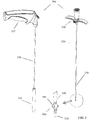
- a first embodiment of a stent 100, suitable for arytenoid abduction, is presented in the anterior perspective in FIG. 1 and the posterior perspective in FIG. 2 . While the description pertains to the treatment of the arytenoid cartilages, other embodiments of the invention, suitable for treatment of other pathologies is envisioned, and will be obvious to those of typical expertise in the field.
- the stent 100 is comprised of a Y-lock crown 110 that is resiliently connected to an anchor 120 .
- the Y-lock crown 110 is a resilient loop sized to diagonally set within the larynx immediately above the trachea.
- the proximal extremity of the Y-lock crown 110 comprising a center contact pad 130, may be deployed to exert an upward force under the apex of the vocal folds as a result of its resiliency.
- the magnitude of the upward force is determined, in part, by the mechanical properties of the stent and placement of the distal extremity 140 of the Y-lock crown 110 with respect to the center contact pad 130 .
- the outer periphery of the Y-lock crown 110 may also incorporate pads 150 configured to control contact properties such as contact pressure loading and contact friction.
- the distal extremity 140 of the Y-lock crown 110 is connected to the proximal extremity 160 of the anchor.
- stents of different geometries and resiliencies would be available for selection based on the specific application.
- the resiliency properties may be determined by the mechanical properties of the fabrication material and its dimensions (i.e. thickness, geometry, etc.).
- the Y-lock crown 110 may be configured so that the application of opposing axial forces 170 applied to the proximal and distal points of the resilient loop 110 cause the cross-sectional area to decrease. This feature may be used to advantage during placement wherein the stent may be inserted through narrow portions of the larynx.
- the anchor 120 in this embodiment, comprises four resilient loops 180 each of which is connected, at corresponding points, to anterior 190 and posterior 200 linear spines.
- the anterior linear spine 190 may comprise a deployment connector 210 at its distal extremity.
- additional deployment connectors (not shown) may be located at one or more of the extremities of the anterior 190 and posterior 200 linear spines.
- other embodiments comprising a greater or lesser number of resilient loops 180 is also envisioned.
- Each of the resilient loops 180 at rest, is sized to have a cross sectional area that, when projected on a plane perpendicular to the axis of the trachea, is greater than that of the trachea. Deployment of the anchor 120 may be facilitated by reducing the loop's 180 cross sectional area. Once emplaced in the trachea, the anchor's 120 resilient properties cause the cross-sectional dimensions of the anchor loops 180 to expand until conformal contact with the tracheal walls is established. This expansion anchors the stent with respect to the trachea.
- the outer surfaces of the anchor 120 may include contact pads (not shown) and/or be treated to enhance the frictional characteristics.
- the application of opposing forces 220 to the distal end of the anterior linear spine 190 and the proximal end of the posterior linear spine 200 cause the resilient loops 180 to stretch thereby reducing their cross sectional area permitting insertion into the trachea.
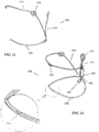
- a stent 400 is presented in Fig. 12 and 13 comprises a single resilient anchor loop 420 , a cantilever tail 415, and a Y-lock crown 410 .
- This stent 400 is suitable for being positioned in entirely within the subglottis.
- the single resilient anchor loop 420 when physically unconstrained, is sized to have a cross sectional area that, when projected on a plane perpendicular to the axis of the subglottis, is greater than that of the subglottis. Deployment of the anchor 420 may be facilitated by reducing the loop's 420 cross sectional area. Once emplaced, the anchor's 420 resilient properties cause the cross-sectional dimensions of the anchor loop 420 to expand until conformal contact with the subglottal walls is established, thereby anchoring the stent.
- the outer surfaces of the anchor loop 420 may include contact pads (not shown) and/or be treated to enhance the frictional characteristics.
- the single anchor loop further comprises a downward facing anchor loop notch or saddle 460 located at the anterior portion of the anchor loop 420 .
- the anchor loop notch 460 is configured to restrict slippage of tools employed during manipulation of the anchor loop 420 .
- a cantilever tail 415 is attached vertically to the posterior portion of the single resilient anchor loop, diametrically opposite to the anchor loop notch 460 .
- the cantilever tail 415 is vertically oriented approximately perpendicular to the plane of the anchor loop 420 .
- the cantilever tail 415 extends vertically upwards and is terminated by a tail tab 470 .
- the downward extension of the cantilever tail 415 is terminated by an attachment tab 480 .
- the anchor loop notch 460 may be used to attach the device to an alternate delivery system 300A .
- the Y-lock crown 410 is a resilient crown loop sized to diagonally set within the subglottis.
- the proximal extremity of the Y-lock crown 410 comprising a center contact pad 430, may be deployed to exert an upward force under the apex of the vocal folds as a result of its resiliency.
- the magnitude of the upward force is determined, in part, by the mechanical properties of the stent and placement of the distal extremity 440 of the Y-lock crown 410 with respect to the center contact pad 430 .
- the crown loop 410 is fastened, at a point opposite the center contact pad 430 , to the cantilever tail 415 in proximity to the anchor loop attachment point 490 .
- the outer periphery of the crown loop 410 may also incorporate pads 450 configured to control contact properties such as contact pressure loading and contact friction.
- the delivery system 300 comprises a cylindrical tube or cup 310 that is open at the proximal end.
- the cross-sectional area of the cylindrical cup 310 has a smaller cross section than the passageway of the larynx thereby facilitating insertion through the larynx.
- the proximal and distal edges of the cup 310 may be chamfered or beveled or otherwise configured to further facilitate stent insertion.
- the cup 310 may be equipped with an extended shaft 320 fastened parallel to the cylindrical axis of the delivery cup 310 .
- the length of the shaft 320 is sufficient to permit the cup 310 to be inserted into the trachea. It is envisioned that an assortment of cup diameters and lengths may be available from which one of appropriate dimensions for the particular application may be selected.
- the proximal end of the extended shaft 320 may comprise a handle 325 .
- the delivery system 300 further comprises a delivery wire component 330 that may be inserted into the throat to apply force to the appropriate portions of the stent 100 during emplacement, repositioning and removal procedures.
- the delivery wire component 330 may comprise an elongate hollow tube 340 containing a coaxial internal drive shaft 350 .
- the distal end of the internal drive shaft 350 may incorporate a coupler 360 that is activated by relative movement between the internal drive shaft 350 and the elongate hollow tube 340 .
- the proximal portion of the delivery system 300 may comprise an activation mechanism or handle 370 that is configured to activate the coupler 360 by causing relative movement of the internal drive shaft 350 with respect to the elongate hollow tube 340 .
- the coupler 360 may comprise a cylindrical cage or umbrella 380 having a distal end affixed to the distal end of the internal drive shaft 350 and a proximal end affixed to the distal end of the elongate hollow tube 340 .
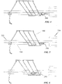
- the cylindrical cage 380 may comprise a plurality of flexible linear ribs 390 , parallel to the axis of the internal drive shaft 350 , arranged around the circumference of the internal drive shaft 350 . As illustrated in FIGs. 4 and 6 , differential linear movement of the internal drive shaft 350 with respect to the elongate hollow tube 340 causes the flexible linear ribs 390 of the cylindrical cage 380 to expand thereby increasing the outer diameter of the cage 380 .
- the coupler 360 In its expanded state, the coupler 360 will not pass through the deployment connector 210 and may be used to apply lateral force, required for stent deployment or removal.
- a manually activated mechanism 370 may be employed to supply differential linear movement necessary to expand the cage 380 .
- the tip of the internal drive shaft 350 incorporating the coupler 360 In its unexpanded state, as shown in FIG. 5 , the tip of the internal drive shaft 350 incorporating the coupler 360 may be pass through the deployment connector 210 .
- the coupler 5 60 comprises a notch or a gate opening at the distal end of the inner drive shaft 5 50 and a locking sleeve 570 at distal end of the cylindrical elongated outer tube 540 .
- Differential linear movement of the internal drive shaft 550 with respect to the elongate hollow tube 540 causes the inner drive shaft and locking sleeve to advance forward and expose the gate opening.
- the anchor loop notch will not pass through the gate opening and may be used to apply lateral force required for stent deployment or removal.
- the open state as shown in Fig.
- the gate opening is exposed and the device is released from the anchor loop notch 460 .
- the delivery wire assembly may further be utilized to assist in the reposition of the Y-Lock device.
- the delivery wire assembly gate mechanism may be secured to any portion of the Y-Lock device that can then be reposition by applying lateral force.
- the delivery wire assembly nose is smoothly formed to minimize the possibility of damage to the surrounding tissue.
- the delivery system may further comprise a 90° hook instrument to assist in placement or removal of the stent.
- the 90° hook instrument may comprise an elongate shaft with a 90° bend at its distal extremity. The end of the perpendicular portion of the hook instrument is smoothly formed to minimize the possibility of damage to the surrounding tissue.
- the stent 100 may be inserted into the delivery cup 310 by inwardly pulling the proximal extremity of the stent 100 into the delivery cup 310 .
- the inward pulling force may be exerted by the delivery wire component 330 coupled to the proximal deployment connector 210 .
- the stent's 100 flexibility allows it to deform as it is inserted into the delivery cup 310 .
- the cup 310 is of a length that can substantially contain the stent 100 in its deformed state.
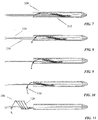
- Emplacement of the stent 100 is accomplished, as shown in FIGs. 7, 8, 9, 10, and 11 , by inserting the delivery cup 310 into the larynx and withdrawing the stent 100 from the delivery cup 310 .
- the withdrawing force may be exerted by the delivery wire component 330 coupled to the proximal deployment connector 210 .
- the stent 100 is fully contained within the delivery cup 310 .
- the stent 100 may be transported to the emplacement location within the larynx.
- the delivery wire component 330 is attached to the stent 100 at the deployment connector 210.
- FIGs. 8 and 9 show the stent 100 being deployed from the delivery cup 310 by application of a withdrawal force by means of the delivery wire component.
- FIG. 10 shows the Y-lock crown 110 fully deployed.
- the forward pad 130 may be positioned to exert an upward force under the apex of the vocal chords.
- continued application of the withdrawal force as shown in FIG. 11 , causes the anchor 120 to deploy from the cup 310 .
- the delivery wire component 330 may be used to deploy the stent 100 and to facilitate adjustment of its placement. After emplacement of the stent 100 , the delivery cup 310 and delivery wire component 330 may be withdrawn through opening formed by the deployed stent 100 .
- the stent 100 may be re-sheathed in the delivery cup 310 with the aid of the delivery wire component 330 .
- An exemplary procedure for deploying the stent in the larynx comprises the following sequence of steps:
- an exemplary procedure for retrieving the stent from the larynx comprises the following sequence of steps:
Landscapes
- Health & Medical Sciences (AREA)
- Engineering & Computer Science (AREA)
- Biomedical Technology (AREA)
- Life Sciences & Earth Sciences (AREA)
- Oral & Maxillofacial Surgery (AREA)
- Transplantation (AREA)
- Heart & Thoracic Surgery (AREA)
- Vascular Medicine (AREA)
- Cardiology (AREA)
- Animal Behavior & Ethology (AREA)
- General Health & Medical Sciences (AREA)
- Public Health (AREA)
- Veterinary Medicine (AREA)
- Prostheses (AREA)
- Gastroenterology & Hepatology (AREA)
- Pulmonology (AREA)
Claims (8)
- Kehlkopf/Trachea-Stent, umfassend:einen elastischen Ankerschleifenabschnitt, der entweder (a) eine einzelne elastische Ankerschleife (420) umfasst, die so bemessen ist, dass sie eine Querschnittsfläche aufweist, die, wenn sie auf eine Ebene senkrecht zur Achse der Subglottis projiziert wird, größer ist als diejenige der Subglottis für einen konformen Kontakt mit den Subglottiswänden, die Ankerschleife umfasst ferner eine nach unten gerichtete Ankerschleifenkerbe oder -sattel (460), der an dem vorderen Abschnitt der Ankerschleife angeordnet ist, oder (b) eine Mehrzahl von parallelen elastischen Ankerschleifen (180), die eine zylindrische Fläche definieren und für konformen Kontakt mit der Luftröhre ausdehnbar sind, wobei die elastischen Ankerschleifen an entsprechenden Punkten an ihrem Umfang durch mindestens zwei lineare Grate (190, 200) verbunden sind, wobei die linearen Grate parallel zur Achse der zylindrischen Fläche sind und mindestens einer der linearen Grate ein Absetzverbindungsstück (210) aufweist;wenn der elastische Ankerschleifenabschnitt die einzelne elastische Ankerschleife (420) umfasst, einen Freischwinger-Schweifabschnitt, der einen Freischwinger-Schweif (415) umfasst, der vertikal an einem hinteren Abschnitt der einzelnen elastischen Ankerschleife (420) befestigt ist, wobei der Freischwinger-Schweif ungefähr senkrecht zu der Ebene der Ankerschleife (460) ausgerichtet ist, wobei sich der Freischwinger-Schweif vertikal nach oben erstreckt und in einer Schweiföse (470) endet, wobei sich der Freischwinger-Schweif nach unten erstreckt und in einer Befestigungsöse (480) endet; undeinen Kronenabschnitt (110, 410) mit Y-Verschluss, der eine elastische Kronenschleife umfasst, die so bemessen ist, dass sie innerhalb der Subglottis diagonal gesetzt wird, wobei ihr proximales Ende ein mittiges Kontaktpolster (130, 430) umfasst, das zur Ausübung einer Aufwärtskraft auf den Scheitelpunkt der Stimmfalten infolge der Elastizität der Krone (110, 410) mit Y-Verschluss abgesetzt wird, wobei die Kronenschleife entweder (a) an einem Punkt gegenüber dem mittigen Kontaktpolster (430) an dem Freischwinger-Schweif (415) in der Nähe des Befestigungspunktes (490) der Ankerschleife befestigt ist oder (b) an einem Punkt an seinem Umfang gegenüber dem mittigen Kontaktpolster (130) mit einem der linearen Grate (200) in der Nähe einer der elastischen Ankerschleifen (180) flexibel zusammengefügt ist.
- Stent nach Anspruch 1, wobei der Y-Kronenabschnitt ferner ein oder mehrere Kontaktpolster (150, 450) umfasst, die am Umfang der elastischen Y-Kronenschleife (410) angeordnet und von dem mittleren Kontaktpolster (130, 430) beabstandet sind.
- Stent nach Anspruch 1 oder 2, wobei der Stent aus Nickel-Titan (d.h. Nitinol) gebildet und selbstausdehnend ist.
- Stent nach Anspruch 1, 2 oder 3, wobei die Außenflächen des Ankerabschnitts (420) und des Y-Kronenabschnitts (410) strukturiert sind.
- Stent nach einem vorhergehenden Anspruch, der ferner ein Zuführsystem umfasst.
- Stent nach Anspruch 5, wobei das Zuführsystem eine Zuführdrahtanordnung, eine Zuführbecheranordnung und ein 90-Grad-Hakeninstrument umfasst.
- Stent nach Anspruch 6, wobei die Zuführdrahtanordnung umfasst:ein zylindrisches Rohr (340), das einen beweglichen koaxialen Zuführdraht (350) enthält;eine Befestigungskupplung (360), die an einem distalen Ende des Zuführdrahts angeordnet und so konfiguriert ist, dass sie mit dem Absetzverbindungsstück (210) in Eingriff kommt; undeine Aktivierungsvorrichtung (370), die am proximalen Ende des Zuführdrahts (350) angeordnet ist, die durch den Zuführdraht mit der Befestigungskopplung (360) verbunden und wirkmäßig konfiguriert ist, um die Befestigungskopplung in Reaktion auf eine angewandte externe Kraft zu betätigen.
- Medizinprodukt nach Anspruch 6 oder 7, wobei die Zuführbecheranordnung umfasst:ein zylindrisches hohles Rohr, das einen Zuführbecher (310) mit einer Querschnittsfläche definiert, die kleiner als die Querschnittsfläche des Ankerteils ist;einen länglichen Schaft (320), der an seinem distalen Ende seitlich mit dem zylindrischen hohlen Rohr (310) verbunden und an seinem proximalen Ende an einem Griff (325) befestigt ist.
Applications Claiming Priority (3)
| Application Number | Priority Date | Filing Date | Title |
|---|---|---|---|
| US201461941589P | 2014-02-19 | 2014-02-19 | |
| US201462016252P | 2014-06-24 | 2014-06-24 | |
| PCT/US2015/016295 WO2015126893A1 (en) | 2014-02-19 | 2015-02-18 | A y-lock tracheal stent system and method of use |
Publications (3)
| Publication Number | Publication Date |
|---|---|
| EP3107491A1 EP3107491A1 (de) | 2016-12-28 |
| EP3107491A4 EP3107491A4 (de) | 2017-08-02 |
| EP3107491B1 true EP3107491B1 (de) | 2018-10-17 |
Family
ID=53797059
Family Applications (1)
| Application Number | Title | Priority Date | Filing Date |
|---|---|---|---|
| EP15751367.2A Active EP3107491B1 (de) | 2014-02-19 | 2015-02-18 | Luftröhrenstentsystem mit y-verschluss |
Country Status (3)
| Country | Link |
|---|---|
| US (1) | US9532889B2 (de) |
| EP (1) | EP3107491B1 (de) |
| WO (1) | WO2015126893A1 (de) |
Families Citing this family (2)
| Publication number | Priority date | Publication date | Assignee | Title |
|---|---|---|---|---|
| EP4663169A3 (de) * | 2019-06-21 | 2026-03-04 | Lazzaro Medical, LLC | Atemwegsunterstützungsvorrichtung |
| USD950730S1 (en) * | 2019-12-09 | 2022-05-03 | Lifenet Health | Medical implant device |
Family Cites Families (8)
| Publication number | Priority date | Publication date | Assignee | Title |
|---|---|---|---|---|
| DE4122923C1 (de) * | 1991-07-11 | 1993-01-28 | Willy Ruesch Ag, 7053 Kernen, De | |
| FR2750315B1 (fr) * | 1996-06-26 | 1998-12-18 | Novatech Inc | Prothese intralaryngee |
| US20030028255A1 (en) * | 2001-05-12 | 2003-02-06 | Hartig Gregory K. | Bioabsorbable exoluminal stent |
| ITRM20010554A1 (it) * | 2001-09-12 | 2003-03-12 | Univ Roma | Laringe artificiale. |
| US20040148032A1 (en) * | 2003-01-29 | 2004-07-29 | Rutter Michael John | Airway stent |
| US8196580B2 (en) * | 2006-05-11 | 2012-06-12 | Yossi Gross | Implantable respiration therapy device |
| US9265596B2 (en) * | 2009-09-11 | 2016-02-23 | Gi Dynamics, Inc. | Anchors with open heads |
| WO2012082791A2 (en) * | 2010-12-13 | 2012-06-21 | Quiescence Medical, Inc. | Apparatus and methods for treating sleep apnea |
-
2015
- 2015-02-18 EP EP15751367.2A patent/EP3107491B1/de active Active
- 2015-02-18 WO PCT/US2015/016295 patent/WO2015126893A1/en not_active Ceased
- 2015-02-18 US US14/624,851 patent/US9532889B2/en active Active
Non-Patent Citations (1)
| Title |
|---|
| None * |
Also Published As
| Publication number | Publication date |
|---|---|
| EP3107491A4 (de) | 2017-08-02 |
| US9532889B2 (en) | 2017-01-03 |
| WO2015126893A1 (en) | 2015-08-27 |
| US20150230948A1 (en) | 2015-08-20 |
| EP3107491A1 (de) | 2016-12-28 |
Similar Documents
| Publication | Publication Date | Title |
|---|---|---|
| US11666470B2 (en) | Pyloric anchor retrieval tools and methods | |
| EP3244844B1 (de) | Freisetzungssystem für naht- und drahtstent | |
| AU2007311646B2 (en) | System and method for positioning a stent graft | |
| JP5347175B2 (ja) | 導入器 | |
| CN102387759B (zh) | 用于吻合口的临时保护的外科手术装置 | |
| CN102014806B (zh) | 将扩张件置入套管中的方法 | |
| US6576008B2 (en) | Methods and device for inserting and withdrawing a two piece stent across a constricting anatomic structure | |
| KR20150040931A (ko) | 내강내 디바이스의 전개 시스템 | |
| US20120065571A1 (en) | Expandable pyloric anchors and methods for securing intestinal bypass sleeves | |
| AU2016203454B2 (en) | Microanchors for anchoring devices to body tissues | |
| KR20160147846A (ko) | 압입 및 견인식 의료 장치 전달 시스템 | |
| CN108261252A (zh) | 管腔支架及输送系统 | |
| EP2908770B1 (de) | Vorrichtung zur behandlung von obstruktiver schlafapnoe (osa) | |
| CN206934213U (zh) | 管腔支架及输送系统 | |
| CN105592803A (zh) | 锚固传送系统及方法 | |
| WO2018083632A1 (en) | Intraluminal device and method with fixation technique | |
| US9532889B2 (en) | Y-lock tracheal stent system and method of use | |
| CN112334096B (zh) | 多个胆道支架的部署 | |
| CN211610228U (zh) | 用于固定胃肠植入物的装置 | |
| CN113057773A (zh) | 一种可回收的管腔内植入器械及其应用 | |
| EP3040057A1 (de) | Protheseneinführungssysteme mit atraumatischer spitze zur verwendung mit auslösedrähten | |
| HK1235250B (en) | Microanchors for anchoring devices to body tissues |
Legal Events
| Date | Code | Title | Description |
|---|---|---|---|
| PUAI | Public reference made under article 153(3) epc to a published international application that has entered the european phase |
Free format text: ORIGINAL CODE: 0009012 |
|
| STAA | Information on the status of an ep patent application or granted ep patent |
Free format text: STATUS: REQUEST FOR EXAMINATION WAS MADE |
|
| 17P | Request for examination filed |
Effective date: 20160916 |
|
| AK | Designated contracting states |
Kind code of ref document: A1 Designated state(s): AL AT BE BG CH CY CZ DE DK EE ES FI FR GB GR HR HU IE IS IT LI LT LU LV MC MK MT NL NO PL PT RO RS SE SI SK SM TR |
|
| AX | Request for extension of the european patent |
Extension state: BA ME |
|
| DAX | Request for extension of the european patent (deleted) | ||
| A4 | Supplementary search report drawn up and despatched |
Effective date: 20170704 |
|
| RIC1 | Information provided on ipc code assigned before grant |
Ipc: A61F 2/04 20130101AFI20170628BHEP Ipc: A61F 2/844 20130101ALI20170628BHEP Ipc: A61F 2/966 20130101ALI20170628BHEP Ipc: A61F 2/06 20130101ALI20170628BHEP |
|
| GRAP | Despatch of communication of intention to grant a patent |
Free format text: ORIGINAL CODE: EPIDOSNIGR1 |
|
| STAA | Information on the status of an ep patent application or granted ep patent |
Free format text: STATUS: GRANT OF PATENT IS INTENDED |
|
| INTG | Intention to grant announced |
Effective date: 20180507 |
|
| GRAS | Grant fee paid |
Free format text: ORIGINAL CODE: EPIDOSNIGR3 |
|
| GRAA | (expected) grant |
Free format text: ORIGINAL CODE: 0009210 |
|
| STAA | Information on the status of an ep patent application or granted ep patent |
Free format text: STATUS: THE PATENT HAS BEEN GRANTED |
|
| AK | Designated contracting states |
Kind code of ref document: B1 Designated state(s): AL AT BE BG CH CY CZ DE DK EE ES FI FR GB GR HR HU IE IS IT LI LT LU LV MC MK MT NL NO PL PT RO RS SE SI SK SM TR |
|
| REG | Reference to a national code |
Ref country code: GB Ref legal event code: FG4D |
|
| REG | Reference to a national code |
Ref country code: CH Ref legal event code: EP |
|
| REG | Reference to a national code |
Ref country code: IE Ref legal event code: FG4D |
|
| REG | Reference to a national code |
Ref country code: DE Ref legal event code: R096 Ref document number: 602015018367 Country of ref document: DE Ref country code: AT Ref legal event code: REF Ref document number: 1053093 Country of ref document: AT Kind code of ref document: T Effective date: 20181115 |
|
| REG | Reference to a national code |
Ref country code: NL Ref legal event code: MP Effective date: 20181017 |
|
| REG | Reference to a national code |
Ref country code: LT Ref legal event code: MG4D |
|
| REG | Reference to a national code |
Ref country code: AT Ref legal event code: MK05 Ref document number: 1053093 Country of ref document: AT Kind code of ref document: T Effective date: 20181017 |
|
| PG25 | Lapsed in a contracting state [announced via postgrant information from national office to epo] |
Ref country code: NL Free format text: LAPSE BECAUSE OF FAILURE TO SUBMIT A TRANSLATION OF THE DESCRIPTION OR TO PAY THE FEE WITHIN THE PRESCRIBED TIME-LIMIT Effective date: 20181017 |
|
| PG25 | Lapsed in a contracting state [announced via postgrant information from national office to epo] |
Ref country code: IS Free format text: LAPSE BECAUSE OF FAILURE TO SUBMIT A TRANSLATION OF THE DESCRIPTION OR TO PAY THE FEE WITHIN THE PRESCRIBED TIME-LIMIT Effective date: 20190217 Ref country code: BG Free format text: LAPSE BECAUSE OF FAILURE TO SUBMIT A TRANSLATION OF THE DESCRIPTION OR TO PAY THE FEE WITHIN THE PRESCRIBED TIME-LIMIT Effective date: 20190117 Ref country code: LT Free format text: LAPSE BECAUSE OF FAILURE TO SUBMIT A TRANSLATION OF THE DESCRIPTION OR TO PAY THE FEE WITHIN THE PRESCRIBED TIME-LIMIT Effective date: 20181017 Ref country code: ES Free format text: LAPSE BECAUSE OF FAILURE TO SUBMIT A TRANSLATION OF THE DESCRIPTION OR TO PAY THE FEE WITHIN THE PRESCRIBED TIME-LIMIT Effective date: 20181017 Ref country code: HR Free format text: LAPSE BECAUSE OF FAILURE TO SUBMIT A TRANSLATION OF THE DESCRIPTION OR TO PAY THE FEE WITHIN THE PRESCRIBED TIME-LIMIT Effective date: 20181017 Ref country code: NO Free format text: LAPSE BECAUSE OF FAILURE TO SUBMIT A TRANSLATION OF THE DESCRIPTION OR TO PAY THE FEE WITHIN THE PRESCRIBED TIME-LIMIT Effective date: 20190117 Ref country code: PL Free format text: LAPSE BECAUSE OF FAILURE TO SUBMIT A TRANSLATION OF THE DESCRIPTION OR TO PAY THE FEE WITHIN THE PRESCRIBED TIME-LIMIT Effective date: 20181017 Ref country code: LV Free format text: LAPSE BECAUSE OF FAILURE TO SUBMIT A TRANSLATION OF THE DESCRIPTION OR TO PAY THE FEE WITHIN THE PRESCRIBED TIME-LIMIT Effective date: 20181017 Ref country code: AT Free format text: LAPSE BECAUSE OF FAILURE TO SUBMIT A TRANSLATION OF THE DESCRIPTION OR TO PAY THE FEE WITHIN THE PRESCRIBED TIME-LIMIT Effective date: 20181017 Ref country code: FI Free format text: LAPSE BECAUSE OF FAILURE TO SUBMIT A TRANSLATION OF THE DESCRIPTION OR TO PAY THE FEE WITHIN THE PRESCRIBED TIME-LIMIT Effective date: 20181017 |
|
| PG25 | Lapsed in a contracting state [announced via postgrant information from national office to epo] |
Ref country code: AL Free format text: LAPSE BECAUSE OF FAILURE TO SUBMIT A TRANSLATION OF THE DESCRIPTION OR TO PAY THE FEE WITHIN THE PRESCRIBED TIME-LIMIT Effective date: 20181017 Ref country code: SE Free format text: LAPSE BECAUSE OF FAILURE TO SUBMIT A TRANSLATION OF THE DESCRIPTION OR TO PAY THE FEE WITHIN THE PRESCRIBED TIME-LIMIT Effective date: 20181017 Ref country code: RS Free format text: LAPSE BECAUSE OF FAILURE TO SUBMIT A TRANSLATION OF THE DESCRIPTION OR TO PAY THE FEE WITHIN THE PRESCRIBED TIME-LIMIT Effective date: 20181017 Ref country code: GR Free format text: LAPSE BECAUSE OF FAILURE TO SUBMIT A TRANSLATION OF THE DESCRIPTION OR TO PAY THE FEE WITHIN THE PRESCRIBED TIME-LIMIT Effective date: 20190118 Ref country code: PT Free format text: LAPSE BECAUSE OF FAILURE TO SUBMIT A TRANSLATION OF THE DESCRIPTION OR TO PAY THE FEE WITHIN THE PRESCRIBED TIME-LIMIT Effective date: 20190217 |
|
| REG | Reference to a national code |
Ref country code: DE Ref legal event code: R097 Ref document number: 602015018367 Country of ref document: DE |
|
| PG25 | Lapsed in a contracting state [announced via postgrant information from national office to epo] |
Ref country code: IT Free format text: LAPSE BECAUSE OF FAILURE TO SUBMIT A TRANSLATION OF THE DESCRIPTION OR TO PAY THE FEE WITHIN THE PRESCRIBED TIME-LIMIT Effective date: 20181017 Ref country code: DK Free format text: LAPSE BECAUSE OF FAILURE TO SUBMIT A TRANSLATION OF THE DESCRIPTION OR TO PAY THE FEE WITHIN THE PRESCRIBED TIME-LIMIT Effective date: 20181017 Ref country code: CZ Free format text: LAPSE BECAUSE OF FAILURE TO SUBMIT A TRANSLATION OF THE DESCRIPTION OR TO PAY THE FEE WITHIN THE PRESCRIBED TIME-LIMIT Effective date: 20181017 |
|
| PLBE | No opposition filed within time limit |
Free format text: ORIGINAL CODE: 0009261 |
|
| STAA | Information on the status of an ep patent application or granted ep patent |
Free format text: STATUS: NO OPPOSITION FILED WITHIN TIME LIMIT |
|
| PG25 | Lapsed in a contracting state [announced via postgrant information from national office to epo] |
Ref country code: EE Free format text: LAPSE BECAUSE OF FAILURE TO SUBMIT A TRANSLATION OF THE DESCRIPTION OR TO PAY THE FEE WITHIN THE PRESCRIBED TIME-LIMIT Effective date: 20181017 Ref country code: SM Free format text: LAPSE BECAUSE OF FAILURE TO SUBMIT A TRANSLATION OF THE DESCRIPTION OR TO PAY THE FEE WITHIN THE PRESCRIBED TIME-LIMIT Effective date: 20181017 Ref country code: SK Free format text: LAPSE BECAUSE OF FAILURE TO SUBMIT A TRANSLATION OF THE DESCRIPTION OR TO PAY THE FEE WITHIN THE PRESCRIBED TIME-LIMIT Effective date: 20181017 Ref country code: RO Free format text: LAPSE BECAUSE OF FAILURE TO SUBMIT A TRANSLATION OF THE DESCRIPTION OR TO PAY THE FEE WITHIN THE PRESCRIBED TIME-LIMIT Effective date: 20181017 |
|
| 26N | No opposition filed |
Effective date: 20190718 |
|
| REG | Reference to a national code |
Ref country code: CH Ref legal event code: PL |
|
| PG25 | Lapsed in a contracting state [announced via postgrant information from national office to epo] |
Ref country code: LU Free format text: LAPSE BECAUSE OF NON-PAYMENT OF DUE FEES Effective date: 20190218 Ref country code: SI Free format text: LAPSE BECAUSE OF FAILURE TO SUBMIT A TRANSLATION OF THE DESCRIPTION OR TO PAY THE FEE WITHIN THE PRESCRIBED TIME-LIMIT Effective date: 20181017 Ref country code: MC Free format text: LAPSE BECAUSE OF FAILURE TO SUBMIT A TRANSLATION OF THE DESCRIPTION OR TO PAY THE FEE WITHIN THE PRESCRIBED TIME-LIMIT Effective date: 20181017 |
|
| REG | Reference to a national code |
Ref country code: BE Ref legal event code: MM Effective date: 20190228 |
|
| REG | Reference to a national code |
Ref country code: IE Ref legal event code: MM4A |
|
| PG25 | Lapsed in a contracting state [announced via postgrant information from national office to epo] |
Ref country code: LI Free format text: LAPSE BECAUSE OF NON-PAYMENT OF DUE FEES Effective date: 20190228 Ref country code: CH Free format text: LAPSE BECAUSE OF NON-PAYMENT OF DUE FEES Effective date: 20190228 |
|
| PG25 | Lapsed in a contracting state [announced via postgrant information from national office to epo] |
Ref country code: IE Free format text: LAPSE BECAUSE OF NON-PAYMENT OF DUE FEES Effective date: 20190218 |
|
| PG25 | Lapsed in a contracting state [announced via postgrant information from national office to epo] |
Ref country code: BE Free format text: LAPSE BECAUSE OF NON-PAYMENT OF DUE FEES Effective date: 20190228 |
|
| PG25 | Lapsed in a contracting state [announced via postgrant information from national office to epo] |
Ref country code: TR Free format text: LAPSE BECAUSE OF FAILURE TO SUBMIT A TRANSLATION OF THE DESCRIPTION OR TO PAY THE FEE WITHIN THE PRESCRIBED TIME-LIMIT Effective date: 20181017 |
|
| PG25 | Lapsed in a contracting state [announced via postgrant information from national office to epo] |
Ref country code: MT Free format text: LAPSE BECAUSE OF NON-PAYMENT OF DUE FEES Effective date: 20190218 |
|
| PG25 | Lapsed in a contracting state [announced via postgrant information from national office to epo] |
Ref country code: CY Free format text: LAPSE BECAUSE OF FAILURE TO SUBMIT A TRANSLATION OF THE DESCRIPTION OR TO PAY THE FEE WITHIN THE PRESCRIBED TIME-LIMIT Effective date: 20181017 |
|
| PG25 | Lapsed in a contracting state [announced via postgrant information from national office to epo] |
Ref country code: HU Free format text: LAPSE BECAUSE OF FAILURE TO SUBMIT A TRANSLATION OF THE DESCRIPTION OR TO PAY THE FEE WITHIN THE PRESCRIBED TIME-LIMIT; INVALID AB INITIO Effective date: 20150218 |
|
| PG25 | Lapsed in a contracting state [announced via postgrant information from national office to epo] |
Ref country code: MK Free format text: LAPSE BECAUSE OF FAILURE TO SUBMIT A TRANSLATION OF THE DESCRIPTION OR TO PAY THE FEE WITHIN THE PRESCRIBED TIME-LIMIT Effective date: 20181017 |
|
| PGFP | Annual fee paid to national office [announced via postgrant information from national office to epo] |
Ref country code: GB Payment date: 20260227 Year of fee payment: 12 |
|
| PGFP | Annual fee paid to national office [announced via postgrant information from national office to epo] |
Ref country code: DE Payment date: 20260227 Year of fee payment: 12 |
|
| PGFP | Annual fee paid to national office [announced via postgrant information from national office to epo] |
Ref country code: FR Payment date: 20260225 Year of fee payment: 12 |