EP3107707B1 - Vorrichtung zum extrudieren von kunststoffen - Google Patents
Vorrichtung zum extrudieren von kunststoffen Download PDFInfo
- Publication number
- EP3107707B1 EP3107707B1 EP15752829.0A EP15752829A EP3107707B1 EP 3107707 B1 EP3107707 B1 EP 3107707B1 EP 15752829 A EP15752829 A EP 15752829A EP 3107707 B1 EP3107707 B1 EP 3107707B1
- Authority
- EP
- European Patent Office
- Prior art keywords
- melting
- insert
- channels
- barrel
- propeller
- Prior art date
- Legal status (The legal status is an assumption and is not a legal conclusion. Google has not performed a legal analysis and makes no representation as to the accuracy of the status listed.)
- Active
Links
Images





Classifications
-
- B—PERFORMING OPERATIONS; TRANSPORTING
- B29—WORKING OF PLASTICS; WORKING OF SUBSTANCES IN A PLASTIC STATE IN GENERAL
- B29C—SHAPING OR JOINING OF PLASTICS; SHAPING OF MATERIAL IN A PLASTIC STATE, NOT OTHERWISE PROVIDED FOR; AFTER-TREATMENT OF THE SHAPED PRODUCTS, e.g. REPAIRING
- B29C48/00—Extrusion moulding, i.e. expressing the moulding material through a die or nozzle which imparts the desired form; Apparatus therefor
- B29C48/25—Component parts, details or accessories; Auxiliary operations
- B29C48/78—Thermal treatment of the extrusion moulding material or of preformed parts or layers, e.g. by heating or cooling
- B29C48/80—Thermal treatment of the extrusion moulding material or of preformed parts or layers, e.g. by heating or cooling at the plasticising zone, e.g. by heating cylinders
- B29C48/802—Heating
-
- B—PERFORMING OPERATIONS; TRANSPORTING
- B29—WORKING OF PLASTICS; WORKING OF SUBSTANCES IN A PLASTIC STATE IN GENERAL
- B29B—PREPARATION OR PRETREATMENT OF THE MATERIAL TO BE SHAPED; MAKING GRANULES OR PREFORMS; RECOVERY OF PLASTICS OR OTHER CONSTITUENTS OF WASTE MATERIAL CONTAINING PLASTICS
- B29B7/00—Mixing; Kneading
- B29B7/30—Mixing; Kneading continuous, with mechanical mixing or kneading devices
- B29B7/34—Mixing; Kneading continuous, with mechanical mixing or kneading devices with movable mixing or kneading devices
- B29B7/38—Mixing; Kneading continuous, with mechanical mixing or kneading devices with movable mixing or kneading devices rotary
- B29B7/40—Mixing; Kneading continuous, with mechanical mixing or kneading devices with movable mixing or kneading devices rotary with single shaft
- B29B7/42—Mixing; Kneading continuous, with mechanical mixing or kneading devices with movable mixing or kneading devices rotary with single shaft with screw or helix
- B29B7/421—Mixing; Kneading continuous, with mechanical mixing or kneading devices with movable mixing or kneading devices rotary with single shaft with screw or helix with screw and additionally other mixing elements on the same shaft, e.g. paddles, discs, bearings, rotor blades of the Banbury type
-
- B—PERFORMING OPERATIONS; TRANSPORTING
- B29—WORKING OF PLASTICS; WORKING OF SUBSTANCES IN A PLASTIC STATE IN GENERAL
- B29B—PREPARATION OR PRETREATMENT OF THE MATERIAL TO BE SHAPED; MAKING GRANULES OR PREFORMS; RECOVERY OF PLASTICS OR OTHER CONSTITUENTS OF WASTE MATERIAL CONTAINING PLASTICS
- B29B7/00—Mixing; Kneading
- B29B7/30—Mixing; Kneading continuous, with mechanical mixing or kneading devices
- B29B7/34—Mixing; Kneading continuous, with mechanical mixing or kneading devices with movable mixing or kneading devices
- B29B7/38—Mixing; Kneading continuous, with mechanical mixing or kneading devices with movable mixing or kneading devices rotary
- B29B7/40—Mixing; Kneading continuous, with mechanical mixing or kneading devices with movable mixing or kneading devices rotary with single shaft
- B29B7/42—Mixing; Kneading continuous, with mechanical mixing or kneading devices with movable mixing or kneading devices rotary with single shaft with screw or helix
- B29B7/428—Parts or accessories, e.g. casings, feeding or discharging means
-
- B—PERFORMING OPERATIONS; TRANSPORTING
- B29—WORKING OF PLASTICS; WORKING OF SUBSTANCES IN A PLASTIC STATE IN GENERAL
- B29C—SHAPING OR JOINING OF PLASTICS; SHAPING OF MATERIAL IN A PLASTIC STATE, NOT OTHERWISE PROVIDED FOR; AFTER-TREATMENT OF THE SHAPED PRODUCTS, e.g. REPAIRING
- B29C48/00—Extrusion moulding, i.e. expressing the moulding material through a die or nozzle which imparts the desired form; Apparatus therefor
- B29C48/03—Extrusion moulding, i.e. expressing the moulding material through a die or nozzle which imparts the desired form; Apparatus therefor characterised by the shape of the extruded material at extrusion
- B29C48/05—Filamentary, e.g. strands
-
- B—PERFORMING OPERATIONS; TRANSPORTING
- B29—WORKING OF PLASTICS; WORKING OF SUBSTANCES IN A PLASTIC STATE IN GENERAL
- B29C—SHAPING OR JOINING OF PLASTICS; SHAPING OF MATERIAL IN A PLASTIC STATE, NOT OTHERWISE PROVIDED FOR; AFTER-TREATMENT OF THE SHAPED PRODUCTS, e.g. REPAIRING
- B29C48/00—Extrusion moulding, i.e. expressing the moulding material through a die or nozzle which imparts the desired form; Apparatus therefor
- B29C48/25—Component parts, details or accessories; Auxiliary operations
- B29C48/256—Exchangeable extruder parts
- B29C48/2568—Inserts
- B29C48/25684—Inserts for barrels
-
- B—PERFORMING OPERATIONS; TRANSPORTING
- B29—WORKING OF PLASTICS; WORKING OF SUBSTANCES IN A PLASTIC STATE IN GENERAL
- B29C—SHAPING OR JOINING OF PLASTICS; SHAPING OF MATERIAL IN A PLASTIC STATE, NOT OTHERWISE PROVIDED FOR; AFTER-TREATMENT OF THE SHAPED PRODUCTS, e.g. REPAIRING
- B29C48/00—Extrusion moulding, i.e. expressing the moulding material through a die or nozzle which imparts the desired form; Apparatus therefor
- B29C48/25—Component parts, details or accessories; Auxiliary operations
- B29C48/275—Recovery or reuse of energy or materials
- B29C48/277—Recovery or reuse of energy or materials of materials
-
- B—PERFORMING OPERATIONS; TRANSPORTING
- B29—WORKING OF PLASTICS; WORKING OF SUBSTANCES IN A PLASTIC STATE IN GENERAL
- B29C—SHAPING OR JOINING OF PLASTICS; SHAPING OF MATERIAL IN A PLASTIC STATE, NOT OTHERWISE PROVIDED FOR; AFTER-TREATMENT OF THE SHAPED PRODUCTS, e.g. REPAIRING
- B29C48/00—Extrusion moulding, i.e. expressing the moulding material through a die or nozzle which imparts the desired form; Apparatus therefor
- B29C48/25—Component parts, details or accessories; Auxiliary operations
- B29C48/36—Means for plasticising or homogenising the moulding material or forcing it through the nozzle or die
- B29C48/362—Means for plasticising or homogenising the moulding material or forcing it through the nozzle or die using static mixing devices
-
- B—PERFORMING OPERATIONS; TRANSPORTING
- B29—WORKING OF PLASTICS; WORKING OF SUBSTANCES IN A PLASTIC STATE IN GENERAL
- B29C—SHAPING OR JOINING OF PLASTICS; SHAPING OF MATERIAL IN A PLASTIC STATE, NOT OTHERWISE PROVIDED FOR; AFTER-TREATMENT OF THE SHAPED PRODUCTS, e.g. REPAIRING
- B29C48/00—Extrusion moulding, i.e. expressing the moulding material through a die or nozzle which imparts the desired form; Apparatus therefor
- B29C48/25—Component parts, details or accessories; Auxiliary operations
- B29C48/36—Means for plasticising or homogenising the moulding material or forcing it through the nozzle or die
- B29C48/50—Details of extruders
- B29C48/505—Screws
- B29C48/54—Screws with additional forward-feeding elements
-
- B—PERFORMING OPERATIONS; TRANSPORTING
- B29—WORKING OF PLASTICS; WORKING OF SUBSTANCES IN A PLASTIC STATE IN GENERAL
- B29C—SHAPING OR JOINING OF PLASTICS; SHAPING OF MATERIAL IN A PLASTIC STATE, NOT OTHERWISE PROVIDED FOR; AFTER-TREATMENT OF THE SHAPED PRODUCTS, e.g. REPAIRING
- B29C48/00—Extrusion moulding, i.e. expressing the moulding material through a die or nozzle which imparts the desired form; Apparatus therefor
- B29C48/25—Component parts, details or accessories; Auxiliary operations
- B29C48/36—Means for plasticising or homogenising the moulding material or forcing it through the nozzle or die
- B29C48/50—Details of extruders
- B29C48/505—Screws
- B29C48/625—Screws characterised by the ratio of the threaded length of the screw to its outside diameter [L/D ratio]
-
- B—PERFORMING OPERATIONS; TRANSPORTING
- B29—WORKING OF PLASTICS; WORKING OF SUBSTANCES IN A PLASTIC STATE IN GENERAL
- B29C—SHAPING OR JOINING OF PLASTICS; SHAPING OF MATERIAL IN A PLASTIC STATE, NOT OTHERWISE PROVIDED FOR; AFTER-TREATMENT OF THE SHAPED PRODUCTS, e.g. REPAIRING
- B29C48/00—Extrusion moulding, i.e. expressing the moulding material through a die or nozzle which imparts the desired form; Apparatus therefor
- B29C48/25—Component parts, details or accessories; Auxiliary operations
- B29C48/36—Means for plasticising or homogenising the moulding material or forcing it through the nozzle or die
- B29C48/50—Details of extruders
- B29C48/505—Screws
- B29C48/67—Screws having incorporated mixing devices not provided for in groups B29C48/52 - B29C48/66
-
- B—PERFORMING OPERATIONS; TRANSPORTING
- B29—WORKING OF PLASTICS; WORKING OF SUBSTANCES IN A PLASTIC STATE IN GENERAL
- B29C—SHAPING OR JOINING OF PLASTICS; SHAPING OF MATERIAL IN A PLASTIC STATE, NOT OTHERWISE PROVIDED FOR; AFTER-TREATMENT OF THE SHAPED PRODUCTS, e.g. REPAIRING
- B29C48/00—Extrusion moulding, i.e. expressing the moulding material through a die or nozzle which imparts the desired form; Apparatus therefor
- B29C48/25—Component parts, details or accessories; Auxiliary operations
- B29C48/36—Means for plasticising or homogenising the moulding material or forcing it through the nozzle or die
- B29C48/50—Details of extruders
- B29C48/68—Barrels or cylinders
-
- B—PERFORMING OPERATIONS; TRANSPORTING
- B29—WORKING OF PLASTICS; WORKING OF SUBSTANCES IN A PLASTIC STATE IN GENERAL
- B29C—SHAPING OR JOINING OF PLASTICS; SHAPING OF MATERIAL IN A PLASTIC STATE, NOT OTHERWISE PROVIDED FOR; AFTER-TREATMENT OF THE SHAPED PRODUCTS, e.g. REPAIRING
- B29C48/00—Extrusion moulding, i.e. expressing the moulding material through a die or nozzle which imparts the desired form; Apparatus therefor
- B29C48/25—Component parts, details or accessories; Auxiliary operations
- B29C48/36—Means for plasticising or homogenising the moulding material or forcing it through the nozzle or die
- B29C48/50—Details of extruders
- B29C48/69—Filters or screens for the moulding material
- B29C48/694—Cylindrical or conical filters
-
- B—PERFORMING OPERATIONS; TRANSPORTING
- B29—WORKING OF PLASTICS; WORKING OF SUBSTANCES IN A PLASTIC STATE IN GENERAL
- B29C—SHAPING OR JOINING OF PLASTICS; SHAPING OF MATERIAL IN A PLASTIC STATE, NOT OTHERWISE PROVIDED FOR; AFTER-TREATMENT OF THE SHAPED PRODUCTS, e.g. REPAIRING
- B29C48/00—Extrusion moulding, i.e. expressing the moulding material through a die or nozzle which imparts the desired form; Apparatus therefor
- B29C48/25—Component parts, details or accessories; Auxiliary operations
- B29C48/78—Thermal treatment of the extrusion moulding material or of preformed parts or layers, e.g. by heating or cooling
- B29C48/80—Thermal treatment of the extrusion moulding material or of preformed parts or layers, e.g. by heating or cooling at the plasticising zone, e.g. by heating cylinders
- B29C48/83—Heating or cooling the cylinders
- B29C48/832—Heating
-
- B—PERFORMING OPERATIONS; TRANSPORTING
- B29—WORKING OF PLASTICS; WORKING OF SUBSTANCES IN A PLASTIC STATE IN GENERAL
- B29C—SHAPING OR JOINING OF PLASTICS; SHAPING OF MATERIAL IN A PLASTIC STATE, NOT OTHERWISE PROVIDED FOR; AFTER-TREATMENT OF THE SHAPED PRODUCTS, e.g. REPAIRING
- B29C48/00—Extrusion moulding, i.e. expressing the moulding material through a die or nozzle which imparts the desired form; Apparatus therefor
- B29C48/25—Component parts, details or accessories; Auxiliary operations
- B29C48/92—Measuring, controlling or regulating
-
- B—PERFORMING OPERATIONS; TRANSPORTING
- B29—WORKING OF PLASTICS; WORKING OF SUBSTANCES IN A PLASTIC STATE IN GENERAL
- B29C—SHAPING OR JOINING OF PLASTICS; SHAPING OF MATERIAL IN A PLASTIC STATE, NOT OTHERWISE PROVIDED FOR; AFTER-TREATMENT OF THE SHAPED PRODUCTS, e.g. REPAIRING
- B29C2948/00—Indexing scheme relating to extrusion moulding
- B29C2948/92—Measuring, controlling or regulating
- B29C2948/92504—Controlled parameter
- B29C2948/92704—Temperature
-
- B—PERFORMING OPERATIONS; TRANSPORTING
- B29—WORKING OF PLASTICS; WORKING OF SUBSTANCES IN A PLASTIC STATE IN GENERAL
- B29C—SHAPING OR JOINING OF PLASTICS; SHAPING OF MATERIAL IN A PLASTIC STATE, NOT OTHERWISE PROVIDED FOR; AFTER-TREATMENT OF THE SHAPED PRODUCTS, e.g. REPAIRING
- B29C2948/00—Indexing scheme relating to extrusion moulding
- B29C2948/92—Measuring, controlling or regulating
- B29C2948/92819—Location or phase of control
- B29C2948/92857—Extrusion unit
- B29C2948/92876—Feeding, melting, plasticising or pumping zones, e.g. the melt itself
-
- B—PERFORMING OPERATIONS; TRANSPORTING
- B29—WORKING OF PLASTICS; WORKING OF SUBSTANCES IN A PLASTIC STATE IN GENERAL
- B29C—SHAPING OR JOINING OF PLASTICS; SHAPING OF MATERIAL IN A PLASTIC STATE, NOT OTHERWISE PROVIDED FOR; AFTER-TREATMENT OF THE SHAPED PRODUCTS, e.g. REPAIRING
- B29C48/00—Extrusion moulding, i.e. expressing the moulding material through a die or nozzle which imparts the desired form; Apparatus therefor
- B29C48/02—Small extruding apparatus, e.g. handheld, toy or laboratory extruders
-
- B—PERFORMING OPERATIONS; TRANSPORTING
- B29—WORKING OF PLASTICS; WORKING OF SUBSTANCES IN A PLASTIC STATE IN GENERAL
- B29C—SHAPING OR JOINING OF PLASTICS; SHAPING OF MATERIAL IN A PLASTIC STATE, NOT OTHERWISE PROVIDED FOR; AFTER-TREATMENT OF THE SHAPED PRODUCTS, e.g. REPAIRING
- B29C48/00—Extrusion moulding, i.e. expressing the moulding material through a die or nozzle which imparts the desired form; Apparatus therefor
- B29C48/25—Component parts, details or accessories; Auxiliary operations
- B29C48/285—Feeding the extrusion material to the extruder
- B29C48/288—Feeding the extrusion material to the extruder in solid form, e.g. powder or granules
-
- B—PERFORMING OPERATIONS; TRANSPORTING
- B29—WORKING OF PLASTICS; WORKING OF SUBSTANCES IN A PLASTIC STATE IN GENERAL
- B29C—SHAPING OR JOINING OF PLASTICS; SHAPING OF MATERIAL IN A PLASTIC STATE, NOT OTHERWISE PROVIDED FOR; AFTER-TREATMENT OF THE SHAPED PRODUCTS, e.g. REPAIRING
- B29C48/00—Extrusion moulding, i.e. expressing the moulding material through a die or nozzle which imparts the desired form; Apparatus therefor
- B29C48/25—Component parts, details or accessories; Auxiliary operations
- B29C48/36—Means for plasticising or homogenising the moulding material or forcing it through the nozzle or die
- B29C48/50—Details of extruders
- B29C48/695—Flow dividers, e.g. breaker plates
- B29C48/70—Flow dividers, e.g. breaker plates comprising means for dividing, distributing and recombining melt flows
- B29C48/705—Flow dividers, e.g. breaker plates comprising means for dividing, distributing and recombining melt flows in the die zone, e.g. to create flow homogeneity
-
- Y—GENERAL TAGGING OF NEW TECHNOLOGICAL DEVELOPMENTS; GENERAL TAGGING OF CROSS-SECTIONAL TECHNOLOGIES SPANNING OVER SEVERAL SECTIONS OF THE IPC; TECHNICAL SUBJECTS COVERED BY FORMER USPC CROSS-REFERENCE ART COLLECTIONS [XRACs] AND DIGESTS
- Y02—TECHNOLOGIES OR APPLICATIONS FOR MITIGATION OR ADAPTATION AGAINST CLIMATE CHANGE
- Y02P—CLIMATE CHANGE MITIGATION TECHNOLOGIES IN THE PRODUCTION OR PROCESSING OF GOODS
- Y02P70/00—Climate change mitigation technologies in the production process for final industrial or consumer products
- Y02P70/10—Greenhouse gas [GHG] capture, material saving, heat recovery or other energy efficient measures, e.g. motor control, characterised by manufacturing processes, e.g. for rolling metal or metal working
-
- Y—GENERAL TAGGING OF NEW TECHNOLOGICAL DEVELOPMENTS; GENERAL TAGGING OF CROSS-SECTIONAL TECHNOLOGIES SPANNING OVER SEVERAL SECTIONS OF THE IPC; TECHNICAL SUBJECTS COVERED BY FORMER USPC CROSS-REFERENCE ART COLLECTIONS [XRACs] AND DIGESTS
- Y02—TECHNOLOGIES OR APPLICATIONS FOR MITIGATION OR ADAPTATION AGAINST CLIMATE CHANGE
- Y02W—CLIMATE CHANGE MITIGATION TECHNOLOGIES RELATED TO WASTEWATER TREATMENT OR WASTE MANAGEMENT
- Y02W30/00—Technologies for solid waste management
- Y02W30/50—Reuse, recycling or recovery technologies
- Y02W30/62—Plastics recycling; Rubber recycling
Definitions
- the disclosure relates generally to the extrusion of plastic materials, and more particularly to an apparatus for extruding plastic materials.
- US 4,249,877 A relates to an extruder for thermoplastics having a directly motor-driven high-speed feed screw which mechanically force-feeds raw plastic pellets, pushing them forward under high pressure into a heat-transfer zone for melting, and finally through a static mixer, to deliver a pressurized homogeneous melt to an extrusion die.
- US 3,989,434 A relates to mixing means in the form of a torpedo for an injection molding machine having a plurality of alternately isolated and intersecting flow paths for repeatedly dividing and recombining material flow streams to achieve uniform properties throughout the material.
- the paths are formed as right and left-hand helical channels on the circumference of the torpedo body, with the helixes of one hand having a pitch different from that of the other such that the flow paths intersect in a pattern, which is bilaterally asymmetrical with respect to an axial net flow direction.
- DE 70 13 580 U relates to an extruder for products of plastic material, wherein the extruder is provided with a device between head and screw.
- the device consists essentially of at least two sets of channels through which the molten plastic material pressed by the screw passes into the extruder head, wherein the channel of one set overlaps those of the other set.
- US 7,032,843 B1 relates to a mixing nozzle, which includes a casing and mixer.
- the mixer fits within the casing and includes alternating elongated helical flow directing lands and notched barrier lands.
- the flow directing lands extend from the body and seal against the inside wall of the casing.
- the barrier lands also extend from the body but are offset from said inside wall of the casing.
- the flow directing lands and the barrier lands have differing helix angles and thus define alternating converging inlet channels and diverging outlet channels.
- Mixing of molten plastic is accomplished when the molten plastic is received from the inlet end of the mixing portion primarily by the inlet channels, passes over the barrier lands and through the notches in the barrier lands and passes primarily via the outlet channels through the outlet end of the mixer.
- US 3,762,692 A relates to a conventional screw extruder for thermoplastic melts with temperature equalizing head in which the free end of the screw near the discharge outlet in the barrel housing of the extruder is equipped with a slotted head member to provide a large number of circumferentially distributed ribs with a radial extension or corresponding depth of the slots which is sufficient to achieve a temperature equalization of the extruded polymer melt.
- Plastic is becoming more and more popular for use in all fields for its easy handling, non-reactivity, and other properties.
- One popular form of plastic is extrudate, which may be used in 3D printing, plastic welding, and so on.
- processed plastic like rod, wire, or filament is still relatively expensive compared to the raw materials.
- 3D printing filament e.g. processed plastic material
- 3D printing filament ranges from $20-50 per kilogram compared to $1-5 per kilogram of raw plastic pellets.
- manufacturing and processing of the plastic material is almost always done in industrial-scale factories or sites, and the processed product then needs to be transported to the vendors and/or consumers, as such, lots of time, energy, and money are often spent on transportation alone.
- plastic material e.g. 3D printing/ prototyping, shipping/packaging and so on
- 3D printing/ prototyping shipping/packaging and so on
- waste materials which must be re-transported and processed for recycling.
- the quantity and/or quality of recycled plastic material is not worth the energy of separation, cleaning, and processing required by mass recirculation. This is an issue for the typical consumer as well as placing plastic waste in a recycling bin can be an inconvenience for the average consumer.
- These un-recycled plastics can end up in our parks, landfills and oceans and cause environmental damage in the long-run.
- the disclosure relates generally to devices, apparatus and methods for extruding materials including plastics such as thermoplastics.
- devices, apparatus and methods disclosed herein may reduce or eliminate the need for complex controls and mechanics, which can result in lower overall costs, more energy efficient, and ease of control and operation in relation to existing extrusion systems.
- the devices, apparatus and methods described herein can be used in conjunction with a plastic grinder or reducer to repurpose any suitable plastic material (e.g., thermoplastics) into extrudate.
- devices, apparatus and methods described may be used to extrude filament suitable for existing 3D printing devices and therefore may allow the sourcing of printing "ink” from any raw or waste (e.g., recycled) plastics.
- materials suitable for use with the devices, apparatus and methods disclosed herein may include polylactide (PLA), acrylonitrile butadiene styrene (ABS), Polyethylene terephthalate (PET) and Nylon plastics.
- devices, apparatus and methods disclosed herein may allow the typical consumer to: a) easily produce their own plastic extrusions at home, using any suitable source of material they desire; and b) recycle plastics at home on a small scale, turning waste plastics back into usable materials with minimal energy, transportation, and industrial processes required.
- This can help reduce the overall energy footprint in recycling and processing of plastics, and can increase the amount of plastics that can be recycled, as the recycling can be done on a much smaller scale with minimal to moderate energy consumption.
- teachings of the present disclosure are not limited to home-scale extrusion processes but may also be apply to industrial (e.g., plastic) extrusion processes.
- FIG. 1 is an axial cross-sectional view of an exemplary apparatus 10 for extruding suitable plastic material(s).
- Apparatus 10 may comprise feeding portion 12, melting portion 14 and output die 16.
- Feeding portion 12 may comprise hopper 18 into which material(s) to be extruded may be received via feed opening 11.
- the material to be extruded may be in particle (e.g., pellet) form of suitable size and shape.
- Feeding portion 12 may also comprise propeller 20 which may serve to propel the material from hopper 18 toward melting portion 14.
- Propeller 20 may, for example, comprise an auger configured to rotate substantially about axis A and to direct the material substantially along a flow direction, which may be substantially parallel to axis A.
- Propeller 20 may be disposed inside feeding barrel 21.
- Propeller 20 may extend only in feeding portion 12.
- propeller 21 may be disposed entirely outside of melting portion 14 so that no part of propeller 20 (e.g., auger) may extend in melting portion 14.
- Melting portion 14 may be in communication with feeding portion 12 so that melting portion 14 may receive the material from feeding portion 12. Melting portion 14 may also be configured to transmit heat into the material received into melting chamber 28 from feeding portion 12. Melting portion 14 may comprise one or more heating sources connected to or otherwise coupled to melting barrel 24 in order to heat the material inside melting chamber 28. Heat may be transmitted via a suitable heating means such as heater 22. Heater 22 may comprise any suitable heating device for injecting heat into melting portion 14. For example, heater 22 may comprise one or more types of heater elements suitable for the purpose of extrusion, such as electrical heaters, nozzle heaters, band heaters, cartridge heaters and so on. In various embodiments, heater 22 may comprise a suitable heater band that is typically used in existing extrusion devices.
- Melting portion 14 may comprise melting barrel 24 having inner surface 26 defining melting chamber 28.
- Melting chamber 28 may be in communication with feeding portion 12 in order to receive the material delivered by propeller 20.
- Melting chamber 28 may have a portion of which that may, but not necessarily, have a substantially circular cross-section.
- melting chamber 28 may have a substantially cylindrical portion that substantially extends along axis A.
- Melting portion 14 may also comprise one or more melting inserts 30, which may, as explained further below, assist in melting the material to be extruded flowing inside melting chamber and toward output die 16.
- Output die 16 may be in communication with melting portion 14 to permit extrusion of the material received from melting portion 14.
- Output die 16 may have any suitable cross-sectional shape defining the cross-section of the extrudate produced.
- the cross-sectional shape of output die 16 may be substantially circular or have another cross-sectional shape suitable for extruding filament for known or other 3D printing machines.
- output die 16 may have any suitable cross-sectional shape and area to produce, for example, thread, film, plastic welding rod or other type(s) of extrudate suitable for applications other than 3D printing.
- Screen 32 e.g., breaker plate
- Thermal insulator 34 may be disposed between feeding portion 12 and melting portion 14. Thermal insulator 34 may hinder heat transfer from melting portion 14 to feeding portion 12. In various embodiments, thermal insulator 34 may at least partially prevent direct conductive heat transfer between melting barrel 24 and feeding barrel 21.
- melting barrel 24 and feeding barrel 21 may comprise metallic material(s)
- thermal insulator 34 may comprise one or more materials (i.e., silica, ceramic, metal oxide(s) and glass) having a lower thermal conductivity coefficient than melting barrel 24 and feeding barrel 21.
- thermal insulator 34 may comprise a suitable ceramic spacer disposed between melting barrel 24 and feeding barrel 21.
- thermal insulator 34 may assist in preventing a temperature inside of feeding portion 12 to exceed a melting temperature of the material to be extruded. Accordingly, none or no significant melting of the material may occur in feeding portion 21. This may facilitate the re-starting of propeller 20 when apparatus 10 is being restarted since substantially no material has been melted and solidified on or around propeller 20 during shut-down. This may also reduce the torque requirement for turning propeller 20 during starting and also during continuous operation of apparatus 10 since propeller 20 does not have to cause melting of the material by mixing or shearing the material.
- One or more pullers 35 may be disposed downstream of output die 16 for the purpose of pulling the extrudate out of output die 16 and thereby control the dimensional accuracy of the extrudate by, for example, reducing the die swell associated with the extrudate and/or reducing the diameter of the extrudate to within the desired range.
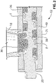
- FIG. 2 is an axial cross-sectional view of feeding portion 12 of apparatus 10.
- FIG. 2 also shows plastic material 36 being fed from hopper 18 toward melting portion 14 along flow direction F by propeller 20.
- Plastic material 36 may be in particulate form when it is fed from hopper 18.
- pellets or pieces of material can easily be caught between the auger flute and feed area wall.
- Propeller 20 e.g., auger
- Propeller 20 may comprise one or more notches 38 formed into one or more flutes 40 of propeller 20.
- Notch 38 may comprise a circumferential groove formed into propeller 20 near the feed area of hopper 18. Notch 38 may substantially prevent plastic material 36 from getting pinched between propeller 20 and feeding barrel 21 during feeding of the plastic material 36. This may also contribute to the reduced torque requirement for turning propeller 20 during feeding of the plastic material 36. Notch 38 may be larger than largest particle size expected to be fed into apparatus 10. Hence, particles (pellets) that end up in a position where they would normally be sheared between propeller 20 and feeding barrel 21 instead fall into notch 38 and either slide into feeding barrel 21 or are pushed back out of the way.
- Notch 38 may take away some of the pushing action provided by propeller 20 but the cross-sectional diameter of feeding barrel 21 may be made large enough so that the particles in notch 38 may still get pushed forward by the particles interacting with the flute(s) 40 of propeller 20 behind notch 38.
- FIG. 3a is a side view of an exemplary propeller 20 of apparatus 10
- FIG. 3b is a perspective view of the exemplary propeller 20 of apparatus 10.
- propeller 20 e.g., auger
- propeller 20 may comprise one or more notches 38 formed into one or more flutes 40 of propeller 20.
- propeller 20 e.g., auger
- propeller 20 may have a relatively high thread pitch with relatively thin flights as necessary to facilitate suitable propelling of plastic material 36.
- Propeller 20 may be disposed inside feeding barrel 21 for propelling plastic material 36 forward and toward melting chamber 28.
- FIG. 4a is a side view of melting insert 30 of apparatus 10.
- Melting insert 30 may be configured for insertion into melting chamber 28 of melting portion 14.
- Melting insert 30 may comprise outer surface 42 configured to at least partially make contact with inner surface 26 of melting barrel 24.
- outer surface 42 may be dimensioned and shaped to be in contact with inner surface 26 of melting barrel 24.
- melting chamber 28 may have a substantially circular cross-section and an outer diameter of insert 30 may be substantially the same as the cross-sectional diameter of melting barrel 24.
- Outer surface 42 of melting insert 30 may comprise one or more open-ended channels 44 formed therein and extending at least to some extent in a flow direction (e.g., along axis A) of melting barrel 24.
- the one or more channels 44 and inner surface 26 of melting barrel 24 may define corresponding one or more through flow passages for delivering material 36 toward output die 16.
- the at least partial contact between inner surface 26 (see FIG. 1 ) of melting barrel 24 and outer surface 42 of melting insert 30 may permit heat to be transferred conductively from melting barrel 24 into melting insert 30.
- direct contact between inner surface 26 of melting barrel 24 and outer surface 42 of melting insert 30 may provide a direct conductive heat transfer path between melting barrel 24 and insert 30.
- Plastic materials alsowise referred herein as "plastic" typically have very low thermal conductivity, making it difficult to melt such materials. Heating time must be relatively long in proportion to the cross-section of the plastic volume being heated to allow acceptable heat distribution. In melting a flow of plastic in an extrusion system, the heating time generally translates to the length (in the flow direction) along which heat is input (e.g. heated auger or barrel).
- the length required may also depend on other factors such as the flow rate of the plastic and also the rate at which heat is added to the plastic.
- flow speed and rates can be limited by the L/D ratio. Higher L/D may allow for more heat to be added along the length of the barrel but flow resistance due to the increased length of tube or barrel can lower output pressure and flow rate for a given drive speed, force and diameter.
- melting insert 30 may, in some embodiments, contribute to a reduced torque requirement for propeller 20 due to reduced resistance to flow of material for a given L/D ratio and flow rate.
- melting insert 30 may comprise a plurality open-ended channels 44 of relatively small cross-sectional diameters (i.e., compared to the cross-sectional diameter of melting chamber 28) in parallel to each other. Accordingly, incoming semi-viscous plastic flow may be directed into smaller, narrow flow(s).
- the plurality of open-ended channels 44 may be circumferentially-distributed around melting insert 30.
- each of channels 44 may provide a L/D ratio equal to or greater than 20.
- apparatus 10 may have an overall L/D ratio (i.e., for feeding portion 12 and melting portion 14) of about six. For example, an L/D ratio of only melting portion 14 may be about three in some embodiments.
- Melting insert 30 may comprise one or more metallic materials or other suitable materials having a relatively good thermal conductivity.
- melting insert 30 may be made from the same material as that of melting barrel 24.
- melting insert 30 may have a substantially solid interior/core so that melting insert 30 may have substantial heat capacity.
- heat may be conducted into material 36 in channels 44 from melting insert 30 and also from melting barrel 24 during steady state operation.
- heat may be transferred to material 36 in channels 44 in substantially all directions that are perpendicular to channels 44 (e.g., and also perpendicular to axis A shown in FIG. 1 ).
- all bounding surfaces of channels 44 may serve as heating surfaces for the plastic material 36 flowing through channels 44.
- Material 36 may flow in channels 44 for at least some length or the entire length of melting portion 14 and may then be recombined and mixed before exiting through output die 16.
- the use of a plurality of channels 44 in parallel may reduce the thermal gradients within material 36 flowing through melting portion 24 and improve the heating efficiency.
- channels 44 may be substantially straight, have a uniform cross section and be aligned with axis A so that they may be parallel to each other.
- channels 44 may have other constructions than those shown herein.
- channels 44 may have varying cross-section(s) along their lengths and may extend in a helical or other manner along melting insert 30.
- Channels 44 may be open-ended so that a first end receive material 36 from melting chamber 28 and a second end may deliver material 36 to output die 16.
- melting insert 30 may have leading end 46 and trailing end 48, where one or both of which may be tapered.
- the shape(s) of leading end 46 and trailing end 48 may be determined by the shape of melting chamber 28.
- the tapered shape of leading end 46 may assist in directing material 36 toward channels 44.
- Leading end 46 of melting insert 30 may also be tapered toward an optional central rod 43 (see e.g. FIGs. 4b and 4c ) disposed inside of melting chamber 28.
- such central rod may be disposed upstream of melting insert 30 in order to form an annular channel inside of melting chamber 28 and into which the plastic material 36 may flow before reaching melting insert 30.
- Such annular channel may also promote heating and melting of plastic material 36 by having plastic material 36 flow closer to inner surface 26 of melting barrel 24.
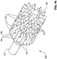
- FIG. 4b is a side view of another exemplary melting insert 30 that may be suitable for use with apparatus 10.
- the melting insert 30 may include a central rod 43, a first portion 45 and a second portion 47.
- the first portion 45 of the melting insert 30 may comprise a leading end 46 that is tapered towards the central rod 43, so that plastic material 36 may flow past the central rod 43 and be directed to channels 44.
- Trailing end 48 may be square (i.e., not be tapered).
- the first portion 45 and the second portion 47 together may form the entire length 49 of channels 44.
- Each of the channels 44 may have a relatively straight path in the first portion 45, and then a helical path in the second portion 47 of the melting insert 30.
- Channels 44 may have constant or varying cross-section(s) along the length of second portion 47, and may extend in a helical or other manner along melting insert 30.
- one or more of channels 44 (or part(s) thereof) may extend along a direction that is substantially parallel or non-parallel to longitudinal axis A (see FIG. 1 ).
- channels 44 may intersect each other in a criss-cross manner (e.g., X-pattern).
- channels 44 may be configured as (e.g., double) helixes.
- channels 44 may intersect and combine with each other.
- one or more of channels 44 may split into two or more channels 44.
- FIG. 4c is a perspective view of the melting insert 30 of FIG. 4b .
- plastic material 36 may be heated so that material 36 may be melted and turn into a viscous liquid due at least in part to the heating and friction provided by melting insert 30.
- One or more of the channels 44 may intersect or criss-cross one another, promoting mixing and enabling more uniform melting of plastic material 36.
- viscous friction associated with the flow of material 36 through the helical channels 44 may generate heat and vary the flow velocity profile, further promoting mixing and uniform melting.
- the helical configuration of the channels 44 may provide an even greater local L/D ratio (e.g., equal to or greater than about 20) for improved frictional heating and mixing, without requiring a large overall length 49 of the melting insert 30.
- FIG. 4d is a transverse cross-sectional view of the melting insert 30 of FIG. 4b along line A-A
- Channels 44 may have uniform or different cross-sectional shape(s). As illustrated, each channel 44 may be defined by lower surface 50 having a substantially arcuate or "U" shaped cross-sectional profile. In some embodiment, lower surface 50 may extend inwardly towards the center of the melting insert 30. In various embodiments, alternate channels 44 may have a greater radial depth toward the center of melting insert 30 compared to adjacent channels 44.
- FIG. 5a is a cross-sectional view of a melting chamber of an apparatus for extruding plastic material without a melting insert
- FIG. 5b is an analogous cross-section view of melting chamber 28 of apparatus 10 with melting insert 30, taken along line 5-5 in FIG. 1 .
- plastic material 36 is divided into multiple, parallel heated flows, shown in FIG. 5b .
- the L/D ratio of each channel 44 is higher than the single, larger flow of the melting chamber shown in FIG. 5a without melting insert 30.
- the length, shape, and diameter of the melting insert 30 as well as the number, size, shape, etc. of channels 44 are parameters of operation and may be different than those shown depending on the specific application and process parameters.
- Melting insert 30 may split the flow of material 36 into several flows in parallel allowing for an increased L/D ratio, with a considerably small overall length of melting portion 14 (and consequently of apparatus 10) in comparison with a single channel of comparable cross-sectional area and L/D ratio.
- the overall flow volume inside melting chamber 28 may be decreased due to the presence of melting insert 30 but the thermal gradients across material 36 in channels 44 may also be decreased in comparison with the melting chamber shown in FIG. 5a . Accordingly, at steady state, the use of melting insert 30 may, in some embodiments, result in faster melting of material 36 while requiring comparable or less energy input than would otherwise be required without the use of melting insert 30.
- inner surface 26 which defines melting chamber 28 may have a substantially circular cross-sectional profile.
- outer surface 42 may correspondingly follow the same profile so that one or more of the intermediate surface portions 42 defined between the circumferentially-distributed channels 44 may be in contact with inner surface 26 when insert 30 is disposed inside melting chamber 28.
- Channels 44 may comprise open-ended grooves formed in outer surface 42 of insert.
- One or more of channels 44 may have a partially circular, square or other suitable cross-sectional shape.
- each channel 44 may be defined by lower surface 50 having a substantially arcuate cross-sectional profile.
- FIG. 6a is a top view of another exemplary apparatus 10 for extruding suitable plastic material 36 with heater 22 not being shown.
- Apparatus 10 of FIG. 6A may comprise melting insert 30 as illustrated in FIGS. 4b-4d or some other configuration of melting insert 30.
- FIG. 6b is a cross-sectional view of the apparatus 10 of FIG. 6a , taken along line B-B in FIG. 6a .
- the apparatus 10 may comprise feed opening 11, through which plastic material 36 may be deposited into feeding barrel 21.
- the apparatus 10 may include a drive motor 15 coupled to propeller 20 via one or more gears 13. Gears 13 and drive motor 15 may be utilized to actuate and turn the propeller 20, which in turn force and compress raw plastic material 36 down the feeding barrel 21.
- apparatus 10 of FIG. 6a may comprise a nozzle assembly 17 including screen 32 and output die 16.
- the nozzle assembly 17 may be in communication with melting portion 14 to facilitate extrusion of melted material.
- output die 16 may extrude or produce the melted material in a direction substantially perpendicular to the longitudinal axis A of melting portion 14.
- FIG. 6c is a side view of some components of the apparatus in FIG. 6a .
- a central rod 43 of melting insert 30 may extend to an end of propeller 20 to facilitate movement of plastic materials 36 into channels 44.
- Such central rod 43 may be in accordance with an example useful for understanding the invention integrally formed with or in accordance with an embodiment separate from melting insert 30 and disposed at or near leading end 46 of melting insert 30.
- an annular channel may be formed between inner surface 26 of melting barrel 24 and peripheral surface of central rod 43, the annular channel may be substantially inside the melting chamber 28.
- the plastic material 36 may flow into the annual channel before reaching channels 44 of the melting insert 30.
- Such annular channel may promote heating and melting of plastic material 36 by having plastic material 36 flow closer to inner surface 26 of melting barrel 24.
- a user may manually start the operation of extrusion apparatus 10, or the apparatus 10 may be started automatically based on a timer or software running in a suitable controller (not shown).
- the controller of apparatus 10 may monitor the temperature(s) on various parts of the apparatus 10. Once the proper temperature for melting the plastic material 36 has been reached in melting portion 14, the controller may (e.g., after a suitable delay) cause propeller 20 to start pushing material 36 toward melting portion 14.
- Material 36 may be received in propeller 20 via hopper 18, pushed into melting chamber 28 via propeller 20, melted inside melting chamber 28 with the assistance of melting insert 30 and delivered to output die 16 via channels 44 of melting insert 30.
- Feeding portion 12 may receive material 36 from hopper 18 and propeller 20 may push or propel material 36 forward into melting portion 14. While within feeding portion 12, material 36 may substantially stay in its solid form as feeding portion 12 may not be significantly heated and may also be thermally insulated from melting portion 14 of apparatus 10. Accordingly, feeding barrel 21 and propeller 20 may remain relatively cool in comparison with melting portion 14 since propeller 20 may not extend into melting portion 14 and may not interact with significant amounts of melted material. Melting portion 14 may be maintained at the required temperature for melting material 36 while being insulated via thermal insulator 34 from the feeding portion 12 so that conductive heat loss may be reduced and the main loss of heat may be via the extrudate exiting output die 16.
- material 36 may be heated by heater 22 via melting barrel 24, while being pushed further by incoming material 36 from feeding portion 12 and forced into channels 44 of melting insert 30.
- semi-viscous (and/or still somewhat solid) material 36 is divided into separate and parallel smaller flows via channels 44 of melting insert 30.
- material 36 may be heated so that material 36 may be melted and turn into a viscous liquid due at least in part to the heating and friction provided by melting insert 30.
- Smaller channels 44 may have a higher surface area/volume, resulting in more viscous drag on the flow of material 36 from the enclosing surface area. Viscous friction associated with the flow of material 36 through channels 44 may generate heat and vary the flow velocity profile thereby promoting mixing and helping to produce uniform melting of material 36.
- Channels 44 of melting insert 30 may be configured to provide adequate L/D ratio (e.g., equal to or greater than about 20) for frictional heating and mixing required for uniform melting of material 36 without requiring a large overall length due to the parallel arrangement of channels 44.
- propeller 20 may only serve to propel or push material 36 in the feeding portion 12 toward the melting portion 14 without having propeller 20 physically extending into melting portion 14. This may allow for an overall size of apparatus 10 to be kept relatively small while still permitting practical and effective small scale extrusion operations.
- the melted material 36 may then be recombined or mixed into a single flow just before exiting output die 16 in the form of an extrudate. Additional particle material 36 may be added by the user as needed via hopper 18 during operation of the apparatus 10.
- FIG. 7 illustrates a process of pulling on an extrudate being output via output die 16 of apparatus 10.
- the extrudate may be subjected to a stretching and cooling process via puller 35 or other suitable mechanisms for pulling the plastic extrudate.
- Existing extrusion systems typically output mostly solid extrudate, while the pulling disclosed herein may be used to control the dimensional accuracy of the extrudate by pulling the extrudate while the extrudate is still in the form of a viscous liquid.
- existing systems typically maintain tension, to track whatever the extruder is pushing out so it doesn't curve, bulge or stretch.
- puller 35 may only need to maintain a constant drawing speed to relieve the constant built up pressure and stretch material 36 while it cools to its final size.
- the constant speed of puller 35 may be delivered by stepper motor or other suitable means of applying the drawing force on the extrudate. Changes to extrudate diameter may then be achieved by changing the speed of puller 35 via suitable control software rather than having to adjust die size, and possibly the tensioning system as is done in existing systems.
- Puller 35 may continuously draw melted material 36 from output die 16 through a cooling stage.
- the size of output die 16 may be larger than the desired final diameter of the extrudate and material 36 may be continuously pulled through a cooling medium to elongate while cooling.
- the cooling medium may be air, water, or any other suitable fluid, and can be still or in motion to obtain free or forced convection.
- Puller 35 may comprise a pair of relatively soft, high friction rollers configured to grab the extrudate and draw it out at a constant rate.
- a suitable mechanism may control the compressive force between the rollers to maintain a suitable gripping force without deforming, squishing or otherwise damaging the extrudate.
- the drawing speed of puller 35 may affect polymer elongation, which may consequently affect tensile properties and the resulting diameter of extrudate. Assuming constant material properties and throughput rate at output die 16, a constant draw rate may provide constant extrudate diameter and physical and mechanical properties. Material 36 may emerge from output die 16 as a viscous liquid (e.g., above the polymer's flow point) at a larger, pre-form diameter. Material 36 may then be pulled straight out from die 16 and stretched to the correct diameter as it cools.
- the forced elongation during cooling may overrule inconsistencies caused by nozzle drag and environmental surroundings. Constant stretching of material 36 as it exits output die 16 may also reduce or eliminate the effect of die swell. For a given volume flow rate at output die 16, the drawing speed may control elongation and diameter of the resulting extrudate. For example, for a given throughput, a faster pull may result in a thinner and more elongated extrudate thereby allowing for a range of extrudate diameters to be obtained from the same output die 16.
- Elongation of polymers can also stretch and align the molecular chains, resulting in a more flexible, less brittle extrudate. Accordingly, pull speed and the diameter of output die 16 may be changed to change the amount of elongation obtained and achieve the same extrudate diameter ranges. Also, changing the size of output die 16 while keeping the other parameters constant may result in getting same elongation at different diameters. The use of this method of cooling while stretching to size may require a relatively consistent melting of material in melting portion 14 and the use of melting insert 30 may help in this regard.
- one or more controllers and/or sensors coupled to various parts of the apparatus 10 in order to measure and control the temperature(s) at the various parts of the apparatus 10 and also control various aspects of operation of apparatus.
- controller may be configured to control the starting and stopping of propeller 20 and optionally also the input torque to propeller 20.
- controller may be configured to control the starting and stopping of puller 35 and optionally also the draw speed of puller 35.
- operation parameters associated with apparatus 10 may vary depending on factors such as the type of material 36 used, heat input, desired throughput and specific configuration of apparatus 10.
- improved melting consistency may permit the implementation of a standardized system where basic parameters may be changed (e.g., input) to adjust properties for different plastics or diameters of extrudate. This may also improve stability of apparatus 10 and reduce the amount of human interaction required to adjust the settings.
- melting insert 30 and melting barrel 24 may be integrally formed in a one-piece structure.
- a direct thermal conduction path may be defined between melting barrel 24 and melting insert 30.
Landscapes
- Engineering & Computer Science (AREA)
- Mechanical Engineering (AREA)
- Physics & Mathematics (AREA)
- Thermal Sciences (AREA)
- Extrusion Moulding Of Plastics Or The Like (AREA)
Claims (10)
- Vorrichtung (10) zum Extrudieren von Kunststoffmaterial, wobei die Vorrichtung (10) Folgendes aufweist:- einen Zuführbereich (12);- einen Schmelzbereich (14), der mit dem Zuführbereich (12) in Verbindung steht und so konfiguriert ist, dass er Wärme in das vom Zuführbereich (12) aufgenommene Material überträgt;- eine Ausgangsdüse (16), die mit dem Schmelzbereich (14) in Verbindung steht, um die Extrusion des von dem Schmelzbereich (14) aufgenommenen Materials zu ermöglichen; und- wobei der Schmelzbereich (14) aufweist:dadurch gekennzeichnet,- einen Schmelzzylinder (24) mit einer inneren Oberfläche (26), die eine Schmelzkammer (28) in Verbindung mit dem Zuführbereich (12) definiert; und- einen Schmelzeinsatz (30) innerhalb der Schmelzkammer (28), wobei der Schmelzeinsatz (30) eine äußere Oberfläche (42) aufweist, wobei die äußere Oberfläche (42) des Schmelzeinsatzes (30) einen oder mehrere offenendige Kanäle (44) aufweist, die darin ausgebildet sind und sich in einer Strömungsrichtung des Schmelzzylinders (24) erstrecken, wobei der eine oder die mehreren Kanäle (44) und die innere Oberfläche (26) des Schmelzzylinders (24) einen oder mehrere entsprechende Durchflusskanäle zum Zuführen von Material zu der Ausgangsdüse (16) definieren,wobei:die Außenfläche (42) des Schmelzeinsatzes (30) zumindest teilweise in Kontakt mit der inneren Oberfläche (26) des Schmelzzylinders (24) ist; oderder eine oder die mehreren offenendigen Kanäle (44) eine Vielzahl von offenendigen Kanälen (44) aufweisen, die durch dazwischenliegende äußere Oberflächenbereiche (42) getrennt sind, die jeweils mit der inneren Oberfläche (26) des Schmelzzylinders (24) zusammenwirken, um einen direkten Wärmeleitungsweg zwischen dem Schmelzzylinder (24) und dem Schmelzeinsatz (30) bereitzustellen;und wobei der Schmelzeinsatz (30) einen massiven Kern und ein sich verjüngendes vorderes Ende (46) aufweist;
dass die Vorrichtung ferner einen thermischen Isolator (34) aufweist, der zwischen dem Zuführbereich (12) und dem Schmelzbereich (14) angeordnet ist. - Vorrichtung nach Anspruch 1,
wobei der Schmelzeinsatz (30) ein sich verjüngendes hinteres Ende (48) aufweist. - Vorrichtung nach einem der Ansprüche 1 und 2,
wobei sich der eine oder die mehreren Kanäle (44) in einer Richtung erstrecken, die im Wesentlichen parallel zur Strömungsrichtung des Schmelzzylinders (24) verläuft. - Vorrichtung nach einem der Ansprüche 1 und 2,
wobei sich der eine oder die mehreren Kanäle (44) entlang jeweiliger Richtungen erstrecken, die nicht parallel zur Strömungsrichtung des Schmelzzylinders (24) sind. - Vorrichtung nach einem der Ansprüche 1 und 2,
wobei sich zwei oder mehr der Kanäle (44) gegenseitig kreuzen. - Vorrichtung nach einem der Ansprüche 1 bis 5,
wobei zwei oder mehr der Kanäle (44) in Umfangsrichtung um den Schmelzeinsatz (30) herum verteilt sind. - Vorrichtung nach einem der Ansprüche 1 bis 6,
wobei der Zuführbereich (12) eine Schnecke (20) aufweist, die vollständig außerhalb des Schmelzbereichs (14) angeordnet ist. - Vorrichtung nach einem der Ansprüche 1 bis 6,
wobei der Zuführbereich (12) einen Propeller (20) zum Zuführen von Material in Richtung des Schmelzbereichs (14) aufweist, wobei der Propeller (20) vollständig außerhalb des Schmelzbereichs (14) angeordnet ist. - Vorrichtung nach Anspruch 8,
wobei der Propeller eine Schnecke (20) aufweist. - Vorrichtung nach einem der Ansprüche 1 bis 6,wobei der Zuführbereich (12) eine Schnecke (20) aufweist; undwobei der Schmelzbereich (14) eine Stange (43) aufweist, die sich zwischen dem Schmelzeinsatz (30) und der Schnecke (20) erstreckt, wobei die Stange (43) und der Schmelzzylinder (24) einen ringförmigen Durchgang zwischen der Schnecke (20) und dem Schmelzeinsatz (30) definieren und die Stange (43) von dem Schmelzeinsatz (30) getrennt ist.
Applications Claiming Priority (3)
| Application Number | Priority Date | Filing Date | Title |
|---|---|---|---|
| US201461941689P | 2014-02-19 | 2014-02-19 | |
| CA2843392A CA2843392C (en) | 2014-02-19 | 2014-02-20 | Apparatus for extruding plastic materials |
| PCT/CA2015/000099 WO2015123757A1 (en) | 2014-02-19 | 2015-02-18 | Apparatus for extruding plastic materials |
Publications (3)
| Publication Number | Publication Date |
|---|---|
| EP3107707A1 EP3107707A1 (de) | 2016-12-28 |
| EP3107707A4 EP3107707A4 (de) | 2017-11-22 |
| EP3107707B1 true EP3107707B1 (de) | 2022-04-20 |
Family
ID=53873621
Family Applications (1)
| Application Number | Title | Priority Date | Filing Date |
|---|---|---|---|
| EP15752829.0A Active EP3107707B1 (de) | 2014-02-19 | 2015-02-18 | Vorrichtung zum extrudieren von kunststoffen |
Country Status (5)
| Country | Link |
|---|---|
| US (1) | US10744697B2 (de) |
| EP (1) | EP3107707B1 (de) |
| AU (1) | AU2015221368B2 (de) |
| CA (2) | CA2843392C (de) |
| WO (1) | WO2015123757A1 (de) |
Families Citing this family (13)
| Publication number | Priority date | Publication date | Assignee | Title |
|---|---|---|---|---|
| HUE048954T2 (hu) * | 2017-11-07 | 2020-09-28 | W Mueller Gmbh | Gyûrûs elosztó extrúziós tömlõfejhez, tömlõ alakú idomdarab hõre lágyuló mûanyagból történõ elõállításához |
| IT201800001715A1 (it) * | 2018-01-24 | 2019-07-24 | Gimac Di Maccagnan Giorgio | Dispositivo di estrusione |
| CN110962323A (zh) * | 2018-09-29 | 2020-04-07 | 台山市昊富美电器有限公司 | 一种带过滤装置的薄膜管热成型设备 |
| FI128422B (en) | 2019-01-11 | 2020-04-30 | Teknologian Tutkimuskeskus Vtt Oy | Single screw extruders and extrusion procedure |
| CN110027185B (zh) * | 2019-03-01 | 2020-11-24 | 义乌市倩飞科技有限公司 | 一种采用相反轨迹截质的混凝土养护膜生产设备 |
| CN110815758A (zh) * | 2019-12-16 | 2020-02-21 | 安徽三绿实业有限公司 | 一种3d打印耗材出丝用干燥处理装置 |
| CN111993654B (zh) * | 2020-08-07 | 2022-03-29 | 合肥翰骏环保技术开发有限公司 | 一种塑钢型材生产用挤出机上料结构 |
| JP2022083576A (ja) * | 2020-11-25 | 2022-06-06 | 信越ポリマー株式会社 | 押出成形機のフィルタ装置 |
| CN112571752B (zh) * | 2020-12-10 | 2025-09-05 | 广东仕诚塑料机械有限公司 | 一种多层共挤薄膜的塑料挤出装置 |
| CN114750392B (zh) * | 2021-01-11 | 2024-05-28 | 山东智华生物科技研究院有限公司 | 降密度生物全降解薄膜挤出成型机 |
| CN114986842B (zh) * | 2022-04-20 | 2024-01-26 | 上海伊川水塑料制品有限公司 | 一种用于聚全氟乙丙烯管材的上料装置 |
| CN115805693B (zh) * | 2022-12-08 | 2025-07-15 | 台州市万吉精密机械有限公司 | 改进型注塑机螺杆料筒装置 |
| CN119779815A (zh) * | 2025-01-03 | 2025-04-08 | 如东天泰纺织有限公司 | 一种纺织布料质量检测装置及其方法 |
Citations (4)
| Publication number | Priority date | Publication date | Assignee | Title |
|---|---|---|---|---|
| DE7013580U (de) * | 1969-04-18 | 1970-07-16 | Montedison Spa | Verbesserter extruder zur vermeidung von marmorierungseffekten bei extrudierten kunststoffgegenstaenden. |
| US3762692A (en) * | 1970-06-23 | 1973-10-02 | Barmag Barmer Maschf | Screw extruder for thermoplastic melts with temperature equalizing head |
| US3989434A (en) * | 1975-10-29 | 1976-11-02 | Mcdowell-Wellman Engineering Company | Blending and molding means |
| US7032843B1 (en) * | 2003-04-24 | 2006-04-25 | Westland Corporation U.S.A., Inc. | Mixing nozzle |
Family Cites Families (26)
| Publication number | Priority date | Publication date | Assignee | Title |
|---|---|---|---|---|
| US2895167A (en) | 1954-06-09 | 1959-07-21 | Mario Maccaferri | Filtering liner for barrels of extrusion machines |
| US2896253A (en) | 1957-01-17 | 1959-07-28 | Du Pont | Screw for handling thermoplastic resins |
| GB977473A (en) | 1960-06-01 | 1964-12-09 | Kalle Ag | Improvements in and relating to the manufacture of biaxially stretched tubular films |
| US3253302A (en) | 1960-12-08 | 1966-05-31 | Phillips Petroleum Co | Nozzle for injection molding machine |
| US3284848A (en) | 1964-09-23 | 1966-11-15 | Reynolds Metals Co | Extruding apparatus |
| US3555603A (en) | 1968-08-30 | 1971-01-19 | Fmc Corp | Tubular film manufacturing apparatus |
| DE2017580A1 (de) | 1970-04-13 | 1971-10-28 | Barmag Barmer Maschf | Schneckenstrangpresse mit einer eingängigen, eine erhöhte Scherung bewirkenden Schnecke |
| US3730492A (en) | 1971-06-17 | 1973-05-01 | Union Carbide Corp | Mixing of thermoplastic materials |
| US3710983A (en) * | 1971-08-20 | 1973-01-16 | R Ricciardi | Plural auger material handling blending system |
| DE2161067C2 (de) | 1971-12-09 | 1973-09-20 | Fa. Werner & Pfleiderer, 7000 Stuttgart | Vorrichtung zum Abkühlen von aus einem Extruder austretenden Kunststoff strängen |
| US3897937A (en) | 1973-08-30 | 1975-08-05 | A Paul Limbach | Extruder screw |
| CH615113A5 (de) | 1976-04-29 | 1980-01-15 | Sulzer Ag | |
| US4249877A (en) * | 1979-03-26 | 1981-02-10 | Machen James F | High-speed direct-drive extruder |
| US4289727A (en) | 1979-12-19 | 1981-09-15 | Mobil Oil Corporation | Method for extrusion of tubular films |
| NL8001053A (nl) * | 1980-02-21 | 1981-09-16 | Stamicarbon | Werkwijze voor het vormgeven van kunststoffen. |
| US4425044A (en) | 1981-10-21 | 1984-01-10 | Union Carbide Corporation | Mixer heads for polyolefin extruders |
| US4478516A (en) | 1982-09-30 | 1984-10-23 | Milton Kessler | Apparatus for mixing and blending constituents of a flow of thermoplastics material |
| US4501498A (en) * | 1983-12-05 | 1985-02-26 | Luwa Corporation | Method and apparatus for extruding thermoplastic material |
| DE3915603C1 (de) | 1989-05-12 | 1990-03-15 | Basf Ag, 6700 Ludwigshafen, De | |
| US5098267A (en) | 1990-06-22 | 1992-03-24 | Union Carbide Industrial Gases Technology Corporation | Apparatus and method for producing and molding structural foam |
| JP2920105B2 (ja) | 1996-02-26 | 1999-07-19 | 中ノ瀬 一徳 | 廃プラスチック再生方法及び再生機 |
| US6454454B1 (en) * | 1996-04-30 | 2002-09-24 | Robert A. Barr | Polymer melting and extruding apparatus with linear downstream threads |
| DE19637063A1 (de) * | 1996-09-12 | 1998-03-19 | Werner & Pfleiderer | Extruder für die Herstellung von Kunststoffgranulat |
| US6719935B2 (en) | 2001-01-05 | 2004-04-13 | Howmedica Osteonics Corp. | Process for forming bioabsorbable implants |
| US6712495B2 (en) * | 2001-11-20 | 2004-03-30 | E. I. Du Pont De Nemours And Company | Mixing apparatus |
| CA2442780C (en) | 2002-12-13 | 2007-12-11 | Sulzer Chemtech Ag | A static mixer for high-viscosity media |
-
2014
- 2014-02-20 CA CA2843392A patent/CA2843392C/en active Active
-
2015
- 2015-02-18 AU AU2015221368A patent/AU2015221368B2/en active Active
- 2015-02-18 WO PCT/CA2015/000099 patent/WO2015123757A1/en not_active Ceased
- 2015-02-18 EP EP15752829.0A patent/EP3107707B1/de active Active
- 2015-02-18 US US15/119,526 patent/US10744697B2/en active Active
- 2015-02-18 CA CA2939271A patent/CA2939271A1/en not_active Abandoned
Patent Citations (4)
| Publication number | Priority date | Publication date | Assignee | Title |
|---|---|---|---|---|
| DE7013580U (de) * | 1969-04-18 | 1970-07-16 | Montedison Spa | Verbesserter extruder zur vermeidung von marmorierungseffekten bei extrudierten kunststoffgegenstaenden. |
| US3762692A (en) * | 1970-06-23 | 1973-10-02 | Barmag Barmer Maschf | Screw extruder for thermoplastic melts with temperature equalizing head |
| US3989434A (en) * | 1975-10-29 | 1976-11-02 | Mcdowell-Wellman Engineering Company | Blending and molding means |
| US7032843B1 (en) * | 2003-04-24 | 2006-04-25 | Westland Corporation U.S.A., Inc. | Mixing nozzle |
Also Published As
| Publication number | Publication date |
|---|---|
| CA2939271A1 (en) | 2015-08-27 |
| WO2015123757A8 (en) | 2016-09-22 |
| EP3107707A4 (de) | 2017-11-22 |
| EP3107707A1 (de) | 2016-12-28 |
| CA2843392C (en) | 2020-08-25 |
| WO2015123757A1 (en) | 2015-08-27 |
| US20170008214A1 (en) | 2017-01-12 |
| CA2843392A1 (en) | 2015-08-19 |
| US10744697B2 (en) | 2020-08-18 |
| AU2015221368A1 (en) | 2016-09-08 |
| AU2015221368B2 (en) | 2017-12-07 |
Similar Documents
| Publication | Publication Date | Title |
|---|---|---|
| EP3107707B1 (de) | Vorrichtung zum extrudieren von kunststoffen | |
| US11220022B2 (en) | Extruder screw having paths within the screw, extruder, and extrusion method | |
| US3431599A (en) | Extrusion method and apparatus | |
| EP0456230B1 (de) | Extruderschnecke | |
| US20210154906A1 (en) | Extruder screw having paths within the screw, extruder, and extrusion method | |
| CN105142876B (zh) | 单螺杆塑化机、一组设备和用于塑化输出物的方法 | |
| US20160332331A1 (en) | Extruder screw, extruder, and extrusion method | |
| JP2018503546A (ja) | 射出成形システムおよび部品製造方法 | |
| CN101767430A (zh) | 集密炼、喂料、挤出功能为一体的组合式机组 | |
| CN204869587U (zh) | 一种塑料粒成型的双螺杆挤出装置 | |
| WO2010053576A1 (en) | Combined screw design and heating mechanism for low shear resins | |
| CN202062635U (zh) | 差速锥形双螺杆挤出机 | |
| CN108437400A (zh) | 一种两级七段式高转速高产pp挤出螺杆 | |
| CN102228818A (zh) | 转子三角形排列的锥形三转子连续混炼机组 | |
| CN202212120U (zh) | 转子三角形排列的锥形三转子连续混炼机组 | |
| CN202155160U (zh) | 锥形双转子连续混炼机组 | |
| CN106536154A (zh) | 包括带有螺纹的筒的挤出机 | |
| CN201633185U (zh) | 一字型排列的锥形三螺杆挤出机 | |
| CN102275285A (zh) | 螺杆三角形排列的差速锥形三螺杆挤出机 | |
| CN201538027U (zh) | 一种大型高分子制品挤出成型装置 | |
| CN204936148U (zh) | 一种涤纶丝加工用螺杆挤压机 | |
| CN102039657A (zh) | 一种大型高分子制品挤出成型装置及工艺 | |
| JPH05220818A (ja) | 単軸押出機 | |
| CN205871133U (zh) | 具有多种螺旋的螺杆挤出机 | |
| CN105082512B (zh) | 熔体挤出压力驱动具有内外螺棱转子的均流方法及装置 |
Legal Events
| Date | Code | Title | Description |
|---|---|---|---|
| PUAI | Public reference made under article 153(3) epc to a published international application that has entered the european phase |
Free format text: ORIGINAL CODE: 0009012 |
|
| STAA | Information on the status of an ep patent application or granted ep patent |
Free format text: STATUS: REQUEST FOR EXAMINATION WAS MADE |
|
| 17P | Request for examination filed |
Effective date: 20160919 |
|
| AK | Designated contracting states |
Kind code of ref document: A1 Designated state(s): AL AT BE BG CH CY CZ DE DK EE ES FI FR GB GR HR HU IE IS IT LI LT LU LV MC MK MT NL NO PL PT RO RS SE SI SK SM TR |
|
| AX | Request for extension of the european patent |
Extension state: BA ME |
|
| RIN1 | Information on inventor provided before grant (corrected) |
Inventor name: OOSTERMAN, JAMES DENNON Inventor name: JOYCE, DAVID MILES Inventor name: KAY, ALEX W. |
|
| DAX | Request for extension of the european patent (deleted) | ||
| A4 | Supplementary search report drawn up and despatched |
Effective date: 20171024 |
|
| RIC1 | Information provided on ipc code assigned before grant |
Ipc: B29C 47/58 20060101ALI20171018BHEP Ipc: B29C 47/36 20060101AFI20171018BHEP Ipc: B29C 47/60 20060101ALI20171018BHEP Ipc: B29C 47/00 20060101ALN20171018BHEP Ipc: B29C 47/66 20060101ALI20171018BHEP Ipc: B29C 47/82 20060101ALI20171018BHEP Ipc: B29C 47/08 20060101ALI20171018BHEP Ipc: B01F 5/06 20060101ALI20171018BHEP Ipc: B29C 47/68 20060101ALI20171018BHEP |
|
| REG | Reference to a national code |
Ref country code: DE Ref legal event code: R079 Ref document number: 602015078356 Country of ref document: DE Free format text: PREVIOUS MAIN CLASS: B29C0047580000 Ipc: B29C0048360000 |
|
| STAA | Information on the status of an ep patent application or granted ep patent |
Free format text: STATUS: EXAMINATION IS IN PROGRESS |
|
| RIC1 | Information provided on ipc code assigned before grant |
Ipc: B29C 48/36 20190101AFI20190118BHEP Ipc: B29C 48/69 20190101ALI20190118BHEP Ipc: B29C 48/25 20190101ALI20190118BHEP Ipc: B01F 5/06 20060101ALI20190118BHEP Ipc: B29C 48/695 20190101ALI20190118BHEP |
|
| 17Q | First examination report despatched |
Effective date: 20190201 |
|
| GRAP | Despatch of communication of intention to grant a patent |
Free format text: ORIGINAL CODE: EPIDOSNIGR1 |
|
| STAA | Information on the status of an ep patent application or granted ep patent |
Free format text: STATUS: GRANT OF PATENT IS INTENDED |
|
| INTG | Intention to grant announced |
Effective date: 20210928 |
|
| GRAS | Grant fee paid |
Free format text: ORIGINAL CODE: EPIDOSNIGR3 |
|
| GRAA | (expected) grant |
Free format text: ORIGINAL CODE: 0009210 |
|
| STAA | Information on the status of an ep patent application or granted ep patent |
Free format text: STATUS: THE PATENT HAS BEEN GRANTED |
|
| AK | Designated contracting states |
Kind code of ref document: B1 Designated state(s): AL AT BE BG CH CY CZ DE DK EE ES FI FR GB GR HR HU IE IS IT LI LT LU LV MC MK MT NL NO PL PT RO RS SE SI SK SM TR |
|
| REG | Reference to a national code |
Ref country code: GB Ref legal event code: FG4D |
|
| REG | Reference to a national code |
Ref country code: CH Ref legal event code: EP |
|
| REG | Reference to a national code |
Ref country code: IE Ref legal event code: FG4D |
|
| REG | Reference to a national code |
Ref country code: DE Ref legal event code: R096 Ref document number: 602015078356 Country of ref document: DE |
|
| REG | Reference to a national code |
Ref country code: AT Ref legal event code: REF Ref document number: 1484839 Country of ref document: AT Kind code of ref document: T Effective date: 20220515 |
|
| REG | Reference to a national code |
Ref country code: LT Ref legal event code: MG9D |
|
| REG | Reference to a national code |
Ref country code: NL Ref legal event code: MP Effective date: 20220420 |
|
| REG | Reference to a national code |
Ref country code: AT Ref legal event code: MK05 Ref document number: 1484839 Country of ref document: AT Kind code of ref document: T Effective date: 20220420 |
|
| PG25 | Lapsed in a contracting state [announced via postgrant information from national office to epo] |
Ref country code: NL Free format text: LAPSE BECAUSE OF FAILURE TO SUBMIT A TRANSLATION OF THE DESCRIPTION OR TO PAY THE FEE WITHIN THE PRESCRIBED TIME-LIMIT Effective date: 20220420 |
|
| PG25 | Lapsed in a contracting state [announced via postgrant information from national office to epo] |
Ref country code: SE Free format text: LAPSE BECAUSE OF FAILURE TO SUBMIT A TRANSLATION OF THE DESCRIPTION OR TO PAY THE FEE WITHIN THE PRESCRIBED TIME-LIMIT Effective date: 20220420 Ref country code: PT Free format text: LAPSE BECAUSE OF FAILURE TO SUBMIT A TRANSLATION OF THE DESCRIPTION OR TO PAY THE FEE WITHIN THE PRESCRIBED TIME-LIMIT Effective date: 20220822 Ref country code: NO Free format text: LAPSE BECAUSE OF FAILURE TO SUBMIT A TRANSLATION OF THE DESCRIPTION OR TO PAY THE FEE WITHIN THE PRESCRIBED TIME-LIMIT Effective date: 20220720 Ref country code: LT Free format text: LAPSE BECAUSE OF FAILURE TO SUBMIT A TRANSLATION OF THE DESCRIPTION OR TO PAY THE FEE WITHIN THE PRESCRIBED TIME-LIMIT Effective date: 20220420 Ref country code: HR Free format text: LAPSE BECAUSE OF FAILURE TO SUBMIT A TRANSLATION OF THE DESCRIPTION OR TO PAY THE FEE WITHIN THE PRESCRIBED TIME-LIMIT Effective date: 20220420 Ref country code: GR Free format text: LAPSE BECAUSE OF FAILURE TO SUBMIT A TRANSLATION OF THE DESCRIPTION OR TO PAY THE FEE WITHIN THE PRESCRIBED TIME-LIMIT Effective date: 20220721 Ref country code: FI Free format text: LAPSE BECAUSE OF FAILURE TO SUBMIT A TRANSLATION OF THE DESCRIPTION OR TO PAY THE FEE WITHIN THE PRESCRIBED TIME-LIMIT Effective date: 20220420 Ref country code: ES Free format text: LAPSE BECAUSE OF FAILURE TO SUBMIT A TRANSLATION OF THE DESCRIPTION OR TO PAY THE FEE WITHIN THE PRESCRIBED TIME-LIMIT Effective date: 20220420 Ref country code: BG Free format text: LAPSE BECAUSE OF FAILURE TO SUBMIT A TRANSLATION OF THE DESCRIPTION OR TO PAY THE FEE WITHIN THE PRESCRIBED TIME-LIMIT Effective date: 20220720 Ref country code: AT Free format text: LAPSE BECAUSE OF FAILURE TO SUBMIT A TRANSLATION OF THE DESCRIPTION OR TO PAY THE FEE WITHIN THE PRESCRIBED TIME-LIMIT Effective date: 20220420 |
|
| PG25 | Lapsed in a contracting state [announced via postgrant information from national office to epo] |
Ref country code: RS Free format text: LAPSE BECAUSE OF FAILURE TO SUBMIT A TRANSLATION OF THE DESCRIPTION OR TO PAY THE FEE WITHIN THE PRESCRIBED TIME-LIMIT Effective date: 20220420 Ref country code: PL Free format text: LAPSE BECAUSE OF FAILURE TO SUBMIT A TRANSLATION OF THE DESCRIPTION OR TO PAY THE FEE WITHIN THE PRESCRIBED TIME-LIMIT Effective date: 20220420 Ref country code: LV Free format text: LAPSE BECAUSE OF FAILURE TO SUBMIT A TRANSLATION OF THE DESCRIPTION OR TO PAY THE FEE WITHIN THE PRESCRIBED TIME-LIMIT Effective date: 20220420 Ref country code: IS Free format text: LAPSE BECAUSE OF FAILURE TO SUBMIT A TRANSLATION OF THE DESCRIPTION OR TO PAY THE FEE WITHIN THE PRESCRIBED TIME-LIMIT Effective date: 20220820 |
|
| REG | Reference to a national code |
Ref country code: DE Ref legal event code: R097 Ref document number: 602015078356 Country of ref document: DE |
|
| PG25 | Lapsed in a contracting state [announced via postgrant information from national office to epo] |
Ref country code: SM Free format text: LAPSE BECAUSE OF FAILURE TO SUBMIT A TRANSLATION OF THE DESCRIPTION OR TO PAY THE FEE WITHIN THE PRESCRIBED TIME-LIMIT Effective date: 20220420 Ref country code: SK Free format text: LAPSE BECAUSE OF FAILURE TO SUBMIT A TRANSLATION OF THE DESCRIPTION OR TO PAY THE FEE WITHIN THE PRESCRIBED TIME-LIMIT Effective date: 20220420 Ref country code: RO Free format text: LAPSE BECAUSE OF FAILURE TO SUBMIT A TRANSLATION OF THE DESCRIPTION OR TO PAY THE FEE WITHIN THE PRESCRIBED TIME-LIMIT Effective date: 20220420 Ref country code: EE Free format text: LAPSE BECAUSE OF FAILURE TO SUBMIT A TRANSLATION OF THE DESCRIPTION OR TO PAY THE FEE WITHIN THE PRESCRIBED TIME-LIMIT Effective date: 20220420 Ref country code: DK Free format text: LAPSE BECAUSE OF FAILURE TO SUBMIT A TRANSLATION OF THE DESCRIPTION OR TO PAY THE FEE WITHIN THE PRESCRIBED TIME-LIMIT Effective date: 20220420 Ref country code: CZ Free format text: LAPSE BECAUSE OF FAILURE TO SUBMIT A TRANSLATION OF THE DESCRIPTION OR TO PAY THE FEE WITHIN THE PRESCRIBED TIME-LIMIT Effective date: 20220420 |
|
| PLBE | No opposition filed within time limit |
Free format text: ORIGINAL CODE: 0009261 |
|
| STAA | Information on the status of an ep patent application or granted ep patent |
Free format text: STATUS: NO OPPOSITION FILED WITHIN TIME LIMIT |
|
| 26N | No opposition filed |
Effective date: 20230123 |
|
| PG25 | Lapsed in a contracting state [announced via postgrant information from national office to epo] |
Ref country code: AL Free format text: LAPSE BECAUSE OF FAILURE TO SUBMIT A TRANSLATION OF THE DESCRIPTION OR TO PAY THE FEE WITHIN THE PRESCRIBED TIME-LIMIT Effective date: 20220420 |
|
| PG25 | Lapsed in a contracting state [announced via postgrant information from national office to epo] |
Ref country code: SI Free format text: LAPSE BECAUSE OF FAILURE TO SUBMIT A TRANSLATION OF THE DESCRIPTION OR TO PAY THE FEE WITHIN THE PRESCRIBED TIME-LIMIT Effective date: 20220420 |
|
| PG25 | Lapsed in a contracting state [announced via postgrant information from national office to epo] |
Ref country code: MC Free format text: LAPSE BECAUSE OF FAILURE TO SUBMIT A TRANSLATION OF THE DESCRIPTION OR TO PAY THE FEE WITHIN THE PRESCRIBED TIME-LIMIT Effective date: 20220420 |
|
| REG | Reference to a national code |
Ref country code: CH Ref legal event code: PL |
|
| REG | Reference to a national code |
Ref country code: BE Ref legal event code: MM Effective date: 20230228 |
|
| PG25 | Lapsed in a contracting state [announced via postgrant information from national office to epo] |
Ref country code: LU Free format text: LAPSE BECAUSE OF NON-PAYMENT OF DUE FEES Effective date: 20230218 Ref country code: LI Free format text: LAPSE BECAUSE OF NON-PAYMENT OF DUE FEES Effective date: 20230228 Ref country code: CH Free format text: LAPSE BECAUSE OF NON-PAYMENT OF DUE FEES Effective date: 20230228 |
|
| REG | Reference to a national code |
Ref country code: IE Ref legal event code: MM4A |
|
| PG25 | Lapsed in a contracting state [announced via postgrant information from national office to epo] |
Ref country code: IT Free format text: LAPSE BECAUSE OF FAILURE TO SUBMIT A TRANSLATION OF THE DESCRIPTION OR TO PAY THE FEE WITHIN THE PRESCRIBED TIME-LIMIT Effective date: 20220420 Ref country code: IE Free format text: LAPSE BECAUSE OF NON-PAYMENT OF DUE FEES Effective date: 20230218 |
|
| PG25 | Lapsed in a contracting state [announced via postgrant information from national office to epo] |
Ref country code: BE Free format text: LAPSE BECAUSE OF NON-PAYMENT OF DUE FEES Effective date: 20230228 |
|
| PG25 | Lapsed in a contracting state [announced via postgrant information from national office to epo] |
Ref country code: BG Free format text: LAPSE BECAUSE OF FAILURE TO SUBMIT A TRANSLATION OF THE DESCRIPTION OR TO PAY THE FEE WITHIN THE PRESCRIBED TIME-LIMIT Effective date: 20220420 |
|
| PG25 | Lapsed in a contracting state [announced via postgrant information from national office to epo] |
Ref country code: BG Free format text: LAPSE BECAUSE OF FAILURE TO SUBMIT A TRANSLATION OF THE DESCRIPTION OR TO PAY THE FEE WITHIN THE PRESCRIBED TIME-LIMIT Effective date: 20220420 |
|
| PG25 | Lapsed in a contracting state [announced via postgrant information from national office to epo] |
Ref country code: CY Free format text: LAPSE BECAUSE OF FAILURE TO SUBMIT A TRANSLATION OF THE DESCRIPTION OR TO PAY THE FEE WITHIN THE PRESCRIBED TIME-LIMIT; INVALID AB INITIO Effective date: 20150218 |
|
| PG25 | Lapsed in a contracting state [announced via postgrant information from national office to epo] |
Ref country code: HU Free format text: LAPSE BECAUSE OF FAILURE TO SUBMIT A TRANSLATION OF THE DESCRIPTION OR TO PAY THE FEE WITHIN THE PRESCRIBED TIME-LIMIT; INVALID AB INITIO Effective date: 20150218 |
|
| PG25 | Lapsed in a contracting state [announced via postgrant information from national office to epo] |
Ref country code: TR Free format text: LAPSE BECAUSE OF FAILURE TO SUBMIT A TRANSLATION OF THE DESCRIPTION OR TO PAY THE FEE WITHIN THE PRESCRIBED TIME-LIMIT Effective date: 20220420 |
|
| PGFP | Annual fee paid to national office [announced via postgrant information from national office to epo] |
Ref country code: GB Payment date: 20260211 Year of fee payment: 12 |
|
| PGFP | Annual fee paid to national office [announced via postgrant information from national office to epo] |
Ref country code: DE Payment date: 20260212 Year of fee payment: 12 |
|
| PGFP | Annual fee paid to national office [announced via postgrant information from national office to epo] |
Ref country code: FR Payment date: 20260211 Year of fee payment: 12 |