EP3107882B1 - Verwendung eines neutralisierungsmittels bei der herstellung von olefin oder styrol - Google Patents
Verwendung eines neutralisierungsmittels bei der herstellung von olefin oder styrol Download PDFInfo
- Publication number
- EP3107882B1 EP3107882B1 EP15752158.4A EP15752158A EP3107882B1 EP 3107882 B1 EP3107882 B1 EP 3107882B1 EP 15752158 A EP15752158 A EP 15752158A EP 3107882 B1 EP3107882 B1 EP 3107882B1
- Authority
- EP
- European Patent Office
- Prior art keywords
- process water
- dilution steam
- separator
- neutralizing agent
- water stripper
- Prior art date
- Legal status (The legal status is an assumption and is not a legal conclusion. Google has not performed a legal analysis and makes no representation as to the accuracy of the status listed.)
- Active
Links
Images

Classifications
-
- C—CHEMISTRY; METALLURGY
- C23—COATING METALLIC MATERIAL; COATING MATERIAL WITH METALLIC MATERIAL; CHEMICAL SURFACE TREATMENT; DIFFUSION TREATMENT OF METALLIC MATERIAL; COATING BY VACUUM EVAPORATION, BY SPUTTERING, BY ION IMPLANTATION OR BY CHEMICAL VAPOUR DEPOSITION, IN GENERAL; INHIBITING CORROSION OF METALLIC MATERIAL OR INCRUSTATION IN GENERAL
- C23F—NON-MECHANICAL REMOVAL OF METALLIC MATERIAL FROM SURFACE; INHIBITING CORROSION OF METALLIC MATERIAL OR INCRUSTATION IN GENERAL; MULTI-STEP PROCESSES FOR SURFACE TREATMENT OF METALLIC MATERIAL INVOLVING AT LEAST ONE PROCESS PROVIDED FOR IN CLASS C23 AND AT LEAST ONE PROCESS COVERED BY SUBCLASS C21D OR C22F OR CLASS C25
- C23F11/00—Inhibiting corrosion of metallic material by applying inhibitors to the surface in danger of corrosion or adding them to the corrosive agent
- C23F11/08—Inhibiting corrosion of metallic material by applying inhibitors to the surface in danger of corrosion or adding them to the corrosive agent in other liquids
- C23F11/18—Inhibiting corrosion of metallic material by applying inhibitors to the surface in danger of corrosion or adding them to the corrosive agent in other liquids using inorganic inhibitors
-
- C—CHEMISTRY; METALLURGY
- C09—DYES; PAINTS; POLISHES; NATURAL RESINS; ADHESIVES; COMPOSITIONS NOT OTHERWISE PROVIDED FOR; APPLICATIONS OF MATERIALS NOT OTHERWISE PROVIDED FOR
- C09K—MATERIALS FOR MISCELLANEOUS APPLICATIONS, NOT PROVIDED FOR ELSEWHERE
- C09K15/00—Anti-oxidant compositions; Compositions inhibiting chemical change
- C09K15/04—Anti-oxidant compositions; Compositions inhibiting chemical change containing organic compounds
- C09K15/20—Anti-oxidant compositions; Compositions inhibiting chemical change containing organic compounds containing nitrogen and oxygen
-
- C—CHEMISTRY; METALLURGY
- C23—COATING METALLIC MATERIAL; COATING MATERIAL WITH METALLIC MATERIAL; CHEMICAL SURFACE TREATMENT; DIFFUSION TREATMENT OF METALLIC MATERIAL; COATING BY VACUUM EVAPORATION, BY SPUTTERING, BY ION IMPLANTATION OR BY CHEMICAL VAPOUR DEPOSITION, IN GENERAL; INHIBITING CORROSION OF METALLIC MATERIAL OR INCRUSTATION IN GENERAL
- C23F—NON-MECHANICAL REMOVAL OF METALLIC MATERIAL FROM SURFACE; INHIBITING CORROSION OF METALLIC MATERIAL OR INCRUSTATION IN GENERAL; MULTI-STEP PROCESSES FOR SURFACE TREATMENT OF METALLIC MATERIAL INVOLVING AT LEAST ONE PROCESS PROVIDED FOR IN CLASS C23 AND AT LEAST ONE PROCESS COVERED BY SUBCLASS C21D OR C22F OR CLASS C25
- C23F15/00—Other methods of preventing corrosion or incrustation
Definitions
- the present invention generally relates to methods for neutralizing acidic streams in an olefin or styrene production plant. More specifically, the invention relates to neutralizing agents for dilution steam systems in the steam cracker process and their use for reducing acid corrosion, minimizing fouling and preventing product contamination.
- Dilution steam is an integral component in the process of production of ethylene, propylene and other byproducts via the pyrolysis of hydrocarbon feedstock. Dilution steam promotes the formation of desired olefins by reducing the hydrocarbon partial pressure in the pyrolysis furnace and it extends the run length of the furnace by slowing the rate of coke deposition.
- the effluent gases must be rapidly cooled, i.e., quenched, in order to prevent the recombination of the reactive olefins into unwanted mixtures of oligomers, polymers and fused aromatic structures.
- quenching process steam is condensed and the resultant hot water is used for heat recovery, the water condensate is cooled further to be used in the quenching process, and a portion of the condensate is processed for re-use as dilution steam.
- This "steam cracking" process (pyrolysis of hydrocarbon feedstock in the presence of dilution steam) also produces a small quantity of less desirable by-products such as carbon monoxide, carbon dioxide, acetaldehyde, and acetic acid.
- the organic acids, acetic acid, propionic acid, formic acid, and to a lesser extent higher C 4 -C 6 organic acids promote corrosion in the aqueous environs of the quench water system, the quench water cleaning vessels (oil/water separator, coalescers, process water stripper) and the dilution steam generator.
- dilution steam system a system which includes the quench water system, oil/water separator, process water stripper, dilution steam generator and dilution steam piping
- sulfur-based acids formed from cracking of sulfur compounds that come with or are added to the hydrocarbon feedstock. These acidic byproducts are neutralized with an alkaline agent.
- the neutralizing agent of choice for dilution steam systems was caustic, NaOH, and this alkalizer is cost-effective provided that the dilution steam generator has sufficient size or design features that prevent the incidental carry-over of sodium ions with the dilution steam.
- Low levels of carry-over of sodium with the dilution steam can cause a greater degree of furnace coking and shorter furnace run length, while high levels of carry-over of sodium can destroy the mechanical properties of the furnace radiant tubes (e.g., sodium embrittlement).
- MEA monoethanolamine
- MEA-acetate salt reacts with acetic acid in dilution steam condensate to form MEA-acetate salt.
- this salt generates a buffered pH condition wherein a small addition of acid does not greatly decrease the pH and a small addition of base does not greatly increase the pH.
- this buffering condition protects against pH shifts into the more corrosive acidic regime, it also requires use of large amounts of MEA to raise the pH into the protective pH range to avoid solubilization of iron oxides and thereby prevent corrosion.
- MEA has a relatively low volatility ratio in a steam boiler
- some amine will carry over with the steam phase in the boiler.
- an amine such as MEA
- the amine goes to the pyrolysis furnace, the amine is cracked to form ammonia and hydrocarbon by-products.
- Ammonia is a contaminant for the ethylene product because it poisons the catalysts that are used to produce polyethylene and ethylene copolymers.
- ethylene product is off-specification due to ammonia, the ethylene product is sent directly to the flaring system until the product is back on specification. Since ammonia is a base, it can raise the pH in the quench water of the dilution steam system.
- US 2006/043340 A1 refers to aquaternary ammonium compound used as a metal corrosion inhibitor. With this metal corrosion inhibitor, it is possible even with the addition of small quantities to adequately prevent corrosion of metal in a steam generating unit or petroleum refining or petrochemical process unit. Moreover, (beta-hydroxyethyl)trimethylammonium hydroxide is used as a hydrogen chloride formation inhibitor for a crude oil atmospheric distillation unit. With this hydrogen chloride formation inhibitor, it is possible to prevent the formation of hydrogen chloride itself in a crude oil atmospheric distillation unit without having any adverse effect on the catalyst.
- One aspect of the invention is a method for inhibiting fouling and corrosion of equipment in an ethylene or styrene production plant.
- the method comprises injecting a neutralizing agent into a dilution steam system, the neutralizing agent having a volatility index of less than 0.005, and a pKa of 12 to 20.
- the neutralizing agent further being sodium-free wherein the neutralizing agent comprises a choline salt, the choline salt is stabilized by 2 wt.% to 10 wt.% alkanolamine based on the total weight of stabilized choline salt.
- Neutralizing agents for ethylene and styrene production plants have been discovered to effectively prevent or reduce fouling of the equipment with undesirable hydrocarbon deposits and to inhibit product contamination.
- Such neutralizing agents have a relatively high pKa and a relatively low volatility index (V/L) and are substantially sodium-free.
- the high pKa allows the neutralizing agent to be effective at increasing the pH of the aqueous solution in the dilution steam system while minimizing the amount of neutralizing agent needed.
- a neutralizing agent with a high pKa once the acids are stoichiometrically neutralized, only a small excess of the high pKa neutralizer is needed to increase the pH of the boiler water.
- the high pKa of the neutralizing agent helps to reduce the level of treatment needed in the waste water system since it allows for a smaller amount of the neutralizing agent to be used.
- the neutralizing agent Due to the low volatility of the neutralizing agent, it is less likely that the neutralizing agent will go with the steam phase in the boiler. Since the neutralizing agent is less likely to be in the steam phase, the neutralizing agent is also less likely to reach the pyrolysis furnace. When an amine used as a neutralizing agent enters the pyrolysis furnace, it is cracked to form ammonia and hydrocarbons. The ammonia is a contaminant in the ethylene product because it poisons the polymerization catalysts. Ammonia can also increase the pH of the quench water, but when the ammonia addition is uncontrolled, the quench water can reach a pH that is too high and emulsions can form that impede the separation of the oil and water. The low volatility of the neutralizing agent avoids formation of these emulsions which can cause fouling of the dilution steam generator.
- the neutralizing agent is sodium-free or substantially sodium-free so that carry over of sodium ions into the furnace does not occur or is minimal. Such carry over can cause furnace coking, shorter furnace run length, or sodium embrittlement of the furnace radiant tubes. The sodium embrittlement makes the radiant tubes become like glass and significantly reduces the useful life of the furnace radiant tubes.
- a neutralizing agent is "substantially sodium-free” if the neutralizing agent or a composition comprising the neutralizing agent contains an amount of sodium that does not result in furnace coking or result in sodium embrittlement in any component of the dilution steam system.
- the neutralizing agent is sodium-free.
- a method of the invention inhibits fouling and corrosion of equipment in an ethylene production plant and comprises injecting a neutralizing agent into a dilution steam system, the neutralizing agent having a volatility index of less than 0.005 and a pKa of 12 to 20, and being sodium-free.
- a method for inhibiting fouling and corrosion of equipment in an ethylene production plant comprising injecting a neutralizing agent into a dilution steam system, the neutralizing agent comprising a choline salt stabilized by 2 wt.% to 10 wt.% alkanolamine.
- the process of cracking a hydrocarbon feed produces the desired olefins, primarily C 2 -C 4 olefins such as ethylene, propylene, butylene, and butadiene.
- the cracking process also produces by-products such as carbon monoxide, carbon dioxide, acetaldehyde, and organic acids such as acetic acid, propionic acid, formic acid and some C 4 to C 6 organic acids.
- some sulfur-based acids are products of the cracking of sulfur compounds contained in the hydrocarbon feed. Addition of the neutralizing agent into the dilution steam system reduces damage to the system that can be caused by the presence of some of these by-products as described in more detail above.
- the dilution steam system used in the methods described herein can comprise a furnace, a quench water tower, a quench water separator, a coalescer, a process water stripper, and a dilution steam generator.
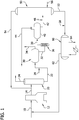
- a representative dilution steam system for ethylene production is shown in Figure 1 , in which a hydrocarbon feedstock 10 is fed into a pyrolysis furnace 12 and the effluent from the pyrolysis furnace contained in an effluent line 14 is fed to a quench water tower 20.
- the quench water tower 20 reduces the temperature of the gases in the overhead line 24 by spraying cool water from the top of the quench water tower 20. This process recovers energy, reduces undesirable side reactions, and condenses a fraction of the pyrolysis gas.
- the quench water tower bottoms are contained in a quench water tower line 22 and are sent to the quench water separator 30.
- the quench water separator 30 separates hydrocarbons from water and is the first step in cleaning the water exiting the quench water tower.
- Light hydrocarbons are contained in a light hydrocarbons line 34 and are separated from the water contained in the quench water separator line 32 that is sent to the coalescer unit comprising filters 36 and a coalescer 40.
- the coalescer unit further improves the quality of the process water by removing organic and solid materials by using the filters 36 to recover solids and the coalescer 40 to reduce hydrocarbons.
- the water contained in the quench water separator line 32 from the quench water separator 30 is first sent to the filters 36 of the coalescer unit and after filtering the water contained in the filter line 38 is sent to the coalescer 40.
- the coalescer 40 separates light oils from water.
- the light oils contained in the light oil line 44 from the coalescer are sent to the quench water separator 30 and the water from the coalescer contained in the coalescer line 42 is sent to the process water stripper 50.
- the process water stripper 50 purifies the process water by removing hydrogen sulfide, carbon dioxide, ammonia, and light hydrocarbons.
- the gases contained in the gas line 54 are typically sent to the quench water tower 20 and the bottoms contained in the process water stripper line 52 from the process water stripper 50 are sent to the dilution steam generator 60.
- Dilution steam makeup 56 can be added to the process water stripper 50 as needed.
- the dilution steam generator 60 generates dilution steam using quench oil or medium pressure steam.
- the steam drum in the dilution steam generator 60 contains a demister pad to eliminate carry over of impurities and the impurities are purged via the blow down 64.
- the treated dilution steam 62 is directed to the feed line 10 to recycle dilution steam back into the pyrolysis furnace 12.
- the neutralizing agent can be injected at one or more points within the dilution steam system for ethylene production.
- the neutralizing agent can be injected into the process water stripper line between the process water stripper and the dilution steam generator at a concentration to keep the aqueous solution in the dilution steam generator at a pH between about 9 and about 12, preferably between about 9.5 and about 10.5, thereby reducing corrosion or fouling of the dilution steam generator.
- an injection of the neutralizing agent into a dilution steam generator injection point 58 into the process water stripper line 52 can be made to maintain the pH of the aqueous solution in the dilution steam generator 60 at between about 9 and about 12, preferably between about 9.5 and about 10.5.
- the neutralizing agent can be injected into the quench water tower line between the quench water tower and the quench water separator at a concentration to keep the aqueous solution in the quench water separator at a pH between about 5.5 and 7.5, thereby reducing corrosion of the quench water separator.
- an injection of the neutralizing agent at a quench water separator point 28 into the quench water tower line 22 can be made to provide the aqueous solution in the quench water separator 30 with a pH between about 5.5 and about 7.5.
- the neutralizing agent can be injected into the quench water separator line between the coalescer and the process water stripper at a concentration to keep the aqueous solution in the process water stripper at a pH between about 8 and 9, thereby reducing corrosion or fouling of the process water stripper, and reducing ammonia contamination of the vapor exiting the process water stripper.
- an injection of the neutralizing agent at a process water stripper injection point 48 into the coalescer line 42 can be made to maintain the aqueous solution in the process water stripper 50 at a pH between about 8 and about 9.
- Another aspect of the invention is a method for inhibiting fouling and corrosion of equipment in an ethylene production plant.
- the method comprises injecting a neutralizing agent comprising a choline salt into a dilution steam system.
- the dilution steam system comprises a furnace, a quench water tower, a quench water separator, a coalescer, a process water stripper, and a dilution steam generator and the neutralizing agent is injected (i) into a process water stripper line between the process water stripper and the dilution steam generator at a concentration to keep the aqueous solution in the dilution steam generator blowdown at a pH between about 9 and about 12, thereby reducing corrosion or fouling of the dilution steam generator; (ii) into a quench water tower line between the quench water tower and the quench water separator at a concentration to keep the aqueous solution in the quench water separator at a pH between about 5.5 and 7.5, thereby reducing corrosion of the quench water
- a method of the invention inhibits fouling and corrosion of equipment in a styrene production plant and comprises injecting a neutralizing agent into a dilution steam system, the neutralizing agent having a volatility index of less than 0.005 and a pKa of 12 to 20, and being sodium-free.
- a method for inhibiting fouling and corrosion of equipment in an styrene production plant comprising injecting a neutralizing agent into a dilution steam system, the neutralizing agent comprising a choline salt stabilized by 2 wt.% to 10 wt.% alkanolamine.
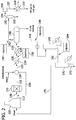
- FIG. 2 A representative dilution steam system for styrene production is shown in Figure 2 , in which an ethyl benzene feedstock in a feed line 106 is mixed with superheated steam from a superheater line 112 and fed via line 108 to a reactor 120 and reacted.
- the effluent from the reactor contained in a reactor line 122 is directed to a series of heat exchangers (e.g., heat exchanger 130, heat exchanger 134, and heat exchanger 138) to cool and condense the reactor effluent.
- the contents of heat exchanger 130 are directed to heat exchanger 134 through heat exchanger line 132, the contents of heat exchanger 134 are directed to heat exchanger 138 through the heat exchanger line 135.
- the contents of heat exchanger 138 are transferred through the heat exchanger line 139 to the separator 140, which separates vent gas from condensate and crude styrene.
- the vent gas from the separator 140 is directed through the vent gas line 142 to a gas/liquid separator 150 and the vent gas from the vent gas condenser is directed through a vent gas condenser line 154 to a vent gas compressor 156.
- the compressed vent gas is directed through a compressor line 157 to a compressor heat exchanger 158 and sent as an off gas through the off gas line 159.
- the condensate from the separator 140 is directed through the separator line 146 to the process water stripper 160.
- the process water stripper bottoms are directed through a process water stripper line 162 to a dilution steam generator 170.
- the steam from the dilution steam generator 170 can be directed through a dilution steam generator line 176 to a superheater 110.
- the steam released from the superheater 110 is directed through a superheater line 112 into the reactor 120 to react with the ethyl benzene.
- the neutralizing agent can be injected at one or more points within the dilution steam system for styrene production.
- a neutralizing agent can be injected into a heat exchanger line between two heat exchangers at a concentration to keep the condensate from the separator at a pH between about 6.5 and about 7.5, thereby reducing corrosion or fouling of the heat exchanger or separator.
- an injection of neutralizing agent can be made into the heat exchanger line 135 at heat exchanger injection point 136 to maintain the aqueous solution in the separator 140 at a pH between about 6.5 and about 7.5.
- a neutralizing agent can be injected into a vent gas line between the separator and the vent gas condenser at a concentration to keep vent gas condenser condensate at a pH between about 6.5 and 7.5, thereby reducing corrosion of the vent gas compressor.
- a neutralizing agent can be injected into the vent gas line 142 at vent gas injection point 144 to maintain the pH of the condensate in the vent gas condenser 150 at a pH between about 6.5 and 7.5.
- a neutralizing agent can be injected into a separator line between the separator and the process water stripper at a concentration to keep the aqueous solution in the process water stripper bottoms at a pH between about 8.8 and 9.2, thereby reducing corrosion or fouling of the process water stripper, and reducing ammonia contamination of the vapor exiting the process water stripper.
- a neutralizing agent can be injected into the separator line 146 at a separator line injection point 148 to maintain the pH of the aqueous solution in the process water stripper 160 is from about 8.8 to about 9.2.
- a neutralizing agent can be injected into a process water stripper line between the process water stripper and the dilution steam generator at a concentration to keep the dilution steam generator blow down at a pH between about 9.5 and 10.5, thereby reducing corrosion of the dilution steam generator.
- an injection of the neutralizing agent can be made into the process water stripper line 162 at a process water stripper injection point 164 to maintain the pH of the aqueous solution in the dilution steam generator 170 at a pH from about 9.5 to about 10.5.
- Another aspect of the invention is a method for inhibiting fouling and corrosion of equipment in a styrene production plant.
- the method comprises injecting a neutralizing agent comprising a choline salt into a dilution steam system, wherein the dilution steam system comprises a super heater, a reactor, a plurality of heat exchangers, a separator, a vent gas condenser, a vent gas compressor, a process water stripper, and a dilution steam generator and wherein the neutralizing agent is injected (i) into a heat exchanger line between two heat exchangers at a concentration to keep the condensate from the separator at a pH between about 6.5 and about 7.5, thereby reducing corrosion or fouling of the heat exchanger or separator; (ii) into a vent gas line between the separator and the vent gas condenser at a concentration to keep vent gas condenser condensate at a pH between about 6.5 and 7.5, thereby reducing corrosion of the vent
- the relationship between corrosion control and operating pH is straight foward: acidic pH conditions are corrosive, while alkaline conditions cause less corrosion.
- the relationship between pH control and fouling is not as straightforward.
- high pH in the quench water tower and oil/water separator increases the formation of stable hydrocarbon/water emulsions.
- the composition of pyrolysis gasoline can contain numerous reactive olefins and diolefins that are prone to polymerization reactions.
- the process conditions and reactants in the process water stripper can promote polymerization while solvent removal from emulsions not resolved in the oil/water separator takes place. In turn, this polymer production and solvent removal can lead to foulant (e.g., hydrocarbon polymers) deposition in the bottom of the process water stripper and in the dilution steam generator.
- ammonia is a volatile alkalizing agent, when formed, it accumulates in the quench water tower and in the oil/water separator. This ammonia accumulation causes the quench water pH to rise above the desired pH set point and the elevated pH promotes the formation of stable emulsions. When the ammonia accumulation exceeds the saturation limits of the quench water system, the ammonia can travel with the cracked gas towards the purification system. The ammonia distills with the ethylene fraction and can contaminate the final product. Thus, providing controls for the ammonia produced in the ethylene process is advantageous.
- the volatility index (or V/L ratio) of the neutralizing agent is the measure of the partition of the neutralizing agent between the vapor and liquid state at a particular pressure.
- the volatility index is determined by operating a small boiler unit. The boiler is charged with de-ionized water and a measured amount of the neutralizing agent is added to the water. The boiler is heated to a specified pressure and when steady-state at that pressure is achieved, a sample of steam is condensed and collected and simultaneously a sample of the boiler water is collected. The two water samples are then analyzed for the neutralizing agent concentration. The volatility index is then calculated by dividing the concentration of the neutralizing agent in the steam by the concentration of the neutralizing agent in the water. Then, the boiler is heated further to the next desired pressure and when steady-state is achieved, another set of samples is collected.
- the neutralizing agent can comprise a choline salt.
- the choline salt is choline hydroxide.
- the neutralizing agent is a choline salt
- the choline salt can be advantageously stabilized to provide a stabilized choline composition comprising a choline salt, a solvent, and from 2 wt.% to 10 wt.% of an alkanolamine based on the total weight of the composition.
- the stabilized choline composition can have a concentration of choline salt from 10 wt.% to 50 wt.%, from 15 wt.% to 30 wt.%, from 15 wt.% to 25 wt.%, or 20 wt.% based on the total weight of the composition.
- the stabilized choline composition can comprise an alkanolamine such as methanolamine, ethanolamine (i.e., monoethanolamine (MEA)), propanolamine, butanolamine, or a combination thereof.
- an alkanolamine such as methanolamine, ethanolamine (i.e., monoethanolamine (MEA)), propanolamine, butanolamine, or a combination thereof.
- the alkanolamine is methanolamine, ethanolamine, or a combination thereof. More preferably, the alkanolamine comprises ethanolamine (MEA).
- the stabilized choline composition can comprise the alkanolamine in a concentration from 3 wt.% to 8 wt.%, 4 wt.% to 6 wt.%, or 5 wt.% based on the total weight of the composition.
- the solvent in the stabilized choline composition can comprise water.
- an ethylene plant is a dynamic process with minor shifts in feedstock composition, process flow rates, temperature fluctuations, and other process conditions and as a result, the concentration of acids to be neutralized is can vary slightly.
- the preferred, stabilized neutralizing agent of this invention is additionally advantageous because the relationship between the pH of the solution and the concentration of neutralizing agent used (i.e., the neutralization profile) goes from a nearly vertical rise in pH at pHs of 9 and below to a less steep pH rise when concentration of the neutralizing agent keeps the solution between pH 9 to 12, preferably, between pH 9.5 to 10.5.
- This pH target of 9 to 12, preferably, pH 9.5 to 10.5 is sought in the dilution steam generator, where corrosion is the greatest concern.
- This neutralizing profile for the neutralizing agent described herein means that less of the neutralizing agent is needed to maintain the solution it is used to neutralize (e.g., dilution steam) at the desired pH.
- the neutralizing agent can be injected into the system in a variety of ways known to a person of skill in the art.
- the injection control may be a microprocessor, a central process unit, or any other similar device capable of processing the signal output from the acid measurement device and controlling the rate of dispensation of the neutralizing agent in response to this signal.
- the injection control may be integral with the neutralizing agent injector or it may be separate. Suitable injection controllers would include control systems that are well known in the art.
- the acid concentration detector may be any one of a number of devices capable of generating a signal responsive to the concentration of acid in the dilution steam system. Automated titrators are particularly effective acid measuring devices. A number of automated titrators suitable for use in the system are commercially available including those from Rosemount Inc., Honeywell, Hach, or Mettler Toledo.
- Example 1 Titration of 1300 ppm of Acetic Acid with Neat Ethanolamine (MEA)
- the solution was initially diluted according to the following procedure. Into a glass container was added 10.0 g of neat MEA. This was diluted to a total mass of 500 g using deionized water.
- a solution of 1300 ppm acetic acid was prepared by adding 0.652 g of 99.7 % (purity) glacial acetic acid to a 500 mL volumetric flask. To this flask was added deionized water to give 500 mL of final solution. A 30 mL aliquot of this solution was added to a 100 mL titration vial. Using a pH meter, the initial pH of this solution was measured. Thereafter, the diluted solution of neat MEA was added to the vial in small quantities at a time while the pH of the solution was measured at every point. The titration was continued until the solution had the target pH of 10.5. To reach this pH, 8154 ppm of the neutralizer was required.
- MEA is volatile such that a third of the neutralizer evaporates before neutralizing the acids in the water.
- a formulation containing 66.4 % (w/w) of MEA and 33.6 % (w/w) deionized water was prepared. This formulation was used to neutralize 30 mL of 1300 ppm acetic acid following the procedure in Example 1. To reach the target pH of 10.5, a total amount of 9792 ppm of the neutralizer formulation was added to the acetic acid solution.
- Heavy neutralizer formulations were prepared by blending MEA with 45 % (w/w) choline hydroxide.
- the heavy neutralizer formulation was prepared by adding 3 g of ethanolamine (MEA) to a glass bottle containing 97 g of an aqueous solution of 45 % (w/w) choline hydroxide. This contained 3 % (w/w) of MEA and 43.4 % % (w/w) of choline hydroxide solution.
- 10 g of this neutralizer was initially diluted with deionized water yield a total mass of 500 g.
- Example 2 The same stock solution of 1300 ppm acetic acid prepared in Example 1 was used for the titration with the diluted solution of the heavy neutralizer comprising 3 % (w/w) MEA and 43.4 % (w/w) of choline hydroxide. Similar to Example 2, the diluted solution of the heavy neutralizer formulation was added in small quantities while monitoring the pH of the solution after each addition of the neutralizer until the pH of the solution was basic and the pH plateaued off. A total concentration of 4846 ppm of this heavy neutralizer was consumed to attain the pH of 10.5.
- the untreated 45 wt.% choline hydroxide sample had a brown supernatant and brown sediment at the bottom of the container.
- the untreated 20 wt.% choline hydroxide sample also had a brown supernatant but less brown sediment was observed.
- the treated 20 wt.% choline hydroxide sample did not have any sediment, and was pale amber in color.
- a stock solution of aqueous choline hydroxide (20.83 wt.%) was prepared by dilution of 40.195 g aqueous choline hydroxide solution (45 wt.%) with 48.552 g deionized water.
- To a sample of 24.0 g of the stock solution was added 1.0 g ethanolamine.
Landscapes
- Chemical & Material Sciences (AREA)
- Engineering & Computer Science (AREA)
- Materials Engineering (AREA)
- Organic Chemistry (AREA)
- Mechanical Engineering (AREA)
- Metallurgy (AREA)
- Inorganic Chemistry (AREA)
- Preventing Corrosion Or Incrustation Of Metals (AREA)
- Organic Low-Molecular-Weight Compounds And Preparation Thereof (AREA)
Claims (12)
- Verfahren zum Hemmen von Verschmutzung und Korrosion von Ausrüstungen in einer Ethylen- oder Styrolproduktionsanlage, wobei das Verfahren ein Einspritzen eines Neutralisationsmittels in ein Verdünnungsdampfsystem umfasst, wobei das Neutralisationsmittel einen Flüchtigkeitsindex von weniger als 0,005 und einen pKa-Wert von 12 bis 20 aufweist und natriumfrei ist, wobei das Neutralisationsmittel ein Cholinsalz ist, wobei das Cholinsalz in einer stabilisierten Cholinzusammensetzung stabilisiert ist, die ein Cholinsalz, ein Lösungsmittel und 2 Gew.-% bis 10 Gew.-% eines Alkanolamins, basierend auf dem Gesamtgewicht der Zusammensetzung, umfasst.
- Verfahren nach Anspruch 1, wobei das Alkanolamin Ethanolamin umfasst.
- Verfahren nach Anspruch 1 oder 2, wobei das Cholinsalz Cholinhydroxid ist.
- Verfahren nach einem der Ansprüche 1 bis 3, wobei das Verdünnungsdampfsystem der Ethylenproduktionsanlage einen Ofen, einen Löschwasserturm, einen Löschwasserabscheider, einen Koaleszer, einen Prozesswasserstripper und einen Verdünnungsdampferzeuger umfasst und wobei das Neutralisationsmittel in eine der Folgenden eingespritzt wird:(i) in eine Prozesswasserstripperleitung zwischen dem Prozesswasserstripper und dem Verdünnungsdampferzeuger in einer Konzentration, um die wässrige Lösung in einer Ausblasung des Verdünnungsdampferzeugers auf einem pH-Wert zwischen 9 und 12 zu halten, wobei dadurch die Korrosion oder die Verschmutzung des Verdünnungsdampferzeugers verringert wird;(ii) in eine Löschwasserturmleitung zwischen dem Löschwasserturm und dem Löschwasserabscheider in einer Konzentration, um die wässrige Lösung in dem Löschwasserabscheider auf einem pH-Wert zwischen 5,5 und 7,5 zu halten, wobei dadurch die Korrosion des Löschwasserabscheiders verringert wird; oder(iii) in eine Koaleszerleitung zwischen dem Koaleszer und dem Prozesswasserstripper in einer Konzentration, um die wässrige Lösung in einer Bodenentleerung des Prozesswasserstrippers auf einem pH-Wert zwischen 8 und 9 zu halten, wobei dadurch die Korrosion oder die Verschmutzung des Prozesswasserstrippers und die Ammoniakverunreinigung des Dunstes, der aus dem Prozesswasserstripper austritt, verringert wird.
- Verfahren nach Anspruch 4, wobei das Neutralisationsmittel in die Prozesswasserstripperleitung zwischen dem Prozesswasserstripper und dem Verdünnungsdampferzeuger in einer Konzentration eingespritzt wird, um die wässrige Lösung in dem Verdünnungsdampferzeuger auf einem pH-Wert zwischen 9,5 und 10,5 zu halten, wobei dadurch die Korrosion oder die Verschmutzung des Verdünnungsdampferzeugers verringert wird.
- Verfahren nach Anspruch 4 oder 5, wobei das Neutralisationsmittel in die Löschwasserturmleitung zwischen dem Löschwasserturm und dem Löschwasserabscheider in einer Konzentration eingespritzt wird, um die wässrige Lösung in dem Löschwasserabscheider auf einem pH-Wert zwischen 5,5 und 7,5 zu halten, wobei dadurch die Korrosion des Löschwasserabscheiders verringert wird.
- Verfahren nach einem der Ansprüche 4 bis 6, wobei das Neutralisationsmittel in die Koaleszerleitung zwischen dem Koaleszer und dem Prozesswasserstripper in einer Konzentration eingespritzt wird, um die wässrige Lösung in dem Prozesswasserstripper auf einem pH-Wert zwischen 8 und 9 zu halten, wobei dadurch die Korrosion oder die Verschmutzung des Prozesswasserstrippers und die Ammoniakverunreinigung des Dunstes, der aus dem Prozesswasserstripper austritt, verringert wird.
- Verfahren nach einem der Ansprüche 1 bis 3, wobei das Verdünnungsdampfsystem der Styrolproduktionsanlage einen Überhitzer, einen Reaktor, mehrere Wärmetauscher, einen Abscheider, einen Abgaskondensator, einen Abgasverdichter, einen Prozesswasserstripper und einen Verdünnungsdampferzeuger umfasst, und wobei das Neutralisationsmittel in eine der Folgenden eingespritzt wird:(i) in eine Wärmetauscherleitung zwischen zwei Wärmetauschern in einer Konzentration, um das Kondensat aus dem Abscheider auf einem pH-Wert zwischen 6,5 und 7,5 zu halten, wobei dadurch die Korrosion oder die Verschmutzung des Wärmetauschers oder des Abscheiders verringert wird;(ii) in eine Abgasleitung zwischen dem Abscheider und dem Abgaskondensator in einer Konzentration, um ein Kondensat des Abgaskondensators auf einem pH-Wert zwischen 6,5 und 7,5 zu halten, wobei dadurch die Korrosion des Abgasverdichters verringert wird;(iii) in eine Abscheiderleitung zwischen dem Abscheider und dem Prozesswasserstripper in einer Konzentration, um die wässrige Lösung auf den Böden des Prozesswasserstrippers auf einem pH-Wert zwischen 8,8 und 9,2 zu halten, wobei dadurch die Korrosion oder die Verschmutzung des Prozesswasserstrippers und die Ammoniakverunreinigung des Dunstes, der aus dem Prozesswasserstripper austritt, verringert wird; oder(iv) in eine Prozesswasserstripperleitung zwischen dem Prozesswasserstripper und dem Verdünnungsdampferzeuger in einer Konzentration, um das Ausblasen des Verdünnungsdampferzeugers auf einem pH-Wert zwischen 9 und 12 zu halten, wobei dadurch die Korrosion des Verdünnungsdampferzeugers verringert wird.
- Verfahren nach Anspruch 8, wobei das Neutralisationsmittel in die Wärmetauscherleitung zwischen zwei Wärmetauschern in einer Konzentration eingespritzt wird, um das Kondensat aus dem Abscheider auf einem pH-Wert zwischen 6,5 und 7,5 zu halten, wobei dadurch die Korrosion oder die Verschmutzung des Wärmetauschers verringert wird.
- Verfahren nach Anspruch 8 oder 9, wobei das Neutralisationsmittel in die Abgasleitung zwischen dem Abscheider und dem Abgaskondensator in einer Konzentration eingespritzt wird, um das Kondensat des Abgaskondensators auf einem pH-Wert zwischen 6,5 und 7,5 zu halten, wobei dadurch die Korrosion des Abgasverdichters verringert wird.
- Verfahren nach einem der Ansprüche 8 bis 10, wobei das Neutralisationsmittel in die Abscheiderleitung zwischen dem Abscheider und dem Prozesswasserstripper in einer Konzentration eingespritzt wird, um die wässrige Lösung auf den Böden des Prozesswasserstrippers auf einem pH-Wert zwischen 8,8 und 9,2 zu halten, wobei dadurch die Korrosion oder die Verschmutzung des Prozesswasserstrippers und die Ammoniakverunreinigung des Dunstes, der aus dem Prozesswasserstripper austritt, verringert wird.
- Verfahren nach einem der Ansprüche 8 bis 11, wobei das Neutralisationsmittel in die Prozesswasserstripperleitung zwischen dem Prozesswasserstripper und dem Verdünnungsdampferzeuger in einer Konzentration eingespritzt wird, um das Ausblasen des Verdünnungsdampferzeugers auf einem pH-Wert zwischen 9,5 und 10,5 zu halten, wobei dadurch die Korrosion des Verdünnungsdampferzeugers verringert wird.
Applications Claiming Priority (2)
| Application Number | Priority Date | Filing Date | Title |
|---|---|---|---|
| US14/186,160 US9297081B2 (en) | 2014-02-21 | 2014-02-21 | Use of neutralizing agent in olefin or styrene production |
| PCT/US2015/015170 WO2015126669A1 (en) | 2014-02-21 | 2015-02-10 | Use of neutralizing agent in olefin or styrene production |
Publications (3)
| Publication Number | Publication Date |
|---|---|
| EP3107882A1 EP3107882A1 (de) | 2016-12-28 |
| EP3107882A4 EP3107882A4 (de) | 2017-11-01 |
| EP3107882B1 true EP3107882B1 (de) | 2020-12-02 |
Family
ID=53878825
Family Applications (1)
| Application Number | Title | Priority Date | Filing Date |
|---|---|---|---|
| EP15752158.4A Active EP3107882B1 (de) | 2014-02-21 | 2015-02-10 | Verwendung eines neutralisierungsmittels bei der herstellung von olefin oder styrol |
Country Status (12)
| Country | Link |
|---|---|
| US (1) | US9297081B2 (de) |
| EP (1) | EP3107882B1 (de) |
| JP (1) | JP6608837B2 (de) |
| KR (1) | KR102437011B1 (de) |
| CN (1) | CN106103391B (de) |
| BR (1) | BR112016019271B1 (de) |
| CA (1) | CA2940231C (de) |
| MY (1) | MY176057A (de) |
| SA (1) | SA516371693B1 (de) |
| SG (1) | SG11201606922YA (de) |
| TW (1) | TWI653319B (de) |
| WO (1) | WO2015126669A1 (de) |
Families Citing this family (7)
| Publication number | Priority date | Publication date | Assignee | Title |
|---|---|---|---|---|
| US20150376040A1 (en) * | 2014-06-26 | 2015-12-31 | Baker Hughes Incorporated | ADDITIVES FOR OLEFIN PLANT QUENCHING FLUID pH CONTROL |
| CA2993822C (en) | 2015-07-29 | 2022-07-12 | Ecolab Usa Inc. | Heavy amine neutralizing agents for olefin or styrene production |
| US10767116B2 (en) * | 2015-09-29 | 2020-09-08 | Dow Global Technologies Llc | Method and composition for neutralizing acidic components in petroleum refining units |
| US9969944B2 (en) * | 2016-09-23 | 2018-05-15 | Janus Technology Solutions, LLC | Dissolved oil removal from quench water of gas cracker ethylene plants |
| CN109486562A (zh) * | 2017-09-13 | 2019-03-19 | 艺康美国股份有限公司 | 用于甲醇制烯烃工艺的水系统的洗涤剂 |
| CN110713864B (zh) | 2018-07-13 | 2023-09-26 | Bl 科技公司 | 防污分散剂组合物和使用方法 |
| KR102688678B1 (ko) * | 2021-12-13 | 2024-07-26 | 주식회사 켐스 엔바이오 | 폐수 저감형 에틸렌 생산 공정용 희석 스팀 시스템 |
Family Cites Families (21)
| Publication number | Priority date | Publication date | Assignee | Title |
|---|---|---|---|---|
| JPS5448543A (en) * | 1978-04-21 | 1979-04-17 | Bunshodo Co Ltd | Diazo photographic developer |
| US4600518A (en) | 1985-07-15 | 1986-07-15 | Nalco Chemical Company | Choline for neutralizing naphthenic acid in fuel and lubricating oils |
| US4594147A (en) | 1985-12-16 | 1986-06-10 | Nalco Chemical Company | Choline as a fuel sweetener and sulfur antagonist |
| JPH0637622B2 (ja) * | 1986-07-04 | 1994-05-18 | 栗田工業株式会社 | 石油精製又は石油プロセス用中和剤 |
| US4686002A (en) | 1986-07-18 | 1987-08-11 | Syntex (U.S.A.) Inc. | Stabilized choline base solutions |
| US5209858A (en) | 1991-02-06 | 1993-05-11 | E. I. Du Pont De Nemours And Company | Stabilization of choline and its derivatives against discoloration |
| US5173213A (en) * | 1991-11-08 | 1992-12-22 | Baker Hughes Incorporated | Corrosion and anti-foulant composition and method of use |
| US5302253A (en) | 1992-04-13 | 1994-04-12 | Nalco Chemical Company | On-line acid monitor and neutralizer feed control of the overhead water in oil refineries |
| DE60110072T2 (de) | 2001-09-27 | 2006-01-26 | Kurita Europe Gmbh | Verfahren zur Verhütung von Verschmutzung und Korrosion durch Ammoniumchlorid und Ammoniumsulfat |
| CN100523301C (zh) * | 2002-11-12 | 2009-08-05 | 栗田工业株式会社 | 在原油常压蒸馏装置内的金属腐蚀抑制剂和氯化氢形成抑制剂 |
| JP3692449B2 (ja) * | 2002-11-12 | 2005-09-07 | 栗田工業株式会社 | 原油常圧蒸留装置における塩化水素発生防止剤および塩化水素発生防止方法 |
| JP3962919B2 (ja) * | 2002-11-12 | 2007-08-22 | 栗田工業株式会社 | 金属防食剤、金属防食方法、原油常圧蒸留装置における塩化水素発生防止剤および塩化水素発生防止方法 |
| US7125483B2 (en) | 2003-04-10 | 2006-10-24 | Equistar Chemicals, Lp | Corrosion control in olefin production plants |
| JP2007078291A (ja) * | 2005-09-15 | 2007-03-29 | Idemitsu Kosan Co Ltd | スチレンモノマー製造装置ボイラー給水の処理方法及び処理装置並びにその利用 |
| US8277639B2 (en) | 2005-09-20 | 2012-10-02 | Exxonmobil Chemical Patents Inc. | Steam cracking of high TAN crudes |
| US7582201B2 (en) | 2006-12-05 | 2009-09-01 | Exxonmobil Chemical Patents Inc. | Controlling tar by quenching cracked effluent from a liquid fed gas cracker |
| CN102811955B (zh) * | 2010-01-26 | 2014-07-30 | 控制工程学公司 | 除去沉积物的方法与组合物 |
| US20140361217A1 (en) | 2011-11-22 | 2014-12-11 | Taminco | Stabilized choline solutions and methods for preparing the same |
| EP2836479A4 (de) * | 2012-04-13 | 2015-10-28 | Huntsman Petrochemical Llc | Verwendung neuartiger amine zur stabilisierung von quaternären trialkylalkanolaminen |
| KR101880308B1 (ko) | 2012-05-24 | 2018-07-19 | 동우 화인켐 주식회사 | Tft 제조용 레지스트 박리제 조성물 및 이를 이용한 tft의 제조방법 |
| KR102338550B1 (ko) * | 2013-06-06 | 2021-12-14 | 엔테그리스, 아이엔씨. | 질화 티타늄의 선택적인 에칭을 위한 조성물 및 방법 |
-
2014
- 2014-02-21 US US14/186,160 patent/US9297081B2/en active Active
-
2015
- 2015-02-10 EP EP15752158.4A patent/EP3107882B1/de active Active
- 2015-02-10 MY MYPI2016001535A patent/MY176057A/en unknown
- 2015-02-10 SG SG11201606922YA patent/SG11201606922YA/en unknown
- 2015-02-10 KR KR1020167025915A patent/KR102437011B1/ko active Active
- 2015-02-10 CA CA2940231A patent/CA2940231C/en active Active
- 2015-02-10 BR BR112016019271-0A patent/BR112016019271B1/pt active IP Right Grant
- 2015-02-10 WO PCT/US2015/015170 patent/WO2015126669A1/en not_active Ceased
- 2015-02-10 JP JP2016553513A patent/JP6608837B2/ja active Active
- 2015-02-10 TW TW104104311A patent/TWI653319B/zh active
- 2015-02-10 CN CN201580014790.1A patent/CN106103391B/zh active Active
-
2016
- 2016-08-18 SA SA516371693A patent/SA516371693B1/ar unknown
Non-Patent Citations (1)
| Title |
|---|
| None * |
Also Published As
| Publication number | Publication date |
|---|---|
| EP3107882A1 (de) | 2016-12-28 |
| MY176057A (en) | 2020-07-23 |
| CN106103391A (zh) | 2016-11-09 |
| KR102437011B1 (ko) | 2022-08-25 |
| TWI653319B (zh) | 2019-03-11 |
| JP2017514986A (ja) | 2017-06-08 |
| JP6608837B2 (ja) | 2019-11-20 |
| EP3107882A4 (de) | 2017-11-01 |
| WO2015126669A1 (en) | 2015-08-27 |
| CA2940231C (en) | 2022-05-17 |
| US9297081B2 (en) | 2016-03-29 |
| SG11201606922YA (en) | 2016-09-29 |
| KR20160124859A (ko) | 2016-10-28 |
| SA516371693B1 (ar) | 2019-05-16 |
| TW201546243A (zh) | 2015-12-16 |
| CN106103391B (zh) | 2020-03-06 |
| BR112016019271B1 (pt) | 2021-03-30 |
| CA2940231A1 (en) | 2015-08-27 |
| US20150240366A1 (en) | 2015-08-27 |
Similar Documents
| Publication | Publication Date | Title |
|---|---|---|
| CA2940231C (en) | Use of neutralizing agent in olefin or styrene production | |
| CN1066208C (zh) | 使用胺掺混物抑制湿烃冷凝系统中氯化物腐蚀的方法 | |
| JPS63502192A (ja) | オレフィン系化合物を含有する炭化水素組成物の着き垢抑制方法 | |
| EP2820110B1 (de) | Dampferzeugeradditive zur minimierung von verschmutzung und korrosion in rohöltürmen | |
| EP3328969B1 (de) | Neutralisierungsmittel mit schweren aminen zur herstellung von olefin oder styrol | |
| CN114752412A (zh) | 在工艺水中抑制聚合的方法 | |
| US12606916B2 (en) | Method for reducing or preventing corrosion or fouling caused by acidic compounds | |
| KR20120028874A (ko) | 탄화수소 처리시 오염을 억제하는 방법 | |
| US20020139710A1 (en) | Control carbonyl concentration in diolefinic products using hydroxyamine sulfate as an extraction aid | |
| WO2004007642A1 (en) | Method for reducing foam in a primary fractionator | |
| JP2002047214A (ja) | エチレン製造装置の汚れ防止方法 | |
| WO2014127436A1 (pt) | Processo de produção de olefínas a partir de etanol combustível | |
| Kolmetz et al. | Design guidelines for chemical treatments in distillation columns | |
| US10767116B2 (en) | Method and composition for neutralizing acidic components in petroleum refining units |
Legal Events
| Date | Code | Title | Description |
|---|---|---|---|
| PUAI | Public reference made under article 153(3) epc to a published international application that has entered the european phase |
Free format text: ORIGINAL CODE: 0009012 |
|
| STAA | Information on the status of an ep patent application or granted ep patent |
Free format text: STATUS: REQUEST FOR EXAMINATION WAS MADE |
|
| 17P | Request for examination filed |
Effective date: 20160913 |
|
| AK | Designated contracting states |
Kind code of ref document: A1 Designated state(s): AL AT BE BG CH CY CZ DE DK EE ES FI FR GB GR HR HU IE IS IT LI LT LU LV MC MK MT NL NO PL PT RO RS SE SI SK SM TR |
|
| AX | Request for extension of the european patent |
Extension state: BA ME |
|
| DAX | Request for extension of the european patent (deleted) | ||
| RAP1 | Party data changed (applicant data changed or rights of an application transferred) |
Owner name: ECOLAB USA INC. |
|
| REG | Reference to a national code |
Ref country code: DE Ref legal event code: R079 Ref document number: 602015062893 Country of ref document: DE Free format text: PREVIOUS MAIN CLASS: C07C0007040000 Ipc: C23F0015000000 |
|
| A4 | Supplementary search report drawn up and despatched |
Effective date: 20171004 |
|
| RIC1 | Information provided on ipc code assigned before grant |
Ipc: C23F 15/00 20060101AFI20170927BHEP Ipc: C09K 15/20 20060101ALI20170927BHEP |
|
| STAA | Information on the status of an ep patent application or granted ep patent |
Free format text: STATUS: EXAMINATION IS IN PROGRESS |
|
| 17Q | First examination report despatched |
Effective date: 20190418 |
|
| GRAP | Despatch of communication of intention to grant a patent |
Free format text: ORIGINAL CODE: EPIDOSNIGR1 |
|
| STAA | Information on the status of an ep patent application or granted ep patent |
Free format text: STATUS: GRANT OF PATENT IS INTENDED |
|
| INTG | Intention to grant announced |
Effective date: 20200407 |
|
| GRAJ | Information related to disapproval of communication of intention to grant by the applicant or resumption of examination proceedings by the epo deleted |
Free format text: ORIGINAL CODE: EPIDOSDIGR1 |
|
| STAA | Information on the status of an ep patent application or granted ep patent |
Free format text: STATUS: EXAMINATION IS IN PROGRESS |
|
| GRAP | Despatch of communication of intention to grant a patent |
Free format text: ORIGINAL CODE: EPIDOSNIGR1 |
|
| STAA | Information on the status of an ep patent application or granted ep patent |
Free format text: STATUS: GRANT OF PATENT IS INTENDED |
|
| INTC | Intention to grant announced (deleted) | ||
| INTG | Intention to grant announced |
Effective date: 20200622 |
|
| GRAS | Grant fee paid |
Free format text: ORIGINAL CODE: EPIDOSNIGR3 |
|
| GRAA | (expected) grant |
Free format text: ORIGINAL CODE: 0009210 |
|
| STAA | Information on the status of an ep patent application or granted ep patent |
Free format text: STATUS: THE PATENT HAS BEEN GRANTED |
|
| AK | Designated contracting states |
Kind code of ref document: B1 Designated state(s): AL AT BE BG CH CY CZ DE DK EE ES FI FR GB GR HR HU IE IS IT LI LT LU LV MC MK MT NL NO PL PT RO RS SE SI SK SM TR |
|
| REG | Reference to a national code |
Ref country code: GB Ref legal event code: FG4D |
|
| REG | Reference to a national code |
Ref country code: AT Ref legal event code: REF Ref document number: 1341038 Country of ref document: AT Kind code of ref document: T Effective date: 20201215 Ref country code: CH Ref legal event code: EP |
|
| REG | Reference to a national code |
Ref country code: IE Ref legal event code: FG4D |
|
| REG | Reference to a national code |
Ref country code: DE Ref legal event code: R096 Ref document number: 602015062893 Country of ref document: DE |
|
| REG | Reference to a national code |
Ref country code: NL Ref legal event code: FP |
|
| PG25 | Lapsed in a contracting state [announced via postgrant information from national office to epo] |
Ref country code: FI Free format text: LAPSE BECAUSE OF FAILURE TO SUBMIT A TRANSLATION OF THE DESCRIPTION OR TO PAY THE FEE WITHIN THE PRESCRIBED TIME-LIMIT Effective date: 20201202 Ref country code: RS Free format text: LAPSE BECAUSE OF FAILURE TO SUBMIT A TRANSLATION OF THE DESCRIPTION OR TO PAY THE FEE WITHIN THE PRESCRIBED TIME-LIMIT Effective date: 20201202 Ref country code: NO Free format text: LAPSE BECAUSE OF FAILURE TO SUBMIT A TRANSLATION OF THE DESCRIPTION OR TO PAY THE FEE WITHIN THE PRESCRIBED TIME-LIMIT Effective date: 20210302 Ref country code: GR Free format text: LAPSE BECAUSE OF FAILURE TO SUBMIT A TRANSLATION OF THE DESCRIPTION OR TO PAY THE FEE WITHIN THE PRESCRIBED TIME-LIMIT Effective date: 20210303 |
|
| REG | Reference to a national code |
Ref country code: AT Ref legal event code: MK05 Ref document number: 1341038 Country of ref document: AT Kind code of ref document: T Effective date: 20201202 |
|
| PG25 | Lapsed in a contracting state [announced via postgrant information from national office to epo] |
Ref country code: PL Free format text: LAPSE BECAUSE OF FAILURE TO SUBMIT A TRANSLATION OF THE DESCRIPTION OR TO PAY THE FEE WITHIN THE PRESCRIBED TIME-LIMIT Effective date: 20201202 Ref country code: LV Free format text: LAPSE BECAUSE OF FAILURE TO SUBMIT A TRANSLATION OF THE DESCRIPTION OR TO PAY THE FEE WITHIN THE PRESCRIBED TIME-LIMIT Effective date: 20201202 Ref country code: SE Free format text: LAPSE BECAUSE OF FAILURE TO SUBMIT A TRANSLATION OF THE DESCRIPTION OR TO PAY THE FEE WITHIN THE PRESCRIBED TIME-LIMIT Effective date: 20201202 Ref country code: BG Free format text: LAPSE BECAUSE OF FAILURE TO SUBMIT A TRANSLATION OF THE DESCRIPTION OR TO PAY THE FEE WITHIN THE PRESCRIBED TIME-LIMIT Effective date: 20210302 |
|
| PG25 | Lapsed in a contracting state [announced via postgrant information from national office to epo] |
Ref country code: HR Free format text: LAPSE BECAUSE OF FAILURE TO SUBMIT A TRANSLATION OF THE DESCRIPTION OR TO PAY THE FEE WITHIN THE PRESCRIBED TIME-LIMIT Effective date: 20201202 |
|
| REG | Reference to a national code |
Ref country code: LT Ref legal event code: MG9D |
|
| PG25 | Lapsed in a contracting state [announced via postgrant information from national office to epo] |
Ref country code: LT Free format text: LAPSE BECAUSE OF FAILURE TO SUBMIT A TRANSLATION OF THE DESCRIPTION OR TO PAY THE FEE WITHIN THE PRESCRIBED TIME-LIMIT Effective date: 20201202 Ref country code: SK Free format text: LAPSE BECAUSE OF FAILURE TO SUBMIT A TRANSLATION OF THE DESCRIPTION OR TO PAY THE FEE WITHIN THE PRESCRIBED TIME-LIMIT Effective date: 20201202 Ref country code: RO Free format text: LAPSE BECAUSE OF FAILURE TO SUBMIT A TRANSLATION OF THE DESCRIPTION OR TO PAY THE FEE WITHIN THE PRESCRIBED TIME-LIMIT Effective date: 20201202 Ref country code: PT Free format text: LAPSE BECAUSE OF FAILURE TO SUBMIT A TRANSLATION OF THE DESCRIPTION OR TO PAY THE FEE WITHIN THE PRESCRIBED TIME-LIMIT Effective date: 20210405 Ref country code: SM Free format text: LAPSE BECAUSE OF FAILURE TO SUBMIT A TRANSLATION OF THE DESCRIPTION OR TO PAY THE FEE WITHIN THE PRESCRIBED TIME-LIMIT Effective date: 20201202 Ref country code: CZ Free format text: LAPSE BECAUSE OF FAILURE TO SUBMIT A TRANSLATION OF THE DESCRIPTION OR TO PAY THE FEE WITHIN THE PRESCRIBED TIME-LIMIT Effective date: 20201202 Ref country code: EE Free format text: LAPSE BECAUSE OF FAILURE TO SUBMIT A TRANSLATION OF THE DESCRIPTION OR TO PAY THE FEE WITHIN THE PRESCRIBED TIME-LIMIT Effective date: 20201202 |
|
| PG25 | Lapsed in a contracting state [announced via postgrant information from national office to epo] |
Ref country code: AT Free format text: LAPSE BECAUSE OF FAILURE TO SUBMIT A TRANSLATION OF THE DESCRIPTION OR TO PAY THE FEE WITHIN THE PRESCRIBED TIME-LIMIT Effective date: 20201202 |
|
| REG | Reference to a national code |
Ref country code: DE Ref legal event code: R119 Ref document number: 602015062893 Country of ref document: DE |
|
| PG25 | Lapsed in a contracting state [announced via postgrant information from national office to epo] |
Ref country code: IS Free format text: LAPSE BECAUSE OF FAILURE TO SUBMIT A TRANSLATION OF THE DESCRIPTION OR TO PAY THE FEE WITHIN THE PRESCRIBED TIME-LIMIT Effective date: 20210402 Ref country code: MC Free format text: LAPSE BECAUSE OF FAILURE TO SUBMIT A TRANSLATION OF THE DESCRIPTION OR TO PAY THE FEE WITHIN THE PRESCRIBED TIME-LIMIT Effective date: 20201202 |
|
| PLBE | No opposition filed within time limit |
Free format text: ORIGINAL CODE: 0009261 |
|
| STAA | Information on the status of an ep patent application or granted ep patent |
Free format text: STATUS: NO OPPOSITION FILED WITHIN TIME LIMIT |
|
| REG | Reference to a national code |
Ref country code: BE Ref legal event code: MM Effective date: 20210228 |
|
| PG25 | Lapsed in a contracting state [announced via postgrant information from national office to epo] |
Ref country code: CH Free format text: LAPSE BECAUSE OF NON-PAYMENT OF DUE FEES Effective date: 20210228 Ref country code: AL Free format text: LAPSE BECAUSE OF FAILURE TO SUBMIT A TRANSLATION OF THE DESCRIPTION OR TO PAY THE FEE WITHIN THE PRESCRIBED TIME-LIMIT Effective date: 20201202 Ref country code: LI Free format text: LAPSE BECAUSE OF NON-PAYMENT OF DUE FEES Effective date: 20210228 Ref country code: LU Free format text: LAPSE BECAUSE OF NON-PAYMENT OF DUE FEES Effective date: 20210210 |
|
| 26N | No opposition filed |
Effective date: 20210903 |
|
| GBPC | Gb: european patent ceased through non-payment of renewal fee |
Effective date: 20210302 |
|
| PG25 | Lapsed in a contracting state [announced via postgrant information from national office to epo] |
Ref country code: SI Free format text: LAPSE BECAUSE OF FAILURE TO SUBMIT A TRANSLATION OF THE DESCRIPTION OR TO PAY THE FEE WITHIN THE PRESCRIBED TIME-LIMIT Effective date: 20201202 Ref country code: DK Free format text: LAPSE BECAUSE OF FAILURE TO SUBMIT A TRANSLATION OF THE DESCRIPTION OR TO PAY THE FEE WITHIN THE PRESCRIBED TIME-LIMIT Effective date: 20201202 Ref country code: ES Free format text: LAPSE BECAUSE OF FAILURE TO SUBMIT A TRANSLATION OF THE DESCRIPTION OR TO PAY THE FEE WITHIN THE PRESCRIBED TIME-LIMIT Effective date: 20201202 |
|
| PG25 | Lapsed in a contracting state [announced via postgrant information from national office to epo] |
Ref country code: IE Free format text: LAPSE BECAUSE OF NON-PAYMENT OF DUE FEES Effective date: 20210210 Ref country code: GB Free format text: LAPSE BECAUSE OF NON-PAYMENT OF DUE FEES Effective date: 20210302 Ref country code: DE Free format text: LAPSE BECAUSE OF NON-PAYMENT OF DUE FEES Effective date: 20210901 |
|
| PG25 | Lapsed in a contracting state [announced via postgrant information from national office to epo] |
Ref country code: IS Free format text: LAPSE BECAUSE OF FAILURE TO SUBMIT A TRANSLATION OF THE DESCRIPTION OR TO PAY THE FEE WITHIN THE PRESCRIBED TIME-LIMIT Effective date: 20210402 |
|
| PG25 | Lapsed in a contracting state [announced via postgrant information from national office to epo] |
Ref country code: BE Free format text: LAPSE BECAUSE OF NON-PAYMENT OF DUE FEES Effective date: 20210228 |
|
| PG25 | Lapsed in a contracting state [announced via postgrant information from national office to epo] |
Ref country code: HU Free format text: LAPSE BECAUSE OF FAILURE TO SUBMIT A TRANSLATION OF THE DESCRIPTION OR TO PAY THE FEE WITHIN THE PRESCRIBED TIME-LIMIT; INVALID AB INITIO Effective date: 20150210 |
|
| PG25 | Lapsed in a contracting state [announced via postgrant information from national office to epo] |
Ref country code: CY Free format text: LAPSE BECAUSE OF FAILURE TO SUBMIT A TRANSLATION OF THE DESCRIPTION OR TO PAY THE FEE WITHIN THE PRESCRIBED TIME-LIMIT Effective date: 20201202 |
|
| PG25 | Lapsed in a contracting state [announced via postgrant information from national office to epo] |
Ref country code: MK Free format text: LAPSE BECAUSE OF FAILURE TO SUBMIT A TRANSLATION OF THE DESCRIPTION OR TO PAY THE FEE WITHIN THE PRESCRIBED TIME-LIMIT Effective date: 20201202 |
|
| PG25 | Lapsed in a contracting state [announced via postgrant information from national office to epo] |
Ref country code: TR Free format text: LAPSE BECAUSE OF FAILURE TO SUBMIT A TRANSLATION OF THE DESCRIPTION OR TO PAY THE FEE WITHIN THE PRESCRIBED TIME-LIMIT Effective date: 20201202 |
|
| PG25 | Lapsed in a contracting state [announced via postgrant information from national office to epo] |
Ref country code: MT Free format text: LAPSE BECAUSE OF FAILURE TO SUBMIT A TRANSLATION OF THE DESCRIPTION OR TO PAY THE FEE WITHIN THE PRESCRIBED TIME-LIMIT Effective date: 20201202 |
|
| PGFP | Annual fee paid to national office [announced via postgrant information from national office to epo] |
Ref country code: FR Payment date: 20251128 Year of fee payment: 12 Ref country code: NL Payment date: 20251215 Year of fee payment: 12 |
|
| PGFP | Annual fee paid to national office [announced via postgrant information from national office to epo] |
Ref country code: IT Payment date: 20260122 Year of fee payment: 12 |