EP3108084B1 - Tor mit einer verformungserkennungsanordnung - Google Patents
Tor mit einer verformungserkennungsanordnung Download PDFInfo
- Publication number
- EP3108084B1 EP3108084B1 EP15704573.3A EP15704573A EP3108084B1 EP 3108084 B1 EP3108084 B1 EP 3108084B1 EP 15704573 A EP15704573 A EP 15704573A EP 3108084 B1 EP3108084 B1 EP 3108084B1
- Authority
- EP
- European Patent Office
- Prior art keywords
- transmitter
- receiver
- door blade
- panel shutter
- shutter
- Prior art date
- Legal status (The legal status is an assumption and is not a legal conclusion. Google has not performed a legal analysis and makes no representation as to the accuracy of the status listed.)
- Active
Links
Images


Classifications
-
- E—FIXED CONSTRUCTIONS
- E06—DOORS, WINDOWS, SHUTTERS, OR ROLLER BLINDS IN GENERAL; LADDERS
- E06B—FIXED OR MOVABLE CLOSURES FOR OPENINGS IN BUILDINGS, VEHICLES, FENCES OR LIKE ENCLOSURES IN GENERAL, e.g. DOORS, WINDOWS, BLINDS, GATES
- E06B9/00—Screening or protective devices for wall or similar openings, with or without operating or securing mechanisms; Closures of similar construction
- E06B9/56—Operating, guiding or securing devices or arrangements for roll-type closures; Spring drums; Tape drums; Counterweighting arrangements therefor
- E06B9/80—Safety measures against dropping or unauthorised opening; Braking or immobilising devices; Devices for limiting unrolling
- E06B9/82—Safety measures against dropping or unauthorised opening; Braking or immobilising devices; Devices for limiting unrolling automatic
- E06B9/88—Safety measures against dropping or unauthorised opening; Braking or immobilising devices; Devices for limiting unrolling automatic for limiting unrolling
-
- E—FIXED CONSTRUCTIONS
- E06—DOORS, WINDOWS, SHUTTERS, OR ROLLER BLINDS IN GENERAL; LADDERS
- E06B—FIXED OR MOVABLE CLOSURES FOR OPENINGS IN BUILDINGS, VEHICLES, FENCES OR LIKE ENCLOSURES IN GENERAL, e.g. DOORS, WINDOWS, BLINDS, GATES
- E06B9/00—Screening or protective devices for wall or similar openings, with or without operating or securing mechanisms; Closures of similar construction
- E06B9/02—Shutters, movable grilles, or other safety closing devices, e.g. against burglary
- E06B9/08—Roll-type closures
- E06B9/11—Roller shutters
- E06B9/15—Roller shutters with closing members formed of slats or the like
-
- E—FIXED CONSTRUCTIONS
- E06—DOORS, WINDOWS, SHUTTERS, OR ROLLER BLINDS IN GENERAL; LADDERS
- E06B—FIXED OR MOVABLE CLOSURES FOR OPENINGS IN BUILDINGS, VEHICLES, FENCES OR LIKE ENCLOSURES IN GENERAL, e.g. DOORS, WINDOWS, BLINDS, GATES
- E06B9/00—Screening or protective devices for wall or similar openings, with or without operating or securing mechanisms; Closures of similar construction
- E06B9/02—Shutters, movable grilles, or other safety closing devices, e.g. against burglary
- E06B9/08—Roll-type closures
- E06B9/11—Roller shutters
- E06B9/17—Parts or details of roller shutters, e.g. suspension devices, shutter boxes, wicket doors, ventilation openings
- E06B9/17076—Sealing or antirattling arrangements
-
- E—FIXED CONSTRUCTIONS
- E06—DOORS, WINDOWS, SHUTTERS, OR ROLLER BLINDS IN GENERAL; LADDERS
- E06B—FIXED OR MOVABLE CLOSURES FOR OPENINGS IN BUILDINGS, VEHICLES, FENCES OR LIKE ENCLOSURES IN GENERAL, e.g. DOORS, WINDOWS, BLINDS, GATES
- E06B9/00—Screening or protective devices for wall or similar openings, with or without operating or securing mechanisms; Closures of similar construction
- E06B9/56—Operating, guiding or securing devices or arrangements for roll-type closures; Spring drums; Tape drums; Counterweighting arrangements therefor
- E06B9/58—Guiding devices
-
- E—FIXED CONSTRUCTIONS
- E06—DOORS, WINDOWS, SHUTTERS, OR ROLLER BLINDS IN GENERAL; LADDERS
- E06B—FIXED OR MOVABLE CLOSURES FOR OPENINGS IN BUILDINGS, VEHICLES, FENCES OR LIKE ENCLOSURES IN GENERAL, e.g. DOORS, WINDOWS, BLINDS, GATES
- E06B9/00—Screening or protective devices for wall or similar openings, with or without operating or securing mechanisms; Closures of similar construction
- E06B9/56—Operating, guiding or securing devices or arrangements for roll-type closures; Spring drums; Tape drums; Counterweighting arrangements therefor
- E06B9/68—Operating devices or mechanisms, e.g. with electric drive
-
- E—FIXED CONSTRUCTIONS
- E06—DOORS, WINDOWS, SHUTTERS, OR ROLLER BLINDS IN GENERAL; LADDERS
- E06B—FIXED OR MOVABLE CLOSURES FOR OPENINGS IN BUILDINGS, VEHICLES, FENCES OR LIKE ENCLOSURES IN GENERAL, e.g. DOORS, WINDOWS, BLINDS, GATES
- E06B9/00—Screening or protective devices for wall or similar openings, with or without operating or securing mechanisms; Closures of similar construction
- E06B9/02—Shutters, movable grilles, or other safety closing devices, e.g. against burglary
- E06B9/08—Roll-type closures
- E06B9/11—Roller shutters
- E06B9/15—Roller shutters with closing members formed of slats or the like
- E06B2009/1533—Slat connections
- E06B2009/155—Slats connected by separate elements
- E06B2009/1566—Rigid elements, e.g. hinges, hooks or profiles
-
- E—FIXED CONSTRUCTIONS
- E06—DOORS, WINDOWS, SHUTTERS, OR ROLLER BLINDS IN GENERAL; LADDERS
- E06B—FIXED OR MOVABLE CLOSURES FOR OPENINGS IN BUILDINGS, VEHICLES, FENCES OR LIKE ENCLOSURES IN GENERAL, e.g. DOORS, WINDOWS, BLINDS, GATES
- E06B9/00—Screening or protective devices for wall or similar openings, with or without operating or securing mechanisms; Closures of similar construction
- E06B9/02—Shutters, movable grilles, or other safety closing devices, e.g. against burglary
- E06B9/08—Roll-type closures
- E06B9/11—Roller shutters
- E06B9/17—Parts or details of roller shutters, e.g. suspension devices, shutter boxes, wicket doors, ventilation openings
- E06B9/17076—Sealing or antirattling arrangements
- E06B2009/17084—Sealing or antirattling arrangements closing outlet slot of shutter box
-
- E—FIXED CONSTRUCTIONS
- E06—DOORS, WINDOWS, SHUTTERS, OR ROLLER BLINDS IN GENERAL; LADDERS
- E06B—FIXED OR MOVABLE CLOSURES FOR OPENINGS IN BUILDINGS, VEHICLES, FENCES OR LIKE ENCLOSURES IN GENERAL, e.g. DOORS, WINDOWS, BLINDS, GATES
- E06B9/00—Screening or protective devices for wall or similar openings, with or without operating or securing mechanisms; Closures of similar construction
- E06B9/56—Operating, guiding or securing devices or arrangements for roll-type closures; Spring drums; Tape drums; Counterweighting arrangements therefor
- E06B9/68—Operating devices or mechanisms, e.g. with electric drive
- E06B2009/6809—Control
-
- E—FIXED CONSTRUCTIONS
- E06—DOORS, WINDOWS, SHUTTERS, OR ROLLER BLINDS IN GENERAL; LADDERS
- E06B—FIXED OR MOVABLE CLOSURES FOR OPENINGS IN BUILDINGS, VEHICLES, FENCES OR LIKE ENCLOSURES IN GENERAL, e.g. DOORS, WINDOWS, BLINDS, GATES
- E06B9/00—Screening or protective devices for wall or similar openings, with or without operating or securing mechanisms; Closures of similar construction
- E06B9/56—Operating, guiding or securing devices or arrangements for roll-type closures; Spring drums; Tape drums; Counterweighting arrangements therefor
- E06B9/68—Operating devices or mechanisms, e.g. with electric drive
- E06B2009/6809—Control
- E06B2009/6818—Control using sensors
- E06B2009/6836—Control using sensors sensing obstacle
Definitions
- the invention relates to a panel shutter for opening and closing a doorway having a door blade, the door blade comprises several rigid shutter elements which are hinged with each other.
- Panel shutters or rollup doors may be used in industrial facilities, such as factories, warehouses, garages, and the like to selectively cover doorways or guard machinery in order to provide security, as well as protection from debris and/or unwanted climatic variations.
- a drawback of the known panel shutters, preferably of high speed roller doors with rigid shutter elements, is that a deformation in a shutter element and/or a deformed shutter element could cause further damage to the panel shutter.
- a deformation directed to the inside could damage the inner layer of a rolled up door blade.
- a deformation directed to the outside could touch a wall, a lintel or a lintel profile.
- a deformation of the door blade or at least one shutter element may lead to a serious malfunction and/or serious damages of the panel shutter.
- a shutter element with a deformation to the outside hit the lintel or lintel profile which may torn the deformed shutter element off the door blade.
- EP0764758 discloses a roller door with a grid.
- the roller shutter is guided between two upright guide rails and has a roller at the top to roll and unroll the shutter.
- the light gate is positioned across the outside of the shutter as well as over the inside to monitor obstructions eg. hands.
- WO2009/153501 discloses a flexible door with obstacle detection.
- the object of the invention is accomplished by a panel shutter as mentioned in the preceding introduction, wherein a detection arrangement according to claim 1 for detecting a deformation of at least one shutter element is provided.
- the detection arrangement detects if a deformation is present in at least one shutter element. Consequently, if a deformation is present in at least one of the shutter elements of the panel shutter it is detected by the detection arrangement.
- the panel shutter is provided with a detection
- the detection arrangement detects if a deformation is present in at least one shutter element.
- a deformation of at least one shutter element and/or the door blade is detectable by the detection arrangement.
- the normal operation of the panel shutter may be altered to avoid any damage by the deformation.
- a deformation may be a dent, a fold, a bump and/or a buckle on the shutter element.
- the deformation may be realized by a deformed and/or bent shutter element.
- the panel shutter may be a roller shutter and/or a sectional door.
- a panel shutter comprises several rigid shutter elements as panels and/or lamellas. This shutter elements may form the door blade such that the door blade is moveable at least in a vertical direction for opening and closing the doorway.
- the hinged connection of the shutter elements to each other allows the door blade to be rolled up on and/or unrolled of a coiling device of a roller shutter.
- the hinged connection of the shutter elements may allow the transition of the door blade from the substantially vertical plane of the doorway into a substantially horizontal plane, preferably under a ceiling and/or for opening the doorway, and vice versa.
- the detection arrangement has a transmitter receiver assembly for detecting a deformation of at least one shutter element.
- the transmitter receiver assembly may monitor the door blade and/or the shutter elements for recognizing a deformation which may cause further damage to the panel shutter.
- the transmitter receiver assembly may be arranged such that only deformations are recognized or detected which extends a predetermined size.
- the transmitter receiver assembly comprises at least one transmitter and at least one receiver.
- the transmitter is designed and arranged to emit a detection signal towards the receiver which is designed and arranged for receiving the detection signal.
- the transmitter receiver assembly is arranged at side rails for guiding the shutter elements.
- the transmitter receiver assembly may be assigned to the outer side of the panel shutter and/or door blade for detecting a deformation extending outwards.
- the transmitter receiver assembly may be assigned to the inner side of the panel shutter and/or door blade for detecting a deformation extending inwards.
- a first transmitter receiver assembly may be assigned to the outer side of the panel shutter and a second transmitter receiver assembly may be assigned to the inner side of the panel shutter.
- a transmitter of the transmitter receiver assembly is arranged at an inner side of a first side of said rail and a receiver of the transmitter receiver assembly is arranged at an inner side of a second side of said rail.
- the door blade and/or the shutter elements are guided by and between the first and second side rail.
- the transmitter and the receiver are embedded or sunken in the side rails.
- a position of the transmitter and receiver inside the side rails protects the transmitter and receiver respectively against contamination and/or damages.
- the transmitter and the receiver are turned towards each other to detect a deformation of at least one shutter element and/or the door blade in a pathway of a detection signal from the transmitter to the receiver.
- a deformation may be recognized or detected in case that the detection signal is interrupted. If the receiver does not receive the detection signal this may indicate a deformation.
- the transmitter is oriented to emit a detection signal substantially parallel to a plane of a closed door blade and/or a plane of the doorway towards the receiver.
- the detection signal may be a beam which is emitted by the transmitter towards the receiver.
- the detection signal is aligned substantially horizontally and may be directed over the whole width of the door blade and/or doorway.
- the transmitter receiver assembly can be arranged in the upper half or upper third of the doorway.
- the transmitter receiver assembly may comprise a transmitter receiver unit and a reflector.
- the transmitter receiver unit combines a transmitter and a receiver within one device.
- the reflector may be formed as a mirror.
- the transmitter receiver unit is arranged at an inner side of a first side rail and a reflector is arranged at an inner side of a second rail.
- the reflector is arranged for reflecting a detection signal received from the transmitter back to the receiver.
- the transmitter and the receiver are arranged with a predetermined horizontal distance to the door blade in a closed position for allowing a predetermined deflection of a shutter element without being detected.
- the transmitter and the receiver are arranged at the side rails with a predetermined horizontal distance to the door blade in a closed position for allowing a predetermined deflection of a shutter element without being detected.
- Such a deflection may be caused by wind load or a different pressure source acting on the door blade.
- the transmitter receiver assembly and/or the detection signal is horizontally distanced to the door blade and/or the shutter element a deflection with an extent less the horizontal distance may not be detected. Thus, such a minor deflection will not affect normal operation of the panel shutter.
- the horizontal distance from the transmitter receiver assembly, the transmitter receiver unit, the reflector, the transmitter and/or the receiver to the door blade in a closed position is in the range of 10 mm to 100 mm.
- the detection signal has a horizontal distance to the closed door blade and/or a shutter element in the doorway in the range of 10 mm to 100 mm.
- the transmitter receiver assembly, the transmitter receiver unit, the reflector, the transmitter and/or the receiver are arranged with a predetermined vertical distance to an upper end of the doorway for realizing a stopping distance.
- the transmitter receiver assembly, the transmitter receiver unit, the reflector, the transmitter and/or the receiver is thereby stationary.
- the transmitter receiver assembly, the transmitter receiver unit, the reflector, the transmitter and/or the receiver may be arranged at the side rails with a predetermined vertical distance to an upper end of the doorway for realizing a stopping distance.
- the upper end of the doorway may be defined by a lintel of the doorway and/or a lintel profile of the panel shutter.
- the vertical distance and/or stopping distance allows to stop up rolling the door blade after detecting a deformation and before the deformation reaches the upper end of the doorway, a lintel of the doorway and/or a lintel profile of the panel shutter.
- the vertical distance and/or stopping distance may depend on the speed of the door blade, braking time for stopping a driven door blade, the size of the door blade and/or the weight of the door blade.
- the vertical distance from the transmitter receiver assembly, the transmitter receiver unit, the reflector, the transmitter and/or the receiver to the upper end of the doorway, preferably to a lintel of the doorway and/or a lintel profile of the panel shutter, is in the range of 300 mm to 1000 mm.
- the detection arrangement is stationary.
- the detection arrangement has a stationary position as opposed to the movable door blade.
- possible deformations in a plurality of shutter elements such as possible deformations in at least two shutter elements
- deformations below the transmitter receiver assembly and/or the detection signal such as deformations in shutter elements below the transmitter receiver assembly
- Deformations in all shutter elements below the transmitter receiver assembly may be detected., e.g. shutter elements below the predetermined vertical distance to the upper end of the doorway, can be detected. This applies especially to shutter elements located below the transmitter receiver assembly and/or the detection signal when the door blade is in a closed position.
- the transmitter receiver assembly, the transmitter receiver unit, the reflector, the transmitter and/or the receiver may be stationary.
- the transmitter receiver assembly, the transmitter receiver unit, the reflector, the transmitter and/or the receiver may be stationary arranged at the side rails.
- the detection arrangement is coupled to a controller and/or a control system.
- the controller may be connected to the transmitter, the receiver and/or a drive for driving the door blade and/or a coiling device for selectively unroll or up roll the shutter elements of the door blade.
- the controller is configured to enable a transmitter for emitting a detection signal.
- the controller may be configured to receive a signal from a receiver.
- the controller monitors or controls if the receiver is receiving the detection signal from the transmitter. Especially preferred the controller controls, triggers and/or activates a detection reaction in case a deformation is detected.
- the elements of the transmitter receiver assembly preferably the transmitter receiver unit, the reflector, the transmitter and/or the receiver may be selectively arranged at the left side or the right side of the panel shutter respectively.
- the detection reaction may be a sound, an audio alarm, a light signal and/or a stopping of a movement of the door blade.
- the detection reaction comprises automatically stopping an up rolling movement of the door blade and/or unrolling the door blade for closing the doorway. This reduces the risk that the detected deformation contacts the upper end of the doorway or another element of the panel shutter. The risk of additional damages is considerably reduced.
- unrolling the door blade with a speed which is less than the normal operation speed of the door blade. This further reduces the risk of additional damages.
- a detection arrangement is arranged at the outer side of the doorway for detecting at least one deformation extending to the outside.
- Most deformations origin from a collision with a vehicle or an object with the inner side of the door blade leading to a deformation extending outwards.
- a first transmitter receiver assembly is arranged at the outer side of the doorway for detecting at least one deformation extending to the outside and a second transmitter receiver assembly is arranged at the inner side of the doorway for detecting at least one deformation extending to the inside.
- a detection signal of the detection arrangement is an electromagnetic wave, a light beam, an infrared beam and/or an ultrasound beam.
- the detection signal may be a directed beam transmitted from the transmitter in a linear pathway towards the receiver.
- a light grid and/or a light curtain may be used.
- the light grid and/or light curtain may comprise a plurality of light beams.
- the plurality of light beams may be arranged such that the light beams are emitted parallel to each other by the transmitter receiver assembly.
- the plurality of light beams are aligned on above the other with a predetermined distance between them.
- a deformation may be detected in case of one light beam of the light grid and/or light curtain is interrupted.
- the shutter elements are formed as panels and/or lamellas which are connected with each other by flexible joints for rolling up and unrolling the door blade around a coiling device.
- the shutter elements are foamed lamellas and/or foamed sandwich panels.
- Such a panel or lamella can be produced with low costs, provides very good thermal insulation, has good stiffness properties leading to only small deflections when a wind load is acting and has a low weight per square meter.
- the shutter elements may be made of metal, aluminium and/or plastic.
- the panel shutter may be a high speed roller door.
- the door blade of the high speed roller door is moved in normal operation with a speed in the range of 0,5 m/s to 5 m/s.
- a speed in normal operation in the range of 1 m/s to 3 m/s, particularly a speed of 2 m/s.
- a deformation in a door blade and/or a shutter element of a high speed roller door may cause serious problems and/or damages.
- a detection arrangement according to the present invention is especially advantageous in combination with a high speed roller door.
- the panel shutter will be described as a high speed roller door selectively blocking or opening a doorway. This recitation is for convenience only. It would be understood by one skilled in the art that such a roller door or rollup door is suitable for many embodiments and/or applications, including but not limited to industrial high speed rollup doors, interior doorway covering, exterior doorway covering, etc.
- Fig. 1 is a cross section of a schematic side view of a panel shutter 10 according to the present invention.
- the panel shutter 10 is a high speed roller door and has a door blade 11.
- the door blade 11 comprises several rigid shutter elements 12.
- the shutter elements 12 are designed as foamed lamellas which are hinged with each other by flexible joints 13.
- the flexible joints 13 allows a rotation of adjacent shutter elements 12 to each other along a substantially horizontal axis.
- the flexible joints 13 allows up rolling and unrolling of the door blade 11 in regard to a coiling device 14.
- the coiling device 14 is connected with a drive 17 for rotating the coiling device 14 around its longitudinal axis 18.
- a first side rail 16 is mounted for guiding the shutter elements 12 within a channel 19.
- the upper end of the doorway 15 is defined by a lintel profile 20.
- the lintel profile 20 is assigned to an outer side 21 of the panel shutter 10.
- one of the shutter elements 12 has a schematic shown deformation 22 which extends to the outer side 21 or out of the outside of door blade 11. Such a deformation 22 may be the result of a collision with an object, for example a fork lift, which has impacted the shutter element 12 at the inner side 23 of the panel shutter 10.
- the panel shutter 10 comprises a detection arrangement 24 for detecting a deformation 22.
- the detection arrangement 24 has a transmitter 25 which is mounted at the inner side of the first side rail 16.
- the transmitter 25 is arranged at the outer side 21 of the panel shutter 10.
- the transmitter 25 is horizontally distanced from the outside of the door blade 11 in a closed position with a horizontal distance of 40 mm.
- the transmitter 25 is arranged below the lintel profile 20 with a vertical distance of 500 mm.
- the transmitter 25 is stationary mounted at the first side rail 16.
- the transmitter 25 is connected with a controller 26.
- the controller 26 is configured to activate the transmitter 25 such that the transmitter 25 emits a detection signal (not shown).
- the drive 17 is also connected with the controller 26. The controller 26 will stop the drive 17 upon noticing a deformation 22.
- Fig. 2 is a further cross section of a schematic side view of the panel shutter 10 according to the present invention.
- Fig. 2 looks like a mirrored version of Fig. 1 , but shows in contrast to Fig. 1 a second side of the doorway 15 with a second side rail 27.
- the second side rail 27 has a channel 29 in which the shutter elements 12 are guided.
- the first side rail 16 and the second side rail 27 and their channels 19, 29 are faced towards each other.
- the door blade 11 is guided between the first and second side rail 16, 27 for blocking and opening the doorway 15.
- the second side rail comprises a receiver 28.
- the receiver 28 is part of the detection arrangement 24.
- the receiver 28 is horizontally distanced from the outside of the door blade 11 in a closed position with a horizontal distance of 40 mm.
- the receiver 28 is arranged below the lintel profile 20 with a vertical distance of 500 mm.
- the transmitter 25 and the receiver 28 are faced towards each other.
- the receiver 28 is connected with the controller 26.
- the controller 26 In case that the receiver 28 is not receiving a detection signal from the transmitter 25, the controller 26 generates a detection reaction like an alarm signal and/or alarm action.
- an alarm action is generated including stopping any movement of the door blade 11, reversing the movement of the door blade 11, emitting a sound and visible alarm.
- the receiver 28 is stationary mounted at the second side rail 27.
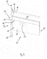
- Fig. 3 is a schematic perspective view of a section with partial removed elements of the panel shutter 10 according to the invention.
- the transmitter 25 emits a detection signal 30 parallel to the plane of the at least partial closed door blade 11 to the receiver 28 (not shown).
- the deformation 22 is below the detection signal 30. As the detection signal 30 is not interrupted by the deformation 22 a movement of the door blade 11 for unrolling or up rolling the door blade 11 is feasible.
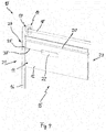
- Fig. 4 is a further schematic perspective view of a section with partial removed elements of the panel shutter 10 according to the invention.
- the door blade 11 has been moved upwards to up roll the door blade 11 around the coiling device 14.
- the deformation 22 of the shutter element 12 crosses the pathway of the detection signal 30.
- the detection signal 30 from the transmitter 25 to the receiver 28 is interrupted.
- the controller 26 (not shown) causes the drive 17 to stop.
- the vertical distance from the transmitter 25, the receiver 28 and the detection signal 30 to the upper end of the doorway 15 is such that the movement of the door blade 11 stops before the deformation 22 may hit the lintel profile 20.
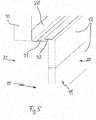
- Fig. 5 is a schematic perspective view of a detail at an upper end of doorway 15 of the panel shutter 10 according to the invention.
- the lower end of the lintel profile 20 defines the upper end of doorway 15.
- the lintel profile 20 is mounted to the lintel 33 of a wall. Between the lintel profile 20 and the door blade 11 or the upper shutter element 12 is a horizontal gap. This gap is closed by two sealing profiles 31, 32 when the door blade 11 is in its lowest position for totally blocking the doorway 15.
- a lintel sealing profile 31 is mounted to the lintel profile 20.
- the lintel sealing profile 31 is extending substantially horizontally from the lintel profile 20 towards the door blade 11.
- a door blade sealing profile 32 is mounted to the upper end of the door blade 11.
- the door blade sealing profile 32 is extending substantially horizontally from the upper end of the door blade 11 towards the lintel profile 20.
- a wind load or pressure on the inner side 23 of the door blade 11 lead to a deflection of the door blade 11 or the shutter elements 12. Because of the horizontal gap between the lintel profile 20 and the door blade 11 in conjunction with the flexible lintel sealing profile 31 and the flexible door blade sealing profile 32 the door blade 11 can pass the lintel profile 20 without contacting it.
- the door blade 11 or the shutter element 12 has a deformation 22 which extends to the outside in a range smaller than the gap between the lintel profile 20 and the door blade 11, preferably without any additional wind load acting on the inner side 23, the door blade 11 can still be rolled up as long as the deformation 22 does not interrupt the detection signal 30.
- the detection arrangement 24 may comprise in addition to the first transmitter 25 and the first receiver 26 at the outside of the panel shutter 10 a second transmitter and a second receiver.
- the second transmitter and the second receiver may be identical to the first transmitter 24 and the first receiver 26 respectively.
- the second transmitter and second receiver are arranged on the inner side 23 of the panel shutter 10.
- the second transmitter and second receiver are arranged to detect a deformation of a shutter element 12 extending to the inner side 23 or out of the inside of door blade 11.
- Such a deformation 22 may be caused by a collision with an object, for example a fork lift, which has impacted the shutter element 12 at the outer side 21 of the panel shutter 10.
- the arrangements of the transmitter 25 and the receiver 26 may be interchanged such that the transmitter 25 is arranged at the second side rail 27 and the receiver 26 is arranged at the first side rail 16.
- the arrangements of the second transmitter and the second receiver may be also freely selected such that the second transmitter and second receiver may be arranged at the first side rail or second side rail respectively.
Landscapes
- Engineering & Computer Science (AREA)
- Structural Engineering (AREA)
- Architecture (AREA)
- Civil Engineering (AREA)
- Operating, Guiding And Securing Of Roll- Type Closing Members (AREA)
Claims (12)
- Panelrollladen zum Öffnen und Schließen einer Toröffnung (15), umfassend ein Torblatt (11) und zwei Seitenschienen (16, 27), wobei das Torblatt (11) mehrere starre Rollladenelemente (12) umfasst, die miteinander gelenkig verbunden sind und in den Seitenschienen (16, 27) geführt sind, ferner umfassend eine Erkennungsvorrichtung (24) mit einer Sende-Empfangsvorrichtung (25, 28) zum Erkennen einer Verformung (22) mindestens eines Rollladenelements (12), dadurch gekennzeichnet, dass
eine Sendevorrichtung (25) der Sende-Empfangsvorrichtung (25, 28) an einer Innenseite einer ersten der Seitenschienen (16) angeordnet ist,
eine Empfangsvorrichtung (28) der Sende-Empfangsvorrichtung (25, 28) an einer Innenseite einer zweiten der Seitenschienen (27) angeordnet ist, wobei die Sendevorrichtung (25) und die Empfangsvorrichtung (28) gegeneinander gedreht sind, um eine Verformung (22) mindestens eines Rollladenelements (12) in einer Toröffnung von einem Erkennungssignal (30) von der Sendevorrichtung (25) an die Empfangsvorrichtung (28) zu erkennen,
wobei die Sendevorrichtung (25) und die Empfangsvorrichtung (28) in den Seitenschienen (16, 27) um einen vordefinierten horizontalen Abstand zum Torblatt (11) in einer geschlossenen Position eingebettet sind, um eine vordefinierte Ablenkung eines Rollladenelements (12) zu ermöglichen, ohne erkannt zu werden. - Panelrollladen nach Anspruch 1, wobei der horizontale Abstand der Sendevorrichtung (25) und der Empfangsvorrichtung (28) zum Torblatt (11) in einer geschlossenen Position im Bereich von 10 mm bis 100 mm liegt, und ein horizontaler Abstand im Bereich von 30 mm bis 50 mm, insbesondere ein horizontaler Abstand von 40 mm, besonders bevorzugt ist.
- Panelrollladen nach nach Anspruch 1 oder 2, wobei die Sendevorrichtung (25) ausgerichtet ist, um ein zu einer Ebene eines geschlossenen Torblatts (11) im Wesentlichen paralleles Erkennungssignal (30) in Richtung der Empfangsvorrichtung (28) auszusenden.
- Panelrollladen nach Anspruch 1, wobei die Sende-Empfangsvorrichtung (25, 28) eine Sende-Empfangseinheit und einen Reflektor umfasst, wobei die Sende-Empfangseinheit an einer Innenseite der ersten Seitenschiene (16) angeordnet ist, und der Reflektor an einer Innenseite der zweiten Schiene (27) angeordnet ist, und der Reflektor zum Reflektieren eines von der Sendevorrichtung (25) empfangenen Erkennungssignals (30) zurück zum Empfangsvorrichtung (28) angeordnet ist.
- Panelrollladen nach einem der vorgehenden Ansprüche, wobei die Sendevorrichtung (25) und die Empfangsvorrichtung (28) an den Seitenschienen (16, 27) um einen vordefinierten vertikalen Abstand zu einem oberen Ende der Toröffnung (15) zum Realisieren eines Anhaltewegs angeordnet sind.
- Panelrollladen nach Anspruch 5, wobei der vertikale Abstand der Sendevorrichtung (25) und der Empfangsvorrichtung (28) zum oberen Ende der Toröffnung (15) im Bereich von 300 mm bis 1000 mm liegt, und ein vertikaler Abstand im Bereich von 400 mm bis 700 mm, insbesondere ein vertikaler Abstand von 500 mm, besonders bevorzugt ist.
- Panelrollladen nach einem der vorgehenden Ansprüche, wobei die Erkennungsvorrichtung (24) mit einer Steuervorrichtung (26) verbunden ist, die ausgelegt ist, um es der Sendevorrichtung (25) zu ermöglichen, ein Erkennungssignal auszusenden, und die Steuervorrichtung (26) zum Empfangen von Signalen von der Empfangsvorrichtung (28) ausgelegt ist.
- Panelrollladen nach Anspruch 7, wobei die Steuervorrichtung (26) eine Erkennungsreaktion steuert, falls eine Verformung (22) erkannt wird, und die Erkennungsreaktion ein Ton, ein Audioalarm, ein Lichtsignal und/oder ein Stoppen jeder Bewegung des Torblatts (11) ist.
- Panelrollladen nach einem der vorgehenden Ansprüche, wobei die Erkennungsvorrichtung (24) an der Außenseite (21) der Toröffnung (15) zum Erkennen einer sich nach außen erstreckenden Verformung (22) angeordnet ist, und eine zweite Sende-Empfangsvorrichtung an der Innenseite (23) der Toröffnung (15) zum Erkennen einer sich nach innen erstreckenden Verformung angeordnet ist.
- Panelrollladen nach einem der vorgehenden Ansprüche, wobei ein Erkennungssignal (30) der Erkennungsvorrichtung (24) eine elektromagnetische Welle, ein Lichtstrahl, ein Infrarotstrahl oder ein Ultraschallstrahl ist.
- Panelrollladen nach einem der vorgehenden Ansprüche, wobei die Rollladenelemente (12) als Panele und/oder Lamellen gebildet sind, die zum Auf- und Abrollen des Torblatts um eine Aufrollvorrichtung (14) herum durch flexible Verbindungen (13) miteinander verbunden sind.
- Panelrollladen nach einem der vorgehenden Ansprüche, wobei der Panelrollladen (10) ein Schnelllauf-Rolltor ist, bevorzugt wobei im Normalbetrieb das Torblatt (11) des Schnelllauf-Rolltores mit einer Geschwindigkeit im Bereich von 0,5 m/s bis 5 m/s bewegt wird.
Applications Claiming Priority (2)
| Application Number | Priority Date | Filing Date | Title |
|---|---|---|---|
| SE1450205 | 2014-02-19 | ||
| PCT/EP2015/053321 WO2015124572A1 (en) | 2014-02-19 | 2015-02-17 | Panel shutter with a deformation detection arrangement |
Publications (2)
| Publication Number | Publication Date |
|---|---|
| EP3108084A1 EP3108084A1 (de) | 2016-12-28 |
| EP3108084B1 true EP3108084B1 (de) | 2020-06-03 |
Family
ID=52472338
Family Applications (1)
| Application Number | Title | Priority Date | Filing Date |
|---|---|---|---|
| EP15704573.3A Active EP3108084B1 (de) | 2014-02-19 | 2015-02-17 | Tor mit einer verformungserkennungsanordnung |
Country Status (5)
| Country | Link |
|---|---|
| US (1) | US20160348429A1 (de) |
| EP (1) | EP3108084B1 (de) |
| AU (1) | AU2015220951B2 (de) |
| CA (1) | CA2935684C (de) |
| WO (1) | WO2015124572A1 (de) |
Families Citing this family (12)
| Publication number | Priority date | Publication date | Assignee | Title |
|---|---|---|---|---|
| CA2948588C (en) * | 2014-06-26 | 2022-06-14 | Assa Abloy Entrance Systems Ab | Sealing device for sealing a gap between a lintel and a roller shutter and a roller shutter with such a sealing device |
| US10619397B2 (en) * | 2015-09-14 | 2020-04-14 | Rytec Corporation | System and method for safety management in roll-up doors |
| US12404714B2 (en) | 2015-09-14 | 2025-09-02 | Rytec Corporation | System and method for safety management in roll-up doors |
| SI3263820T1 (sl) * | 2016-06-28 | 2019-02-28 | Gabrijel Rejc | Motorno gnana in navpično premična dvižna vrata |
| EP3263819B1 (de) * | 2016-06-28 | 2018-12-19 | Gabrijel Rejc | Vertikal bewegbares tor mit einem torblatt |
| DE102016225079A1 (de) | 2016-12-15 | 2018-06-21 | Gabrijel Rejc Gmbh & Co. Kg | Tor mit einer Absturzsicherung |
| EP3899186A4 (de) | 2018-12-21 | 2022-10-05 | Rytec Corporation | Sicherheitssystem und -verfahren für rolltore |
| CN110067197B (zh) * | 2019-05-27 | 2021-01-05 | 江苏工程职业技术学院 | 一种爬壁型桥梁风压报警机器人及控制方法 |
| WO2021050540A2 (en) | 2019-09-09 | 2021-03-18 | Rite-Hite Holding Corporation | Apparatus and methods for door curtain breakaway detection |
| GB2603134B (en) * | 2021-01-27 | 2025-04-09 | Clark Door Ltd | Door Assembly |
| WO2022235891A1 (en) * | 2021-05-07 | 2022-11-10 | Rite-Hite Holding Corporation | Methods and apparatus to monitor and/or adjust operations of doors |
| WO2022236091A2 (en) * | 2021-05-07 | 2022-11-10 | Rite-Hite Holding Corporation | Methods and apparatus to operate powered doors |
Family Cites Families (12)
| Publication number | Priority date | Publication date | Assignee | Title |
|---|---|---|---|---|
| US5357183A (en) * | 1992-02-07 | 1994-10-18 | Lin Chii C | Automatic control and safety device for garage door opener |
| DK0764758T3 (da) * | 1995-08-24 | 2000-12-11 | Hoermann Kg Dissen | Hejseport med gitter |
| US6732476B2 (en) * | 2002-02-12 | 2004-05-11 | The Chamberlain Group, Inc. | Wireless barrier-edge monitor method |
| US20040188037A1 (en) * | 2003-03-31 | 2004-09-30 | Creative Extruded Products, Inc. | Retention system for pivotally connected shutter slats |
| DE102004030489A1 (de) * | 2004-06-24 | 2006-02-02 | Fraba Vitector Gmbh | Sicherheitsschaltleiste |
| FR2883584B1 (fr) * | 2005-03-25 | 2007-06-08 | Maviflex Sa Sa | Dispositif de detection d'un obstacle et de limitation d'effort d'un tablier d'une porte de manutention |
| DE102006018637B4 (de) * | 2006-04-21 | 2011-05-12 | Manfred Seysen | Schnelllauftor |
| US7592767B2 (en) * | 2007-03-14 | 2009-09-22 | Wayne-Dalton Corp. | System and related methods for diagnosing operational performance of a motorized barrier operator |
| FR2931866B1 (fr) * | 2008-05-28 | 2010-06-18 | Nergeco Sa | Porte a rideau souple incorporant une detection d'obstacle |
| EP2374985A3 (de) * | 2010-04-08 | 2014-10-01 | Strack Lift Automation GmbH | Motorisch angetriebenes Tor mit einer Sicherheitseinrichtung |
| US9284775B2 (en) * | 2011-10-31 | 2016-03-15 | Automatic Technology (Australia) Pty Ltd | Safety system for moveable closures |
| DE202012006155U1 (de) * | 2012-06-21 | 2012-07-20 | Jörg Brech | Optische Sicherung der Aufrollvorrichtungen von Industrietoren |
-
2015
- 2015-02-17 EP EP15704573.3A patent/EP3108084B1/de active Active
- 2015-02-17 AU AU2015220951A patent/AU2015220951B2/en active Active
- 2015-02-17 WO PCT/EP2015/053321 patent/WO2015124572A1/en not_active Ceased
- 2015-02-17 US US15/108,330 patent/US20160348429A1/en not_active Abandoned
- 2015-02-17 CA CA2935684A patent/CA2935684C/en active Active
Non-Patent Citations (1)
| Title |
|---|
| None * |
Also Published As
| Publication number | Publication date |
|---|---|
| EP3108084A1 (de) | 2016-12-28 |
| AU2015220951B2 (en) | 2019-01-24 |
| AU2015220951A1 (en) | 2016-07-21 |
| CA2935684C (en) | 2022-03-29 |
| WO2015124572A1 (en) | 2015-08-27 |
| CA2935684A1 (en) | 2015-08-27 |
| US20160348429A1 (en) | 2016-12-01 |
Similar Documents
| Publication | Publication Date | Title |
|---|---|---|
| EP3108084B1 (de) | Tor mit einer verformungserkennungsanordnung | |
| CA2936526C (en) | Fast roll-up door comprising a curtain speed detection device | |
| US20180002980A1 (en) | Method for controlling a door arrangement, as well as a door arrangement of this kind and a safety device therefor | |
| US9212028B2 (en) | Obstruction sensor system and method for elevator entry and exit | |
| AU2017288991A1 (en) | Safety door with ultrasonic detectors | |
| GB2573266A (en) | Safety device | |
| US8069897B2 (en) | Fast door with contact detecting means | |
| US20100236725A1 (en) | Fast door with flexible screen | |
| KR101833878B1 (ko) | 무레일 슬라이딩 게이트 | |
| DK2589991T3 (en) | Safety profile list with light grid | |
| EP3306026B1 (de) | Rolltor | |
| EP1722059B1 (de) | Sektionaltor | |
| EP4227481A1 (de) | Türmontage für eine doppeltür und zugehörige verriegelungsmethode | |
| JP2008088734A (ja) | 開閉装置 | |
| US20240052691A1 (en) | Roll door unit, roll-up door and use of a roll door unit for covering a door opening | |
| US20200240855A1 (en) | Object deformation detection using capacitive sensing | |
| JP4647357B2 (ja) | 回転ドアの安全装置 | |
| JP2020139271A (ja) | 防護装置、自動ドアシステムおよび防護装置の可動方法 | |
| JP4809012B2 (ja) | 開閉装置 | |
| KR20200059710A (ko) | 확장된 장애물 방지판을 가진 스크린 도어 장치 | |
| PT764758E (pt) | Portao de enrolar com colgadura em forma de grade | |
| JP2002339673A (ja) | 開閉装置 | |
| JP4221276B2 (ja) | 開閉装置用障害物感知構造及び該開閉装置用障害物感知構造を用いた開閉装置 | |
| JP4879949B2 (ja) | 開閉装置用障害物感知構造 | |
| JP4261318B2 (ja) | 開閉装置用障害物感知構造 |
Legal Events
| Date | Code | Title | Description |
|---|---|---|---|
| PUAI | Public reference made under article 153(3) epc to a published international application that has entered the european phase |
Free format text: ORIGINAL CODE: 0009012 |
|
| STAA | Information on the status of an ep patent application or granted ep patent |
Free format text: STATUS: REQUEST FOR EXAMINATION WAS MADE |
|
| 17P | Request for examination filed |
Effective date: 20160706 |
|
| AK | Designated contracting states |
Kind code of ref document: A1 Designated state(s): AL AT BE BG CH CY CZ DE DK EE ES FI FR GB GR HR HU IE IS IT LI LT LU LV MC MK MT NL NO PL PT RO RS SE SI SK SM TR |
|
| AX | Request for extension of the european patent |
Extension state: BA ME |
|
| DAX | Request for extension of the european patent (deleted) | ||
| STAA | Information on the status of an ep patent application or granted ep patent |
Free format text: STATUS: EXAMINATION IS IN PROGRESS |
|
| 17Q | First examination report despatched |
Effective date: 20170814 |
|
| GRAP | Despatch of communication of intention to grant a patent |
Free format text: ORIGINAL CODE: EPIDOSNIGR1 |
|
| STAA | Information on the status of an ep patent application or granted ep patent |
Free format text: STATUS: GRANT OF PATENT IS INTENDED |
|
| RIC1 | Information provided on ipc code assigned before grant |
Ipc: E06B 9/88 20060101AFI20191220BHEP Ipc: E06B 9/17 20060101ALN20191220BHEP Ipc: E06B 9/68 20060101ALN20191220BHEP |
|
| INTG | Intention to grant announced |
Effective date: 20200123 |
|
| GRAS | Grant fee paid |
Free format text: ORIGINAL CODE: EPIDOSNIGR3 |
|
| GRAA | (expected) grant |
Free format text: ORIGINAL CODE: 0009210 |
|
| STAA | Information on the status of an ep patent application or granted ep patent |
Free format text: STATUS: THE PATENT HAS BEEN GRANTED |
|
| AK | Designated contracting states |
Kind code of ref document: B1 Designated state(s): AL AT BE BG CH CY CZ DE DK EE ES FI FR GB GR HR HU IE IS IT LI LT LU LV MC MK MT NL NO PL PT RO RS SE SI SK SM TR |
|
| REG | Reference to a national code |
Ref country code: GB Ref legal event code: FG4D |
|
| REG | Reference to a national code |
Ref country code: AT Ref legal event code: REF Ref document number: 1277190 Country of ref document: AT Kind code of ref document: T Effective date: 20200615 Ref country code: CH Ref legal event code: EP |
|
| REG | Reference to a national code |
Ref country code: DE Ref legal event code: R096 Ref document number: 602015053692 Country of ref document: DE |
|
| REG | Reference to a national code |
Ref country code: LT Ref legal event code: MG4D |
|
| PG25 | Lapsed in a contracting state [announced via postgrant information from national office to epo] |
Ref country code: FI Free format text: LAPSE BECAUSE OF FAILURE TO SUBMIT A TRANSLATION OF THE DESCRIPTION OR TO PAY THE FEE WITHIN THE PRESCRIBED TIME-LIMIT Effective date: 20200603 Ref country code: NO Free format text: LAPSE BECAUSE OF FAILURE TO SUBMIT A TRANSLATION OF THE DESCRIPTION OR TO PAY THE FEE WITHIN THE PRESCRIBED TIME-LIMIT Effective date: 20200903 Ref country code: GR Free format text: LAPSE BECAUSE OF FAILURE TO SUBMIT A TRANSLATION OF THE DESCRIPTION OR TO PAY THE FEE WITHIN THE PRESCRIBED TIME-LIMIT Effective date: 20200904 Ref country code: LT Free format text: LAPSE BECAUSE OF FAILURE TO SUBMIT A TRANSLATION OF THE DESCRIPTION OR TO PAY THE FEE WITHIN THE PRESCRIBED TIME-LIMIT Effective date: 20200603 Ref country code: SE Free format text: LAPSE BECAUSE OF FAILURE TO SUBMIT A TRANSLATION OF THE DESCRIPTION OR TO PAY THE FEE WITHIN THE PRESCRIBED TIME-LIMIT Effective date: 20200603 |
|
| REG | Reference to a national code |
Ref country code: NL Ref legal event code: MP Effective date: 20200603 |
|
| PG25 | Lapsed in a contracting state [announced via postgrant information from national office to epo] |
Ref country code: BG Free format text: LAPSE BECAUSE OF FAILURE TO SUBMIT A TRANSLATION OF THE DESCRIPTION OR TO PAY THE FEE WITHIN THE PRESCRIBED TIME-LIMIT Effective date: 20200903 Ref country code: HR Free format text: LAPSE BECAUSE OF FAILURE TO SUBMIT A TRANSLATION OF THE DESCRIPTION OR TO PAY THE FEE WITHIN THE PRESCRIBED TIME-LIMIT Effective date: 20200603 Ref country code: RS Free format text: LAPSE BECAUSE OF FAILURE TO SUBMIT A TRANSLATION OF THE DESCRIPTION OR TO PAY THE FEE WITHIN THE PRESCRIBED TIME-LIMIT Effective date: 20200603 Ref country code: LV Free format text: LAPSE BECAUSE OF FAILURE TO SUBMIT A TRANSLATION OF THE DESCRIPTION OR TO PAY THE FEE WITHIN THE PRESCRIBED TIME-LIMIT Effective date: 20200603 |
|
| REG | Reference to a national code |
Ref country code: AT Ref legal event code: MK05 Ref document number: 1277190 Country of ref document: AT Kind code of ref document: T Effective date: 20200603 |
|
| PG25 | Lapsed in a contracting state [announced via postgrant information from national office to epo] |
Ref country code: AL Free format text: LAPSE BECAUSE OF FAILURE TO SUBMIT A TRANSLATION OF THE DESCRIPTION OR TO PAY THE FEE WITHIN THE PRESCRIBED TIME-LIMIT Effective date: 20200603 Ref country code: NL Free format text: LAPSE BECAUSE OF FAILURE TO SUBMIT A TRANSLATION OF THE DESCRIPTION OR TO PAY THE FEE WITHIN THE PRESCRIBED TIME-LIMIT Effective date: 20200603 |
|
| PG25 | Lapsed in a contracting state [announced via postgrant information from national office to epo] |
Ref country code: RO Free format text: LAPSE BECAUSE OF FAILURE TO SUBMIT A TRANSLATION OF THE DESCRIPTION OR TO PAY THE FEE WITHIN THE PRESCRIBED TIME-LIMIT Effective date: 20200603 Ref country code: SM Free format text: LAPSE BECAUSE OF FAILURE TO SUBMIT A TRANSLATION OF THE DESCRIPTION OR TO PAY THE FEE WITHIN THE PRESCRIBED TIME-LIMIT Effective date: 20200603 Ref country code: ES Free format text: LAPSE BECAUSE OF FAILURE TO SUBMIT A TRANSLATION OF THE DESCRIPTION OR TO PAY THE FEE WITHIN THE PRESCRIBED TIME-LIMIT Effective date: 20200603 Ref country code: EE Free format text: LAPSE BECAUSE OF FAILURE TO SUBMIT A TRANSLATION OF THE DESCRIPTION OR TO PAY THE FEE WITHIN THE PRESCRIBED TIME-LIMIT Effective date: 20200603 Ref country code: AT Free format text: LAPSE BECAUSE OF FAILURE TO SUBMIT A TRANSLATION OF THE DESCRIPTION OR TO PAY THE FEE WITHIN THE PRESCRIBED TIME-LIMIT Effective date: 20200603 Ref country code: PT Free format text: LAPSE BECAUSE OF FAILURE TO SUBMIT A TRANSLATION OF THE DESCRIPTION OR TO PAY THE FEE WITHIN THE PRESCRIBED TIME-LIMIT Effective date: 20201006 Ref country code: CZ Free format text: LAPSE BECAUSE OF FAILURE TO SUBMIT A TRANSLATION OF THE DESCRIPTION OR TO PAY THE FEE WITHIN THE PRESCRIBED TIME-LIMIT Effective date: 20200603 Ref country code: IT Free format text: LAPSE BECAUSE OF FAILURE TO SUBMIT A TRANSLATION OF THE DESCRIPTION OR TO PAY THE FEE WITHIN THE PRESCRIBED TIME-LIMIT Effective date: 20200603 |
|
| PG25 | Lapsed in a contracting state [announced via postgrant information from national office to epo] |
Ref country code: IS Free format text: LAPSE BECAUSE OF FAILURE TO SUBMIT A TRANSLATION OF THE DESCRIPTION OR TO PAY THE FEE WITHIN THE PRESCRIBED TIME-LIMIT Effective date: 20201003 Ref country code: SK Free format text: LAPSE BECAUSE OF FAILURE TO SUBMIT A TRANSLATION OF THE DESCRIPTION OR TO PAY THE FEE WITHIN THE PRESCRIBED TIME-LIMIT Effective date: 20200603 Ref country code: PL Free format text: LAPSE BECAUSE OF FAILURE TO SUBMIT A TRANSLATION OF THE DESCRIPTION OR TO PAY THE FEE WITHIN THE PRESCRIBED TIME-LIMIT Effective date: 20200603 |
|
| REG | Reference to a national code |
Ref country code: DE Ref legal event code: R097 Ref document number: 602015053692 Country of ref document: DE |
|
| PLBE | No opposition filed within time limit |
Free format text: ORIGINAL CODE: 0009261 |
|
| STAA | Information on the status of an ep patent application or granted ep patent |
Free format text: STATUS: NO OPPOSITION FILED WITHIN TIME LIMIT |
|
| PG25 | Lapsed in a contracting state [announced via postgrant information from national office to epo] |
Ref country code: DK Free format text: LAPSE BECAUSE OF FAILURE TO SUBMIT A TRANSLATION OF THE DESCRIPTION OR TO PAY THE FEE WITHIN THE PRESCRIBED TIME-LIMIT Effective date: 20200603 |
|
| 26N | No opposition filed |
Effective date: 20210304 |
|
| PG25 | Lapsed in a contracting state [announced via postgrant information from national office to epo] |
Ref country code: SI Free format text: LAPSE BECAUSE OF FAILURE TO SUBMIT A TRANSLATION OF THE DESCRIPTION OR TO PAY THE FEE WITHIN THE PRESCRIBED TIME-LIMIT Effective date: 20200603 |
|
| PG25 | Lapsed in a contracting state [announced via postgrant information from national office to epo] |
Ref country code: MC Free format text: LAPSE BECAUSE OF FAILURE TO SUBMIT A TRANSLATION OF THE DESCRIPTION OR TO PAY THE FEE WITHIN THE PRESCRIBED TIME-LIMIT Effective date: 20200603 |
|
| REG | Reference to a national code |
Ref country code: BE Ref legal event code: MM Effective date: 20210228 |
|
| PG25 | Lapsed in a contracting state [announced via postgrant information from national office to epo] |
Ref country code: CH Free format text: LAPSE BECAUSE OF NON-PAYMENT OF DUE FEES Effective date: 20210228 Ref country code: LU Free format text: LAPSE BECAUSE OF NON-PAYMENT OF DUE FEES Effective date: 20210217 Ref country code: LI Free format text: LAPSE BECAUSE OF NON-PAYMENT OF DUE FEES Effective date: 20210228 |
|
| PG25 | Lapsed in a contracting state [announced via postgrant information from national office to epo] |
Ref country code: IE Free format text: LAPSE BECAUSE OF NON-PAYMENT OF DUE FEES Effective date: 20210217 |
|
| PG25 | Lapsed in a contracting state [announced via postgrant information from national office to epo] |
Ref country code: BE Free format text: LAPSE BECAUSE OF NON-PAYMENT OF DUE FEES Effective date: 20210228 |
|
| PG25 | Lapsed in a contracting state [announced via postgrant information from national office to epo] |
Ref country code: HU Free format text: LAPSE BECAUSE OF FAILURE TO SUBMIT A TRANSLATION OF THE DESCRIPTION OR TO PAY THE FEE WITHIN THE PRESCRIBED TIME-LIMIT; INVALID AB INITIO Effective date: 20150217 |
|
| PG25 | Lapsed in a contracting state [announced via postgrant information from national office to epo] |
Ref country code: CY Free format text: LAPSE BECAUSE OF FAILURE TO SUBMIT A TRANSLATION OF THE DESCRIPTION OR TO PAY THE FEE WITHIN THE PRESCRIBED TIME-LIMIT Effective date: 20200603 |
|
| P01 | Opt-out of the competence of the unified patent court (upc) registered |
Effective date: 20230530 |
|
| PG25 | Lapsed in a contracting state [announced via postgrant information from national office to epo] |
Ref country code: MK Free format text: LAPSE BECAUSE OF FAILURE TO SUBMIT A TRANSLATION OF THE DESCRIPTION OR TO PAY THE FEE WITHIN THE PRESCRIBED TIME-LIMIT Effective date: 20200603 |
|
| PG25 | Lapsed in a contracting state [announced via postgrant information from national office to epo] |
Ref country code: TR Free format text: LAPSE BECAUSE OF FAILURE TO SUBMIT A TRANSLATION OF THE DESCRIPTION OR TO PAY THE FEE WITHIN THE PRESCRIBED TIME-LIMIT Effective date: 20200603 |
|
| PG25 | Lapsed in a contracting state [announced via postgrant information from national office to epo] |
Ref country code: MT Free format text: LAPSE BECAUSE OF FAILURE TO SUBMIT A TRANSLATION OF THE DESCRIPTION OR TO PAY THE FEE WITHIN THE PRESCRIBED TIME-LIMIT Effective date: 20200603 |
|
| PGFP | Annual fee paid to national office [announced via postgrant information from national office to epo] |
Ref country code: GB Payment date: 20260112 Year of fee payment: 12 |
|
| PGFP | Annual fee paid to national office [announced via postgrant information from national office to epo] |
Ref country code: DE Payment date: 20260114 Year of fee payment: 12 |
|
| PGFP | Annual fee paid to national office [announced via postgrant information from national office to epo] |
Ref country code: FR Payment date: 20260121 Year of fee payment: 12 |