EP3108154B2 - Procédé permettant de faire fonctionner une chaîne d'entraînement et de transmission et chaîne d'entraînement et de transmission - Google Patents
Procédé permettant de faire fonctionner une chaîne d'entraînement et de transmission et chaîne d'entraînement et de transmission Download PDFInfo
- Publication number
- EP3108154B2 EP3108154B2 EP14733962.6A EP14733962A EP3108154B2 EP 3108154 B2 EP3108154 B2 EP 3108154B2 EP 14733962 A EP14733962 A EP 14733962A EP 3108154 B2 EP3108154 B2 EP 3108154B2
- Authority
- EP
- European Patent Office
- Prior art keywords
- drive
- differential
- speed
- machine
- gear
- Prior art date
- Legal status (The legal status is an assumption and is not a legal conclusion. Google has not performed a legal analysis and makes no representation as to the accuracy of the status listed.)
- Active
Links
Images



Classifications
-
- G—PHYSICS
- G05—CONTROLLING; REGULATING
- G05D—SYSTEMS FOR CONTROLLING OR REGULATING NON-ELECTRIC VARIABLES
- G05D13/00—Control of linear speed; Control of angular speed; Control of acceleration or deceleration, e.g. of a prime mover
- G05D13/64—Compensating the speed difference between engines meshing by a differential gearing or the speed difference between a controlling shaft and a controlled shaft
-
- F—MECHANICAL ENGINEERING; LIGHTING; HEATING; WEAPONS; BLASTING
- F16—ENGINEERING ELEMENTS AND UNITS; GENERAL MEASURES FOR PRODUCING AND MAINTAINING EFFECTIVE FUNCTIONING OF MACHINES OR INSTALLATIONS; THERMAL INSULATION IN GENERAL
- F16H—GEARING
- F16H3/00—Toothed gearings for conveying rotary motion with variable gear ratio or for reversing rotary motion
- F16H3/44—Toothed gearings for conveying rotary motion with variable gear ratio or for reversing rotary motion using gears having orbital motion
- F16H3/72—Toothed gearings for conveying rotary motion with variable gear ratio or for reversing rotary motion using gears having orbital motion with a secondary drive, e.g. regulating motor, in order to vary speed continuously
- F16H3/724—Toothed gearings for conveying rotary motion with variable gear ratio or for reversing rotary motion using gears having orbital motion with a secondary drive, e.g. regulating motor, in order to vary speed continuously using externally powered electric machines
-
- F—MECHANICAL ENGINEERING; LIGHTING; HEATING; WEAPONS; BLASTING
- F03—MACHINES OR ENGINES FOR LIQUIDS; WIND, SPRING, OR WEIGHT MOTORS; PRODUCING MECHANICAL POWER OR A REACTIVE PROPULSIVE THRUST, NOT OTHERWISE PROVIDED FOR
- F03D—WIND MOTORS
- F03D15/00—Transmission of mechanical power
-
- F—MECHANICAL ENGINEERING; LIGHTING; HEATING; WEAPONS; BLASTING
- F03—MACHINES OR ENGINES FOR LIQUIDS; WIND, SPRING, OR WEIGHT MOTORS; PRODUCING MECHANICAL POWER OR A REACTIVE PROPULSIVE THRUST, NOT OTHERWISE PROVIDED FOR
- F03D—WIND MOTORS
- F03D15/00—Transmission of mechanical power
- F03D15/10—Transmission of mechanical power using gearing not limited to rotary motion, e.g. with oscillating or reciprocating members
-
- F—MECHANICAL ENGINEERING; LIGHTING; HEATING; WEAPONS; BLASTING
- F03—MACHINES OR ENGINES FOR LIQUIDS; WIND, SPRING, OR WEIGHT MOTORS; PRODUCING MECHANICAL POWER OR A REACTIVE PROPULSIVE THRUST, NOT OTHERWISE PROVIDED FOR
- F03D—WIND MOTORS
- F03D7/00—Controlling wind motors
- F03D7/02—Controlling wind motors the wind motors having rotation axis substantially parallel to the air flow entering the rotor
- F03D7/0276—Controlling wind motors the wind motors having rotation axis substantially parallel to the air flow entering the rotor controlling rotor speed, e.g. variable speed
-
- F—MECHANICAL ENGINEERING; LIGHTING; HEATING; WEAPONS; BLASTING
- F03—MACHINES OR ENGINES FOR LIQUIDS; WIND, SPRING, OR WEIGHT MOTORS; PRODUCING MECHANICAL POWER OR A REACTIVE PROPULSIVE THRUST, NOT OTHERWISE PROVIDED FOR
- F03D—WIND MOTORS
- F03D7/00—Controlling wind motors
- F03D7/02—Controlling wind motors the wind motors having rotation axis substantially parallel to the air flow entering the rotor
- F03D7/04—Automatic control; Regulation
-
- F—MECHANICAL ENGINEERING; LIGHTING; HEATING; WEAPONS; BLASTING
- F03—MACHINES OR ENGINES FOR LIQUIDS; WIND, SPRING, OR WEIGHT MOTORS; PRODUCING MECHANICAL POWER OR A REACTIVE PROPULSIVE THRUST, NOT OTHERWISE PROVIDED FOR
- F03D—WIND MOTORS
- F03D9/00—Adaptations of wind motors for special use; Combinations of wind motors with apparatus driven thereby; Wind motors specially adapted for installation in particular locations
- F03D9/20—Wind motors characterised by the driven apparatus
- F03D9/25—Wind motors characterised by the driven apparatus the apparatus being an electrical generator
- F03D9/255—Wind motors characterised by the driven apparatus the apparatus being an electrical generator connected to electrical distribution networks; Arrangements therefor
-
- H—ELECTRICITY
- H02—GENERATION; CONVERSION OR DISTRIBUTION OF ELECTRIC POWER
- H02P—CONTROL OR REGULATION OF ELECTRIC MOTORS, ELECTRIC GENERATORS OR DYNAMO-ELECTRIC CONVERTERS; CONTROLLING TRANSFORMERS, REACTORS OR CHOKE COILS
- H02P9/00—Arrangements for controlling electric generators for the purpose of obtaining a desired output
-
- F—MECHANICAL ENGINEERING; LIGHTING; HEATING; WEAPONS; BLASTING
- F05—INDEXING SCHEMES RELATING TO ENGINES OR PUMPS IN VARIOUS SUBCLASSES OF CLASSES F01-F04
- F05B—INDEXING SCHEME RELATING TO WIND, SPRING, WEIGHT, INERTIA OR LIKE MOTORS, TO MACHINES OR ENGINES FOR LIQUIDS COVERED BY SUBCLASSES F03B, F03D AND F03G
- F05B2260/00—Function
- F05B2260/40—Transmission of power
- F05B2260/403—Transmission of power through the shape of the drive components
- F05B2260/4031—Transmission of power through the shape of the drive components as in toothed gearing
- F05B2260/40311—Transmission of power through the shape of the drive components as in toothed gearing of the epicyclic, planetary or differential type
-
- Y—GENERAL TAGGING OF NEW TECHNOLOGICAL DEVELOPMENTS; GENERAL TAGGING OF CROSS-SECTIONAL TECHNOLOGIES SPANNING OVER SEVERAL SECTIONS OF THE IPC; TECHNICAL SUBJECTS COVERED BY FORMER USPC CROSS-REFERENCE ART COLLECTIONS [XRACs] AND DIGESTS
- Y02—TECHNOLOGIES OR APPLICATIONS FOR MITIGATION OR ADAPTATION AGAINST CLIMATE CHANGE
- Y02E—REDUCTION OF GREENHOUSE GAS [GHG] EMISSIONS, RELATED TO ENERGY GENERATION, TRANSMISSION OR DISTRIBUTION
- Y02E10/00—Energy generation through renewable energy sources
- Y02E10/70—Wind energy
- Y02E10/72—Wind turbines with rotation axis in wind direction
Definitions
- the invention relates to a method for operating a drive train with a drive shaft, an electric drive machine connected to a power grid, operable as a motor and generator, and with a differential gear with three input and output drives, wherein one output is connected to the drive shaft, a drive is connected to the drive machine, and a second drive is connected to a differential drive.
- the invention further relates to a drive train with a drive shaft, an electric drive machine connected to a power grid, operable as a motor and generator, and with a differential gear with three input and output drives, one output being connected to the drive shaft, one drive to the drive machine, and a second drive to an electric differential drive.
- WO 2010/101467 A discloses a drive train for a vehicle, with a differential and two electric machines, which can be operated either as a motor or as a generator.
- a general problem of working machines is efficient variable speed operation.
- electric machines are used as an example of drive machines, but the principle applies to all possible types of drive machines, such as internal combustion engines.
- the most commonly used electric drives today are three-phase machines, such as asynchronous motors and synchronous motors.
- the invention is based on the object of specifying a method and a device of the type mentioned at the outset, in which a change in the delivery rate of the conveying device is possible with a simple structure.
- the core of a differential system is a differential gear, which in a simple design is a simple planetary gear stage with three inputs and outputs, with one output connected to the drive shaft of a working machine, a first drive to the drive machine and a second drive to a differential drive.
- This allows the working machine to be operated at variable speeds while the drive machine has a constant speed, as the differential drive compensates for the speed difference.
- the amount of material delivered by the working machine can be increased by increasing the constant power of the drive machine through the variable power of the differential drive.
- inverter usually used for an electric differential drive is replaced by a rectifier, this is advantageous because it usually has a higher efficiency than an inverter and is also much more robust and cost-effective.
- the invention can be used, for example, in storage power plants.
- a three-phase machine must therefore be designed to be large enough to be able to deliver a drive torque corresponding to the nominal torque from standstill, and is therefore often oversized. For this reason, instead of being connected directly to a network, electrical machines are often designed as a variable speed drive in combination with a frequency converter. This allows starting with a high torque from zero speed without putting a strain on the network, but the solution is expensive and involves significant losses in efficiency.
- the gear ratio of the differential gear can be set to 1.
- the differential drive can be used to drive the entire drive train or to bring the drive machine to synchronous speed and subsequently synchronize it with the network.
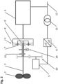
- Fig.1 shows the principle of a differential system not according to the invention for a drive train using the example of a pump.
- the working machine 1 is the rotor of a pump, which is driven by a drive machine 4 via a drive shaft 2 and a differential gear 3.
- the drive machine 4 is preferably a medium-voltage three-phase machine, which is connected to a network 12, which in the example shown is a medium-voltage network due to a medium-voltage three-phase machine.
- the selected voltage level depends on the application and in particular the performance level of the drive machine 4 and can have any desired voltage level without affecting the basic function of the system according to the invention.
- a design-specific operating speed range results according to the number of pole pairs of the drive machine 4.
- the operating speed range is the speed range in which the drive machine 4 can deliver a defined or desired or required torque or, in the case of an electric drive machine, can be synchronized with the network 12.
- a planet carrier 7 is connected to the drive shaft 2, a drive machine 4 to a ring gear 8 and a sun gear 9 of the differential gear 3 to the differential drive 5.
- the core of the differential system in this embodiment is thus a simple planetary gear stage with three inputs and outputs, with one output being connected to the drive shaft 2 of the working machine 1, a first drive to the drive machine 4 and a second drive to the differential drive 5.
- an adaptation gear 10 is implemented between the sun gear 9 and the differential drive 5.
- the adaptation gear 10 can also be multi-stage or designed as a toothed belt or chain drive.
- the adaptation gear 10 can also be used to implement an axis offset for the differential drive 5, which enables a simple design of the differential drive 5 due to the coaxial arrangement of the working machine 1 and the drive machine 4.
- a motor brake 13 is connected to the differential drive 5, which brakes the differential drive 5 when required.
- the differential drive 5 is electrically connected to the network 12 by means of a preferably low-voltage frequency converter, consisting of a motor-side inverter 6a and a network-side inverter 6b, and a transformer 11.
- the transformer compensates for any existing voltage differences between the network 12 and the network-side inverter 6b and can be omitted if the voltage between the drive machine 4, the network-side inverter 6b and the network 12 is the same.
- the inverters 6a and 6b are connected by a DC intermediate circuit and can be spatially separated if required, with the motor-side inverter 6a preferably being positioned as close as possible to the differential drive 5.
- the main advantage of this concept is that the drive machine 4 can be connected directly to a network 12, i.e. without complex power electronics.
- the balance between variable rotor speed and fixed speed of the network-connected drive machine 4 is achieved by the variable-speed differential drive 5.
- Torque Differential drive Torque Drive shaft * y/x , where the size factor y/x is a measure of the gear ratios in the differential gear 3 and in the adaptation gear 10.
- the power of the differential drive 5 is essentially proportional to the product of the percentage deviation of the pump speed from its base speed x drive shaft power. Accordingly, a large speed range basically requires a correspondingly large dimensioning of the differential drive 5. This is also the reason why differential systems are particularly well suited for small speed ranges, although in principle any speed range can be implemented.
- a differential drive 5 for a pump as a working machine 1 has an output of around 15% of the total system output. This in turn means that low speeds cannot be achieved on the working machine 1 with the differential system. If the working machine 1 has to be brought from zero speed with high torque into its working speed range (this is the speed range in which the working machine 1 essentially works), this can only be achieved by braking the differential drive 5 (either electrically or by means of the engine brake 13) and connecting the driving machine 4 to the mains. The working machine 4 in turn can only generate the nominal torque from a standstill with difficulty, or it draws up to 7 times the nominal current in order to accelerate to approximately synchronous speed.
- the starting current can be reduced, but this also reduces the achievable starting torque.
- An improvement can be achieved, for example, by bringing the differential drive 5 to its maximum possible operating speed at the beginning of the start-up. Due to external loads, the working machine 1 remains in a low speed range during this time. This brings the drive machine 4 to a speed which is inevitably set depending on the speed of the working machine 1 on the one hand and the gear ratio of the differential gear 3 and any existing adaptation gear 10 on the other.
- the differential drive 5 is then controlled so that its speed remains within its control speed range, while the drive machine 4 is connected to the network 12 with or without a so-called star/delta connection.
- the speed control or braking of the differential drive 5 is preferably carried out electrically by the inverter 6a, 6b, or by means of the motor brake 13.
- the engine brake 13 can also be used to protect the differential drive 5 from overspeeds if, for example, the drive machine 4 fails and the working machine 1 stops or rotates in the opposite direction.
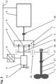
- Fig.2 shows another embodiment of a differential system.
- the drive train shown here also has Fig.1 a working machine 1, a drive shaft 2, a differential gear 3, a drive machine 4 and a differential drive 5, which is connected to the network 12 by means of a frequency converter 6 (consisting of motor-side and network-side inverters - shown here as a simplified unit) and a transformer 11.
- the differential drive 5 is connected to the differential gear 3 by means of an adaptation gear 10.
- a clutch is provided between the adaptation gear 10 and the differential gear 3. 15 implemented.
- a synchronization brake 14 acts on the sun gear 9 and thus on the entire drive train.
- the differential drive 5 and the adaptation gear 10 are decoupled from the rest of the drive train by the clutch 15 in a first step. If the drive machine 4 is now started up and connected to the network, the sun gear 9 rotates freely and no significant torque can build up in the entire drive train. In this case, too, the working machine 1 remains in a low speed range and the drive machine 4 can be synchronized with the network 12 without any significant external counter-torque.
- either a star/delta connection can be implemented or the drive machine 4 can be brought to (approximately) synchronous speed by an auxiliary device - e.g. a small variable speed drive - and then synchronized with the network 12.
- an auxiliary device e.g. a small variable speed drive - and then synchronized with the network 12.
- the clutch 15 closed - as already mentioned Fig.1 described - the drive machine 4 can be brought up to speed with the differential drive 5. In this case, the drive machine 4 cannot be accelerated to its synchronous speed, but at least the resulting starting current is smaller. The clutch 15 is then opened again.
- the control speed range is the speed range in which the differential drive 5 works in order to be able to realize the working speed range of the working machine 1.
- the control speed range is determined primarily by the voltage, current and speed limits specified by the manufacturer.
- the differential drive 5 cannot be connected to the mains 12.
- the synchronization brake 14 is used to decelerate the second drive of the differential gear 3 connected to the sun gear 9 to a speed that is in the control speed range of the differential drive 5.
- the part of the clutch 15 on the differential drive side (preferably by means of the differential drive 5) is preferably synchronized with the speed of the second drive of the differential gear 3 and then the clutch 15 is closed.
- the clutch 15 is preferably a positive-locking claw clutch or a non-positive multi-disk clutch.
- One advantage of the non-positive multi-disk clutch is that, if designed for this purpose, no synchronization of the two clutch halves is necessary.
- the multiple nominal torque can be realized as a starting torque from zero speed, since the typical breakdown moment of a three-phase machine is approximately 2 to 3 times its nominal torque.
- this starting method can also be used with internal combustion engines, for example, which is sometimes necessary because these can only generate a torque in the partial speed range that is significantly lower than their nominal torque.
- the synchronization brake 14 can therefore also basically take over the function of the Fig.1 shown engine brake 13.
- any type of brake can be used.
- retarders are particularly suitable here.
- Hydrodynamic retarders usually work with oil or water, which is fed into a converter housing when required.
- the converter housing consists of two rotationally symmetrical and opposing impellers, and before that a rotor that is connected to the drive train of the system, and a fixed stator.
- the rotor accelerates the supplied oil and the centrifugal force pushes it outwards.
- the shape of the rotor blades directs the oil into the stator, which induces a braking torque in the rotor and then brakes the entire drive train.
- electrodynamic retarder electric brake
- an eddy current brake two steel disks (rotors) that are not magnetized are connected to the drive train. In between is the stator with electrical coils. When current is supplied by activating the retarder, magnetic fields are generated which are closed by the rotors. The opposing magnetic fields then produce the braking effect. The heat generated is released again, for example, through internally ventilated rotor disks.
- a major advantage of a retarder as a service brake is its freedom from wear and good controllability.
- the system can also be used to operate the drive machine 4 in phase shift mode. This means that the drive machine 4 can supply or draw reactive power into or from the network 12 without the driven machine 1 being operated. This applies in particular to energy generation plants.
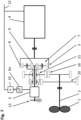
- Fig.3 shows a further embodiment of a differential system with a gear pre-stage 16.
- This gear pre-stage 16 allows the speed range for the drive shaft 2 or for the working machine 1 to be adjusted according to the gear ratio of the gear pre-stage 16.
- the use of a gear pre-stage 16 is then necessary or advantageous if the speed level resulting from the technical parameters of, for example, a cost-effective drive machine 4 and an efficient differential system does not correspond to the required working speed range of a working machine 1.
- a resulting advantage is that, if the gear pre-stage 16 is a spur gear stage as shown, the differential drive 5 can be operated without an adaptation gear 10 according to Fig.1 and 2 can be positioned coaxially to the drive machine 4 on the side of the differential gear 3 facing away from the drive machine.
- stepped planets instead of simple planets.
- These stepped planets each consist of two rotationally fixed gears with different diameters and preferably different tooth geometry.
- the ring gear 8 is then in mesh with the smaller diameter gear of the stepped planet, and the sun gear 9 with the second gear of the stepped planet.
- the connecting shaft 26 between the differential gear 3 and the differential drive 5 is preferably an electrically non-conductive fiber composite shaft. If the connecting shaft 26 is an electrically conductive shaft, then an insulating element should preferably be installed between the differential gear 3 (or, if present, the adaptation gear 10) and the differential drive 5 in order to keep unwanted electrical currents away from the differential gear 3.
- the differential system therefore consists of the smallest possible number of components and also has an optimal overall efficiency.
- the engine brake 13 also fulfils the function of the synchronization brake 14 from Fig.2 .
- Disadvantage of this embodiment compared to that according to Fig.2 is that the differential drive 5 must be designed for a higher speed for the starting process, whereby the differential drive 5 is preferably disconnected from the mains at speeds above the control speed range. This means that speeds outside the control speed range only have to be tolerated mechanically.
- the transmission ratio of the differential gear 3 must be higher than for the solution according to Fig.2 , because the adjustment gear 10 is missing here. In principle, however, the variant acc.
- Fig.3 the additional use of an adaptation gear 10 is possible, whereby the gear ratio of the differential gear 3 can be reduced.
- a clutch 15 and a synchronization brake 14 can also be implemented between the second drive of the differential gear 3 or sun gear 9 and the differential drive 5.
- a further advantage of this embodiment with gear pre-stage 16 is that a coaxial hollow shaft 27 to the working machine 1 can be implemented in a simple manner.
- the rotating working machine 1 can be supplied electrically or hydraulically in a simple manner using this hollow shaft 27.
- a rotary transmission 28 is preferably applied to the side of the gear pre-stage facing away from the working machine.
- a mechanical rod can also be guided in the passage 27 and thus the blades of a pump rotor, for example, can be mechanically adjusted by translatory or rotary movement.
- the drive shaft 2 and the drive motor 4 are preferably connected by means of a coupling 17, 18.
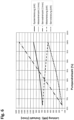
- Fig.4 shows the speed and performance parameters of a differential system not according to the invention, for example for a pump.
- the illustration shows performance and speed values for a pump as working machine 1, a drive machine 4 and a differential drive 5, each plotted against the speed values of the drive shaft 2 ("pump speed").
- the drive machine 4 is connected to the network 12 and thus its speed (“motor speed") is constant - in the example shown, approximately 1,500 rpm for a four-pole three-phase machine in a 50 Hz network.
- the working speed range for the drive shaft 2 goes from 68% to 100%, with 100% being the selected nominal or maximum point.
- the speed of the differential drive 5 (“servo speed") goes from -2,000 rpm to 1,500 rpm.
- the differential drive 5 is operated as a generator (-) and as a motor (+). Since the maximum required power of the differential drive 5 in the generator (-) range (approx. 110 kW) is lower than that in the motor (+) range (approx. 160 kW), the differential drive 5 can be operated in the generator (-) range in the so-called field weakening range, which means that a higher speed - but with reduced torque - can be achieved for the differential drive 5. This makes it easy to expand the speed range for the working machine 1.
- Another way to extend the speed range for the working machine 1 is to use the so-called 87Hz characteristic curve for operating the frequency converter 6.
- the principle is as follows: Motors can typically be operated in star (400V) or delta (230V). If you operate a motor as usual with 400V in star connection, you reach the nominal point at 50 Hz. This characteristic curve is set in the frequency converter. You can also operate a motor with 400V in delta connection and parameterize the frequency converter so that it reaches 50Hz at 230V. This means that the frequency converter only reaches its nominal voltage (400V) at 87Hz ( ⁇ 3 x 50Hz). Since the motor torque is constant up to the nominal point, you can achieve a higher Power. However, it should be noted that the delta connection has a ⁇ 3 higher current than the star connection.
- the frequency converter must be larger.
- the higher frequency also results in higher losses in the motor, for which the motor must be thermally designed.
- the 87 Hz characteristic curve achieves a correspondingly ( ⁇ 3) larger speed range with - in contrast to field weakening - no reduction in torque.
- the point "T” in Fig.4 marks the so-called "base speed” of the drive shaft 2, at which the speed of the differential drive 5 is zero. Ideally, this point “T” is placed in a working range in which the system is operated for large periods of time. At this operating point, the engine brake 13 can be activated, which means that the differential drive 5 does not have to be operated and the associated losses and wear are subsequently avoided.
- the drive In the motor (+) area of the characteristic map, the drive is driven in parallel by the drive machine 4 and the differential drive 5. The sum of both powers is the drive power for the drive shaft 2 ("system power”) - minus any system losses that occur.
- the drive machine 4 In the generator (-) area, the drive machine 4 must compensate for the power of the differential drive 5 ("servo power"), whereby the total system power (“system power”) is the drive power of the drive machine 4 (“motor power”) minus the power of the differential drive 5.
- system power the total system power
- motor power the drive power of the drive machine 4
- the motor (+) area is better in terms of efficiency.
- probability the example frequency distribution of the load distribution in continuous operation of the system, which shows a large part of the operating time in the motor (+) range.
- operation at lower pump speeds is also necessary, whereby the proportionate residence time decreases sharply as the pump speed decreases.
- pump speed the pump speed
- base speed the base speed
- the required size of the drive machine 4 can be reduced by the size of the differential drive 5 compared to a drive according to the state of the art by driving the drive machine 4 and the differential drive 5 in parallel.
- the gear ratio of the differential drive can be set to 1. This makes it possible to accelerate the entire drive train to the synchronous speed of the drive machine 4 with the differential drive 5 and then synchronize this with the network.
- the differential drive 5 can then be switched off as desired and the drive machine 4 drives the work machine 1 alone at synchronous speed.
- the differential drive 5 can drive the work machine 1 parallel to the drive machine 4, which makes it possible to achieve a higher overall drive train power.
- the differential lock and the engine brake 13 two stationary operating points of the drive train can be achieved.
- the differential drive is designed to be so low-power that only the drive machine 4 is synchronized with the network 12 or the differential lock. Alternatively, however, this can also be achieved by optionally driving the output or the first drive of the differential gear 3.
- Fig.5 shows another embodiment of a differential system with a simplified differential drive.
- the grid-side inverter 6b is replaced by a simple rectifier 19. This usually has a higher efficiency than an inverter 6b and is also much more robust and cost-effective.
- the only restriction caused by the use of a rectifier 19 is that the differential drive 5 can only be operated as a motor (+).
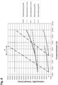
- Fig.6 shows the Fig.5 resulting speed and power parameters at the same working speed range for the drive shaft 2 as in Fig.4 (68%-100%). Due to the fact that the differential drive 5 is only operated in the motor (+) range, the maximum power flow via the differential drive 5 is significantly greater than in the example shown above. At the nominal point, the required power of the differential drive 5 ("servo power") reaches around 500kW, which is 50% of the total drive power (“system power"). This means that the frequency converter 6a, 19 must also be dimensioned accordingly.
- the advantage of this variant is that the transmission ratio of the differential gear 3 is significantly lower than for the variant according to Fig.3 and thus the maximum achievable speed of the differential drive 5 when starting the system is lower.
- Fig.7 shows a further embodiment of a differential system with a gear shift stage.
- the gear pre-stage 16 is expanded by a further gear pre-stage 20, with a different gear ratio than the gear pre-stage 16.
- the switching device 21 one can choose between the two gear pre-stages and thus obtains an adjustable gear 16, 20, 21, which can realize two speed ranges for the drive shaft 2.
- several shift stages can also be implemented.
- Fig.8 shows the Fig.7 resulting speed and power parameters.
- the representation contains two maps - each of them similar to Fig.6 , but with a smaller working speed range for the working machine 1. Due to the two-stage adjustment gear 16, 20, 21, these characteristic maps are offset from each other, which means that with the same overall working speed range for the pump ("pump speed" 68%-100%) a Fig.6 comparable smaller size is required for the differential drive 5.
- the differential drive 5 can be operated in the field weakening range, since the torque required for the differential system is generally smaller than its nominal torque.
- the working speed range in the map with the lower system power is larger than that for the second map.
- the two maps preferably overlap in the hysteresis range "H" in order to avoid frequent switching between the maps.
- the hysteresis range "H” is at the expense of an even smaller differential system in terms of power and, if no overlap of the two maps is required, can also be smaller or even eliminated altogether.
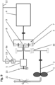
- Fig.9 shows an embodiment of a differential system according to the invention with a reduced speed range.
- the drive train is constructed in the same way as in Fig.5 shown.
- a throttle 22 is integrated in the power system 29 of the working machine 1. This allows the quantity delivered by the working machine 1 to be throttled without reducing the speed of the working machine 1.
- This throttle 22 is usually used in drives that do not have a variable speed in order to regulate/control the quantity delivered.
- the throttle 22 can have a wide variety of designs, with a simple flap being a common variant.
- the variant acc. Fig.9 the additional use of an adaptation gear 10 is possible.
- a clutch 15 and a synchronization brake 14 can be implemented between the second drive or the sun gear 9 and the differential drive 5.
- the gear pre-stage 16 is not absolutely necessary.
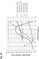
- Fig.10 shows the Fig.9 resulting speed and power parameters.
- the selected operating range of the differential system thus moves into an area with a high operating frequency distribution ("probability").
- probability As soon as the differential drive 5 reaches the base speed (point "T") with decreasing pump speed, it is preferably braked or stopped. A lower delivery rate required for operational reasons is achieved by activating (regulating/controlling) the throttle 22.
- the speeds of the differential system remain essentially constant.
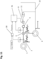
- Fig. 11 a control system for damping drive train vibrations is shown.
- the torque on the differential drive 5 is proportional to the torque in the entire drive train, which makes torque regulation/control or drive train damping possible through the differential drive 5.
- Drive train damping is understood here to mean the targeted regulation of rotary drive train vibrations (working machine, drive shaft 2, differential gear 3, drive machine 4 and differential drive 5), which can occur constantly or transiently and lead to undesirable loads in the entire drive train or in parts. This is achieved by modulating the torque and/or the speed of the differential drive 5 with vibrations of the same frequency.
- Such undesirable drive train vibrations or transient drive train loads can arise either from external loads on the working machine 1, in the drive shaft 2, the differential gear 3 and the differential drive 5 itself or from the drive machine 4 and are typically visible in the speed or torque behavior of the drive train.
- these can be recorded by speed and/or vibration measurements in the drive train or by current measurements on the drive machine 4 and/or on the differential drive 5.
- Direct recording of torques is also possible, but is usually only possible with great effort. The type of recording ultimately always depends on where in the drive train the damping is to take place and whether couplings can be used.
- drive train vibrations are caused, for example, by typical operating behavior on the working machine 1, and their effect on the drive machine 4 is to be compensated, they can be reduced or eliminated by impressing antiphase torque vibrations on the differential drive 5.
- This is the case, for example, with compressors, where one rotation of the piston rod leads to design-specific vibration excitations that correlate strongly with the piston position. Since the respective vibration excitation always occurs at the same piston position, it is sufficient to know the circumferential position or rotational position, e.g. by measurement, in order to be able to compensate for it. Knowing this vibration excitation allows the selective compensation of individual or multiple vibrations at the same time. This is preferably achieved by detecting the position of the piston rod or by one of the methods listed above.
- the necessary synchronous and antiphase torque/speed adjustment is realized by conventional signal processing methods, preferably with oscillators and notch filter algorithms, which simulate the measured vibration excitation with the correct frequencies and evaluate. Integrated into a negative feedback system, the necessary amplitudes and phase positions for the vibrations generated for compensation are automatically set, which are then used to control the actuator on the differential drive 5.
- a constant speed n 4 of the drive machine to be achieved and the speed n 2 of the drive shaft 2 are fed to a comparison circuit 30.
- a control device 31 controls the differential drive 5 on the basis of the desired speed n 5 desired determined therefrom and the actual speed n 5 of the input shaft of the differential drive 5 via the frequency converter 6 in such a way that vibrations of the drive machine 4 are dampened as well as possible or desired.
- the values given with reference to Fig. 11 The drive train damping described can also be used independently of all other embodiments described above.
Landscapes
- Engineering & Computer Science (AREA)
- General Engineering & Computer Science (AREA)
- Mechanical Engineering (AREA)
- Life Sciences & Earth Sciences (AREA)
- Sustainable Development (AREA)
- Sustainable Energy (AREA)
- Chemical & Material Sciences (AREA)
- Combustion & Propulsion (AREA)
- Power Engineering (AREA)
- Physics & Mathematics (AREA)
- General Physics & Mathematics (AREA)
- Automation & Control Theory (AREA)
- Control Of Vehicle Engines Or Engines For Specific Uses (AREA)
- Structure Of Transmissions (AREA)
- Electric Propulsion And Braking For Vehicles (AREA)
- Connection Of Motors, Electrical Generators, Mechanical Devices, And The Like (AREA)
Claims (11)
- Procédé opérationnel d'une chaîne cinématique pourvue d'un arbre d'entraînement (2), d'une machine d'entraînement (4) électrique, apte à fonctionner par moteur et par générateur, connectée sur un réseau électrique (12) et pourvue d'un différentiel (3) doté de trois entraînements ou prises de force, une prise de force étant reliée avec l'arbre d'entraînement (2), un entraînement étant relié avec la machine d'entraînement (4) et un deuxième entraînement étant relié avec un entraînement différentiel (5) électrique apte à fonctionner uniquement par moteur, caractérisé en ce l'entraînement différentiel (5) ne fonctionne que par moteur, alors que la machine d'entraînement (4) fonctionne par moteur ou par générateur et en ce qu'avec l'arbre d'entraînement (2) est reliée une machine de travail (1) qui est une turbine-pompe.
- Procédé selon la revendication 1, caractérisé en ce qu'un premier point de fonctionnement à vitesse constante se situe à un régime de zéro du deuxième entraînement.
- Procédé selon la revendication 2, caractérisé en ce qu'un autre point de fonctionnement à vitesse constante se situe à un régime de la machine d'entraînement (4) auquel celle-ci est connectée au réseau (12), et en ce que le rapport de transmission du différentiel (3) à l'autre point de fonctionnement à vitesse constante est égal à 1.
- Procédé selon l'une quelconque des revendications 1 à 3, caractérisé en ce qu'avec l'arbre d'entraînement (2) est reliée une machine de travail (1) et en ce qu'une partie de la performance de la machine de travail (1) est anéantie par un étranglement (22).
- Procédé selon l'une quelconque des revendications 1 à 4, caractérisé en ce que l'entraînement différentiel (5) peut fonctionner avec une courbe caractéristique à 87 Hz.
- Procédé selon l'une quelconque des revendications 1 à 5, caractérisé en ce que l'entraînement différentiel (5) peut fonctionner dans la plage d'affaiblissement du champ.
- Chaîne cinématique pourvue d'un arbre d'entraînement (2), d'une machine d'entraînement (4) électrique, apte à fonctionner par moteur et par générateur, connectée sur un réseau électrique (12) et pourvue d'un différentiel (3) doté de trois entraînements ou prises de force, une prise de force étant reliée avec l'arbre d'entraînement (2), un entraînement étant relié avec la machine d'entraînement (4) et un deuxième entraînement étant relié avec un entraînement différentiel (5) électrique, caractérisée en ce que l'entraînement différentiel (5) ne fonctionne que par moteur et est connecté sur le réseau électrique (12) par l'intermédiaire d'un redresseur (19) inhérent au réseau, et en ce qu'avec l'arbre d'entraînement (2) est reliée une machine de travail (1) qui est une turbine-pompe.
- Chaîne cinématique selon la revendication 7, caractérisée en ce que l'entraînement différentiel (5) est une machine à courant triphasé.
- Chaîne cinématique selon l'une des revendications 7 ou 8, caractérisée en ce que l'entraînement différentiel (5) est relié par l'intermédiaire d'un étage réducteur d'adaptation (10) avec le deuxième entraînement.
- Chaîne cinématique selon l'une quelconque des revendications 7 à 9, caractérisée en ce qu'entre la machine de travail (1) et le différentiel (3) est placée une transmission variable (16, 20, 21).
- Chaîne cinématique selon l'une quelconque des revendications 7 à 10, caractérisée en ce qu'avec l'arbre d'entraînement (2) est reliée une machine de travail (1) et en ce que la machine de travail (1) est un système de transport dans un système de ligne (29) et en ce que dans le système de ligne (29), un étranglement (22) est placé après la machine de travail (1).
Applications Claiming Priority (2)
| Application Number | Priority Date | Filing Date | Title |
|---|---|---|---|
| ATA418/2013A AT514589B1 (de) | 2013-05-17 | 2013-05-17 | Verfahren zum Betreiben eines Triebstranges und Triebstrang |
| PCT/AT2014/000113 WO2014183142A1 (fr) | 2013-05-17 | 2014-05-19 | Procédé permettant de faire fonctionner une chaîne d'entraînement et de transmission et chaîne d'entraînement et de transmission |
Publications (3)
| Publication Number | Publication Date |
|---|---|
| EP3108154A1 EP3108154A1 (fr) | 2016-12-28 |
| EP3108154B1 EP3108154B1 (fr) | 2021-05-05 |
| EP3108154B2 true EP3108154B2 (fr) | 2024-08-28 |
Family
ID=51032839
Family Applications (1)
| Application Number | Title | Priority Date | Filing Date |
|---|---|---|---|
| EP14733962.6A Active EP3108154B2 (fr) | 2013-05-17 | 2014-05-19 | Procédé permettant de faire fonctionner une chaîne d'entraînement et de transmission et chaîne d'entraînement et de transmission |
Country Status (5)
| Country | Link |
|---|---|
| US (1) | US10378617B2 (fr) |
| EP (1) | EP3108154B2 (fr) |
| CN (1) | CN105209786B (fr) |
| AT (1) | AT514589B1 (fr) |
| WO (1) | WO2014183142A1 (fr) |
Cited By (1)
| Publication number | Priority date | Publication date | Assignee | Title |
|---|---|---|---|---|
| DE102024137092A1 (de) | 2024-12-11 | 2026-06-11 | Voith Patent Gmbh | Überlastantrieb für Pumpen |
Families Citing this family (18)
| Publication number | Priority date | Publication date | Assignee | Title |
|---|---|---|---|---|
| US10106255B2 (en) * | 2014-05-14 | 2018-10-23 | Bell Helicopter Textron Inc. | Rotary pylon conversion actuator for tiltrotor aircraft |
| US10454394B2 (en) * | 2014-07-18 | 2019-10-22 | Mitsubishi Heavy Industries Compressor Corporation | Rotational driving force imparting device and electric motor device for the same |
| AT516038B1 (de) * | 2014-12-12 | 2016-02-15 | Set Sustainable Energy Technologies Gmbh | Antriebsstrang |
| AT14813U1 (de) | 2014-12-22 | 2016-06-15 | Gerald Hehenberger | Antriebsstrang und Verfahren zum Betreiben eines Antriebsstranges |
| AT517170B1 (de) * | 2015-04-27 | 2019-07-15 | Set Sustainable Energy Tech Gmbh | Verfahren zum Anfahren eines Triebstranges |
| DE102015107934A1 (de) * | 2015-05-20 | 2016-11-24 | Voith Patent Gmbh | Drehzahländerbares Antriebssystem und Verfahren zum Aufstarten und/oder Betreiben eines Drehzahländerbaren Antriebssystems |
| DE102016200112A1 (de) * | 2016-01-07 | 2017-07-13 | Leybold Gmbh | Vakuumpumpenantrieb mit Stern-Dreieck-Umschaltung |
| CN107355347A (zh) * | 2016-05-10 | 2017-11-17 | 张占海 | 蓄能式风力发电机 |
| WO2018029804A1 (fr) | 2016-08-10 | 2018-02-15 | 三菱重工コンプレッサ株式会社 | Multiplicateur de vitesse variable |
| US10054204B2 (en) * | 2017-01-09 | 2018-08-21 | Richard Harper | Variable output planetary gear set with electromagnetic braking |
| AT15940U1 (de) * | 2017-03-23 | 2018-10-15 | Ing Gerald Hehenberger Dipl | Verfahren zum Betreiben eines Triebstranges und Triebstrang |
| AT519747B1 (de) * | 2017-05-23 | 2018-10-15 | Ing Gerald Hehenberger Dipl | Verfahren und Vorrichtung zum Regeln des Betriebes eines Triebstranges |
| JP7014638B2 (ja) | 2018-02-27 | 2022-02-01 | 三菱重工コンプレッサ株式会社 | 可変速増速機及び可変速増速機の制御方法 |
| GB2605939B (en) * | 2021-02-04 | 2025-01-15 | Natures Natural Power Ltd | Improvements in and relating to wind turbines |
| CN114233816A (zh) * | 2021-11-12 | 2022-03-25 | 北京航空航天大学 | 一种基于行星轮系的机械运动整流器 |
| CN114233824A (zh) * | 2022-01-07 | 2022-03-25 | 黄志扬 | 一种全范围调速的机电一体化行星调速装置 |
| DE102022107537A1 (de) * | 2022-03-30 | 2023-10-05 | Technische Universität Ilmenau, Körperschaft des öffentlichen Rechts | Stromaggregat und Verfahren zur Erzeugung von elektrischem Strom mit konstanter Netzfrequenz |
| JP7878083B2 (ja) * | 2023-02-03 | 2026-06-23 | トヨタ自動車株式会社 | 発電装置 |
Citations (3)
| Publication number | Priority date | Publication date | Assignee | Title |
|---|---|---|---|---|
| DE1138720B (de) † | 1958-04-01 | 1962-10-25 | Siemens Ag | Getriebe zwischen einer Pumpenturbine und einer elektrischen Maschine |
| US4514991A (en) † | 1983-10-17 | 1985-05-07 | Carrier Corporation | Variable speed drive motor system with inverter control |
| US7211018B2 (en) † | 2002-02-21 | 2007-05-01 | Ebara Corporation | Differential planetary gear device, and differential planetary gear device starting device and starting method |
Family Cites Families (24)
| Publication number | Priority date | Publication date | Assignee | Title |
|---|---|---|---|---|
| DD61720A (fr) | ||||
| US2346979A (en) * | 1940-08-13 | 1944-04-18 | Daniel G Lilley | Variable pitch propeller |
| US2806191A (en) * | 1948-11-02 | 1957-09-10 | Pollopas Patents Ltd | Electric motor driving arrangement |
| DE1098600B (de) | 1955-06-30 | 1961-02-02 | Nat Res Dev | Dreiphasiger polumschaltbarer Induktionsmotor |
| DE1077982B (de) | 1957-04-06 | 1960-03-17 | Siemens Ag | Kreiselpumpe mit hydraulischer Entlastungsvorrichtung |
| GB2225616A (en) | 1988-11-30 | 1990-06-06 | Wind Energy Group Limited | Power generating system including gearing allowing constant generator torque |
| US5971880A (en) * | 1998-08-07 | 1999-10-26 | Keiser; Fred | Infinitely variable ratio transmission |
| US7115066B1 (en) * | 2002-02-11 | 2006-10-03 | Lee Paul Z | Continuously variable ratio transmission |
| GR20050100141A (el) * | 2005-03-21 | 2006-11-01 | Γεωργιου Νικολαος Μποτσης | Υγρομηχανικα αυτοπροσαρμοζομενα συστηματα μεταφορας ισχυος δια γραμμικης αναδρασης με μετρητες ροπης φορτιου πραγματικου χρονου (c.v.t.) |
| EP2924262A1 (fr) * | 2006-06-26 | 2015-09-30 | Fallbrook Intellectual Property Company LLC | Transmission variable en continu |
| EP1936205A1 (fr) | 2006-12-22 | 2008-06-25 | Grundfos Management A/S | Procédé destiné au fonctionnement d'un agrégat de pompe centrifuge à vitesse de rotation réglable |
| FR2927394B1 (fr) * | 2008-02-11 | 2010-06-04 | Roucar Gear Technologies Bv | Dispositif de transmission pour machine de production d'electricite a partir d'une source motrice a vitesse variable, unite de production electrique et eolienne ainsi equipees, et procede de reglage d'un rapport de transmission |
| CN101265961A (zh) | 2008-04-16 | 2008-09-17 | 大连橡胶塑料机械股份有限公司 | 大型挤压造粒机组主减速器的无级变速机构 |
| AT507394B1 (de) | 2008-10-09 | 2012-06-15 | Gerald Dipl Ing Hehenberger | Windkraftanlage |
| NO332673B1 (no) * | 2008-11-24 | 2012-12-03 | Aker Engineering & Technology | Frekvensomformer |
| US8008797B2 (en) * | 2009-02-13 | 2011-08-30 | Bernard Joseph Simon | System for converting wind power to electrcial power with transmission |
| JP2012519809A (ja) * | 2009-03-06 | 2012-08-30 | ディーティーアイ グループ ビー.ブイ. | 電気またはハイブリッド駆動装置用トランスミッション |
| AT508411B1 (de) * | 2009-07-02 | 2011-06-15 | Hehenberger Gerald Dipl Ing | Differenzialgetriebe für energiegewinnungsanlage und verfahren zum betreiben |
| DK2402597T3 (en) * | 2010-06-29 | 2016-11-28 | Siemens Ag | The wind turbine yaw system and method for controlling thereof |
| DE102010037780A1 (de) * | 2010-09-27 | 2012-03-29 | Claas Selbstfahrende Erntemaschinen Gmbh | Motorsteuerunskonzept und Vorrichtung zum Steuern der Leistung eines Motorfahrzeuges |
| CN102859186A (zh) * | 2011-04-14 | 2013-01-02 | 三菱重工业株式会社 | 风力发电设备的输出正常化方法及风力发电设备的输出正常化装置 |
| AT511782A1 (de) | 2011-08-11 | 2013-02-15 | Hehenberger Gerald | Energiegewinnungsanlage, insbesondere windkraftanlage |
| DE102011087109B3 (de) * | 2011-11-25 | 2013-04-04 | Zollern Gmbh & Co. Kg | Vorrichtung und Verfahren zur Gewinnung von Energie aus einer Fluidströmung |
| DE202012101708U1 (de) | 2012-05-10 | 2012-06-13 | Gerald Hehenberger | Differenzialgetriebe für Energiegewinnungsanlage |
-
2013
- 2013-05-17 AT ATA418/2013A patent/AT514589B1/de active
- 2013-12-30 CN CN201380076675.8A patent/CN105209786B/zh active Active
-
2014
- 2014-05-19 WO PCT/AT2014/000113 patent/WO2014183142A1/fr not_active Ceased
- 2014-05-19 EP EP14733962.6A patent/EP3108154B2/fr active Active
- 2014-05-19 US US14/785,802 patent/US10378617B2/en active Active
Patent Citations (3)
| Publication number | Priority date | Publication date | Assignee | Title |
|---|---|---|---|---|
| DE1138720B (de) † | 1958-04-01 | 1962-10-25 | Siemens Ag | Getriebe zwischen einer Pumpenturbine und einer elektrischen Maschine |
| US4514991A (en) † | 1983-10-17 | 1985-05-07 | Carrier Corporation | Variable speed drive motor system with inverter control |
| US7211018B2 (en) † | 2002-02-21 | 2007-05-01 | Ebara Corporation | Differential planetary gear device, and differential planetary gear device starting device and starting method |
Cited By (1)
| Publication number | Priority date | Publication date | Assignee | Title |
|---|---|---|---|---|
| DE102024137092A1 (de) | 2024-12-11 | 2026-06-11 | Voith Patent Gmbh | Überlastantrieb für Pumpen |
Also Published As
| Publication number | Publication date |
|---|---|
| EP3108154B1 (fr) | 2021-05-05 |
| CN105209786A (zh) | 2015-12-30 |
| EP3108154A1 (fr) | 2016-12-28 |
| CN105209786B (zh) | 2019-04-02 |
| US10378617B2 (en) | 2019-08-13 |
| WO2014183142A1 (fr) | 2014-11-20 |
| AT514589A4 (de) | 2015-02-15 |
| AT514589B1 (de) | 2015-02-15 |
| US20160076630A1 (en) | 2016-03-17 |
Similar Documents
| Publication | Publication Date | Title |
|---|---|---|
| EP3108154B1 (fr) | Procédé permettant de faire fonctionner une chaîne d'entraînement et de transmission et chaîne d'entraînement et de transmission | |
| EP2997284B2 (fr) | Procédé permettant de faire fonctionner une chaîne cinématique et chaîne cinématique | |
| EP2997285B1 (fr) | Procédé et dispositif permettant de mettre en marche une chaîne d'entraînement et de transmission | |
| AT517170B1 (de) | Verfahren zum Anfahren eines Triebstranges | |
| AT516038B1 (de) | Antriebsstrang | |
| EP3298685B2 (fr) | Système d'entraînement à vitesse de rotation variable et procédé de démarrage et/ou de fonctionnement d'un système d'entraînement à vitesse de rotation variable | |
| EP2990610B1 (fr) | Moteur d'avion et procede de fonctionnement d'un moteur d'avion | |
| WO2016091958A1 (fr) | Procédé permettant de faire fonctionner un groupe d'entraînement | |
| AT508411A1 (de) | Differenzialgetriebe für energiegewinnungsanlage und verfahren zum betreiben | |
| DE102014210868A1 (de) | Vorrichtung zur Leistungsübertragung und Maschinenanordnung damit | |
| EP2986846B1 (fr) | Mécanisme d'entraînement et procédé servant à faire fonctionner un mécanisme d'entraînement de ce type | |
| EP3238337B1 (fr) | Procédé de fonctionnement de transmission | |
| DE102014210869A1 (de) | Vorrichtung zur insbesondere Leistungsübertragung | |
| WO2019122224A1 (fr) | Système électromécanique ainsi que réducteur différentiel pour la transmission d'une énergie de rotation | |
| DE202015104656U1 (de) | Antriebsstrang einer Energiegewinnungsanlage | |
| AT516180B1 (de) | Verfahren zum Anfahren eines Triebstranges und Antrieb hierfür | |
| AT523332B1 (de) | Verfahren zum Verbinden einer elektrischen Asynchronmaschine eines Triebstranges mit einem elektrischen Netz | |
| AT15940U1 (de) | Verfahren zum Betreiben eines Triebstranges und Triebstrang | |
| AT14302U1 (de) | Verfahren zum Betreiben eines Triebstranges und Triebstrang | |
| AT15388U1 (de) | Triebstrang und Verfahren zum Betreiben eines Triebstranges |
Legal Events
| Date | Code | Title | Description |
|---|---|---|---|
| PUAI | Public reference made under article 153(3) epc to a published international application that has entered the european phase |
Free format text: ORIGINAL CODE: 0009012 |
|
| STAA | Information on the status of an ep patent application or granted ep patent |
Free format text: STATUS: REQUEST FOR EXAMINATION WAS MADE |
|
| 17P | Request for examination filed |
Effective date: 20151216 |
|
| AK | Designated contracting states |
Kind code of ref document: A1 Designated state(s): AL AT BE BG CH CY CZ DE DK EE ES FI FR GB GR HR HU IE IS IT LI LT LU LV MC MK MT NL NO PL PT RO RS SE SI SK SM TR |
|
| AX | Request for extension of the european patent |
Extension state: BA ME |
|
| STAA | Information on the status of an ep patent application or granted ep patent |
Free format text: STATUS: EXAMINATION IS IN PROGRESS |
|
| 17Q | First examination report despatched |
Effective date: 20200127 |
|
| GRAP | Despatch of communication of intention to grant a patent |
Free format text: ORIGINAL CODE: EPIDOSNIGR1 |
|
| STAA | Information on the status of an ep patent application or granted ep patent |
Free format text: STATUS: GRANT OF PATENT IS INTENDED |
|
| RIC1 | Information provided on ipc code assigned before grant |
Ipc: F03D 7/02 20060101ALI20201105BHEP Ipc: F03D 15/00 20160101ALI20201105BHEP Ipc: F16H 3/72 20060101AFI20201105BHEP |
|
| INTG | Intention to grant announced |
Effective date: 20201124 |
|
| GRAS | Grant fee paid |
Free format text: ORIGINAL CODE: EPIDOSNIGR3 |
|
| GRAA | (expected) grant |
Free format text: ORIGINAL CODE: 0009210 |
|
| STAA | Information on the status of an ep patent application or granted ep patent |
Free format text: STATUS: THE PATENT HAS BEEN GRANTED |
|
| AK | Designated contracting states |
Kind code of ref document: B1 Designated state(s): AL AT BE BG CH CY CZ DE DK EE ES FI FR GB GR HR HU IE IS IT LI LT LU LV MC MK MT NL NO PL PT RO RS SE SI SK SM TR |
|
| DAX | Request for extension of the european patent (deleted) | ||
| REG | Reference to a national code |
Ref country code: GB Ref legal event code: FG4D Free format text: NOT ENGLISH |
|
| REG | Reference to a national code |
Ref country code: CH Ref legal event code: EP |
|
| REG | Reference to a national code |
Ref country code: AT Ref legal event code: REF Ref document number: 1390196 Country of ref document: AT Kind code of ref document: T Effective date: 20210515 |
|
| REG | Reference to a national code |
Ref country code: IE Ref legal event code: FG4D Free format text: LANGUAGE OF EP DOCUMENT: GERMAN |
|
| REG | Reference to a national code |
Ref country code: DE Ref legal event code: R096 Ref document number: 502014015552 Country of ref document: DE |
|
| REG | Reference to a national code |
Ref country code: LT Ref legal event code: MG9D |
|
| PG25 | Lapsed in a contracting state [announced via postgrant information from national office to epo] |
Ref country code: LT Free format text: LAPSE BECAUSE OF FAILURE TO SUBMIT A TRANSLATION OF THE DESCRIPTION OR TO PAY THE FEE WITHIN THE PRESCRIBED TIME-LIMIT Effective date: 20210505 Ref country code: FI Free format text: LAPSE BECAUSE OF FAILURE TO SUBMIT A TRANSLATION OF THE DESCRIPTION OR TO PAY THE FEE WITHIN THE PRESCRIBED TIME-LIMIT Effective date: 20210505 Ref country code: BG Free format text: LAPSE BECAUSE OF FAILURE TO SUBMIT A TRANSLATION OF THE DESCRIPTION OR TO PAY THE FEE WITHIN THE PRESCRIBED TIME-LIMIT Effective date: 20210805 Ref country code: HR Free format text: LAPSE BECAUSE OF FAILURE TO SUBMIT A TRANSLATION OF THE DESCRIPTION OR TO PAY THE FEE WITHIN THE PRESCRIBED TIME-LIMIT Effective date: 20210505 |
|
| PG25 | Lapsed in a contracting state [announced via postgrant information from national office to epo] |
Ref country code: PL Free format text: LAPSE BECAUSE OF FAILURE TO SUBMIT A TRANSLATION OF THE DESCRIPTION OR TO PAY THE FEE WITHIN THE PRESCRIBED TIME-LIMIT Effective date: 20210505 Ref country code: NO Free format text: LAPSE BECAUSE OF FAILURE TO SUBMIT A TRANSLATION OF THE DESCRIPTION OR TO PAY THE FEE WITHIN THE PRESCRIBED TIME-LIMIT Effective date: 20210805 Ref country code: PT Free format text: LAPSE BECAUSE OF FAILURE TO SUBMIT A TRANSLATION OF THE DESCRIPTION OR TO PAY THE FEE WITHIN THE PRESCRIBED TIME-LIMIT Effective date: 20210906 Ref country code: ES Free format text: LAPSE BECAUSE OF FAILURE TO SUBMIT A TRANSLATION OF THE DESCRIPTION OR TO PAY THE FEE WITHIN THE PRESCRIBED TIME-LIMIT Effective date: 20210505 Ref country code: SE Free format text: LAPSE BECAUSE OF FAILURE TO SUBMIT A TRANSLATION OF THE DESCRIPTION OR TO PAY THE FEE WITHIN THE PRESCRIBED TIME-LIMIT Effective date: 20210505 Ref country code: RS Free format text: LAPSE BECAUSE OF FAILURE TO SUBMIT A TRANSLATION OF THE DESCRIPTION OR TO PAY THE FEE WITHIN THE PRESCRIBED TIME-LIMIT Effective date: 20210505 Ref country code: GR Free format text: LAPSE BECAUSE OF FAILURE TO SUBMIT A TRANSLATION OF THE DESCRIPTION OR TO PAY THE FEE WITHIN THE PRESCRIBED TIME-LIMIT Effective date: 20210806 Ref country code: LV Free format text: LAPSE BECAUSE OF FAILURE TO SUBMIT A TRANSLATION OF THE DESCRIPTION OR TO PAY THE FEE WITHIN THE PRESCRIBED TIME-LIMIT Effective date: 20210505 Ref country code: IS Free format text: LAPSE BECAUSE OF FAILURE TO SUBMIT A TRANSLATION OF THE DESCRIPTION OR TO PAY THE FEE WITHIN THE PRESCRIBED TIME-LIMIT Effective date: 20210905 |
|
| REG | Reference to a national code |
Ref country code: NL Ref legal event code: MP Effective date: 20210505 |
|
| REG | Reference to a national code |
Ref country code: CH Ref legal event code: PL |
|
| PG25 | Lapsed in a contracting state [announced via postgrant information from national office to epo] |
Ref country code: NL Free format text: LAPSE BECAUSE OF FAILURE TO SUBMIT A TRANSLATION OF THE DESCRIPTION OR TO PAY THE FEE WITHIN THE PRESCRIBED TIME-LIMIT Effective date: 20210505 |
|
| PG25 | Lapsed in a contracting state [announced via postgrant information from national office to epo] |
Ref country code: RO Free format text: LAPSE BECAUSE OF FAILURE TO SUBMIT A TRANSLATION OF THE DESCRIPTION OR TO PAY THE FEE WITHIN THE PRESCRIBED TIME-LIMIT Effective date: 20210505 Ref country code: CH Free format text: LAPSE BECAUSE OF NON-PAYMENT OF DUE FEES Effective date: 20210531 Ref country code: LI Free format text: LAPSE BECAUSE OF NON-PAYMENT OF DUE FEES Effective date: 20210531 Ref country code: LU Free format text: LAPSE BECAUSE OF NON-PAYMENT OF DUE FEES Effective date: 20210519 Ref country code: SM Free format text: LAPSE BECAUSE OF FAILURE TO SUBMIT A TRANSLATION OF THE DESCRIPTION OR TO PAY THE FEE WITHIN THE PRESCRIBED TIME-LIMIT Effective date: 20210505 Ref country code: SK Free format text: LAPSE BECAUSE OF FAILURE TO SUBMIT A TRANSLATION OF THE DESCRIPTION OR TO PAY THE FEE WITHIN THE PRESCRIBED TIME-LIMIT Effective date: 20210505 Ref country code: EE Free format text: LAPSE BECAUSE OF FAILURE TO SUBMIT A TRANSLATION OF THE DESCRIPTION OR TO PAY THE FEE WITHIN THE PRESCRIBED TIME-LIMIT Effective date: 20210505 Ref country code: CZ Free format text: LAPSE BECAUSE OF FAILURE TO SUBMIT A TRANSLATION OF THE DESCRIPTION OR TO PAY THE FEE WITHIN THE PRESCRIBED TIME-LIMIT Effective date: 20210505 Ref country code: DK Free format text: LAPSE BECAUSE OF FAILURE TO SUBMIT A TRANSLATION OF THE DESCRIPTION OR TO PAY THE FEE WITHIN THE PRESCRIBED TIME-LIMIT Effective date: 20210505 |
|
| REG | Reference to a national code |
Ref country code: DE Ref legal event code: R026 Ref document number: 502014015552 Country of ref document: DE |
|
| PLBI | Opposition filed |
Free format text: ORIGINAL CODE: 0009260 |
|
| REG | Reference to a national code |
Ref country code: BE Ref legal event code: MM Effective date: 20210531 |
|
| PLAX | Notice of opposition and request to file observation + time limit sent |
Free format text: ORIGINAL CODE: EPIDOSNOBS2 |
|
| 26 | Opposition filed |
Opponent name: VOITH PATENT GMBH Effective date: 20220202 |
|
| PG25 | Lapsed in a contracting state [announced via postgrant information from national office to epo] |
Ref country code: MC Free format text: LAPSE BECAUSE OF FAILURE TO SUBMIT A TRANSLATION OF THE DESCRIPTION OR TO PAY THE FEE WITHIN THE PRESCRIBED TIME-LIMIT Effective date: 20210505 |
|
| GBPC | Gb: european patent ceased through non-payment of renewal fee |
Effective date: 20210805 |
|
| PG25 | Lapsed in a contracting state [announced via postgrant information from national office to epo] |
Ref country code: IE Free format text: LAPSE BECAUSE OF NON-PAYMENT OF DUE FEES Effective date: 20210519 |
|
| PG25 | Lapsed in a contracting state [announced via postgrant information from national office to epo] |
Ref country code: IS Free format text: LAPSE BECAUSE OF FAILURE TO SUBMIT A TRANSLATION OF THE DESCRIPTION OR TO PAY THE FEE WITHIN THE PRESCRIBED TIME-LIMIT Effective date: 20210905 Ref country code: FR Free format text: LAPSE BECAUSE OF NON-PAYMENT OF DUE FEES Effective date: 20210705 Ref country code: AL Free format text: LAPSE BECAUSE OF FAILURE TO SUBMIT A TRANSLATION OF THE DESCRIPTION OR TO PAY THE FEE WITHIN THE PRESCRIBED TIME-LIMIT Effective date: 20210505 |
|
| PLBB | Reply of patent proprietor to notice(s) of opposition received |
Free format text: ORIGINAL CODE: EPIDOSNOBS3 |
|
| REG | Reference to a national code |
Ref country code: AT Ref legal event code: MM01 Ref document number: 1390196 Country of ref document: AT Kind code of ref document: T Effective date: 20210519 |
|
| PG25 | Lapsed in a contracting state [announced via postgrant information from national office to epo] |
Ref country code: IT Free format text: LAPSE BECAUSE OF FAILURE TO SUBMIT A TRANSLATION OF THE DESCRIPTION OR TO PAY THE FEE WITHIN THE PRESCRIBED TIME-LIMIT Effective date: 20210505 Ref country code: GB Free format text: LAPSE BECAUSE OF NON-PAYMENT OF DUE FEES Effective date: 20210805 Ref country code: BE Free format text: LAPSE BECAUSE OF NON-PAYMENT OF DUE FEES Effective date: 20210531 |
|
| PG25 | Lapsed in a contracting state [announced via postgrant information from national office to epo] |
Ref country code: AT Free format text: LAPSE BECAUSE OF NON-PAYMENT OF DUE FEES Effective date: 20210519 |
|
| PG25 | Lapsed in a contracting state [announced via postgrant information from national office to epo] |
Ref country code: HU Free format text: LAPSE BECAUSE OF FAILURE TO SUBMIT A TRANSLATION OF THE DESCRIPTION OR TO PAY THE FEE WITHIN THE PRESCRIBED TIME-LIMIT; INVALID AB INITIO Effective date: 20140519 |
|
| P01 | Opt-out of the competence of the unified patent court (upc) registered |
Effective date: 20230517 |
|
| PG25 | Lapsed in a contracting state [announced via postgrant information from national office to epo] |
Ref country code: CY Free format text: LAPSE BECAUSE OF FAILURE TO SUBMIT A TRANSLATION OF THE DESCRIPTION OR TO PAY THE FEE WITHIN THE PRESCRIBED TIME-LIMIT Effective date: 20210505 |
|
| REG | Reference to a national code |
Ref country code: DE Ref legal event code: R081 Ref document number: 502014015552 Country of ref document: DE Owner name: SET SUSTAINABLE ENERGY TECHNOLOGIES GMBH, AT Free format text: FORMER OWNER: HEHENBERGER, GERALD, KLAGENFURT, AT |
|
| PLBP | Opposition withdrawn |
Free format text: ORIGINAL CODE: 0009264 |
|
| PG25 | Lapsed in a contracting state [announced via postgrant information from national office to epo] |
Ref country code: MK Free format text: LAPSE BECAUSE OF FAILURE TO SUBMIT A TRANSLATION OF THE DESCRIPTION OR TO PAY THE FEE WITHIN THE PRESCRIBED TIME-LIMIT Effective date: 20210505 |
|
| PUAH | Patent maintained in amended form |
Free format text: ORIGINAL CODE: 0009272 |
|
| STAA | Information on the status of an ep patent application or granted ep patent |
Free format text: STATUS: PATENT MAINTAINED AS AMENDED |
|
| 27A | Patent maintained in amended form |
Effective date: 20240828 |
|
| AK | Designated contracting states |
Kind code of ref document: B2 Designated state(s): AL AT BE BG CH CY CZ DE DK EE ES FI FR GB GR HR HU IE IS IT LI LT LU LV MC MK MT NL NO PL PT RO RS SE SI SK SM TR |
|
| REG | Reference to a national code |
Ref country code: DE Ref legal event code: R102 Ref document number: 502014015552 Country of ref document: DE |
|
| PG25 | Lapsed in a contracting state [announced via postgrant information from national office to epo] |
Ref country code: MT Free format text: LAPSE BECAUSE OF FAILURE TO SUBMIT A TRANSLATION OF THE DESCRIPTION OR TO PAY THE FEE WITHIN THE PRESCRIBED TIME-LIMIT Effective date: 20210505 |
|
| PG25 | Lapsed in a contracting state [announced via postgrant information from national office to epo] |
Ref country code: TR Free format text: LAPSE BECAUSE OF FAILURE TO SUBMIT A TRANSLATION OF THE DESCRIPTION OR TO PAY THE FEE WITHIN THE PRESCRIBED TIME-LIMIT Effective date: 20210505 |
|
| REG | Reference to a national code |
Ref country code: DE Ref legal event code: R082 Ref document number: 502014015552 Country of ref document: DE Representative=s name: SCHNEIDERS & BEHRENDT PARTMBB, RECHTS- UND PAT, DE |
|
| PGFP | Annual fee paid to national office [announced via postgrant information from national office to epo] |
Ref country code: DE Payment date: 20260522 Year of fee payment: 13 |