EP3108290B1 - Appareil et procédé pour mise en forme de faisceau de sortie laser à fibres pour combinaison spectrale de faisceaux - Google Patents
Appareil et procédé pour mise en forme de faisceau de sortie laser à fibres pour combinaison spectrale de faisceaux Download PDFInfo
- Publication number
- EP3108290B1 EP3108290B1 EP15792001.8A EP15792001A EP3108290B1 EP 3108290 B1 EP3108290 B1 EP 3108290B1 EP 15792001 A EP15792001 A EP 15792001A EP 3108290 B1 EP3108290 B1 EP 3108290B1
- Authority
- EP
- European Patent Office
- Prior art keywords
- annular
- laser
- beams
- fiber
- output
- Prior art date
- Legal status (The legal status is an assumption and is not a legal conclusion. Google has not performed a legal analysis and makes no representation as to the accuracy of the status listed.)
- Not-in-force
Links
Images






Classifications
-
- G—PHYSICS
- G02—OPTICS
- G02B—OPTICAL ELEMENTS, SYSTEMS OR APPARATUS
- G02B27/00—Optical systems or apparatus not provided for by any of the groups G02B1/00 - G02B26/00, G02B30/00
- G02B27/09—Beam shaping, e.g. changing the cross-sectional area, not otherwise provided for
- G02B27/0927—Systems for changing the beam intensity distribution, e.g. Gaussian to top-hat
-
- G—PHYSICS
- G02—OPTICS
- G02B—OPTICAL ELEMENTS, SYSTEMS OR APPARATUS
- G02B19/00—Condensers, e.g. light collectors or similar non-imaging optics
- G02B19/0004—Condensers, e.g. light collectors or similar non-imaging optics characterised by the optical means employed
- G02B19/0019—Condensers, e.g. light collectors or similar non-imaging optics characterised by the optical means employed having reflective surfaces only (e.g. louvre systems, systems with multiple planar reflectors)
- G02B19/0023—Condensers, e.g. light collectors or similar non-imaging optics characterised by the optical means employed having reflective surfaces only (e.g. louvre systems, systems with multiple planar reflectors) at least one surface having optical power
-
- G—PHYSICS
- G02—OPTICS
- G02B—OPTICAL ELEMENTS, SYSTEMS OR APPARATUS
- G02B19/00—Condensers, e.g. light collectors or similar non-imaging optics
- G02B19/0033—Condensers, e.g. light collectors or similar non-imaging optics characterised by the use
- G02B19/0047—Condensers, e.g. light collectors or similar non-imaging optics characterised by the use for use with a light source
-
- G—PHYSICS
- G02—OPTICS
- G02B—OPTICAL ELEMENTS, SYSTEMS OR APPARATUS
- G02B27/00—Optical systems or apparatus not provided for by any of the groups G02B1/00 - G02B26/00, G02B30/00
- G02B27/09—Beam shaping, e.g. changing the cross-sectional area, not otherwise provided for
- G02B27/0905—Dividing and/or superposing multiple light beams
-
- G—PHYSICS
- G02—OPTICS
- G02B—OPTICAL ELEMENTS, SYSTEMS OR APPARATUS
- G02B27/00—Optical systems or apparatus not provided for by any of the groups G02B1/00 - G02B26/00, G02B30/00
- G02B27/09—Beam shaping, e.g. changing the cross-sectional area, not otherwise provided for
- G02B27/0938—Using specific optical elements
- G02B27/0944—Diffractive optical elements, e.g. gratings, holograms
-
- G—PHYSICS
- G02—OPTICS
- G02B—OPTICAL ELEMENTS, SYSTEMS OR APPARATUS
- G02B27/00—Optical systems or apparatus not provided for by any of the groups G02B1/00 - G02B26/00, G02B30/00
- G02B27/10—Beam splitting or combining systems
- G02B27/1006—Beam splitting or combining systems for splitting or combining different wavelengths
-
- G—PHYSICS
- G02—OPTICS
- G02B—OPTICAL ELEMENTS, SYSTEMS OR APPARATUS
- G02B27/00—Optical systems or apparatus not provided for by any of the groups G02B1/00 - G02B26/00, G02B30/00
- G02B27/10—Beam splitting or combining systems
- G02B27/1086—Beam splitting or combining systems operating by diffraction only
-
- G—PHYSICS
- G02—OPTICS
- G02B—OPTICAL ELEMENTS, SYSTEMS OR APPARATUS
- G02B27/00—Optical systems or apparatus not provided for by any of the groups G02B1/00 - G02B26/00, G02B30/00
- G02B27/30—Collimators
-
- G—PHYSICS
- G02—OPTICS
- G02B—OPTICAL ELEMENTS, SYSTEMS OR APPARATUS
- G02B5/00—Optical elements other than lenses
- G02B5/001—Axicons, waxicons, reflaxicons
-
- H—ELECTRICITY
- H01—ELECTRIC ELEMENTS
- H01S—DEVICES USING THE PROCESS OF LIGHT AMPLIFICATION BY STIMULATED EMISSION OF RADIATION [LASER] TO AMPLIFY OR GENERATE LIGHT; DEVICES USING STIMULATED EMISSION OF ELECTROMAGNETIC RADIATION IN WAVE RANGES OTHER THAN OPTICAL
- H01S3/00—Lasers, i.e. devices using stimulated emission of electromagnetic radiation in the infrared, visible or ultraviolet wave range
- H01S3/005—Optical devices external to the laser cavity, specially adapted for lasers, e.g. for homogenisation of the beam or for manipulating laser pulses, e.g. pulse shaping
-
- H—ELECTRICITY
- H01—ELECTRIC ELEMENTS
- H01S—DEVICES USING THE PROCESS OF LIGHT AMPLIFICATION BY STIMULATED EMISSION OF RADIATION [LASER] TO AMPLIFY OR GENERATE LIGHT; DEVICES USING STIMULATED EMISSION OF ELECTROMAGNETIC RADIATION IN WAVE RANGES OTHER THAN OPTICAL
- H01S3/00—Lasers, i.e. devices using stimulated emission of electromagnetic radiation in the infrared, visible or ultraviolet wave range
- H01S3/05—Construction or shape of optical resonators; Accommodation of active medium therein; Shape of active medium
- H01S3/06—Construction or shape of active medium
- H01S3/063—Waveguide lasers, i.e. whereby the dimensions of the waveguide are of the order of the light wavelength
- H01S3/067—Fibre lasers
-
- H—ELECTRICITY
- H01—ELECTRIC ELEMENTS
- H01S—DEVICES USING THE PROCESS OF LIGHT AMPLIFICATION BY STIMULATED EMISSION OF RADIATION [LASER] TO AMPLIFY OR GENERATE LIGHT; DEVICES USING STIMULATED EMISSION OF ELECTROMAGNETIC RADIATION IN WAVE RANGES OTHER THAN OPTICAL
- H01S3/00—Lasers, i.e. devices using stimulated emission of electromagnetic radiation in the infrared, visible or ultraviolet wave range
- H01S3/23—Arrangements of two or more lasers not provided for in groups H01S3/02 - H01S3/22, e.g. tandem arrangements of separate active media
- H01S3/2383—Parallel arrangements
- H01S3/2391—Parallel arrangements emitting at different wavelengths
Definitions
- the first surface of the fiber-array plate includes indicia configured to assist in the alignment of the plurality of optical fibers on the first surface of the fiber-array plate.
- the second surface of the fiber-array plate includes a plurality of beam-shaping optics configured to shape the composite output beam.
- Some embodiments further include a bandpass filter to remove signal other than the desired signal wavelength and/or a time gate to remove signal at times other than during the desired signal pulse.
- Some embodiments include photonic-crystal structures to define the core for the signal and/or the inner cladding for the pump.
- Some embodiments include an inner glass cladding to confine the signal in the core and an outer glass cladding to confine pump light in the inner cladding.
- Patent 8,179,594 to Tidwell, et al. issued May 15, 2012 titled "Method and apparatus for spectral-beam combining of fanned-in laser beams with chromatic-dispersion compensation using a plurality of diffractive gratings," is assigned to the owner of the present application.
- Patent 7,846,767 to Sung issued December 7, 2010 titled “Semiconductor-on-diamond devices and associated methods.”
- Patent 7,846,767 describes semiconductor-on-diamond (SOD) substrates and methods for making such substrates.
- a method of making an SOD device includes etching depressions into an etch surface of a semiconductor substrate to a uniform depth, depositing a diamond layer onto the etch surface to form diamond-filled depressions, and thinning the semiconductor substrate at a thinning surface opposite the etch surface until the diamond filled depressions are exposed, thus forming a semiconductor device having a thickness substantially equal to the uniform depth.
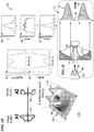
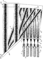
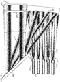
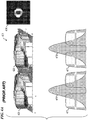
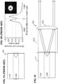
- a plurality of fibers are fused to a single focussing and annular-beam shaping assembly that forms annular beams that are then collimated and directed towards a spectral-beam-combining grating, which combines the annular beams impinging on the grating into a single annular beam.
- the single spectrally combined annular beam is output through a Cassegrain optical projector, and in some embodiments, the beam is used for military purposes such as disabling aircraft, naval vessels, or other mobile vehicles.
- Some embodiments of the apparatus further include a materials-processing system; an electrical power supply connected to the materials-processing system; a laser controller in the materials-processing system and operatively coupled to receive electrical power from the electrical power supply and operably coupled to power and control the plurality of laser sources; and a Cassegrain projector mounted to the materials-processing system and operatively coupled to receive the first annular spectrally combined beam and configured to form a collimated second annular output beam from the optical energy of the first annular spectrally combined beam; wherein the Cassegrain projector is operable to direct the second annular output beam toward materials being processed all at once.
- SBC spectral beam combining
- mirror 173 is substantially identical to mirror 170, while in other embodiments, mirror 173 has a relatively thin shell and is air-cooled on front and back, or has a hollow core 175 (as shown in Figure 1C ) having one or more enclosed inner voids through which a liquid coolant is circulated in order to prevent heat-caused distortion of the mirror shape.
- mirror 163 is substantially identical to mirror 160, while in other embodiments, mirror 163 has a relatively thin shell and is air-cooled on both sides-front and back, or has a hollow core 165 through which a liquid coolant is circulated in order to prevent heat-caused distortion of the mirror shape.
- the output grating 240 is a blazed grating (wherein the grating lines have a triangular (sawtooth) shaped cross section, with the faces of the grooves tilted at the so-called blaze angle with respect to the general surface of the grating, and the grating is used in the so-called Littrow configuration for a central one of the plurality of wavelengths that are spectral-beam combined.
- the Littrow configuration is a special geometry in which diffraction angle and incidence angle are identical. For a reflection grating, this means that the diffracted beam is back-reflected into the direction of the incident beam.
- the blaze angle of grating 240 is chosen to maximize diffractive efficiency at the central one of the plurality of wavelengths.
- optical-fiber-array assembly 502 has a relatively thin wall 523 having curved input face 521 on its input side (in some embodiments, having a plurality 430 of optical fibers 430.1-430.n each fused to a GRIN lens 419 which is in turn fused to wall 523 of base plate 520, or in other embodiments, omitting the GRIN lens and having fibers 430 fused to input wall 523 directly), and a relatively thin wall 524 having curved output face 522 on its output side (in some embodiments, having a plurality of focussing elements 526 (shown here as lenslets, but in other embodiments, using diffractive gratings or holographic focussing elements) on the output wall 524 to collimate the output beams each into a collimated annular beam, wherein the annular beams all impinge onto a single annular area on SBC grating 240).
- a relatively thin wall 523 having curved input face 521 on its input side (in some embodiment
- the plurality of optical fibers 630 include a plurality of hollow-core photonic-bandgap fibers, and in some such embodiments, the plurality of hollow-core fibers 630 are butt-welded to a corresponding plurality of capillary holes (e.g., in some embodiments, capillary holes as described in United States Patent 8,503,840 to Hu et al. ) through first surface 611 such that the center of an individual fiber 630 lines up with the center of a corresponding capillary hole, such that the capillary holes act as beam-expanding endcaps.
- each of the capillary holes terminates at one of the plurality of lenslets 652, which, in some embodiments, are antireflective coated.
- laser controller 1112 generates the control and power signals that are sent to fiber-laser module 1100, which then delivers high-power optical beams at a plurality of different wavelengths to annularizer optics 1114 and SBC 1116, which then combines the laser beams into a single multi-wavelength annular output laser SBC beam 99 (e.g., such as beam 93 of Figure 1C , beam 96 of Figure 1E , beam 74 of Figure 2A , beam 74 of Figure 2B , beam 74 of Figure 2C , beam 74 of Figure 2D , beam 376 of Figure 3 , or beam 74 of Figure 5B , or other like beams of the present invention) that goes through Cassegrain optics 1113, which collimates and directs the output beam 94 toward target 70 (e.g., a hostile aircraft or spacecraft), according to the control information that was generated based on image information obtained from imager 1126.
- target 70 e.g., a hostile aircraft or spacecraft
- some embodiments of the present invention further include a vehicle 1109; an electrical power supply 1119 mounted to vehicle 1109; a laser controller 1112 mounted to vehicle 1109 and operatively coupled to receive electrical power from electrical power supply 1119 and operably coupled to power and control the plurality of laser sources 1110; a Cassegrain projector 1113 mounted to vehicle 1109 and operatively coupled to receive the first annular spectrally combined beam 99 and configured to form a collimated second annular output beam 94 from the optical energy of the first annular spectrally combined beam 99; and a beam-direction controller (1122, 1124 and 1126) operably coupled to Cassegrain projector 1113 and operable to direct annular output beam 94 in one of a plurality of different possible directions relative to vehicle 1109.
- the plurality of laser sources includes a plurality of optical-fiber lasers.
- the plurality of laser sources includes at least about ten (10) laser fibers arranged in a one-dimensional linear array (i.e., where the fiber output laser signals 75 are along a single line, such as shown in Figure 2C ).
- the plurality of laser sources includes at least about twenty (20) laser fibers arranged in a two-dimensional array (i.e., where the fiber output laser signals (such as reference 75 of Figure 2C ) are emitted from fibers arranged spaced along two dimensions such as shown by reference numbers 641, 642 or 643 in Figure 6D ).
- the means for astigmatically reshaping the plurality of annular intersecting beams includes an astigmatic conical element (a conical element having a cross-section in a direction perpendicular to the direction of propagation that is a non-circular oval) for each of a plurality of the fiber beamlets.
- the means for astigmatically reshaping the plurality of annular intersecting beams includes an astigmatic grating (a holographic or diffractive beam-shaping element where rays that propagate in two perpendicular planes through the lens have different foci) for each of a plurality of the fiber beamlets.
Landscapes
- Physics & Mathematics (AREA)
- Optics & Photonics (AREA)
- General Physics & Mathematics (AREA)
- Electromagnetism (AREA)
- Engineering & Computer Science (AREA)
- Plasma & Fusion (AREA)
- Lasers (AREA)
- Optical Modulation, Optical Deflection, Nonlinear Optics, Optical Demodulation, Optical Logic Elements (AREA)
- Spinning Methods And Devices For Manufacturing Artificial Fibers (AREA)
- Laser Beam Processing (AREA)
Claims (15)
- Système de combinaison d'une pluralité de mini-faisceaux laser pour former un faisceau annulaire unique utilisant une combinaison spectrale de faisceaux, le système comprenant :une pluralité de sources laser (211, 212, 213) qui émet une pluralité de mini-faisceaux, dans lequel chacun de la pluralité de mini-faisceaux a une longueur d'onde différente ;un annulariseur de faisceau (111, 113, 220, 221, 222, 402, 416, 517, 527, 801, 802, 1001) qui comprend une pluralité d'unités optiques placée pour recevoir les mini-faisceaux, et conçue pour transformer chaque mini-faisceau en un faisceau annulaire respectif qui a un profil de puissance en coupe transversale annulaire ;un élément de transformation d'intersection de faisceau (230, 510, 520) ; etune grille de combinaison de faisceau (240), dans lequel l'élément de transformation d'intersection de faisceau (230, 510, 520) est conçu pour pointer chaque faisceau annulaire respectif de la pluralité de faisceaux annulaires dans un agencement d'intersection angulaire vers une première zone de la grille de combinaison de faisceau (240), et dans lequel la grille de combinaison de faisceau (240) est conçue pour combiner la pluralité des longueurs d'onde dans la pluralité de faisceaux annulaires dans un premier faisceau combiné spectralement annulaire.
- Système selon la revendication 1, dans lequel le premier faisceau combiné annulaire est un faisceau collimaté.
- Système selon la revendication 2, comprenant également :un projecteur Cassegrain (111, 113, 1113) couplé en fonctionnement pour recevoir le premier faisceau collimaté combiné spectralement annulaire et conçu pour former un second faisceau de sortie annulaire collimaté à partir de l'énergie optique du premier faisceau collimaté combiné annulaire.
- Système selon la revendication 1, dans lequel le premier faisceau combiné spectralement annulaire (99) est un faisceau annulaire divergent.
- Système selon la revendication 4, comprenant également :un projecteur Cassegrain (111, 113, 1113) couplé en fonctionnement pour recevoir le premier faisceau divergent combiné annulaire et conçu pour former un second faisceau de sortie annulaire collimaté à partir de l'énergie optique du premier faisceau divergent combiné annulaire.
- Système selon la revendication 1, dans lequel la pluralité de sources laser comprend une pluralité de lasers à fibre optique.
- Système selon la revendication 1, comprenant également :un véhicule mobile (1109) ;une alimentation en courant électrique (1119) montée sur le véhicule ;un contrôleur laser (1112) monté sur le véhicule et couplé en fonctionnement pour recevoir un courant électrique provenant de l'alimentation en courant électrique et couplé en fonctionnement pour alimenter et contrôler la pluralité des sources laser ;un projecteur Cassegrain (1113) monté sur le véhicule et couplé en fonctionnement pour recevoir le premier faisceau combiné spectralement annulaire (99) et conçu pour former un second faisceau de sortie annulaire collimaté (94) à partir de l'énergie optique du premier faisceau combiné spectralement annulaire ; etun contrôleur de la direction de faisceau (1122, 1124 et 1126) couplé en fonctionnement au projecteur Cassegrain (1113) et qui fonctionne pour orienter le second faisceau de sortie annulaire (94) dans l'une de la pluralité de directions différentes possibles par rapport au véhicule (1109).
- Système selon la revendication 1, comprenant également :un ou plusieurs éléments optiques additionnels (221, 222, 230) ; etun sous-système de contrôle actif du positionnement relié en fonctionnement à l'un ou aux plusieurs éléments optiques additionnels (221, 222, 230) pour positionner les faisceaux de sorte que la lumière provenant de tous les faisceaux est alignée dans le faisceau de sortie.
- Procédé de combinaison d'une pluralité de mini-faisceaux laser pour former un faisceau annulaire unique utilisant une combinaison spectrale de faisceaux, le système comprenant :l'émission d'une pluralité de mini-faisceaux laser à partir d'une pluralité de sources laser (211, 212, 213), dans lequel chacun de la pluralité de mini-faisceaux a une longueur d'onde différente ;l'annularisation de chacun de la pluralité de mini-faisceaux pour transformer chaque mini-faisceau en un faisceau annulaire respectif chacun ayant un profil de puissance en coupe transversale annulaire ;le pointage de chacun des faisceaux respectifs de la pluralité de faisceaux annulaires dans une direction d'intersection angulaire vers une première surface ; etla combinaison spectrale de faisceaux des faisceaux entrecoupant au niveau de la première surface pour combiner la lumière de la pluralité de longueurs d'onde dans la pluralité de faisceaux annulaires en un premier faisceau combiné spectralement annulaire.
- Procédé selon la revendication 9, dans lequel le premier faisceau combiné annulaire est un faisceau collimaté.
- Procédé selon la revendication 10, comprenant également :l'utilisation d'un projecteur Cassegrain (111, 113, 1113) ; etla réception du premier faisceau collimaté combiné annulaire (99) dans le projecteur Cassegrain, et la formation, avec le projecteur Cassegrain, d'un second faisceau de sortie annulaire collimaté (94) à partir de l'énergie optique du premier faisceau collimaté combiné annulaire.
- Procédé selon la revendication 9, dans lequel le premier faisceau combiné spectralement annulaire (99) est un faisceau annulaire divergent.
- Procédé selon la revendication 9, comprenant également :l'utilisation d'un véhicule mobile (1109) comportant une enceinte ;la fourniture d'un courant électrique à partir du véhicule ;l'utilisation du courant électrique pour contrôler et alimenter la pluralité de sources laser (1110) ;l'utilisation d'un projecteur Cassegrain (1113) monté sur le véhicule ;la réception du premier faisceau combiné spectralement annulaire (99) dans le projecteur Cassegrain, et la formation, avec le projecteur Cassegrain, d'un second faisceau de sortie annulaire collimaté (94) à partir de l'énergie optique du premier faisceau divergent combiné annulaire (99) ; etle contrôle d'une direction de sortie du second faisceau de sortie annulaire dans l'une d'une pluralité de directions différentes possibles par rapport au véhicule (1109).
- Procédé selon la revendication 9, comprenant également :le positionnement actif d'un ou de plusieurs éléments optiques (221, 222, 230) pour positionner la pluralité de faisceaux annulaires de sorte que la lumière provenant de tous les faisceaux annulaires est alignée dans le premier faisceau collimaté combiné annulaire (99).
- Procédé selon la revendication 9, comprenant également :une remise en forme astigmatique de la pluralité de faisceaux entrecoupant annulaires de sorte qu'un rapport taille/largeur du premier faisceau collimaté combiné annulaire est sensiblement de 1.
Applications Claiming Priority (2)
| Application Number | Priority Date | Filing Date | Title |
|---|---|---|---|
| US13/987,265 US9366872B2 (en) | 2014-02-18 | 2014-02-18 | Apparatus and method for fiber-laser output-beam shaping for spectral beam combination |
| PCT/US2015/015977 WO2015175049A2 (fr) | 2014-02-18 | 2015-02-13 | Appareil et procédé pour mise en forme de faisceau de sortie laser à fibres pour combinaison spectrale de faisceaux |
Publications (3)
| Publication Number | Publication Date |
|---|---|
| EP3108290A2 EP3108290A2 (fr) | 2016-12-28 |
| EP3108290A4 EP3108290A4 (fr) | 2017-01-18 |
| EP3108290B1 true EP3108290B1 (fr) | 2017-09-20 |
Family
ID=53797997
Family Applications (1)
| Application Number | Title | Priority Date | Filing Date |
|---|---|---|---|
| EP15792001.8A Not-in-force EP3108290B1 (fr) | 2014-02-18 | 2015-02-13 | Appareil et procédé pour mise en forme de faisceau de sortie laser à fibres pour combinaison spectrale de faisceaux |
Country Status (3)
| Country | Link |
|---|---|
| US (2) | US9366872B2 (fr) |
| EP (1) | EP3108290B1 (fr) |
| WO (1) | WO2015175049A2 (fr) |
Families Citing this family (65)
| Publication number | Priority date | Publication date | Assignee | Title |
|---|---|---|---|---|
| US9812096B2 (en) | 2008-01-23 | 2017-11-07 | Spy Eye, Llc | Eye mounted displays and systems using eye mounted displays |
| JP5881896B2 (ja) * | 2013-05-10 | 2016-03-09 | 三菱電機株式会社 | 通信装置 |
| US9993335B2 (en) | 2014-01-08 | 2018-06-12 | Spy Eye, Llc | Variable resolution eye mounted displays |
| US9366872B2 (en) * | 2014-02-18 | 2016-06-14 | Lockheed Martin Corporation | Apparatus and method for fiber-laser output-beam shaping for spectral beam combination |
| CN104009379A (zh) * | 2014-05-14 | 2014-08-27 | 深圳大学 | 一种全光纤化激光混频器及其混频光纤激光器 |
| WO2016154054A1 (fr) * | 2015-03-20 | 2016-09-29 | SMS Sensors Incorporated | Systèmes et procédés de détection de gaz, de composés en suspension dans l'air et d'autres particules |
| US20180307051A1 (en) * | 2015-08-28 | 2018-10-25 | Everready Precision Ind. Corp. | Lighting apparatus for generating structured light |
| DE102015119737A1 (de) * | 2015-11-16 | 2017-05-18 | Deutsches Zentrum für Luft- und Raumfahrt e.V. | Strahlformungseinrichtung |
| US10288808B1 (en) | 2016-01-22 | 2019-05-14 | Seagate Technology Llc | Laser direct writing for non-linear waveguides |
| US9864139B1 (en) * | 2016-01-22 | 2018-01-09 | Seagate Technology Llc | Uniform laser direct writing for waveguides |
| DE102016220232A1 (de) * | 2016-10-17 | 2018-04-19 | Robert Bosch Gmbh | Optisches Element für ein Lidar-System |
| US10649233B2 (en) | 2016-11-28 | 2020-05-12 | Tectus Corporation | Unobtrusive eye mounted display |
| KR20180133957A (ko) * | 2017-05-26 | 2018-12-18 | 한양대학교 산학협력단 | 환형 빔 커플링 시스템 |
| EP3412400A1 (fr) * | 2017-06-09 | 2018-12-12 | Bystronic Laser AG | Conformateur de faisceau et son utilisation, dispositif de traitement par faisceau laser d'une pièce à usiner et son utilisation, procédé de traitement par faisceau laser d'une pièce à usiner |
| KR102160225B1 (ko) * | 2017-06-12 | 2020-09-28 | 유니카르타, 인크. | 개별 부품들의 기판 상으로의 병렬적 조립 |
| WO2019190577A2 (fr) | 2017-06-26 | 2019-10-03 | The Trustees of Columbia University in the City of the New York | Réseaux à commande de phase optiques extrêmement compacts par le biais de non-concordance de vecteur k et tiges de métamatériaux |
| US11385410B2 (en) | 2017-06-26 | 2022-07-12 | The Trustees Of Columbia University In The City Of New York | Millimeter scale long grating coupler |
| DE102017115786B4 (de) * | 2017-07-13 | 2021-02-18 | Fraunhofer-Gesellschaft zur Förderung der angewandten Forschung e.V. | Optische Anordnung und Verfahren zur Erzeugung eines kombinierten Strahls mehrerer Laserlichtquellen |
| DE102017213726A1 (de) | 2017-08-08 | 2019-02-14 | Robert Bosch Gmbh | Sensorvorrichtung zur Detektion eines Objekts |
| US11973319B2 (en) | 2017-11-17 | 2024-04-30 | Uab Brolis Semiconductors | Radiant beam combining of multiple multimode semiconductor laser diodes for directional laser beam delivery applications |
| CA3025797A1 (fr) | 2017-11-30 | 2019-05-30 | Institut National De La Recherche Scientifique | Systeme et methode de correction du front d'onde d'un faisceau laser des systemes laser haute puissance |
| US10090634B1 (en) * | 2017-11-30 | 2018-10-02 | The United States Of America As Represented By The Secretary Of The Navy | Robust laser communications |
| US10673414B2 (en) | 2018-02-05 | 2020-06-02 | Tectus Corporation | Adaptive tuning of a contact lens |
| CN108107594B (zh) * | 2018-02-06 | 2023-08-29 | 洛阳师范学院 | 一种自分裂部分相干光脉冲的产生装置的产生方法 |
| US10505394B2 (en) | 2018-04-21 | 2019-12-10 | Tectus Corporation | Power generation necklaces that mitigate energy absorption in the human body |
| US10838239B2 (en) | 2018-04-30 | 2020-11-17 | Tectus Corporation | Multi-coil field generation in an electronic contact lens system |
| US10895762B2 (en) | 2018-04-30 | 2021-01-19 | Tectus Corporation | Multi-coil field generation in an electronic contact lens system |
| US10790700B2 (en) | 2018-05-18 | 2020-09-29 | Tectus Corporation | Power generation necklaces with field shaping systems |
| CN108549157B (zh) * | 2018-05-27 | 2023-12-08 | 苏州科技大学 | 一种激光光束的高倍率扩束系统 |
| CA3103702A1 (fr) * | 2018-07-06 | 2020-01-09 | Institut National De La Recherche Scientifique | Procede et systeme d'imagerie par photons de rayons x intenses entrainee par laser |
| US11137622B2 (en) | 2018-07-15 | 2021-10-05 | Tectus Corporation | Eye-mounted displays including embedded conductive coils |
| CN108767651B (zh) * | 2018-08-08 | 2024-04-30 | 深圳市吉斯迪科技有限公司 | 一种可实现激光模式切换的医用双脉冲调q激光器 |
| US10529107B1 (en) | 2018-09-11 | 2020-01-07 | Tectus Corporation | Projector alignment in a contact lens |
| US10795172B1 (en) * | 2018-09-20 | 2020-10-06 | Casey LEWIS | Apparatus and method of combining multiple laser beams using a negative focal length radial gradient index rod lens |
| RU186572U1 (ru) * | 2018-10-01 | 2019-01-24 | Федеральное государственное бюджетное учреждение науки Институт оптики атмосферы им. В.Е. Зуева Сибирского отделения Российской академии наук (ИОА СО РАН) | Двухволновой поляризационный лидар |
| US10838232B2 (en) | 2018-11-26 | 2020-11-17 | Tectus Corporation | Eye-mounted displays including embedded solenoids |
| JP7487197B2 (ja) * | 2018-12-03 | 2024-05-20 | アイピージー フォトニクス コーポレーション | 制御可能な出力ビーム強度プロファイルを有する超高ファイバレーザシステム |
| US10644543B1 (en) | 2018-12-20 | 2020-05-05 | Tectus Corporation | Eye-mounted display system including a head wearable object |
| CN109462932B (zh) * | 2018-12-28 | 2021-04-06 | 上海联影医疗科技股份有限公司 | 一种驻波加速管 |
| US12225656B2 (en) | 2018-12-28 | 2025-02-11 | Shanghai United Imaging Healthcare Co., Ltd. | Accelerating apparatus for a radiation device |
| US11327340B2 (en) * | 2019-02-22 | 2022-05-10 | Tectus Corporation | Femtoprojector optical systems with surrounding grooves |
| US11360269B2 (en) * | 2019-03-04 | 2022-06-14 | Lumentum Operations Llc | High-power all fiber telescope |
| US11531111B2 (en) * | 2019-05-21 | 2022-12-20 | Northrop Grumman Systems Corporation | 360 degrees field of view scanning lidar with no movable parts |
| CN110262046B (zh) * | 2019-07-25 | 2022-01-25 | 中国工程物理研究院激光聚变研究中心 | 一种尺寸连续可调空心光束产生方法 |
| US10944290B2 (en) | 2019-08-02 | 2021-03-09 | Tectus Corporation | Headgear providing inductive coupling to a contact lens |
| RU2716887C1 (ru) * | 2019-08-13 | 2020-03-17 | Федеральное государственное бюджетное учреждение науки Институт оптики атмосферы им. В.Е. Зуева Сибирского отделения Российской академии наук (ИОА СО РАН) | Способ формирования лазерного пучка с произвольно заданным распределением интенсивности в дальнем оптическом поле и устройство его реализации |
| US11294192B2 (en) * | 2019-10-03 | 2022-04-05 | Northrop Grumman Systems Corporation | Optically monolithic beam shaper array with compact tiles |
| US11422381B2 (en) * | 2019-10-03 | 2022-08-23 | Northrop Grumman Systems Corporation | Coherently combined fiber laser amplifier system including optically monolithic phased array with compact tiles |
| US11415810B2 (en) * | 2019-10-03 | 2022-08-16 | Northrop Grumman Systems Corporation | Hybrid spectrally and coherently combined fiber laser amplifier system including coherent optically monolithic phased array with compact tiles |
| US11407672B2 (en) * | 2019-10-03 | 2022-08-09 | Northrop Grumman Systems Corporation | Method for high fill-factor optical arrays manufacturing |
| US11448889B2 (en) * | 2019-10-03 | 2022-09-20 | Northrop Grumman Systems Corporation | Spectrally combined fiber laser amplifier system including optically monolithic beam shaper array with compact tiles |
| US12261406B2 (en) * | 2019-11-19 | 2025-03-25 | Raytheon Company | Spectral beam combiner supporting embedded auto-alignment scheme |
| EP4073574B1 (fr) * | 2019-12-09 | 2026-04-15 | Daylight Solutions Inc. | Dispositif à faisceau de sortie creux |
| US12191622B2 (en) * | 2020-07-13 | 2025-01-07 | Raytheon Company | High-energy laser apparatus for thin film temperture sensing |
| US11269136B1 (en) * | 2020-08-27 | 2022-03-08 | Northrop Grumman Systems Corporation | Hollow core optical fiber array launcher with sealed lens block |
| US11446776B2 (en) * | 2020-08-27 | 2022-09-20 | Northrop Grumman Systems Corporation | Method for assembling a hollow core optical fiber array launcher |
| CN112596252B (zh) * | 2020-12-30 | 2023-02-24 | 南开大学 | 一种无机械结构的光束漂移补偿装置及其实现方法 |
| CN113359220B (zh) * | 2021-06-10 | 2022-04-19 | 浙江大学 | 一种基于三维环状结构的光谱滤光片及应用 |
| IL284740B2 (en) | 2021-07-08 | 2023-05-01 | Elbit Systems Electro Optics Elop Ltd | Optical correction component for coherent beam combining systems and coherent beam combining methods and systems using an optical correction component |
| JP7813179B2 (ja) * | 2022-04-18 | 2026-02-12 | 株式会社日立ハイテク | 分光測定装置 |
| CN115036782B (zh) * | 2022-05-05 | 2025-10-17 | 上海理工大学 | 涡旋光束、平顶光束和高斯光束的切换方法及固体激光器 |
| CN114994929B (zh) * | 2022-05-27 | 2023-04-18 | 湖北大学 | 一种产生圆形平顶光束的装置 |
| IL294523B2 (en) * | 2022-07-04 | 2026-01-01 | Elbit Systems Electro Optics Elop Ltd | Systems, definitions, units and methods for profiling a change fund |
| WO2025074597A1 (fr) * | 2023-10-06 | 2025-04-10 | 三菱電機株式会社 | Système laser annulaire |
| CN121578528B (zh) * | 2026-01-29 | 2026-04-10 | 深圳活力激光技术有限公司 | 一种异型光斑生成装置 |
Family Cites Families (190)
| Publication number | Priority date | Publication date | Assignee | Title |
|---|---|---|---|---|
| FR1599313A (fr) | 1968-01-20 | 1970-07-15 | ||
| JPS53135348A (en) | 1977-04-30 | 1978-11-25 | Toshiba Corp | Etching method for multilayer film |
| US4200846A (en) | 1977-09-29 | 1980-04-29 | The United States Of America As Represented By The United States Department Of Energy | Efficient laser amplifier using sequential pulses of different wavelengths |
| US4278902A (en) | 1978-12-29 | 1981-07-14 | International Business Machines Corporation | Tunable 16-micron coherent source including parahydrogen Raman transition and method |
| US4367040A (en) | 1979-05-29 | 1983-01-04 | Tokyo Shibaura Denki Kabushiki Kaisha | Multi-channel optical sensing system |
| US4424435A (en) | 1981-09-11 | 1984-01-03 | Itek Corporation | Low expansion laser welding arrangement |
| US4523315A (en) | 1982-04-09 | 1985-06-11 | At&T Bell Laboratories | Raman gain medium |
| US4655592A (en) * | 1983-12-30 | 1987-04-07 | Hamamatsu Systems, Inc. | Particle detection method and apparatus |
| US4794345A (en) | 1986-02-26 | 1988-12-27 | Trw Inc. | Phased array combination of laser beams |
| US4895790A (en) | 1987-09-21 | 1990-01-23 | Massachusetts Institute Of Technology | High-efficiency, multilevel, diffractive optical elements |
| US4813762A (en) | 1988-02-11 | 1989-03-21 | Massachusetts Institute Of Technology | Coherent beam combining of lasers using microlenses and diffractive coupling |
| US4862257A (en) | 1988-07-07 | 1989-08-29 | Kaman Aerospace Corporation | Imaging lidar system |
| GB8822731D0 (en) | 1988-09-28 | 1988-11-02 | Secr Defence | Head-up display |
| US5052780A (en) | 1990-04-19 | 1991-10-01 | The Aerospace Corporation | Dichroic beam splitter |
| US5319668A (en) | 1992-09-30 | 1994-06-07 | New Focus, Inc. | Tuning system for external cavity diode laser |
| US5440416A (en) | 1993-02-24 | 1995-08-08 | At&T Corp. | Optical network comprising a compact wavelength-dividing component |
| US5379310A (en) | 1993-05-06 | 1995-01-03 | Board Of Trustees Of The University Of Illinois | External cavity, multiple wavelength laser transmitter |
| US5323404A (en) | 1993-11-02 | 1994-06-21 | At&T Bell Laboratories | Optical fiber laser or amplifier including high reflectivity gratings |
| US5526155A (en) | 1993-11-12 | 1996-06-11 | At&T Corp. | High-density optical wavelength division multiplexing |
| US5454004A (en) | 1994-05-06 | 1995-09-26 | Regents Of The University Of Minnesota | Phase grating and mode-selecting mirror for a laser |
| US5608826A (en) | 1994-06-09 | 1997-03-04 | Apa Optics, Inc. | Wavelength division multiplexed optical modulator and multiplexing method using same |
| JPH10511476A (ja) | 1994-12-21 | 1998-11-04 | イー−テック・ダイナミックス・インコーポレイテッド | 集積可能な光ファイバカプラならびにそれによってできる装置およびシステム |
| US5574552A (en) | 1995-01-19 | 1996-11-12 | Laser Technology, Inc. | Self-calibrating precision timing circuit and method for a laser range finder |
| US5661835A (en) | 1995-01-19 | 1997-08-26 | Sumitomo Electric Industries, Ltd. | Optical composite module and method of assembling the same |
| US5838700A (en) | 1995-07-28 | 1998-11-17 | Nauchny Tsentr Volokonnoi Optiki Pri Institute Obschei Fiziki Rossiiskoi Akademii Nauk | Raman fibre laser, bragg fibre-optical grating and method for changing the refraction index in germanium silicate glass |
| US5907436A (en) | 1995-09-29 | 1999-05-25 | The Regents Of The University Of California | Multilayer dielectric diffraction gratings |
| US5867305A (en) | 1996-01-19 | 1999-02-02 | Sdl, Inc. | Optical amplifier with high energy levels systems providing high peak powers |
| US5988862A (en) | 1996-04-24 | 1999-11-23 | Cyra Technologies, Inc. | Integrated system for quickly and accurately imaging and modeling three dimensional objects |
| US5847863A (en) | 1996-04-25 | 1998-12-08 | Imra America, Inc. | Hybrid short-pulse amplifiers with phase-mismatch compensated pulse stretchers and compressors |
| US5912910A (en) | 1996-05-17 | 1999-06-15 | Sdl, Inc. | High power pumped mid-IR wavelength systems using nonlinear frequency mixing (NFM) devices |
| US5912751A (en) | 1996-05-28 | 1999-06-15 | Lucent Technologies Inc. | Fiber optic network using space and wavelength multiplexed data channel arrays |
| US5802236A (en) | 1997-02-14 | 1998-09-01 | Lucent Technologies Inc. | Article comprising a micro-structured optical fiber, and method of making such fiber |
| CA2230580A1 (fr) | 1996-07-02 | 1998-01-08 | Dipakbin Q. Chowdhury | Reseau de diffraction presentant une sensibilite reduite a la polarisation |
| US6212310B1 (en) | 1996-10-22 | 2001-04-03 | Sdl, Inc. | High power fiber gain media system achieved through power scaling via multiplexing |
| US5880877A (en) | 1997-01-28 | 1999-03-09 | Imra America, Inc. | Apparatus and method for the generation of high-power femtosecond pulses from a fiber amplifier |
| JPH10223962A (ja) | 1997-02-12 | 1998-08-21 | Furukawa Electric Co Ltd:The | 光ファイバアンプ用複合モジュール |
| US5892615A (en) | 1997-03-17 | 1999-04-06 | Sdl, Inc. | Output power enhancement in optical fiber lasers |
| US20050041702A1 (en) | 1997-03-21 | 2005-02-24 | Imra America, Inc. | High energy optical fiber amplifier for picosecond-nanosecond pulses for advanced material processing applications |
| US7576909B2 (en) | 1998-07-16 | 2009-08-18 | Imra America, Inc. | Multimode amplifier for amplifying single mode light |
| US6028879A (en) | 1997-06-04 | 2000-02-22 | Cymer, Inc. | Narrow band laser with etalon based output coupler |
| US5815518A (en) | 1997-06-06 | 1998-09-29 | Lucent Technologies Inc. | Article comprising a cascaded raman fiber laser |
| DE19725720A1 (de) | 1997-06-18 | 1998-12-24 | Alsthom Cge Alcatel | Optischer Isolator und Wellenlängenmuliplexer-Modul mit integriertem optischen Isolator |
| US5818630A (en) | 1997-06-25 | 1998-10-06 | Imra America, Inc. | Single-mode amplifiers and compressors based on multi-mode fibers |
| GB9713422D0 (en) | 1997-06-26 | 1997-08-27 | Secr Defence | Single mode optical fibre |
| KR100248050B1 (ko) | 1997-07-31 | 2000-03-15 | 윤종용 | 광섬유 증폭기 패키징장치 |
| US6963354B1 (en) | 1997-08-07 | 2005-11-08 | The United States Of America As Represented By The Secretary Of The Navy | High resolution imaging lidar for detecting submerged objects |
| US6041070A (en) | 1997-11-14 | 2000-03-21 | Sdl, Inc. | Resonant pumped short cavity fiber laser |
| RU2148378C1 (ru) | 1998-03-06 | 2000-05-10 | Геликонов Валентин Михайлович | Устройство для оптической когерентной томографии, оптоволоконное сканирующее устройство и способ диагностики биоткани in vivo |
| US6061170A (en) | 1998-03-16 | 2000-05-09 | Mcdonnell Douglas Corporation | Dual frequency laser amplifier array and operating method therefor |
| US6310899B1 (en) | 1998-04-15 | 2001-10-30 | Lucent Technologies Inc. | Cascaded raman resonator system and apparatus |
| KR100301970B1 (ko) | 1998-05-26 | 2001-10-27 | 오길록 | 광섬유라만레이저의구도 |
| DE69917776D1 (de) | 1998-06-09 | 2004-07-08 | Crystal Fibre As Birkerod | Faser mit photonischer bandlücke |
| US6381008B1 (en) | 1998-06-20 | 2002-04-30 | Sd Acquisition Inc. | Method and system for identifying etch end points in semiconductor circuit fabrication |
| EP2306605B1 (fr) | 1998-07-23 | 2012-05-23 | The Furukawa Electric Co., Ltd. | Unité de pompage pour un amplificateur Raman et amplificateur Raman comportant la même |
| CA2279765C (fr) | 1998-07-30 | 2006-09-19 | National Research Council Of Canada | Dispositifs optiques planaires de guide d'ondes dont la longueur d'onde est stable et qui comprend un element dispersif |
| US6163552A (en) | 1998-08-14 | 2000-12-19 | Lucent Technologies Inc. | Article comprising an optical fiber cascaded Raman resonator |
| US6208679B1 (en) | 1998-09-08 | 2001-03-27 | Massachusetts Institute Of Technology | High-power multi-wavelength external cavity laser |
| US6327292B1 (en) | 1998-09-08 | 2001-12-04 | Massachusetts Institute Of Technology | External cavity laser source using spectral beam combining in two dimensions |
| US6192062B1 (en) | 1998-09-08 | 2001-02-20 | Massachusetts Institute Of Technology | Beam combining of diode laser array elements for high brightness and power |
| US6031952A (en) | 1998-11-13 | 2000-02-29 | Dicon Fiberoptics, Inc. | Broadband coupler |
| US6134050A (en) * | 1998-11-25 | 2000-10-17 | Advanced Laser Technologies, Inc. | Laser beam mixer |
| US5974060A (en) | 1999-01-05 | 1999-10-26 | Raytheon Company | Multi-mode laser oscillator with large intermode spacing |
| GB9903918D0 (en) | 1999-02-19 | 1999-04-14 | Univ Bath | Improvements in and relating to photonic crystal fibres |
| WO2000049436A1 (fr) | 1999-02-19 | 2000-08-24 | Blazephotonics Limited | Fibres optiques a cristal photonique améliorees |
| EP1166160B1 (fr) | 1999-04-01 | 2006-07-12 | NKT Research & Innovation A/S | Fibre photonique en cristal et procede de production |
| DE19919428C2 (de) | 1999-04-28 | 2001-12-06 | Tyco Electronics Logistics Ag | Kunststoff-Ferrule für einen Lichtwellenleiter und Verfahren zum Befestigen einer Ferrule an einem Lichtwellenleiter |
| AU779320B2 (en) | 1999-04-30 | 2005-01-13 | Spi Lasers Uk Limited | An optical fibre arrangement |
| EP1102114B1 (fr) | 1999-05-31 | 2007-09-12 | The Furukawa Electric Co., Ltd. | Procede de amplification raman |
| US6275623B1 (en) | 1999-07-12 | 2001-08-14 | Corning Incorporated | Dynamically configurable spectral filter |
| US6611370B2 (en) | 1999-07-23 | 2003-08-26 | The Furukawa Electric Co., Ltd. | Raman amplifier system, apparatus and method for identifying, obtaining and maintaining an arbitrary Raman amplification performance |
| US6434172B1 (en) | 1999-08-06 | 2002-08-13 | Fitel Usa Corp. | Article comprising a fiber raman device |
| US6415080B1 (en) | 1999-09-03 | 2002-07-02 | Zolo Technologies, Inc. | Echelle grating dense wavelength division multiplexer/demultiplexer |
| US6611369B2 (en) | 1999-09-06 | 2003-08-26 | Furukawa Electric Co., Ltd. | Optical signal amplifier |
| US6456756B1 (en) | 1999-10-25 | 2002-09-24 | Aculight Corporation | Fiber raman amplifier pumped by an incoherently beam combined diode laser |
| US6501782B1 (en) | 1999-10-25 | 2002-12-31 | Aculight Corporation | Compact laser apparatus |
| US6407855B1 (en) | 1999-10-29 | 2002-06-18 | Sdl, Inc. | Multiple wavelength optical sources |
| US6868099B1 (en) | 1999-11-04 | 2005-03-15 | Wisconsin Alumni Research Foundation | Frequency-narrowed high power diode laser system with external cavity |
| US6865344B1 (en) | 1999-11-12 | 2005-03-08 | Intel Corporation | Code-switched optical networks |
| KR100328130B1 (ko) | 1999-12-27 | 2002-03-12 | 오길록 | 광섬유 캐스캐이드 라만 레이저의 구도 |
| CA2366471A1 (fr) | 2000-01-14 | 2001-07-19 | The Furukawa Electric Co., Ltd | Amplificateur raman |
| RU2158458C1 (ru) | 2000-02-08 | 2000-10-27 | Научный центр волоконной оптики при Институте общей физики РАН | Рамановский волоконный лазер |
| US6400495B1 (en) | 2000-02-15 | 2002-06-04 | Massachusetts Institute Of Technology | Laser system including passively Q-switched laser and gain-switched laser |
| US6418152B1 (en) | 2000-02-18 | 2002-07-09 | Trw Inc. | Multi-amplifier, high power mode locked laser |
| WO2001065647A2 (fr) | 2000-02-28 | 2001-09-07 | Jds Uniphase Corporation | Resonateur raman en cascade a germination de profil de gain |
| US6496301B1 (en) | 2000-03-10 | 2002-12-17 | The United States Of America As Represented By The Secretary Of The Navy | Helical fiber amplifier |
| US6582807B2 (en) | 2000-04-07 | 2003-06-24 | Case Western Reserve University | Polymer 1D photonic crystals |
| US6885683B1 (en) | 2000-05-23 | 2005-04-26 | Imra America, Inc. | Modular, high energy, widely-tunable ultrafast fiber source |
| US7190705B2 (en) | 2000-05-23 | 2007-03-13 | Imra America. Inc. | Pulsed laser sources |
| DE60133970D1 (de) | 2000-06-21 | 2008-06-26 | Matsushita Electric Industrial Co Ltd | Optische Faser mit photonischer Bandlückenstruktur |
| US6381388B1 (en) | 2000-09-01 | 2002-04-30 | Nortel Networks Limited | Chromatic dispersion compensation |
| US6658183B1 (en) | 2000-10-20 | 2003-12-02 | Lucent Technologies Inc. | Process for fabricating tapered microstructured fiber system and resultant system |
| WO2002037621A2 (fr) | 2000-10-30 | 2002-05-10 | Santur Corporation | Reseau laser a commande thermique |
| US6584133B1 (en) | 2000-11-03 | 2003-06-24 | Wisconsin Alumni Research Foundation | Frequency-narrowed high power diode laser array method and system |
| US6697192B1 (en) | 2000-11-08 | 2004-02-24 | Massachusetts Institute Of Technology | High power, spectrally combined laser systems and related methods |
| GB0027399D0 (en) | 2000-11-09 | 2000-12-27 | Univ Southampton | Dispersion tailoring using holey optical fibres |
| JP4359713B2 (ja) | 2000-11-24 | 2009-11-04 | コニカミノルタホールディングス株式会社 | 回折光学素子 |
| GB0031463D0 (en) | 2000-12-21 | 2001-02-07 | Univ Southampton | Fibre laser |
| US6765724B1 (en) | 2001-01-16 | 2004-07-20 | Holotek, Llc | Diffraction grating-based wavelength selection unit having improved polarization dependent performance |
| WO2002059656A2 (fr) | 2001-01-25 | 2002-08-01 | Omniguide Communications | Guide d'ondes a cristal photonique a faible perte, possedant un coeur a grand rayon |
| US6959021B2 (en) | 2001-02-07 | 2005-10-25 | Ocg Technology Licensing, Llc | Raman fiber laser |
| US6807338B2 (en) | 2001-03-12 | 2004-10-19 | Fitel Usa Corp. | Multiwavelength cascaded raman resonator |
| EP1241746A1 (fr) | 2001-03-14 | 2002-09-18 | Europäische Organisation für astronomische Forschung in der südlichen Hemisphäre | Laser à fibre à haute puissance et à bande étroite |
| US6836607B2 (en) | 2001-03-14 | 2004-12-28 | Corning Incorporated | Cladding-pumped 3-level fiber laser/amplifier |
| US6819871B1 (en) | 2001-03-16 | 2004-11-16 | 4 Wave, Inc. | Multi-channel optical filter and multiplexer formed from stacks of thin-film layers |
| GB0111055D0 (en) | 2001-05-04 | 2001-06-27 | Blazephotonics Ltd | A method and apparatus relating to optical fibres |
| US6845108B1 (en) | 2001-05-14 | 2005-01-18 | Calmar Optcom, Inc. | Tuning of laser wavelength in actively mode-locked lasers |
| AU2002317703A1 (en) | 2001-06-08 | 2002-12-23 | Crystal Fibre A/S | Photonic bandgap fibre, and use thereof |
| CN1198150C (zh) | 2001-06-20 | 2005-04-20 | 香港城市大学 | 具有微光学波面整形器的共轴微脉冲激光雷达系统 |
| US6665471B1 (en) | 2001-08-13 | 2003-12-16 | Nlight Photonics Corporation | System and method for optimizing the performance of multiple gain element laser |
| JPWO2003016996A1 (ja) | 2001-08-21 | 2004-12-09 | 古河電気工業株式会社 | ラマン増幅方法 |
| US7590323B2 (en) | 2001-08-30 | 2009-09-15 | Crystal Fibre A/S | Optical fibre with high numerical aperture, method of its production, and use thereof |
| US6952510B1 (en) | 2001-08-31 | 2005-10-04 | Nlight Photonics Corporation | Optically corrected intracavity fiber coupled multigain element laser |
| AU2002331970A1 (en) | 2001-09-28 | 2003-04-14 | University Of Southampton | Optical fibre-based devices utilising the raman effect |
| US6754006B2 (en) | 2001-10-05 | 2004-06-22 | General Atomics | Hybrid metallic-dielectric grating |
| CN1568565B (zh) | 2001-10-10 | 2010-11-10 | 古河电气工业株式会社 | 非偏振光化激光二极管模块及非偏振光化激光二极管光源 |
| US20030068150A1 (en) | 2001-10-10 | 2003-04-10 | Rayteq Photonic Solutions Ltd. | Termination of end-faces of air-clad and photonic-crystal fibers |
| CN1582519A (zh) | 2001-12-21 | 2005-02-16 | 皮雷利&C.有限公司 | 利用微结构光纤的喇曼放大 |
| GB2395353B (en) | 2002-02-18 | 2004-10-13 | Univ Southampton | Pulsed light sources |
| US7128943B1 (en) | 2002-02-20 | 2006-10-31 | University Of South Florida | Methods for fabricating lenses at the end of optical fibers in the far field of the fiber aperture |
| US6829421B2 (en) | 2002-03-13 | 2004-12-07 | Micron Technology, Inc. | Hollow core photonic bandgap optical fiber |
| US7199919B2 (en) | 2002-03-15 | 2007-04-03 | The Furukawa Electric Co., Ltd. | Tunable multimode wavelength division multiplex Raman pump and amplifier, and a system, method, and computer program product for controlling tunable Raman pumps, and Raman amplifiers |
| US6958859B2 (en) | 2002-08-02 | 2005-10-25 | Chromaplex, Inc. | Grating device with high diffraction efficiency |
| US7259906B1 (en) | 2002-09-03 | 2007-08-21 | Cheetah Omni, Llc | System and method for voice control of medical devices |
| US7376312B2 (en) | 2002-11-05 | 2008-05-20 | Rohm Co., Ltd. | Optical module and method for manufacturing the same |
| US6965469B2 (en) | 2002-11-20 | 2005-11-15 | The Boeing Company | Fiber amplifier having a non-doped inner core and at least one doped gain region |
| WO2004049054A1 (fr) | 2002-11-21 | 2004-06-10 | The Furukawa Electric Co., Ltd. | Source de lumiere d'un systeme de transmission optique, conformateur de forme d'onde, generateur de train d'impulsions optiques et systeme de reproduction optique |
| WO2004049025A1 (fr) | 2002-11-23 | 2004-06-10 | Crystal Fibre A/S | Epissurage et connectorisation de fibres cristallines photoniques |
| US6882431B2 (en) | 2002-11-26 | 2005-04-19 | Malvin C. Teich | Quantum optical coherence tomography data collection apparatus and method for processing therefor |
| US7501330B2 (en) | 2002-12-05 | 2009-03-10 | Intel Corporation | Methods of forming a high conductivity diamond film and structures formed thereby |
| US6961356B2 (en) | 2002-12-16 | 2005-11-01 | Alcatel | Integrated wavelength combiner/locker |
| US6898339B2 (en) | 2002-12-16 | 2005-05-24 | Schlumberger Technology Corporation | Multiple mode pre-loadable fiber optic pressure and temperature sensor |
| US6901197B2 (en) | 2003-01-13 | 2005-05-31 | Sumitomo Electric Industries, Ltd. | Microstructured optical fiber |
| US7068878B2 (en) | 2003-01-24 | 2006-06-27 | University Of Washington | Optical beam scanning system for compact image display or image acquisition |
| DE60310363T2 (de) | 2003-03-03 | 2007-04-12 | Alcatel | Raman Faserlaser mit mehrwellenlängiger, stabiler, kleiner Ausgangsleistung für Anwendungen als Seed-Laser |
| GB0306137D0 (en) | 2003-03-18 | 2003-04-23 | Qinetiq Ltd | Fibre laser |
| US6996343B2 (en) | 2003-03-21 | 2006-02-07 | Lucent Technologies Inc. | Dispersion compensator |
| US6830813B2 (en) | 2003-03-27 | 2004-12-14 | Intel Corporation | Stress-reducing structure for electronic devices |
| EP1482609B1 (fr) | 2003-05-28 | 2006-12-13 | Alcatel | Méthode de contrôle de la sortie spectrale d'un laser à l'effet Raman à multiple longueur d'onde |
| US7414780B2 (en) | 2003-06-30 | 2008-08-19 | Imra America, Inc. | All-fiber chirped pulse amplification systems |
| US7113327B2 (en) | 2003-06-27 | 2006-09-26 | Imra America, Inc. | High power fiber chirped pulse amplification system utilizing telecom-type components |
| US7376315B2 (en) | 2003-07-01 | 2008-05-20 | Hitachi Cable, Ltd. | Optical fiber, optical fiber connecting method, and optical connector |
| US7065107B2 (en) | 2003-07-25 | 2006-06-20 | Aculight Corporation | Spectral beam combination of broad-stripe laser diodes |
| US7206123B2 (en) | 2003-09-08 | 2007-04-17 | The Furukawa Electric Co. Ltd. | Raman amplifier, pump source for use in a raman amplifier and method for amplifying an optical signal |
| US6937795B2 (en) | 2003-10-22 | 2005-08-30 | Optovia Corporation | Combination wavelength multiplexer and wavelength stabilizer |
| US20050169590A1 (en) | 2003-12-31 | 2005-08-04 | Crystal Fibre A/S | Liquid crystal infiltrated optical fibre, method of its production, and use thereof |
| US7280730B2 (en) | 2004-01-16 | 2007-10-09 | Imra America, Inc. | Large core holey fibers |
| US7711013B2 (en) | 2004-03-31 | 2010-05-04 | Imra America, Inc. | Modular fiber-based chirped pulse amplification system |
| US7349589B2 (en) | 2004-04-08 | 2008-03-25 | Omniguide, Inc. | Photonic crystal fibers and medical systems including photonic crystal fibers |
| CN1806200A (zh) | 2004-05-20 | 2006-07-19 | 古河电气工业株式会社 | 喇曼放大用光纤、光纤线圈、喇曼放大器和光通信系统 |
| US7424193B2 (en) | 2004-07-14 | 2008-09-09 | The Regents Of The University Of Michigan | Composite waveguide |
| US20060028374A1 (en) | 2004-08-06 | 2006-02-09 | Time Domain Corporation | System and method for ultra wideband subarray beam steering |
| US7508853B2 (en) | 2004-12-07 | 2009-03-24 | Imra, America, Inc. | Yb: and Nd: mode-locked oscillators and fiber systems incorporated in solid-state short pulse laser systems |
| US7199924B1 (en) | 2005-01-26 | 2007-04-03 | Aculight Corporation | Apparatus and method for spectral-beam combining of high-power fiber lasers |
| US7233442B1 (en) * | 2005-01-26 | 2007-06-19 | Aculight Corporation | Method and apparatus for spectral-beam combining of high-power fiber lasers |
| US7532656B2 (en) | 2005-02-16 | 2009-05-12 | The Trustees Of Columbia University In The City Of New York | All-silicon raman amplifiers and lasers based on micro ring resonators |
| US7227814B2 (en) | 2005-03-04 | 2007-06-05 | L-3 Communications Corporation | Repairable fiber optic hydrophone assembly |
| US20060204190A1 (en) | 2005-03-11 | 2006-09-14 | Massachusetts Institute Of Technology | Large mode-area microstructure optical fiber |
| US7477666B2 (en) | 2005-04-06 | 2009-01-13 | Polar Onyx, Inc. | All fiber based short pulse amplification at one micron |
| US20060233554A1 (en) | 2005-04-14 | 2006-10-19 | Siddharth Ramachandran | Optical fiber systems for delivering short high power pulses |
| US7787729B2 (en) | 2005-05-20 | 2010-08-31 | Imra America, Inc. | Single mode propagation in fibers and rods with large leakage channels |
| US7340140B1 (en) | 2005-06-07 | 2008-03-04 | The Boeing Company | Er/Yb double clad photonic crystal fiber |
| US7620077B2 (en) | 2005-07-08 | 2009-11-17 | Lockheed Martin Corporation | Apparatus and method for pumping and operating optical parametric oscillators using DFB fiber lasers |
| US7539231B1 (en) | 2005-07-15 | 2009-05-26 | Lockheed Martin Corporation | Apparatus and method for generating controlled-linewidth laser-seed-signals for high-powered fiber-laser amplifier systems |
| US7242835B2 (en) | 2005-07-18 | 2007-07-10 | The United States Of America As Represented By The Secretary Of The Navy | Optical fiber clad-protective terminations |
| US20070024959A1 (en) * | 2005-07-26 | 2007-02-01 | Infocus Corporation | Laser combiner |
| US7391561B2 (en) | 2005-07-29 | 2008-06-24 | Aculight Corporation | Fiber- or rod-based optical source featuring a large-core, rare-earth-doped photonic-crystal device for generation of high-power pulsed radiation and method |
| US7142757B1 (en) | 2005-09-20 | 2006-11-28 | The United States Of America As Represented By The Secretary Of The Air Force | Large flattened mode tuned cladding photonic crystal fiber laser and amplifier |
| US7876803B1 (en) | 2007-03-21 | 2011-01-25 | Lockheed Martin Corporation | High-power, pulsed ring fiber oscillator and method |
| US7988688B2 (en) | 2006-09-21 | 2011-08-02 | Lockheed Martin Corporation | Miniature apparatus and method for optical stimulation of nerves and other animal tissue |
| US7471705B2 (en) | 2005-11-09 | 2008-12-30 | Lockheed Martin Corporation | Ultraviolet laser system and method having wavelength in the 200-nm range |
| US7519253B2 (en) | 2005-11-18 | 2009-04-14 | Omni Sciences, Inc. | Broadband or mid-infrared fiber light sources |
| US7671337B1 (en) | 2005-11-29 | 2010-03-02 | Lockheed Martin Corporation | System and method for pointing a laser beam |
| US7835608B2 (en) | 2006-03-21 | 2010-11-16 | Lockheed Martin Corporation | Method and apparatus for optical delivery fiber having cladding with absorbing regions |
| US7768700B1 (en) | 2006-11-30 | 2010-08-03 | Lockheed Martin Corporation | Method and apparatus for optical gain fiber having segments of differing core sizes |
| US7436588B2 (en) | 2006-10-05 | 2008-10-14 | Northrop Grumman Corporation | Method and system for hybrid coherent and incoherent diffractive beam combining |
| US7872794B1 (en) | 2007-01-21 | 2011-01-18 | Lockheed Martin Corporation | High-energy eye-safe pulsed fiber amplifiers and sources operating in erbium's L-band |
| US7437046B2 (en) | 2007-02-12 | 2008-10-14 | Furukawa Electric North America, Inc. | Optical fiber configuration for dissipating stray light |
| US7876498B1 (en) | 2007-03-23 | 2011-01-25 | Lockheed Martin Corporation | Pulse-energy-stabilization approach and first-pulse-suppression method using fiber amplifier |
| US8179594B1 (en) | 2007-06-29 | 2012-05-15 | Lockheed Martin Corporation | Method and apparatus for spectral-beam combining of fanned-in laser beams with chromatic-dispersion compensation using a plurality of diffractive gratings |
| US7846767B1 (en) | 2007-09-06 | 2010-12-07 | Chien-Min Sung | Semiconductor-on-diamond devices and associated methods |
| US8094689B1 (en) | 2008-08-01 | 2012-01-10 | Sandia Corporation | Laser systems configured to output a spectrally-consolidated laser beam and related methods |
| US8526110B1 (en) * | 2009-02-17 | 2013-09-03 | Lockheed Martin Corporation | Spectral-beam combining for high-power fiber-ring-laser systems |
| US8755649B2 (en) | 2009-10-19 | 2014-06-17 | Lockheed Martin Corporation | In-line forward/backward fiber-optic signal analyzer |
| US8441718B2 (en) * | 2009-11-23 | 2013-05-14 | Lockheed Martin Corporation | Spectrally beam combined laser system and method at eye-safer wavelengths |
| US8503840B2 (en) | 2010-08-23 | 2013-08-06 | Lockheed Martin Corporation | Optical-fiber array method and apparatus |
| US8493651B1 (en) | 2010-04-12 | 2013-07-23 | Lockheed Martin Corporation | Apparatus for optical fiber management and cooling |
| US8767286B2 (en) | 2010-04-12 | 2014-07-01 | Lockheed Martin Corporation | Signal and pump mode-field adaptor for double-clad fibers and associated method |
| DE112011101288T5 (de) | 2010-04-12 | 2013-02-07 | Lockheed Martin Corporation | Strahldiagnostik- und Rückkopplungssystem sowie Verfahren für spektralstrahlkombinierteLaser |
| CN103890945B (zh) | 2011-10-28 | 2017-05-10 | 惠普发展公司,有限责任合伙企业 | 包括金刚石层的器件 |
| US9366872B2 (en) * | 2014-02-18 | 2016-06-14 | Lockheed Martin Corporation | Apparatus and method for fiber-laser output-beam shaping for spectral beam combination |
-
2014
- 2014-02-18 US US13/987,265 patent/US9366872B2/en active Active
-
2015
- 2015-02-13 WO PCT/US2015/015977 patent/WO2015175049A2/fr not_active Ceased
- 2015-02-13 EP EP15792001.8A patent/EP3108290B1/fr not_active Not-in-force
-
2016
- 2016-06-14 US US15/182,565 patent/US9927621B2/en not_active Expired - Fee Related
Non-Patent Citations (1)
| Title |
|---|
| None * |
Also Published As
| Publication number | Publication date |
|---|---|
| EP3108290A4 (fr) | 2017-01-18 |
| EP3108290A2 (fr) | 2016-12-28 |
| US20150234195A1 (en) | 2015-08-20 |
| WO2015175049A3 (fr) | 2016-01-21 |
| US9366872B2 (en) | 2016-06-14 |
| US9927621B2 (en) | 2018-03-27 |
| US20170068097A1 (en) | 2017-03-09 |
| WO2015175049A2 (fr) | 2015-11-19 |
Similar Documents
| Publication | Publication Date | Title |
|---|---|---|
| US9927621B2 (en) | Method and apparatus for fiber-laser output-beam shaping for beam combination | |
| US8630323B2 (en) | Beam diagnostics and feedback method and system for spectrally beam-combined lasers | |
| US7535631B2 (en) | Method and apparatus for spectral-beam combining of fiber-amplified laser beams using high-efficiency dielectric diffractive gratings | |
| US7199924B1 (en) | Apparatus and method for spectral-beam combining of high-power fiber lasers | |
| US8873908B2 (en) | Optical-fiber array and method | |
| US20210278706A1 (en) | Opical Amplifier and Method | |
| EP4204868B1 (fr) | Procédé d'assemblage d'un lanceur à réseau de fibres optiques à âme creuse | |
| US7406220B1 (en) | Beam steering and combination | |
| US8767286B2 (en) | Signal and pump mode-field adaptor for double-clad fibers and associated method | |
| CN102388334B (zh) | 基于锥形折射的新型光子器件 | |
| EP3048678B1 (fr) | Amplification de faisceau laser par pompage homogène d'un milieu d'amplification | |
| US10079466B2 (en) | Multi-pump-pass fiber based lasers and amplifiers | |
| EP4204869B1 (fr) | Lanceur de réseau de fibres optiques à âme creuse | |
| US10495820B1 (en) | Method and apparatus for low-profile fiber-coupling to photonic chips | |
| CN103887707B (zh) | 一种具有大功率高光束质量激光的半导体激光器 | |
| US12405479B2 (en) | Device for processing a light beam via a multi-plane converter with a view to forming it into a predetermined shape | |
| CN120712698A (zh) | 用于生成高功率光的光学系统 |
Legal Events
| Date | Code | Title | Description |
|---|---|---|---|
| PUAI | Public reference made under article 153(3) epc to a published international application that has entered the european phase |
Free format text: ORIGINAL CODE: 0009012 |
|
| 17P | Request for examination filed |
Effective date: 20160815 |
|
| AK | Designated contracting states |
Kind code of ref document: A2 Designated state(s): AL AT BE BG CH CY CZ DE DK EE ES FI FR GB GR HR HU IE IS IT LI LT LU LV MC MK MT NL NO PL PT RO RS SE SI SK SM TR |
|
| AX | Request for extension of the european patent |
Extension state: BA ME |
|
| A4 | Supplementary search report drawn up and despatched |
Effective date: 20161221 |
|
| RIC1 | Information provided on ipc code assigned before grant |
Ipc: H01S 3/067 20060101ALI20161215BHEP Ipc: G02B 27/30 20060101ALI20161215BHEP Ipc: G02B 5/00 20060101ALI20161215BHEP Ipc: G02B 27/09 20060101AFI20161215BHEP Ipc: H01S 3/00 20060101ALI20161215BHEP Ipc: G02B 27/10 20060101ALI20161215BHEP Ipc: H01S 3/23 20060101ALI20161215BHEP |
|
| DAX | Request for extension of the european patent (deleted) | ||
| GRAP | Despatch of communication of intention to grant a patent |
Free format text: ORIGINAL CODE: EPIDOSNIGR1 |
|
| INTG | Intention to grant announced |
Effective date: 20170630 |
|
| GRAS | Grant fee paid |
Free format text: ORIGINAL CODE: EPIDOSNIGR3 |
|
| GRAA | (expected) grant |
Free format text: ORIGINAL CODE: 0009210 |
|
| AK | Designated contracting states |
Kind code of ref document: B1 Designated state(s): AL AT BE BG CH CY CZ DE DK EE ES FI FR GB GR HR HU IE IS IT LI LT LU LV MC MK MT NL NO PL PT RO RS SE SI SK SM TR |
|
| REG | Reference to a national code |
Ref country code: GB Ref legal event code: FG4D |
|
| REG | Reference to a national code |
Ref country code: CH Ref legal event code: EP |
|
| REG | Reference to a national code |
Ref country code: AT Ref legal event code: REF Ref document number: 930607 Country of ref document: AT Kind code of ref document: T Effective date: 20171015 |
|
| REG | Reference to a national code |
Ref country code: IE Ref legal event code: FG4D |
|
| REG | Reference to a national code |
Ref country code: DE Ref legal event code: R096 Ref document number: 602015004918 Country of ref document: DE |
|
| REG | Reference to a national code |
Ref country code: NL Ref legal event code: MP Effective date: 20170920 |
|
| PG25 | Lapsed in a contracting state [announced via postgrant information from national office to epo] |
Ref country code: NO Free format text: LAPSE BECAUSE OF FAILURE TO SUBMIT A TRANSLATION OF THE DESCRIPTION OR TO PAY THE FEE WITHIN THE PRESCRIBED TIME-LIMIT Effective date: 20171220 Ref country code: HR Free format text: LAPSE BECAUSE OF FAILURE TO SUBMIT A TRANSLATION OF THE DESCRIPTION OR TO PAY THE FEE WITHIN THE PRESCRIBED TIME-LIMIT Effective date: 20170920 Ref country code: SE Free format text: LAPSE BECAUSE OF FAILURE TO SUBMIT A TRANSLATION OF THE DESCRIPTION OR TO PAY THE FEE WITHIN THE PRESCRIBED TIME-LIMIT Effective date: 20170920 Ref country code: FI Free format text: LAPSE BECAUSE OF FAILURE TO SUBMIT A TRANSLATION OF THE DESCRIPTION OR TO PAY THE FEE WITHIN THE PRESCRIBED TIME-LIMIT Effective date: 20170920 Ref country code: LT Free format text: LAPSE BECAUSE OF FAILURE TO SUBMIT A TRANSLATION OF THE DESCRIPTION OR TO PAY THE FEE WITHIN THE PRESCRIBED TIME-LIMIT Effective date: 20170920 |
|
| REG | Reference to a national code |
Ref country code: LT Ref legal event code: MG4D |
|
| REG | Reference to a national code |
Ref country code: AT Ref legal event code: MK05 Ref document number: 930607 Country of ref document: AT Kind code of ref document: T Effective date: 20170920 |
|
| REG | Reference to a national code |
Ref country code: FR Ref legal event code: PLFP Year of fee payment: 4 |
|
| PG25 | Lapsed in a contracting state [announced via postgrant information from national office to epo] |
Ref country code: GR Free format text: LAPSE BECAUSE OF FAILURE TO SUBMIT A TRANSLATION OF THE DESCRIPTION OR TO PAY THE FEE WITHIN THE PRESCRIBED TIME-LIMIT Effective date: 20171221 Ref country code: RS Free format text: LAPSE BECAUSE OF FAILURE TO SUBMIT A TRANSLATION OF THE DESCRIPTION OR TO PAY THE FEE WITHIN THE PRESCRIBED TIME-LIMIT Effective date: 20170920 Ref country code: BG Free format text: LAPSE BECAUSE OF FAILURE TO SUBMIT A TRANSLATION OF THE DESCRIPTION OR TO PAY THE FEE WITHIN THE PRESCRIBED TIME-LIMIT Effective date: 20171220 Ref country code: LV Free format text: LAPSE BECAUSE OF FAILURE TO SUBMIT A TRANSLATION OF THE DESCRIPTION OR TO PAY THE FEE WITHIN THE PRESCRIBED TIME-LIMIT Effective date: 20170920 |
|
| PG25 | Lapsed in a contracting state [announced via postgrant information from national office to epo] |
Ref country code: NL Free format text: LAPSE BECAUSE OF FAILURE TO SUBMIT A TRANSLATION OF THE DESCRIPTION OR TO PAY THE FEE WITHIN THE PRESCRIBED TIME-LIMIT Effective date: 20170920 |
|
| PG25 | Lapsed in a contracting state [announced via postgrant information from national office to epo] |
Ref country code: CZ Free format text: LAPSE BECAUSE OF FAILURE TO SUBMIT A TRANSLATION OF THE DESCRIPTION OR TO PAY THE FEE WITHIN THE PRESCRIBED TIME-LIMIT Effective date: 20170920 Ref country code: ES Free format text: LAPSE BECAUSE OF FAILURE TO SUBMIT A TRANSLATION OF THE DESCRIPTION OR TO PAY THE FEE WITHIN THE PRESCRIBED TIME-LIMIT Effective date: 20170920 Ref country code: PL Free format text: LAPSE BECAUSE OF FAILURE TO SUBMIT A TRANSLATION OF THE DESCRIPTION OR TO PAY THE FEE WITHIN THE PRESCRIBED TIME-LIMIT Effective date: 20170920 |
|
| PG25 | Lapsed in a contracting state [announced via postgrant information from national office to epo] |
Ref country code: IS Free format text: LAPSE BECAUSE OF FAILURE TO SUBMIT A TRANSLATION OF THE DESCRIPTION OR TO PAY THE FEE WITHIN THE PRESCRIBED TIME-LIMIT Effective date: 20180120 Ref country code: SK Free format text: LAPSE BECAUSE OF FAILURE TO SUBMIT A TRANSLATION OF THE DESCRIPTION OR TO PAY THE FEE WITHIN THE PRESCRIBED TIME-LIMIT Effective date: 20170920 Ref country code: IT Free format text: LAPSE BECAUSE OF FAILURE TO SUBMIT A TRANSLATION OF THE DESCRIPTION OR TO PAY THE FEE WITHIN THE PRESCRIBED TIME-LIMIT Effective date: 20170920 Ref country code: EE Free format text: LAPSE BECAUSE OF FAILURE TO SUBMIT A TRANSLATION OF THE DESCRIPTION OR TO PAY THE FEE WITHIN THE PRESCRIBED TIME-LIMIT Effective date: 20170920 Ref country code: SM Free format text: LAPSE BECAUSE OF FAILURE TO SUBMIT A TRANSLATION OF THE DESCRIPTION OR TO PAY THE FEE WITHIN THE PRESCRIBED TIME-LIMIT Effective date: 20170920 Ref country code: AT Free format text: LAPSE BECAUSE OF FAILURE TO SUBMIT A TRANSLATION OF THE DESCRIPTION OR TO PAY THE FEE WITHIN THE PRESCRIBED TIME-LIMIT Effective date: 20170920 |
|
| REG | Reference to a national code |
Ref country code: DE Ref legal event code: R097 Ref document number: 602015004918 Country of ref document: DE |
|
| PLBE | No opposition filed within time limit |
Free format text: ORIGINAL CODE: 0009261 |
|
| STAA | Information on the status of an ep patent application or granted ep patent |
Free format text: STATUS: NO OPPOSITION FILED WITHIN TIME LIMIT |
|
| PG25 | Lapsed in a contracting state [announced via postgrant information from national office to epo] |
Ref country code: DK Free format text: LAPSE BECAUSE OF FAILURE TO SUBMIT A TRANSLATION OF THE DESCRIPTION OR TO PAY THE FEE WITHIN THE PRESCRIBED TIME-LIMIT Effective date: 20170920 |
|
| 26N | No opposition filed |
Effective date: 20180621 |
|
| REG | Reference to a national code |
Ref country code: CH Ref legal event code: PL |
|
| PG25 | Lapsed in a contracting state [announced via postgrant information from national office to epo] |
Ref country code: MC Free format text: LAPSE BECAUSE OF FAILURE TO SUBMIT A TRANSLATION OF THE DESCRIPTION OR TO PAY THE FEE WITHIN THE PRESCRIBED TIME-LIMIT Effective date: 20170920 |
|
| REG | Reference to a national code |
Ref country code: IE Ref legal event code: MM4A |
|
| REG | Reference to a national code |
Ref country code: BE Ref legal event code: MM Effective date: 20180228 |
|
| PG25 | Lapsed in a contracting state [announced via postgrant information from national office to epo] |
Ref country code: LI Free format text: LAPSE BECAUSE OF NON-PAYMENT OF DUE FEES Effective date: 20180228 Ref country code: CH Free format text: LAPSE BECAUSE OF NON-PAYMENT OF DUE FEES Effective date: 20180228 Ref country code: LU Free format text: LAPSE BECAUSE OF NON-PAYMENT OF DUE FEES Effective date: 20180213 |
|
| PG25 | Lapsed in a contracting state [announced via postgrant information from national office to epo] |
Ref country code: IE Free format text: LAPSE BECAUSE OF NON-PAYMENT OF DUE FEES Effective date: 20180213 |
|
| PG25 | Lapsed in a contracting state [announced via postgrant information from national office to epo] |
Ref country code: BE Free format text: LAPSE BECAUSE OF NON-PAYMENT OF DUE FEES Effective date: 20180228 |
|
| PGFP | Annual fee paid to national office [announced via postgrant information from national office to epo] |
Ref country code: IE Payment date: 20190109 Year of fee payment: 14 |
|
| PGFP | Annual fee paid to national office [announced via postgrant information from national office to epo] |
Ref country code: FR Payment date: 20190225 Year of fee payment: 5 |
|
| PG25 | Lapsed in a contracting state [announced via postgrant information from national office to epo] |
Ref country code: MT Free format text: LAPSE BECAUSE OF NON-PAYMENT OF DUE FEES Effective date: 20180213 |
|
| PG25 | Lapsed in a contracting state [announced via postgrant information from national office to epo] |
Ref country code: TR Free format text: LAPSE BECAUSE OF FAILURE TO SUBMIT A TRANSLATION OF THE DESCRIPTION OR TO PAY THE FEE WITHIN THE PRESCRIBED TIME-LIMIT Effective date: 20170920 |
|
| PGFP | Annual fee paid to national office [announced via postgrant information from national office to epo] |
Ref country code: GB Payment date: 20200227 Year of fee payment: 6 |
|
| PG25 | Lapsed in a contracting state [announced via postgrant information from national office to epo] |
Ref country code: PT Free format text: LAPSE BECAUSE OF FAILURE TO SUBMIT A TRANSLATION OF THE DESCRIPTION OR TO PAY THE FEE WITHIN THE PRESCRIBED TIME-LIMIT Effective date: 20170920 |
|
| PG25 | Lapsed in a contracting state [announced via postgrant information from national office to epo] |
Ref country code: MK Free format text: LAPSE BECAUSE OF NON-PAYMENT OF DUE FEES Effective date: 20170920 Ref country code: RO Free format text: LAPSE BECAUSE OF FAILURE TO SUBMIT A TRANSLATION OF THE DESCRIPTION OR TO PAY THE FEE WITHIN THE PRESCRIBED TIME-LIMIT Effective date: 20170920 Ref country code: CY Free format text: LAPSE BECAUSE OF FAILURE TO SUBMIT A TRANSLATION OF THE DESCRIPTION OR TO PAY THE FEE WITHIN THE PRESCRIBED TIME-LIMIT Effective date: 20170920 Ref country code: HU Free format text: LAPSE BECAUSE OF FAILURE TO SUBMIT A TRANSLATION OF THE DESCRIPTION OR TO PAY THE FEE WITHIN THE PRESCRIBED TIME-LIMIT; INVALID AB INITIO Effective date: 20150213 |
|
| PG25 | Lapsed in a contracting state [announced via postgrant information from national office to epo] |
Ref country code: AL Free format text: LAPSE BECAUSE OF FAILURE TO SUBMIT A TRANSLATION OF THE DESCRIPTION OR TO PAY THE FEE WITHIN THE PRESCRIBED TIME-LIMIT Effective date: 20170920 |
|
| REG | Reference to a national code |
Ref country code: DE Ref legal event code: R119 Ref document number: 602015004918 Country of ref document: DE |
|
| PG25 | Lapsed in a contracting state [announced via postgrant information from national office to epo] |
Ref country code: SI Free format text: LAPSE BECAUSE OF NON-PAYMENT OF DUE FEES Effective date: 20180213 |
|
| PG25 | Lapsed in a contracting state [announced via postgrant information from national office to epo] |
Ref country code: FR Free format text: LAPSE BECAUSE OF NON-PAYMENT OF DUE FEES Effective date: 20200229 Ref country code: DE Free format text: LAPSE BECAUSE OF NON-PAYMENT OF DUE FEES Effective date: 20200901 |
|
| GBPC | Gb: european patent ceased through non-payment of renewal fee |
Effective date: 20210213 |
|
| PG25 | Lapsed in a contracting state [announced via postgrant information from national office to epo] |
Ref country code: GB Free format text: LAPSE BECAUSE OF NON-PAYMENT OF DUE FEES Effective date: 20210213 |
|
| P01 | Opt-out of the competence of the unified patent court (upc) registered |
Effective date: 20230522 |