EP3108535B1 - Antenne à plusieurs gammes de fréquences pour un dispositif émetteur et/ou récepteur destiné à une utilisation mobile - Google Patents
Antenne à plusieurs gammes de fréquences pour un dispositif émetteur et/ou récepteur destiné à une utilisation mobile Download PDFInfo
- Publication number
- EP3108535B1 EP3108535B1 EP15705002.2A EP15705002A EP3108535B1 EP 3108535 B1 EP3108535 B1 EP 3108535B1 EP 15705002 A EP15705002 A EP 15705002A EP 3108535 B1 EP3108535 B1 EP 3108535B1
- Authority
- EP
- European Patent Office
- Prior art keywords
- radiator
- circuit board
- printed circuit
- range antenna
- rod
- Prior art date
- Legal status (The legal status is an assumption and is not a legal conclusion. Google has not performed a legal analysis and makes no representation as to the accuracy of the status listed.)
- Not-in-force
Links
- 230000005404 monopole Effects 0.000 claims description 16
- 239000003989 dielectric material Substances 0.000 claims description 5
- 230000005684 electric field Effects 0.000 claims description 3
- RYGMFSIKBFXOCR-UHFFFAOYSA-N Copper Chemical compound [Cu] RYGMFSIKBFXOCR-UHFFFAOYSA-N 0.000 claims description 2
- 229910052802 copper Inorganic materials 0.000 claims description 2
- 239000010949 copper Substances 0.000 claims description 2
- 230000000903 blocking effect Effects 0.000 description 8
- 241000251730 Chondrichthyes Species 0.000 description 2
- PXHVJJICTQNCMI-UHFFFAOYSA-N Nickel Chemical compound [Ni] PXHVJJICTQNCMI-UHFFFAOYSA-N 0.000 description 2
- 238000004904 shortening Methods 0.000 description 2
- 239000004593 Epoxy Substances 0.000 description 1
- 239000004606 Fillers/Extenders Substances 0.000 description 1
- 230000002411 adverse Effects 0.000 description 1
- 230000000712 assembly Effects 0.000 description 1
- 238000000429 assembly Methods 0.000 description 1
- 230000015572 biosynthetic process Effects 0.000 description 1
- 239000000919 ceramic Substances 0.000 description 1
- 239000004020 conductor Substances 0.000 description 1
- 230000008878 coupling Effects 0.000 description 1
- 238000010168 coupling process Methods 0.000 description 1
- 238000005859 coupling reaction Methods 0.000 description 1
- 230000000593 degrading effect Effects 0.000 description 1
- 230000001419 dependent effect Effects 0.000 description 1
- 230000006866 deterioration Effects 0.000 description 1
- 238000011161 development Methods 0.000 description 1
- 230000018109 developmental process Effects 0.000 description 1
- 230000005284 excitation Effects 0.000 description 1
- 239000000463 material Substances 0.000 description 1
- 238000010295 mobile communication Methods 0.000 description 1
- 229910052759 nickel Inorganic materials 0.000 description 1
- 239000010970 precious metal Substances 0.000 description 1
- 238000000926 separation method Methods 0.000 description 1
- 239000000758 substrate Substances 0.000 description 1
- 230000007704 transition Effects 0.000 description 1
Images

Classifications
-
- H—ELECTRICITY
- H01—ELECTRIC ELEMENTS
- H01Q—ANTENNAS, i.e. RADIO AERIALS
- H01Q1/00—Details of, or arrangements associated with, antennas
- H01Q1/27—Adaptation for use in or on movable bodies
- H01Q1/32—Adaptation for use in or on road or rail vehicles
- H01Q1/325—Adaptation for use in or on road or rail vehicles characterised by the location of the antenna on the vehicle
- H01Q1/3275—Adaptation for use in or on road or rail vehicles characterised by the location of the antenna on the vehicle mounted on a horizontal surface of the vehicle, e.g. on roof, hood, trunk
-
- H—ELECTRICITY
- H01—ELECTRIC ELEMENTS
- H01Q—ANTENNAS, i.e. RADIO AERIALS
- H01Q1/00—Details of, or arrangements associated with, antennas
- H01Q1/12—Supports; Mounting means
- H01Q1/1207—Supports; Mounting means for fastening a rigid aerial element
- H01Q1/1214—Supports; Mounting means for fastening a rigid aerial element through a wall
-
- H—ELECTRICITY
- H01—ELECTRIC ELEMENTS
- H01Q—ANTENNAS, i.e. RADIO AERIALS
- H01Q1/00—Details of, or arrangements associated with, antennas
- H01Q1/36—Structural form of radiating elements, e.g. cone, spiral, umbrella; Particular materials used therewith
- H01Q1/38—Structural form of radiating elements, e.g. cone, spiral, umbrella; Particular materials used therewith formed by a conductive layer on an insulating support
-
- H—ELECTRICITY
- H01—ELECTRIC ELEMENTS
- H01Q—ANTENNAS, i.e. RADIO AERIALS
- H01Q13/00—Waveguide horns or mouths; Slot antennas; Leaky-waveguide antennas; Equivalent structures causing radiation along the transmission path of a guided wave
- H01Q13/10—Resonant slot antennas
-
- H—ELECTRICITY
- H01—ELECTRIC ELEMENTS
- H01Q—ANTENNAS, i.e. RADIO AERIALS
- H01Q21/00—Antenna arrays or systems
- H01Q21/28—Combinations of substantially independent non-interacting antenna units or systems
-
- H—ELECTRICITY
- H01—ELECTRIC ELEMENTS
- H01Q—ANTENNAS, i.e. RADIO AERIALS
- H01Q5/00—Arrangements for simultaneous operation of antennas on two or more different wavebands, e.g. dual-band or multi-band arrangements
- H01Q5/40—Imbricated or interleaved structures; Combined or electromagnetically coupled arrangements, e.g. comprising two or more non-connected fed radiating elements
-
- H—ELECTRICITY
- H01—ELECTRIC ELEMENTS
- H01Q—ANTENNAS, i.e. RADIO AERIALS
- H01Q9/00—Electrically-short antennas having dimensions not more than twice the operating wavelength and consisting of conductive active radiating elements
- H01Q9/04—Resonant antennas
- H01Q9/30—Resonant antennas with feed to end of elongated active element, e.g. unipole
-
- H—ELECTRICITY
- H01—ELECTRIC ELEMENTS
- H01Q—ANTENNAS, i.e. RADIO AERIALS
- H01Q9/00—Electrically-short antennas having dimensions not more than twice the operating wavelength and consisting of conductive active radiating elements
- H01Q9/04—Resonant antennas
- H01Q9/30—Resonant antennas with feed to end of elongated active element, e.g. unipole
- H01Q9/42—Resonant antennas with feed to end of elongated active element, e.g. unipole with folded element, the folded parts being spaced apart a small fraction of the operating wavelength
Definitions
- the invention relates to a multigrade antenna for a receiving and / or transmitting device for mobile use, in particular motor vehicles, consisting of an insulating support plate for receiving electrical connection elements and antenna mounting, wherein on the support plate, extending from this substantially perpendicular, a copper-clad Circuit board is arranged, and with a hood-like housing of dielectric material according to the preamble of claim 1.
- From the DE 41 41 783 B4 is a motor vehicle antenna for several separate frequency ranges previously known.
- the trained there as a rod antenna device serves at the same time for the reception of eg radio signals in the FM and AM area and for mobile.
- Analogous to the associated main patent DE 41 02 845 B4 For all frequency ranges, a common rod-like antenna element is used.
- the RF effective total length of this antenna element is 1/4 of the mean operating wavelength of the lowest frequency range.
- a portion of the antenna element measured from the base serves as an antenna element having an RF effective length of 1/4 of the mean operating wavelength of a higher frequency range.
- a parallel resonant circuit In the line path of the antenna element, a parallel resonant circuit is switched, which is tuned so that it represents a trap for the higher frequency range and is permeable to the lower frequency signals.
- the impedance in the upper connection point of the parallel resonant circuit influencing, isolated performance piece is arranged axially parallel to the rod whose RF effective length is approximately ⁇ / 4 and which is electrically coupled to the rod.
- the parallel resonant circuit itself is located at the upper end of a partial length for the higher frequency range.
- a second coil arranged.
- the first coil forms a parallel resonant circuit or a blocking circuit and the second coil forms a phase rotation arrangement.
- Monopolar antennas in particular designed as multi-band roof antennas for vehicles according to DE 10 2007 061 740 A1 can have a reduced height by folding the monopoly.
- the height reduction comes at the expense of the achievable bandwidth.
- Previously known monopole antennas are also realized as folded structures with a common base on a printed circuit board. Here is to be realized by a changed course of the PCB structure and a variation of stripe widths in the lower frequency range, a larger bandwidth.
- a motor vehicle antenna for receiving and / or transmitting devices, designed as a roof antenna previously known.
- This antenna has an antenna base, which is hood-like, and has a radiator arrangement.
- the radiator arrangement is divided into a first and a second radiator, which are connected via a blocking coil. At low frequencies, the blocking coil opens and the first and the second radiator arrangement act as a common radiator. At higher frequencies, a blocking occurs due to the used blocking coil.
- a further radiator for an even higher frequency range is provided in the antenna base from there existingmaschine iststician starting.
- the surface of the hood is provided with conductive structures. These conductive structures are designed as radiators for different frequencies and as matching networks. For frequencies of the meter wave range and lower frequencies, the conductive structures on the hood surface form the lower portion of a radiator, which projects beyond the outer contours of the hood with an upper portion mechanically fixed to the hood.
- Another motor vehicle antenna is off EP 1 291 967 A1 named. From the foregoing, it is therefore an object of the invention to provide an advanced multi-range antenna for a receiving and / or transmitting device for mobile use, which in particular allows the coupling of a CB rod, ie a radiator for civilian radio operation, without the use of blocking circuits is required.
- the antenna is designed in such a way that it is possible to selectively couple a CB radiator, without deterioration of the other receiving frequency range. So it should be the optional use as a CB and / or GSM antenna without adversely affecting the respective reception characteristics possible.
- the multigrade antenna consists of an insulating support plate for receiving electrical connection elements and for antenna mounting, in particular on the roof of a motor vehicle. On the support plate, extending from this substantially perpendicular, a copper-clad circuit board is arranged. Furthermore, the multi-region antenna is surrounded by a hood-like housing made of dielectric material or closed by such a housing.
- the housing may have a flow-optimized shape, e.g., in view of the preferred use of the antenna in motor vehicles. have the shape of a so-called shark fin.
- the electrical connection elements are usually guided from the underside of the carrier plate in the direction of the vehicle roof and received by recesses located there.
- the basic idea of the invention is to spatially separate the CB (citizens band) and GSM (global system for mobile communications) antennas.
- the CB antenna is designed as a rod radiator.
- the one or more GSM antennas are realized separately as monopolies.
- the monopolies are produced as printed circuit board structures.
- the connection line, i. the connection structure for the CB rod, is located on a common with respect to the GSM emitter PCB.
- a printed circuit board with structures laminated with copper on both sides is used.
- This may be a printed circuit board consisting of an epoxy material, but also a printed circuit board based on a ceramic carrier.
- Under copper-clad structure such metallic, i. to understand conductive structures containing another metallic base, e.g. Nickel or precious metals.
- a mobile monopole radiator structure and a pad structure for the CB rod radiator fixable to the top of the hood-type housing are formed such that the electric field between the pad structure and the monopole radiator structure is orthogonally polarized while maintaining the spatial separation of both radiators ,
- a grounded mobile radio zig-zag slot radiator structure is formed, which is excited by the opposite monopole radiator structure.
- the latter measure in particular makes it possible to cover optimized antennas for different GSM frequency ranges in one and the same antenna configuration.
- the rod radiator can be attached to the hood-like housing by screwing or plugging, by bayonet locking or the like.
- a corresponding receptacle for the rod radiator is present at the top of the hood-like housing.
- the rod radiator has at its radiator end tuning means, e.g. a Abstimmstub or an extender or shortenable radiator end.
- tuning means e.g. a Abstimmstub or an extender or shortenable radiator end.
- the printed circuit board with the radiator or connecting structures according to the invention fills the longitudinal sectional area of the housing substantially completely or approximates this surface.
- the pad structure extends to the top of the circuit board and is there in contact with a contact element, which produces an electrical contact with the CB rod radiator.
- the described in the exemplary embodiment as described multi-range antenna for mobile use, in particular for motor vehicles, is based on a support plate 1, which carries all the essential functional elements and optionally passive and electronic components.
- connection collar 2 At the bottom of the support plate 1 is a connection collar 2, which in the assembled state has a recess, e.g. penetrates in a motor vehicle roof. Inside the collar 2, known coax connection lines 3 run to the respective terminals.
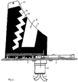
- a copper-clad circuit board 4 Extending substantially perpendicularly from the plane of the support plate 1, i. extending vertically, a copper-clad circuit board 4 is arranged.
- the pad structure 7 extends from a lower region of the printed circuit board to an upper end 8 and there transitions into a contact region, which connects to the corresponding end of the rod radiator 9 (see FIG Fig. 3 ) realized.
- the structures 6 and 7 are formed so that the electric field is orthogonally polarized. Both radiator structures are spatially separated.
- the mobile monopole radiator is contacted at the connection point 10 and the CB rod radiator 9 at the connection point 11.
- the mobile monopole radiating structure extends from a lower portion of the printed circuit board 4 in the vertical direction 61.
- This vertical profile 61 is followed by a first bend 62.
- This bend 62 merges into a further bend 63, which essentially takes up the direction of the course of the structure 61.
- the region 63 is followed by another angled structural unit 64.
- the pad structure 7 extends very close to the vertical outer edge 71 of the printed circuit board 4. To improve the decoupling the areas 61 and 7 are not parallel, but at an angle ⁇ .
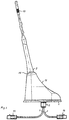
- the Fig. 2 shows the opposite side of the circuit board 4 with a grounded mobile zigzag slot radiator structure 12 for the purpose of radiator shortening. It is preferably a grounded structure, which is fed by the opposite radiator arrangement 6 using the printed circuit board dielectric. Networks for separate excitation of the slot structures are not required.
- the sections 62, 63 and 64 of the monopole radiator structure 6 are capable of forming the slot structures 12 and 13 in the desired manner, i. to feed in the frequency ranges realized here.
- the frequency ranges of the slot radiator antennas are determined by the length of the slot 12 on the one hand, i. in the low-frequency GSM area, and the slot 13 on the other hand, i. for the high-frequency GSM area, configurable.
- the mentioned zigzag slot radiator structure shortens the radiator length in the sense of a folded radiator.
- the respective impedance of the slot radiator is from the position of the exciter, see reference numeral 62 in FIG Fig. 1 , for the low-frequency slot radiator, and reference numeral 64 for the high-frequency slot radiator. Since the low-frequency and high-frequency GSM areas do not have to be decoupled, the monopole radiator structure 6 can be designed as a common exciter. The profile of the monopole radiator structure 6 according to the exemplary embodiment is optimized for an impedance of 50 ohms.
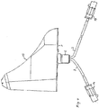
- the Fig. 3 shows a side view of the ready antenna with connecting leads 3 and Fakra plug-in devices 14.
- the radiator assemblies 6, 12 and 13 and the top of the support plate 1 are enclosed by the housing 15, consisting of a dielectric material.
- the Housing 15 may have a flow-optimized shape, eg in the so-called shark design.
- a receptacle 16 for the radiator 9 At the top of the housing 15 is a receptacle 16 for the radiator 9, which at its upper radiator end means for tuning 17, e.g. by extension or shortening of the radiator has.
- the radiator 9 is connected to the upper area 16 of the housing 15, e.g. fixed by screwing.
- the radiator 9 when not in use, the radiator 9 (see Fig. 4 ), without degrading the electrical characteristics of the GSM antennas.
Landscapes
- Physics & Mathematics (AREA)
- Electromagnetism (AREA)
- Engineering & Computer Science (AREA)
- Remote Sensing (AREA)
- Details Of Aerials (AREA)
- Support Of Aerials (AREA)
Claims (4)
- Antenne à plusieurs gammes pour un dispositif émetteur et/ou récepteur destiné à une utilisation mobile, en particulier dans des véhicules automobiles, constituée par une plaque de support isolante (1) destinée à recevoir des éléments de connexion électriques et à monter l'antenne,
dans laquelle une carte à circuits imprimés (4) est agencée sur la plaque de support (1) en s'étendant depuis celle-ci sensiblement perpendiculairement, et comportant un boîtier (15) en forme de capot en matériau diélectrique,
dans laquelle sont prévues, sur une première face (5) de la carte à circuits imprimés, une structure d'émetteur monopolaire de radiocommunication et une structure de surface de connexion (7) pour un émetteur en barreau CB (9) fixable sur la face supérieure du boîtier (15) en forme de capot,
dans laquelle la structure de surface de connexion (7) et la structure d'émetteur monopolaire (6) sont réalisées de telle sorte que le champ électrique est polarisé orthogonalement et que les deux émetteurs sont séparés dans l'espace et découplés l'un de l'autre,
dans laquelle la carte à circuits imprimés (4) présente des structures plaquées de cuivre,
et sur la seconde face (51) de la carte à circuits imprimés opposée à la première (5) est prévue une structure d'émetteur à fentes en zigzag (12) mise à la terre qui est excitée par la structure d'émetteur monopolaire (6),
de plus, la carte à circuits imprimés (4) approxime sensiblement et remplit la surface de section longitudinale du boîtier (15), et dans une zone de bord extérieur (71) de la carte à circuits imprimés (4), qui est sensiblement verticale dans l'état de fonctionnement, la structure de surface de connexion (7) pour l'émetteur CB (9) et la structure d'émetteur monopolaire avoisinant une partie de ladite structure s'étendent à partir d'une zone inférieure de la carte à circuits imprimés (4) en direction verticale (61), et au moins un coudage (62 ; 63 ; 64) orienté dans le plan de la carte à circuits imprimés se raccorde à ce tracé vertical de la structure d'émetteur monopolaire. - Antenne à plusieurs gammes selon la revendication 1,
dans laquelle, pour un fonctionnement CB optionnel, l'émetteur en barreau (9) est susceptible d'être fixé sur le boîtier (15) en forme de capot par vissage, par enfichage ou similaire. - Antenne à plusieurs gammes selon la revendication 2,
dans laquelle l'émetteur en barreau (9) comprend un moyen d'accord (17) à une extrémité de l'émetteur. - Antenne à plusieurs gammes selon l'une des revendications précédentes,
dans laquelle la structure de surface de connexion (7) s'étend jusqu'à la face supérieure de la carte à circuits imprimés (4) et y est en liaison avec une zone de contact ou un élément de contact (8) qui établit un contact électrique avec un émetteur en barreau CB (9).
Applications Claiming Priority (3)
| Application Number | Priority Date | Filing Date | Title |
|---|---|---|---|
| DE202014001466 | 2014-02-18 | ||
| DE202014002207.0U DE202014002207U1 (de) | 2014-02-18 | 2014-03-10 | Mehrbereichsantenne für eine Empfangs- und/oder Sendeeinrichtung für den mobilen Einsatz |
| PCT/EP2015/052752 WO2015124463A1 (fr) | 2014-02-18 | 2015-02-10 | Antenne à plusieurs gammes de fréquences pour un dispositif émetteur et/ou récepteur destiné à une utilisation mobile |
Publications (3)
| Publication Number | Publication Date |
|---|---|
| EP3108535A1 EP3108535A1 (fr) | 2016-12-28 |
| EP3108535B1 true EP3108535B1 (fr) | 2017-12-27 |
| EP3108535B8 EP3108535B8 (fr) | 2018-08-01 |
Family
ID=50556370
Family Applications (1)
| Application Number | Title | Priority Date | Filing Date |
|---|---|---|---|
| EP15705002.2A Not-in-force EP3108535B8 (fr) | 2014-02-18 | 2015-02-10 | Antenne à plusieurs gammes de fréquences pour un dispositif émetteur et/ou récepteur destiné à une utilisation mobile |
Country Status (3)
| Country | Link |
|---|---|
| EP (1) | EP3108535B8 (fr) |
| DE (1) | DE202014002207U1 (fr) |
| WO (1) | WO2015124463A1 (fr) |
Families Citing this family (5)
| Publication number | Priority date | Publication date | Assignee | Title |
|---|---|---|---|---|
| DE202014008788U1 (de) | 2014-10-13 | 2014-11-27 | Antennentechnik Bad Blankenburg Gmbh | Mehrfachband-Finnenantenne für den mobilen Einsatz, insbesondere für Fahrzeuge |
| DE202015001905U1 (de) | 2014-12-12 | 2015-05-11 | Antennentechnik Bad Blankenburg Gmbh | Kurzstab-Monopolantenne für den Einsatz im mobilen Bereich |
| JP6402154B2 (ja) * | 2016-09-16 | 2018-10-10 | 株式会社フジクラ | アンテナ装置及び車載用アンテナ装置 |
| JP6401835B1 (ja) * | 2017-08-07 | 2018-10-10 | 株式会社ヨコオ | アンテナ装置 |
| DE202018101775U1 (de) | 2018-03-13 | 2018-04-16 | Antennentechnik Abb Bad Blankenburg Gmbh | Mehrbereichsantenne für eine Empfangs- und/oder Sendeeinrichtung für den mobilen Einsatz, insbesondere Fahrzeugen, bestehend aus einer beidseitig kupferkaschierten Leiterplatte |
Family Cites Families (11)
| Publication number | Priority date | Publication date | Assignee | Title |
|---|---|---|---|---|
| DE4102845B4 (de) | 1991-01-31 | 2004-02-19 | Fuba Automotive Gmbh & Co. Kg | Kraftfahrzeug-Stabantenne für mehrere getrennte Frequenzbereiche |
| DE4141783B4 (de) | 1991-01-31 | 2004-04-15 | Fuba Automotive Gmbh & Co. Kg | Kraftfahrzeug-Antenne für mehrere getrennte Frequenzbereiche |
| DE4109630A1 (de) | 1991-03-23 | 1992-09-24 | Bosch Gmbh Robert | Stabfoermiger mehrbereichsstrahler |
| FR2727250A1 (fr) * | 1994-11-22 | 1996-05-24 | Brachat Patrice | Antenne large bande monopole en technologie imprimee uniplanaire et dispositif d'emission et/ou de reception incorporant une telle antenne |
| CN1307743C (zh) * | 2001-02-26 | 2007-03-28 | 日本安特尼株式会社 | 多频率天线 |
| DE10207703B4 (de) | 2002-02-22 | 2005-06-09 | Kathrein-Werke Kg | Antenne für eine Empfangs- und/oder Sendeeinrichtung insbesondere als Dachantenne für Kraftfahrzeuge |
| DE102005054286B4 (de) | 2005-11-11 | 2011-04-07 | Delphi Delco Electronics Europe Gmbh | Antennenanordnung |
| ITVI20050300A1 (it) * | 2005-11-11 | 2007-05-12 | Calearo Antenne Spa | Antenna multibanda veicolare per la telefonia mobile |
| DE102007061740B4 (de) | 2007-12-20 | 2022-12-01 | Robert Bosch Gmbh | Mehrbereichsantenne sowie Verfahren |
| TWI483464B (zh) * | 2011-10-20 | 2015-05-01 | Acer Inc | 通訊裝置及其天線結構 |
| JP5961027B2 (ja) * | 2012-04-13 | 2016-08-02 | 株式会社日本自動車部品総合研究所 | アンテナ装置 |
-
2014
- 2014-03-10 DE DE202014002207.0U patent/DE202014002207U1/de not_active Expired - Lifetime
-
2015
- 2015-02-10 WO PCT/EP2015/052752 patent/WO2015124463A1/fr not_active Ceased
- 2015-02-10 EP EP15705002.2A patent/EP3108535B8/fr not_active Not-in-force
Also Published As
| Publication number | Publication date |
|---|---|
| WO2015124463A1 (fr) | 2015-08-27 |
| EP3108535B8 (fr) | 2018-08-01 |
| DE202014002207U1 (de) | 2014-04-09 |
| EP3108535A1 (fr) | 2016-12-28 |
Similar Documents
| Publication | Publication Date | Title |
|---|---|---|
| DE60315791T2 (de) | Chipantenne | |
| EP1619752B1 (fr) | Module d'antenne | |
| DE60023062T2 (de) | Antennenkonstruktion | |
| EP0952625B1 (fr) | Antenne pour plusieurs services radio | |
| DE102005060648B4 (de) | Antennenvorrichtung mit für Ultrabreitband-Kommunikation geeigneten Strahlungseigenschaften | |
| DE102015220372B3 (de) | Multiband-GNSS Antenne | |
| DE102005015561A1 (de) | Interne Breitbandantenne | |
| DE19713929A1 (de) | Sende-Empfangs-Einrichtung | |
| DE10150149A1 (de) | Antennenmodul | |
| EP3108535B1 (fr) | Antenne à plusieurs gammes de fréquences pour un dispositif émetteur et/ou récepteur destiné à une utilisation mobile | |
| DE102008007258A1 (de) | Mehrband-Antenne sowie mobiles Kommunikationsendgerät, welches diese aufweist | |
| EP1829158B1 (fr) | Structure d'antenne disque unipolaire | |
| DE10205358A1 (de) | Mäanderförmige Dualband-Antenne | |
| DE19961488A1 (de) | Antenne für ein Kommunikationsendgerät | |
| DE112008001688T5 (de) | Antennensystem für die Fernsteuerung einer Anwendung im Automobilbereich | |
| DE102005047418B4 (de) | Mehrband-Antenneneinrichtung, drahtlose Datenübertragungseinrichtung sowie Radiofrequenz-Chip | |
| DE60105447T2 (de) | Gedruckte patch-antenne | |
| DE102007055327A1 (de) | Externes mehrbandiges Funkantennenmodul | |
| DE102012207954A1 (de) | Antennenvorrichtung | |
| EP2367233A1 (fr) | Système d'antenes planaires | |
| DE102004036001A1 (de) | Breitbandige Antenne mit geringer Bauhöhe | |
| DE60033140T2 (de) | Mehrfrequenzband-Antenne | |
| EP3231036B1 (fr) | Antenne bâton monopôle pour une mise en oeuvre dans le domaine mobile | |
| DE102010036600A1 (de) | Dualbandantenne | |
| DE19722506A1 (de) | Funkgerät |
Legal Events
| Date | Code | Title | Description |
|---|---|---|---|
| PUAI | Public reference made under article 153(3) epc to a published international application that has entered the european phase |
Free format text: ORIGINAL CODE: 0009012 |
|
| 17P | Request for examination filed |
Effective date: 20150806 |
|
| AK | Designated contracting states |
Kind code of ref document: A1 Designated state(s): AL AT BE BG CH CY CZ DE DK EE ES FI FR GB GR HR HU IE IS IT LI LT LU LV MC MK MT NL NO PL PT RO RS SE SI SK SM TR |
|
| AX | Request for extension of the european patent |
Extension state: BA ME |
|
| 17Q | First examination report despatched |
Effective date: 20170215 |
|
| DAX | Request for extension of the european patent (deleted) | ||
| GRAP | Despatch of communication of intention to grant a patent |
Free format text: ORIGINAL CODE: EPIDOSNIGR1 |
|
| INTG | Intention to grant announced |
Effective date: 20170802 |
|
| GRAA | (expected) grant |
Free format text: ORIGINAL CODE: 0009210 |
|
| GRAS | Grant fee paid |
Free format text: ORIGINAL CODE: EPIDOSNIGR3 |
|
| AK | Designated contracting states |
Kind code of ref document: B1 Designated state(s): AL AT BE BG CH CY CZ DE DK EE ES FI FR GB GR HR HU IE IS IT LI LT LU LV MC MK MT NL NO PL PT RO RS SE SI SK SM TR |
|
| REG | Reference to a national code |
Ref country code: GB Ref legal event code: FG4D Free format text: NOT ENGLISH |
|
| REG | Reference to a national code |
Ref country code: CH Ref legal event code: EP |
|
| REG | Reference to a national code |
Ref country code: AT Ref legal event code: REF Ref document number: 959042 Country of ref document: AT Kind code of ref document: T Effective date: 20180115 |
|
| REG | Reference to a national code |
Ref country code: IE Ref legal event code: FG4D Free format text: LANGUAGE OF EP DOCUMENT: GERMAN |
|
| REG | Reference to a national code |
Ref country code: DE Ref legal event code: R096 Ref document number: 502015002701 Country of ref document: DE |
|
| PG25 | Lapsed in a contracting state [announced via postgrant information from national office to epo] |
Ref country code: NO Free format text: LAPSE BECAUSE OF FAILURE TO SUBMIT A TRANSLATION OF THE DESCRIPTION OR TO PAY THE FEE WITHIN THE PRESCRIBED TIME-LIMIT Effective date: 20180327 Ref country code: FI Free format text: LAPSE BECAUSE OF FAILURE TO SUBMIT A TRANSLATION OF THE DESCRIPTION OR TO PAY THE FEE WITHIN THE PRESCRIBED TIME-LIMIT Effective date: 20171227 Ref country code: LT Free format text: LAPSE BECAUSE OF FAILURE TO SUBMIT A TRANSLATION OF THE DESCRIPTION OR TO PAY THE FEE WITHIN THE PRESCRIBED TIME-LIMIT Effective date: 20171227 |
|
| REG | Reference to a national code |
Ref country code: NL Ref legal event code: MP Effective date: 20171227 |
|
| REG | Reference to a national code |
Ref country code: LT Ref legal event code: MG4D |
|
| PG25 | Lapsed in a contracting state [announced via postgrant information from national office to epo] |
Ref country code: GR Free format text: LAPSE BECAUSE OF FAILURE TO SUBMIT A TRANSLATION OF THE DESCRIPTION OR TO PAY THE FEE WITHIN THE PRESCRIBED TIME-LIMIT Effective date: 20180328 Ref country code: LV Free format text: LAPSE BECAUSE OF FAILURE TO SUBMIT A TRANSLATION OF THE DESCRIPTION OR TO PAY THE FEE WITHIN THE PRESCRIBED TIME-LIMIT Effective date: 20171227 Ref country code: HR Free format text: LAPSE BECAUSE OF FAILURE TO SUBMIT A TRANSLATION OF THE DESCRIPTION OR TO PAY THE FEE WITHIN THE PRESCRIBED TIME-LIMIT Effective date: 20171227 Ref country code: BG Free format text: LAPSE BECAUSE OF FAILURE TO SUBMIT A TRANSLATION OF THE DESCRIPTION OR TO PAY THE FEE WITHIN THE PRESCRIBED TIME-LIMIT Effective date: 20180327 Ref country code: RS Free format text: LAPSE BECAUSE OF FAILURE TO SUBMIT A TRANSLATION OF THE DESCRIPTION OR TO PAY THE FEE WITHIN THE PRESCRIBED TIME-LIMIT Effective date: 20171227 |
|
| GRAT | Correction requested after decision to grant or after decision to maintain patent in amended form |
Free format text: ORIGINAL CODE: EPIDOSNCDEC |
|
| PG25 | Lapsed in a contracting state [announced via postgrant information from national office to epo] |
Ref country code: NL Free format text: LAPSE BECAUSE OF FAILURE TO SUBMIT A TRANSLATION OF THE DESCRIPTION OR TO PAY THE FEE WITHIN THE PRESCRIBED TIME-LIMIT Effective date: 20171227 |
|
| RAP2 | Party data changed (patent owner data changed or rights of a patent transferred) |
Owner name: ANTENNENTECHNIK ABB BAD BLANKENBURG GMBH |
|
| PG25 | Lapsed in a contracting state [announced via postgrant information from national office to epo] |
Ref country code: CZ Free format text: LAPSE BECAUSE OF FAILURE TO SUBMIT A TRANSLATION OF THE DESCRIPTION OR TO PAY THE FEE WITHIN THE PRESCRIBED TIME-LIMIT Effective date: 20171227 Ref country code: ES Free format text: LAPSE BECAUSE OF FAILURE TO SUBMIT A TRANSLATION OF THE DESCRIPTION OR TO PAY THE FEE WITHIN THE PRESCRIBED TIME-LIMIT Effective date: 20171227 Ref country code: SK Free format text: LAPSE BECAUSE OF FAILURE TO SUBMIT A TRANSLATION OF THE DESCRIPTION OR TO PAY THE FEE WITHIN THE PRESCRIBED TIME-LIMIT Effective date: 20171227 Ref country code: CY Free format text: LAPSE BECAUSE OF FAILURE TO SUBMIT A TRANSLATION OF THE DESCRIPTION OR TO PAY THE FEE WITHIN THE PRESCRIBED TIME-LIMIT Effective date: 20171227 Ref country code: EE Free format text: LAPSE BECAUSE OF FAILURE TO SUBMIT A TRANSLATION OF THE DESCRIPTION OR TO PAY THE FEE WITHIN THE PRESCRIBED TIME-LIMIT Effective date: 20171227 |
|
| PG25 | Lapsed in a contracting state [announced via postgrant information from national office to epo] |
Ref country code: IS Free format text: LAPSE BECAUSE OF FAILURE TO SUBMIT A TRANSLATION OF THE DESCRIPTION OR TO PAY THE FEE WITHIN THE PRESCRIBED TIME-LIMIT Effective date: 20180427 Ref country code: PL Free format text: LAPSE BECAUSE OF FAILURE TO SUBMIT A TRANSLATION OF THE DESCRIPTION OR TO PAY THE FEE WITHIN THE PRESCRIBED TIME-LIMIT Effective date: 20171227 Ref country code: IT Free format text: LAPSE BECAUSE OF FAILURE TO SUBMIT A TRANSLATION OF THE DESCRIPTION OR TO PAY THE FEE WITHIN THE PRESCRIBED TIME-LIMIT Effective date: 20171227 Ref country code: SM Free format text: LAPSE BECAUSE OF FAILURE TO SUBMIT A TRANSLATION OF THE DESCRIPTION OR TO PAY THE FEE WITHIN THE PRESCRIBED TIME-LIMIT Effective date: 20171227 |
|
| REG | Reference to a national code |
Ref country code: DE Ref legal event code: R081 Ref document number: 502015002701 Country of ref document: DE Owner name: ANTENNENTECHNIK BAD BLANKENBURG GMBH, DE Free format text: FORMER OWNER: ANTENNENTECHNIK BAD BLANKENBURG GMBH, 07422 BAD BLANKENBURG, DE Ref country code: DE Ref legal event code: R082 Ref document number: 502015002701 Country of ref document: DE Representative=s name: MEISSNER BOLTE PATENTANWAELTE RECHTSANWAELTE P, DE |
|
| REG | Reference to a national code |
Ref country code: CH Ref legal event code: PL |
|
| PG25 | Lapsed in a contracting state [announced via postgrant information from national office to epo] |
Ref country code: MT Free format text: LAPSE BECAUSE OF FAILURE TO SUBMIT A TRANSLATION OF THE DESCRIPTION OR TO PAY THE FEE WITHIN THE PRESCRIBED TIME-LIMIT Effective date: 20171227 Ref country code: MC Free format text: LAPSE BECAUSE OF FAILURE TO SUBMIT A TRANSLATION OF THE DESCRIPTION OR TO PAY THE FEE WITHIN THE PRESCRIBED TIME-LIMIT Effective date: 20171227 |
|
| REG | Reference to a national code |
Ref country code: DE Ref legal event code: R097 Ref document number: 502015002701 Country of ref document: DE |
|
| PLBE | No opposition filed within time limit |
Free format text: ORIGINAL CODE: 0009261 |
|
| STAA | Information on the status of an ep patent application or granted ep patent |
Free format text: STATUS: NO OPPOSITION FILED WITHIN TIME LIMIT |
|
| REG | Reference to a national code |
Ref country code: IE Ref legal event code: MM4A |
|
| REG | Reference to a national code |
Ref country code: BE Ref legal event code: MM Effective date: 20180228 |
|
| PG25 | Lapsed in a contracting state [announced via postgrant information from national office to epo] |
Ref country code: LU Free format text: LAPSE BECAUSE OF NON-PAYMENT OF DUE FEES Effective date: 20180210 Ref country code: CH Free format text: LAPSE BECAUSE OF NON-PAYMENT OF DUE FEES Effective date: 20180228 Ref country code: LI Free format text: LAPSE BECAUSE OF NON-PAYMENT OF DUE FEES Effective date: 20180228 Ref country code: DK Free format text: LAPSE BECAUSE OF FAILURE TO SUBMIT A TRANSLATION OF THE DESCRIPTION OR TO PAY THE FEE WITHIN THE PRESCRIBED TIME-LIMIT Effective date: 20171227 |
|
| REG | Reference to a national code |
Ref country code: FR Ref legal event code: ST Effective date: 20181031 |
|
| 26N | No opposition filed |
Effective date: 20180928 |
|
| PG25 | Lapsed in a contracting state [announced via postgrant information from national office to epo] |
Ref country code: IE Free format text: LAPSE BECAUSE OF NON-PAYMENT OF DUE FEES Effective date: 20180210 |
|
| PG25 | Lapsed in a contracting state [announced via postgrant information from national office to epo] |
Ref country code: BE Free format text: LAPSE BECAUSE OF NON-PAYMENT OF DUE FEES Effective date: 20180228 Ref country code: SI Free format text: LAPSE BECAUSE OF FAILURE TO SUBMIT A TRANSLATION OF THE DESCRIPTION OR TO PAY THE FEE WITHIN THE PRESCRIBED TIME-LIMIT Effective date: 20171227 Ref country code: FR Free format text: LAPSE BECAUSE OF NON-PAYMENT OF DUE FEES Effective date: 20180228 |
|
| GBPC | Gb: european patent ceased through non-payment of renewal fee |
Effective date: 20190210 |
|
| PG25 | Lapsed in a contracting state [announced via postgrant information from national office to epo] |
Ref country code: GB Free format text: LAPSE BECAUSE OF NON-PAYMENT OF DUE FEES Effective date: 20190210 |
|
| REG | Reference to a national code |
Ref country code: DE Ref legal event code: R081 Ref document number: 502015002701 Country of ref document: DE Owner name: DESAY SV AUTOMOTIVE EUROPE GMBH, DE Free format text: FORMER OWNER: ANTENNENTECHNIK ABB BAD BLANKENBURG GMBH, 99428 WEIMAR, DE Ref country code: DE Ref legal event code: R082 Ref document number: 502015002701 Country of ref document: DE Representative=s name: MEISSNER BOLTE PATENTANWAELTE RECHTSANWAELTE P, DE Ref country code: DE Ref legal event code: R081 Ref document number: 502015002701 Country of ref document: DE Owner name: ANTENNENTECHNIK BAD BLANKENBURG GMBH, DE Free format text: FORMER OWNER: ANTENNENTECHNIK ABB BAD BLANKENBURG GMBH, 99428 WEIMAR, DE |
|
| PG25 | Lapsed in a contracting state [announced via postgrant information from national office to epo] |
Ref country code: TR Free format text: LAPSE BECAUSE OF FAILURE TO SUBMIT A TRANSLATION OF THE DESCRIPTION OR TO PAY THE FEE WITHIN THE PRESCRIBED TIME-LIMIT Effective date: 20171227 |
|
| PG25 | Lapsed in a contracting state [announced via postgrant information from national office to epo] |
Ref country code: PT Free format text: LAPSE BECAUSE OF FAILURE TO SUBMIT A TRANSLATION OF THE DESCRIPTION OR TO PAY THE FEE WITHIN THE PRESCRIBED TIME-LIMIT Effective date: 20171227 |
|
| PG25 | Lapsed in a contracting state [announced via postgrant information from national office to epo] |
Ref country code: MK Free format text: LAPSE BECAUSE OF NON-PAYMENT OF DUE FEES Effective date: 20171227 Ref country code: RO Free format text: LAPSE BECAUSE OF FAILURE TO SUBMIT A TRANSLATION OF THE DESCRIPTION OR TO PAY THE FEE WITHIN THE PRESCRIBED TIME-LIMIT Effective date: 20171227 Ref country code: HU Free format text: LAPSE BECAUSE OF FAILURE TO SUBMIT A TRANSLATION OF THE DESCRIPTION OR TO PAY THE FEE WITHIN THE PRESCRIBED TIME-LIMIT; INVALID AB INITIO Effective date: 20150210 Ref country code: SE Free format text: LAPSE BECAUSE OF FAILURE TO SUBMIT A TRANSLATION OF THE DESCRIPTION OR TO PAY THE FEE WITHIN THE PRESCRIBED TIME-LIMIT Effective date: 20171227 |
|
| PG25 | Lapsed in a contracting state [announced via postgrant information from national office to epo] |
Ref country code: AL Free format text: LAPSE BECAUSE OF FAILURE TO SUBMIT A TRANSLATION OF THE DESCRIPTION OR TO PAY THE FEE WITHIN THE PRESCRIBED TIME-LIMIT Effective date: 20171227 |
|
| REG | Reference to a national code |
Ref country code: AT Ref legal event code: HC Ref document number: 959042 Country of ref document: AT Kind code of ref document: T Owner name: ANTENNENTECHNIK BAD BLANKENBURG GMBH, DE Effective date: 20200618 |
|
| PGFP | Annual fee paid to national office [announced via postgrant information from national office to epo] |
Ref country code: AT Payment date: 20230215 Year of fee payment: 9 |
|
| PGFP | Annual fee paid to national office [announced via postgrant information from national office to epo] |
Ref country code: DE Payment date: 20230227 Year of fee payment: 9 |
|
| P01 | Opt-out of the competence of the unified patent court (upc) registered |
Effective date: 20230530 |
|
| REG | Reference to a national code |
Ref country code: DE Ref legal event code: R081 Ref document number: 502015002701 Country of ref document: DE Owner name: DESAY SV AUTOMOTIVE EUROPE GMBH, DE Free format text: FORMER OWNER: ANTENNENTECHNIK BAD BLANKENBURG GMBH, 99428 WEIMAR, DE |
|
| REG | Reference to a national code |
Ref country code: DE Ref legal event code: R119 Ref document number: 502015002701 Country of ref document: DE |
|
| REG | Reference to a national code |
Ref country code: AT Ref legal event code: MM01 Ref document number: 959042 Country of ref document: AT Kind code of ref document: T Effective date: 20240210 |
|
| PG25 | Lapsed in a contracting state [announced via postgrant information from national office to epo] |
Ref country code: AT Free format text: LAPSE BECAUSE OF NON-PAYMENT OF DUE FEES Effective date: 20240210 |
|
| PG25 | Lapsed in a contracting state [announced via postgrant information from national office to epo] |
Ref country code: AT Free format text: LAPSE BECAUSE OF NON-PAYMENT OF DUE FEES Effective date: 20240210 |
|
| PG25 | Lapsed in a contracting state [announced via postgrant information from national office to epo] |
Ref country code: DE Free format text: LAPSE BECAUSE OF NON-PAYMENT OF DUE FEES Effective date: 20240903 |
|
| PG25 | Lapsed in a contracting state [announced via postgrant information from national office to epo] |
Ref country code: DE Free format text: LAPSE BECAUSE OF NON-PAYMENT OF DUE FEES Effective date: 20240903 |