EP3108669B1 - Dispositif et procédé pour régler un étage d'atténuation dépendant de la fréquence - Google Patents
Dispositif et procédé pour régler un étage d'atténuation dépendant de la fréquence Download PDFInfo
- Publication number
- EP3108669B1 EP3108669B1 EP15707892.4A EP15707892A EP3108669B1 EP 3108669 B1 EP3108669 B1 EP 3108669B1 EP 15707892 A EP15707892 A EP 15707892A EP 3108669 B1 EP3108669 B1 EP 3108669B1
- Authority
- EP
- European Patent Office
- Prior art keywords
- frequency
- reproduction system
- audio reproduction
- linear distortion
- input data
- Prior art date
- Legal status (The legal status is an assumption and is not a legal conclusion. Google has not performed a legal analysis and makes no representation as to the accuracy of the status listed.)
- Active
Links
Images
Classifications
-
- G—PHYSICS
- G10—MUSICAL INSTRUMENTS; ACOUSTICS
- G10L—SPEECH ANALYSIS TECHNIQUES OR SPEECH SYNTHESIS; SPEECH RECOGNITION; SPEECH OR VOICE PROCESSING TECHNIQUES; SPEECH OR AUDIO CODING OR DECODING
- G10L21/00—Speech or voice signal processing techniques to produce another audible or non-audible signal, e.g. visual or tactile, in order to modify its quality or its intelligibility
- G10L21/02—Speech enhancement, e.g. noise reduction or echo cancellation
- G10L21/0208—Noise filtering
- G10L21/0216—Noise filtering characterised by the method used for estimating noise
- G10L21/0232—Processing in the frequency domain
-
- H—ELECTRICITY
- H04—ELECTRIC COMMUNICATION TECHNIQUE
- H04R—LOUDSPEAKERS, MICROPHONES, GRAMOPHONE PICK-UPS OR LIKE ACOUSTIC ELECTROMECHANICAL TRANSDUCERS; ELECTRIC HEARING AIDS; PUBLIC ADDRESS SYSTEMS
- H04R3/00—Circuits for transducers
- H04R3/04—Circuits for transducers for correcting frequency response
-
- H—ELECTRICITY
- H03—ELECTRONIC CIRCUITRY
- H03G—CONTROL OF AMPLIFICATION
- H03G5/00—Tone control or bandwidth control in amplifiers
- H03G5/005—Tone control or bandwidth control in amplifiers of digital signals
-
- H—ELECTRICITY
- H03—ELECTRONIC CIRCUITRY
- H03G—CONTROL OF AMPLIFICATION
- H03G5/00—Tone control or bandwidth control in amplifiers
- H03G5/16—Automatic control
- H03G5/165—Equalizers; Volume or gain control in limited frequency bands
-
- H—ELECTRICITY
- H04—ELECTRIC COMMUNICATION TECHNIQUE
- H04R—LOUDSPEAKERS, MICROPHONES, GRAMOPHONE PICK-UPS OR LIKE ACOUSTIC ELECTROMECHANICAL TRANSDUCERS; ELECTRIC HEARING AIDS; PUBLIC ADDRESS SYSTEMS
- H04R2430/00—Signal processing covered by H04R, not provided for in its groups
-
- H—ELECTRICITY
- H04—ELECTRIC COMMUNICATION TECHNIQUE
- H04S—STEREOPHONIC SYSTEMS
- H04S2400/00—Details of stereophonic systems covered by H04S but not provided for in its groups
- H04S2400/09—Electronic reduction of distortion of stereophonic sound systems
Definitions
- Example embodiments disclosed herein generally relates to audio reproduction systems and in particular to suppression of distortion occurring in audio reproduction systems.
- Non-linear distortion may cause sound characteristics such as timbre and phase to change as a function of the sound amplitude.
- Non-linear distortion may also cause a non-linear magnitude response (with respect to intensity) at a given frequency, and may create new frequency components in the sound output, for example, at integer multiples of the frequencies of input frequency components (harmonics).
- a typical source of non-linear distortion in a commercial sound reproduction system is forcing a loudspeaker unit to operate outside its linear operation range in order to achieve a louder sound output without increasing costs for the transducer.
- One way to suppress non-linear distortion is to attenuate the input signal before it is fed to the loudspeaker, but this also makes the system quieter, which is typically not acceptable.
- An approach to suppressing non-linear distortion while sacrificing only a little of the system's loudness is to use a dynamic range limiter which monitors the input signal and applies attenuation only for the loud parts, so that the amplitude of the signal fed to the loudspeaker never exceeds a given threshold value.
- the French patent publication No. 2890280A1 is an example of prior art, and discloses an audio processing unit for a sound reproduction system.
- the unit has a psychoacoustic model whose parameters are modified by a user, and a filter assembly for digital filtering amplitude and phase of an audio signal based on its frequency, where the model and the filter assembly are provided to each of low frequency and high frequency loudspeakers in upstream of power amplifiers.
- the filter assembly includes a finite impulse response (FIR) filter or FIR-infinite impulse response (FIR-IIR) hybrid filter.
- the model linearizes a response curve of a loudspeaker enclosure according to a direction of perception of sound by a user.
- a method for calibrating the audio processing unit, and an audio processing method for linearizing a stereo system are also disclosed.
- the United States patent publication No. 577126A is another example of prior art, and discloses an overload protection circuit for transducers.
- a reference filter connected to the electric input of a transducer provides a monitored signal related to the load of the transducer. If the amplitude of the monitored signal exceeds a prescribed threshold value, a feedback loop is activated to protect the transducer from overload and destruction.
- the feedback loop is realized by the reference filter, a multiplier and a summer.
- an audio signal may be a pure audio signal, an audio part of an audiovisual signal or multimedia signal or any of these in combination with metadata.
- a device for tuning a frequency-dependent attenuation stage with the purpose of suppressing non-linear distortion occurring in an audio reproduction system associated with the frequency-dependent attenuation stage is provided.
- the audio reproduction system associated with the frequency-dependent attenuation stage tuned by the device is arranged to supply an output acoustic signal in response to an input data signal.
- the device comprises a receiving section adapted to receive data representing an output acoustic signal recorded upon excitation of the audio reproduction system by a predetermined input data signal.
- the device also comprises a first distortion detection section adapted to detect presence of non-linear distortion based on the received data and to apply psycho-acoustic compensation to the detected non-linear distortion.
- the device further comprises a control section adapted to determine, based on the psycho-acoustically compensated non-linear distortion, control information suitable for controlling the frequency-dependent attenuation stage.
- a frequency-dependent attenuation stage is meant, inter alia, a processing stage adapted to perform frequency-dependent attenuation on an audio signal or an audio part of a multimedia signal, for example, a multi-band limiter.
- the frequency-dependent attenuation stage attenuates signals to be played back by the audio reproduction system in order to reduce the amount of non-linear distortion created in the audio reproduction system, rather than attenuating non-linear distortion already present.
- non-linear distortion distortion caused by non-linear effects of audio reproduction systems, for example, effects causing changes in sound characteristics such as timbre and/or phase as a function of sound amplitude.
- Non-linear distortion may for example include harmonic distortion components located at or near frequencies that are integer multiples of the input frequencies.
- the tuning of the frequency-dependent attenuation stage takes into account the distortion behavior of that particular audio reproduction system and allows for a more efficient suppression of non-linear distortion occurring in that particular audio reproduction system.
- the frequency-dependent attenuation stage may be tuned to more efficiently suppress perceptible/audible non-linear distortion and/or to reduce unnecessary attenuation of audio content which would mainly have caused non-audible or not particularly annoying non-linear distortion.
- the application of psycho-acoustic compensation during tuning of the frequency-dependent attenuation stage may improve the balance between audible non-linear distortion created by the audio reproduction system and the overall loudness of the audio reproduction system.
- the predetermined input data signal may for example be known a priori by the device and may for example be provided by the device to the audio reproduction system as a part of a predetermined procedure of tuning the frequency-dependent attenuation stage.
- information about the predetermined input data signal may for example, be obtained by the device based on the received data and/or may be received separately by the device.
- the first distortion detection section may be adapted to apply psycho-acoustic compensation by at least disregarding spectral content of the detected non-linear distortion below a frequency-dependent audibility threshold.
- the frequency-dependent audibility threshold may for example be set as an amplitude/power/energy level at which audio content at the given frequency becomes audible/perceptible to an average human listener.
- the audibility threshold may be set lower so that only audio content well-below hearing level is disregarded, or the audibility threshold may be set at a higher level so that audio content perceived by an average listener as sufficiently weak/quiet is disregarded.
- Disregarding spectral content below the frequency-dependent audibility threshold may include disregarding those frequency components of the detected non-linear distortion having an amplitude/power/energy level below the frequency-dependent audibility threshold. For instance, it may be assumed in subsequent processing steps that the distortion spectrum is zero in the corresponding frequency ranges.
- disregarding spectral content below the frequency-dependent audibility threshold may also include reducing the amplitude/power/energy levels of detected non-linear distortion components by levels of the frequency-dependent audibility threshold at frequencies corresponding to the respective non-linear distortion components, i.e. it may include a form of normalization with respect to the frequency-dependent audibility threshold.
- Subsequent processing steps may for example, be based on the reduced/normalized amplitude/power/energy levels of the detected non-linear distortion components.
- the first distortion detection section may be adapted to calibrate the frequency-dependent audibility threshold based on a sound pressure level estimated in connection with the recording of the output acoustic signal represented by the received data.
- the sound pressure level may serve as a link between the received data representing the output acoustic signal and physical quantities relevant for estimating how the output acoustic signal is perceived by a listener, and may facilitate an appropriate calibration of the frequency-dependent audibility threshold.
- the first distortion detection section may be adapted to apply psycho-acoustic compensation by at least: obtaining knowledge of a first frequency component of the predetermined input data signal; estimating, based on the first frequency component, a masking threshold for a neighborhood of the first frequency component; and disregarding spectral content of the detected non-linear distortion below the masking threshold thus estimated.
- the first frequency component of the predetermined input data signal gives rise to spectral content of the received data that is localized substantially at the same frequency as the first frequency component, and this spectral content has a masking effect on other audio content of the received audio signal.
- Disregarding spectral content below the masking threshold may include disregarding those frequency components of the detected nonlinear distortion having an amplitude/power/energy level below the masking threshold.
- the predetermined input audio signal and the first frequency component may be known a priori by the device and/or by the first distortion detection section, and may for example, be provided to the audio reproduction system by an interface comprised in the device.
- knowledge of the first frequency component may be received by the first distortion detection section or may be obtained based on the received data.
- the first distortion detection section may be adapted to: obtain knowledge of a first frequency component of the predetermined input data signal; and detect, based on the received data, non-linear distortion components corresponding to the first frequency component.
- the first distortion detection section may be adapted to detect, based on the received data, non-linear distortion components resulting from excitation of the audio reproduction system by the first frequency component
- the first frequency component of the predetermined input data signal gives rise to spectral content of the received data that is localized substantially at the same frequency as the first frequency component as well as non-linear distortion components located at other frequencies, for example, harmonic components located at or near integer multiples of the frequency of the first frequency component.
- the first distortion detection section may be adapted to determine a power ratio between the power of such spectral content of the received data that is localized substantially at the same frequency as the first frequency component and a sum of powers of the non-linear distortion components.
- the control section may be adapted to determine the control information also based on the power ratio.
- the first distortion detection section may be adapted to apply psycho-acoustic compensation at least by normalizing, prior to forming the power ratio, the power of the spectral content of the received data localized substantially at the same frequency as the first frequency component, and by further normalizing the powers of the non-linear distortion components, wherein the normalizations are performed with respect to a frequency-dependent audibility threshold.
- both the numerator and the denominator are reduced by normalizing the respective spectral content or components with respect to the frequency-dependent audibility threshold.
- the obtained value of the power ratio may more adequately indicate a power ratio (or a difference in intensity) between desired sound output and non-linear distortion, as perceived by a listener.
- the first distortion detection section may be adapted to calibrate the frequency-dependent audibility threshold based on a sound pressure level estimated in connection with the recording of the output acoustic signal represented by the received data.
- the first distortion detection section may be adapted to apply psycho-acoustic compensation by at least: assigning harmonic indices to the non-linear distortion components; and applying weights to the non-linear distortion components based on the harmonic indices, for example, prior to forming a power ratio.
- the harmonic indices relate the frequencies at which the non-linear distortion components (also called harmonic distortion components) are located to a basic frequency present in the excitation signal input to the audio reproduction system. Different harmonic distortion components are typically not perceived as equally disturbing by listeners.
- the second harmonic component for example, is often reported as having a much more subtle effect on the sound than higher-order harmonic components. This may be taken into account by weighting the non-linear distortion components based on their harmonic indices, for example, by giving the second harmonic component relatively less weight
- At least one of the non-linear distortion components may, based on its harmonic index, be disregarded.
- the first distortion detection section may be adapted to apply psycho-acoustic compensation at least by estimating a loudness of the spectral content of the received data localized substantially at the same frequency as the first frequency component, and estimating a combined loudness of the non-linear distortion components.
- the control section may be adapted to determine the control information also based on a difference between the estimated loudnesses. Loudness as perceived by a listener is typically frequency-dependent and may be accounted for by for example, rescaling or weighting the non-linear distortion components based on the respective frequency regions that they are located in.
- the combined loudness of the non-linear distortion components may for example be estimated using a loudness summation scheme.
- the device may comprise a second distortion detection section adapted to: obtain knowledge of a frequency range covering the spectral content of the predetermined input data signal, and detect non-linear distortion based on spectral content of the received data above the frequency range.
- the control section may be adapted to determine the control information also based on the non-linear distortion detected by the second distortion detection section.
- the predetermined input data signal may comprise relatively weak noise, for example, noise with a total energy of at most 5 or 10 percent of the total energy of the predetermined input data signal.
- the frequency range referred to here and in the claims need not include frequencies where only noise is present.
- Occurrence of spectral content of the received data for frequencies above the frequency range covering the spectral content of the predetermined input data signal may be indicative of non-linear distortion.
- the detection of non-linear distortion by the second distortion detection section may serve as a complement to the detection of non-linear distortion by the first distortion detection section.
- the device may be adapted to receive data recorded upon excitation of the audio reproduction system by a sequence of predetermined input data signals, wherein consecutive predetermined input data signals in the sequence corresponds to increasingly amplified versions of a predetermined waveform.
- the device may comprise a spectral composition analysis section adapted to: monitor, based on the received data, the spectral composition of the output audio signals of the audio reproduction system resulting from excitation by the sequence of predetermined input data signals; detect an abrupt change in the monitored spectral composition; and determine an amplification value of the predetermined waveform corresponding to the detected abrupt change.
- the control section may be adapted to determine the control information also based on the amplification value determined by the spectral composition analysis section.
- the amplification value determined by the spectral composition analysis section may be used by the control section to identify a maximum energy/power level below which the spectral content of a particular frequency band must always be kept by the frequency-dependent attenuation stage in order to avoid operation of a loudspeaker outside its linear operation interval.
- the information about psycho-acoustically compensated non-linear distortion from the first distortion detection section may for example be used by the control section to determine attenuation levels for the frequency-dependent attenuation stage when the energy/power level in that particular frequency band is already below the maximum energy/power level.
- the predetermined waveform may for example be a single sine signal or a more composite audio signal comprising multiple frequency components.
- the predetermined waveform may for example be a narrow-band signal, so that non-linear distortion properties of the audio reproduction system may be analyzed for a particular frequency band.
- the spectral composition analysis section may be adapted to determine the spectral composition of the output acoustic signal of the audio reproduction system at discrete points in time corresponding to the respective elements of the sequence of predetermined input data signals, and may be adapted to detect abrupt changes between values of the spectral composition determined at the respective points in time. It is to be noted that several schemes for combining consecutive time segments of audio into a single continuous audio sequence are known to the skilled person, at least some of which may be employed to reduce transients and/or other artifacts caused by appending one time segment of audio after another.
- Such schemes may for example have been employed to combine the elements of the sequence of predetermined input data signals into a single input data signal to be used as excitation to the audio reproduction system, so as to reduce the contribution from transients/artifacts, caused by appending one time segment of audio after another, in the monitored spectral content.
- the sequence of predetermined input data signals may be received by the audio reproduction system in the form of a the single sine signal with for example, gradually or continuously increasing amplitude, and the spectral composition of the output acoustic signal of the audio reproduction system may for example, be monitored continuously by the spectral composition analysis section, rather than being monitored/determined at discrete time points corresponding to individual elements of the sequence of predetermined input data signals.
- the spectral composition analysis section may be adapted to detect abrupt changes in the continuously monitored spectral composition.
- the spectral composition may be monitored for example, by estimating the spectral centroid and/or the cepstral maximum.
- An abrupt change in the monitored spectral composition is indicative of the audio reproduction system reaching an upper end of its linear operation range, outside which the amount of non-linear distortion may increase significantly.
- the amplification value of the predetermined waveform corresponding to the detected abrupt change may also correspond to an energy/power/amplitude level associated with the upper end of the linear operation range of the audio reproduction system, and the control section may be adapted to determine the control information also based on this energy/power/amplitude level.
- the device may comprise a correlation analysis section adapted to determine coherence between the predetermined input data signal and the received data.
- the control section may be adapted to determine the control information also based on values of the coherence determined by the coherence analysis section. For example, low coherence between the predetermined input data signal and the received data may indicate presence of non-linear distortion, especially under low noise conditions.
- the correlation analysis section may be adapted to: determine a cross-correlation between the predetermined input data signal and the received data; estimate a sample rate difference between the predetermined input data signal and the received data based on the determined cross-correlation; and determine the coherence based on a re-sampled version of the received data.
- Re-sampling the received data may be used to improve time synchronicity between the predetermined input data signal and the received data, and may reduce noise in the determined coherence.
- the device may be adapted to receive data recorded upon excitation of the audio reproduction system by a sequence of predetermined input data signals, wherein consecutive predetermined input data signals in the sequence correspond to increasingly amplified versions of a predetermined waveform.
- the device may comprise a dynamic range control (DRC) detection section adapted to: monitor, based on the received data, the amplitude of the output acoustic signal from the audio reproduction system resulting from excitation of the audio reproduction system by the sequence; and detect a saturation of the monitored amplitude, evidencing presence of DRC in the audio reproduction system.
- the control section may be adapted to determine the control information also based on an outcome of the detection by the DRC detection section.
- amplitudes obtainable in the acoustic output there is typically an upper limit for the amplitudes obtainable in the acoustic output, resulting for example, from physical limitations in an amplification stage and/or in a loudspeaker, even without DRC.
- a detected saturation evidencing presence of DRC in the audio reproduction system is meant a saturation of the monitored amplitude at a level below such upper limit.
- the sequence of predetermined input data signals may correspond substantially to a single-frequency audio signal with increasing amplitude.
- the DRC detection section may be adapted to: monitor, based on the received data, the amplitude of a frequency component in the output acoustic signal from the audio reproduction system, wherein the monitored frequency component is localized substantially at the same frequency as the single-frequency audio signal; and detect a saturation of the monitored amplitude of the frequency component, evidencing presence of DRC in the audio reproduction system.
- control section may be adapted to determine, in response to the detection by the DRC detection section, control information for causing the frequency-dependent attenuation stage to suspend attenuation.
- the presence of DRC in the audio reproduction system may cause audible artifacts.
- the device may be adapted to receive data recorded upon excitation of the audio reproduction system by a constant input data signal.
- the device may be adapted to tune a frequency-dependent attenuation stage which is comprised in the audio reproduction system and is operable to attenuate the input data signal based on the control information determined by the control section of the device.
- the device may be adapted to tune the frequency-dependent attenuation stage by iteratively determining the control information based on the received data.
- control section may be adapted to determine the control information by at least applying machine-learning based on a set of reference tunings of the frequency-dependent attenuation stage.
- the set of reference tunings may for example comprise: a set of reference data representing output acoustic signals recorded upon excitation of respective reference audio reproduction systems by the predetermined input data signal and reference control signals, corresponding to the respective reference data, for controlling the frequency-dependent attenuation stage for suppressing non-linear distortion occurring in the respective reference audio reproduction systems.
- the reference tunings may for example have been obtained by human tuners in listening assays.
- the control section may for example comprise a memory in which the reference tunings are stored.
- the device may further comprise an interface adapted to provide the predetermined input data signal to the audio reproduction system.
- the interface may for example be wired or wireless.
- the device may further comprise an acoustic transducer adapted to record acoustic output from the audio reproduction system and to provide the data to the receiving section.
- a method for tuning a frequency-dependent attenuation stage with the purpose of suppressing non-linear distortion occurring in an audio reproduction system associated with the frequency-dependent attenuation stage is provided.
- the proposed method may generally have the same or corresponding features and advantages as those of the above proposed devices.
- the method may comprise receiving data representing an output acoustic signal recorded upon excitation of the audio reproduction system by a predetermined input data signal.
- the method may comprise detecting presence of non-linear distortion based on the received data.
- the method may comprise, applying psycho-acoustic compensation to the detected non-linear distortion and, based on the psycho-acoustically compensated non-linear distortion, determining control information suitable for controlling the frequency-dependent attenuation stage.
- a computer program product may comprise a computer-readable medium with instructions for causing a computer to execute any of the above proposed methods.
- the proposed computer program product may generally have the same or corresponding features and advantages as those of the above proposed methods and devices.
- Example embodiments propose methods, devices and computer program products for detecting presence of dynamic range control, DRC, in an audio reproduction system.
- the proposed methods, devices and computer program products for detecting presence of DRC in an audio reproduction system may generally share the same or corresponding features and advantages. It is to be noted that the proposed methods, devices and computer program products for detecting presence of DRC in an audio reproduction system are independent of, and combinable with, the respective methods, devices and computer program products described in the preceding section.
- a method for detecting presence of dynamic range control (DRC) in an audio reproduction system comprises receiving data representing an output acoustic signal recorded upon excitation of the audio reproduction system by a sequence of predetermined input data signals, wherein consecutive predetermined input data signals in the sequence correspond to increasingly amplified versions of a predetermined waveform; monitoring, based on the received data, the amplitude of the output acoustic signal from the audio reproduction system resulting from excitation of the audio reproduction system by the sequence; and detecting a saturation of the monitored amplitude, evidencing presence of DRC in the audio reproduction system.
- DRC dynamic range control
- a detected saturation evidencing presence of DRC in the audio reproduction system is meant a saturation of the monitored amplitude at a level distinct from (e.g., below) such an upper limit.
- a loudspeaker of an audio reproduction system typically has a linear operating interval above which a significant portion of the energy content of the input signal is transferred/shifted, in the output signal, into energy of frequency components located at higher frequencies than the input signal, i.e. to non-linear distortion in the form of harmonic distortion components.
- a detected saturation evidencing presence of DRC in the audio reproduction system may be a saturation of the monitored amplitude at a level corresponding to operation of one or more loudspeakers and/or headphones of the audio reproduction system in its respective linear operating interval.
- the upper end/limit of a linear operating interval may for example be determined by detecting an abrupt change in the spectral content/composition of the output acoustic signal of the audio reproduction system upon excitation of the audio reproduction system by a signal with gradually increasing amplitude/power, as described in example embodiments in the preceding section "I. Overview - Tuning".
- the method may comprise receiving data representing an output acoustic signal recorded upon excitation of the audio reproduction system by a sequence of predetermined input data signals corresponding substantially to a single-frequency audio signal with increasing amplitude.
- the method may comprise monitoring, based on the received data, the amplitude of a frequency component in the output acoustic signal from the audio reproduction system, the monitored frequency component being localized substantially at the same frequency as the single-frequency audio signal.
- the method may comprise detecting a saturation of the monitored amplitude, evidencing presence of DRC in the audio reproduction system.
- the predetermined waveform is a single-frequency audio signal.
- the predetermined waveform is a more composite signal, for example, comprising a plurality of frequency components.
- a computer program product may comprise a computer-readable medium with instructions for causing a computer to execute any of the above proposed methods for detecting presence of DRC.
- a dynamic range control, DRC, detection device for detecting presence of DRC in an audio reproduction system.
- the audio reproduction system is arranged to supply an output acoustic signal in response to an input data signal.
- the DRC detection device is adapted to receive data representing an output acoustic signal recorded upon excitation of the audio reproduction system by input data signals corresponding substantially to a single-frequency audio signal with increasing amplitude.
- the DRC detection device is also adapted to monitor, based on the received data, the amplitude of a frequency component in the output acoustic signal from the audio reproduction system.
- the monitored frequency component being localized substantially at the same frequency as the single-frequency audio signal and detect a saturation of the monitored amplitude, evidencing presence of DRC in the audio reproduction system.
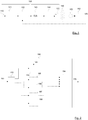
- Figure 1 is a generalized block diagram of an example arrangement for tuning a frequency-dependent attenuation stage 122 using a device 160 according to an example embodiment.
- an audio reproduction system 120 receives an input data signal 110 representing audio content to be played back by the audio reproduction system 120.
- the audio reproduction system 120 may for example be a consumer audio reproduction system comprised in a mobile device, or for example, a larger stationary audio reproduction system.
- the input data signal 110 may for example, be played from a file storage or from an external digital input. If the audio reproduction system 120 is comprised in a mobile device, the input data signal 110 may for example be transmitted from the device 160 to the audio reproduction system 120 via wireless communication.
- the audio reproduction system 120 supplies an output acoustic signal 140 in response to the input data signal 110.
- An acoustic transducer 150 for example, one or more microphones, records the acoustic output 140 from the audio reproduction system 120 and supplies data representing the recorded acoustic output to said device 160.
- the device 160 tunes a frequency-dependent attenuation stage 122 associated with the audio reproduction system 120 with the purpose of suppressing nonlinear distortion occurring in the audio reproduction system 120.
- the audio reproduction system 120 comprises a processing stage 121, the frequency-dependent attenuation stage 122, a digital-to-analog conversion stage 123, an amplification stage 124 and one or more loudspeakers 125 or headphones.
- the processing stage 121 may implement one or more signal processing tasks on the input data signal 110, for example, mixing of audio signals/channels represented by the input data signal 110 and/or equalization for correcting/balancing the magnitude response of the audio reproduction system's loudspeakers 125.
- the processed input data signal is then supplied to the frequency-dependent attenuation stage 122.
- the purpose of the frequency-dependent attenuation stage 122 is to control the amount of non-linear distortion created in the remaining stages of the audio reproduction system 120, for example, in the digital-to-analog conversion stage 123, the amplification stage 124 and the loudspeakers 125 or headphones.
- non-linear distortion occurring in the audio reproduction system 120 may be suppressed (e.g., by avoiding high amplitudes in frequency intervals sensitive/susceptible to non-linear distortion) and a tradeoff may be made between audible non-linear distortion and the overall loudness of the audio reproduction system 120.
- the frequency-dependent attenuation stage 122 may for example be implemented as a multi-band limiter in which different frequency bands are attenuated independently of each other, or as a timbre-preserving multi-band limiter, as described in US patent application publication no. 2013/0013096 A1 .
- the data signal output by the frequency-dependent attenuation stage 122 is then converted to analog form by the digital-to-analog conversion stage 123, and is amplified by the amplification stage 124, before it is fed to the loudspeakers 125 or headphones to be output as the output acoustic signal 140.
- the frequency-dependent attenuation stage 122 may be tuned based on information about the distortion behavior of the particular audio reproduction system 120. Such information may be obtained by example embodiments of the device 160, which will be described below with reference to Figure 2 .
- the audio reproduction system 120 depicted in Figure 1 serves as an example of an audio reproduction system associated with a frequency-dependent attenuation stage tunable by the device 160.
- a frequency-dependent attenuation stage tunable by the device 160 may be associated with an audio reproduction system comprising a different combination of processing stages, conversion stages and/or amplification stages, than the audio reproduction system 120 depicted in Figure 1 .
- a frequency-dependent attenuation stage tunable by the device 160 may be associated with an audio reproduction system without a digital-to-analog conversion stage 123, for example, because the input data signal 110 is played from an analogue input (and attenuation is performed by an analog frequency-dependent attenuation stage 122) or because the loudspeaker 125 is implemented as a digital loudspeaker using micro-electro-mechanical systems (MEMS).
- MEMS micro-electro-mechanical systems
- the audio reproduction system may not include a processing stage 121.
- FIG. 2 is a generalized block diagram of a device 160, according to example embodiments, for tuning the frequency-dependent attenuation stage 122 with the purpose of suppressing non-linear distortion occurring in the audio reproduction system 120 associated with the frequency-dependent attenuation stage 122.
- the device 160 comprises a receiving section 162 adapted to receive data 161 representing an output acoustic signal 140 recorded upon excitation of the audio reproduction system 120 by a predetermined input data signal 110.
- the device 160 may comprise an interface (not shown in Figure 2 ) adapted to provide the predetermined input audio signal 110 to the audio reproduction system 120, for example, via wired or wireless communication.
- the predetermined input audio signal 110 may be played by the audio reproduction system 120 from a file storage or may be received from some other device, and the device 160 may obtain knowledge about the predetermined input audio signal 110, for example, via separately received signaling and/or based on the received data 161.
- the acoustic transducer 150 shown in Figure 1 recording the data 161 representing the output acoustic signal 140, may for example be comprised in the device 160 or may be arranged separately from the device 160.
- the device 160 comprises a first distortion detection section 163 adapted to detect presence of non-linear distortion based on the received data 161 and to apply psycho-acoustic compensation to the detected non-linear distortion.
- the device 160 also comprises a control section 164 adapted to determine, based on the psycho-acoustically compensated non-linear distortion, control information 170 suitable for controlling the frequency-dependent attenuation stage 122. If, for example, the frequency-dependent attenuation stage 122 is a multi-band limiter, the control information 170 may indicate suitable thresholds to be applied by the multi-band limiter in respective frequency bands.
- the frequency-dependent attenuation stage 122 is a timbre-preserving multi-band limiter of the type described in US patent application publication no. 2013/0013096 A1 .
- the control information 170 may for example indicate suitable values for the fixed thresholds.
- Example operation of the first distortion detection section 163, according to the first example embodiment, will now be described with reference to Figures 3-5 .
- Other example embodiments of the device 160 depicted in Figure 2 will be described further below.
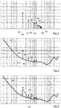
- Figure 3 schematically shows a double-logarithmic plot of an example spectrum of the output acoustic signal 140 upon excitation of a non-linearly distorting audio reproduction system 120 by an input data signal 110 corresponding to a single-frequency audio signal.
- the spectrum is illustrated in Figure 3 by plotting amplitude versus frequency.
- the output acoustic signal 140 comprises a first frequency component 301, also denoted by c 1 , localized substantially at the same frequency as the single-frequency audio signal, but also a number of non-linear distortion components 302-310, also denoted by c i , wherein i ⁇ 2, caused by non-linear distortion in the audio reproduction system 120 and located at other frequencies than the single-frequency audio signal.
- the example non-linear distortion components 302-310 depicted in Figure 3 are harmonic distortion components located at integer multiples of the frequency of the single-frequency audio signal.
- the first distortion detection section 163 may detect the non-linear distortion components 302-310 based on knowledge of the single-frequency audio signal represented by the predetermined input data signal 110. Rather than tuning the frequency-dependent attenuation stage 122 to suppress the creation of the detected non-linear distortion components 302-310 as such, the device 160 first takes into account how the non-linear distortion components 302-310 may be perceived by a listener.
- a psycho-acoustic compensation is initially applied to the different components, as described below with reference to Figures 4 and 5 .
- RMS ( c ) denotes the root mean square of a component c, i.e.
- RMS c 1 T 2 ⁇ T 1 ⁇ T 1 T 2 c t 2 dt , such that the power of the first frequency component 301 may be expressed as RMS ( c 1 ) 2 and the power of a non-linear distortion component may be expressed as RMS ( c i ) 2 .
- the spectrum shown in Figure 3 is compared to a frequency-dependent audibility threshold 320 indicating threshold amplitudes for different frequency components to be audible/perceptible by a representative (or average) human listener.
- the first distortion detection section 163 applies psycho-acoustic compensation by disregarding spectral content of the detected non-linear distortion below the frequency-dependent audibility threshold 320. For example, some of the non-linear distortion components 306-310 do not reach above the audibility threshold 320 and are disregarded.
- the first distortion detection section 163 may disregard a portion 301a of the first frequency component 301 below the audibility threshold 320 and may disregard respective portions 302a of the detected non-linear distortion components 302-5 below the audibility threshold 320, and may for example only consider the remaining portion 301b of the first frequency component 301 and the respective remaining portions 302b of the detected non-linear distortion components 302-305 in any remaining processing steps.
- Th ( f ( c 1 )) and Th ( f ( c i )) denote root mean square levels of the audibility threshold 320 at the frequencies f ( c 1 ) and f ( c i ) of the first frequency component 301 and the non-linear distortion components 302-310, respectively. It is to be noted that the sum in the above described power ratio only includes four non-linear distortion components 302-305, as the other non-linear distortion components 306-310 do not reach above the audibility threshold 320.
- non-linear distortion components 302-310 shown in Figures 3, 4 and 5 serve as an example, and that other example scenarios are envisaged in which any number of non-linear distortion components may be present in the acoustic output signal 140 and may be included in the above described power ratios.
- the frequency-dependent audibility threshold 320 may for example be calibrated based on a sound pressure level 169 estimated in connection with the recording of the output acoustic signal 140 represented by the received data 161, for example, by selecting an appropriate audibility threshold from a look-up table comprising audibility thresholds associated with different sound pressure levels.
- the sound pressure level 169 may be measured/estimated by a dedicated sound pressure level meter and may be received by the first distortion detection section 163.
- the acoustic transducer 150 may have been calibrated prior to the recording of the output acoustic signal 140, and the first distortion detection section 163 may be adapted to calibrate the frequency-dependent audibility threshold 320 based on known properties of the sound pressure level calibrated acoustic transducer 150.
- a masking threshold 330 has been included in the spectrum shown in Figure 4 , to indicate frequency masking as perceived by a an average human listener.
- the first frequency component 301 may have a masking effect on non-linear distortion (as well as other sound) in its spectral neighborhood.
- a non-linear distortion component 302-310 may have a masking effect on other non-linear distortion components in its spectral neighborhood.
- spectral content of the detected non-linear distortion below the masking threshold 330 may not be audible/perceptible to a listener and may for example be disregarded when tuning the frequency-dependent attenuation stage 122.
- the first distortion detection section 163 estimates the masking threshold 330 based on the first frequency component 301 and notes that the first non-linear distortion component 302 reaches above the masking threshold 330. It then updates the masking threshold 330 by also taking into account masking caused by the first non-linear distortion components 302 and notes that the second non-linear distortion component 303 reaches above the updated masking threshold 330. It then updates the masking threshold 330 by also taking into account masking caused by the second non-linear distortion component 303 and notes that the third non-linear distortion component 304 is below the updated masking threshold 330.
- the first distortion detection section 163 applies psycho-acoustic compensation by at least disregarding the third non-linear distortion component 304 as it is below the masking threshold 330. According to the second example embodiment, the first distortion detection section 163 then forms a power ratio similar to the power ratio described with reference to Figure 4 , but where at least the third non-linear distortion component 304 is disregarded. The control section 164 then determines the control parameters 170 also based on the determined power ratio.
- the frequency-dependent audibility threshold 320 and the masking threshold 330 described with reference to Figures 4 and 5 , respectively, may be calibrated or estimated based on known properties of representative human listeners. As the perception of sound may vary between different listeners, the frequency-dependent audibility threshold 320 and the masking threshold 330 may for example be set low enough to ensure that non-linear distortion which may be audible for example, to listeners with very sensitive hearing, is not disregarded. Alternatively, weighting may be applied to the detected non-linear distortion components 302-10 prior to forming the power ratio, the weights being based on how far below or above the frequency-dependent audibility threshold 320 and/or the masking threshold 330 the amplitudes of the respective non-linear distortion component 302-10 extend.
- the second harmonic component for example (i.e. the first non-linear distortion component 302 in Figure 3 ), is often reported to have a much more subtle effect on the sound than a higher-order harmonic component (for example, , the non-linear distortion component 310 in Figure 3 ).
- the first distortion detection section 163 may for example assign harmonic indices to the detected non-linear distortion components 302-10 and may apply weights to the non-linear distortion components 302-10 based on their respective harmonic indices, prior to forming a power ratio between the power of the first frequency component 301 and a sum of powers of the non-linear distortion components 302-10.
- An alternative to using the frequency-dependent audibility threshold 320 and/or the masking threshold 330, described with reference to Figures 4 and 5 is to evaluate the relative loudness of the first frequency component 301 and the detected non-linear distortion components 302-310, as perceived by a listener.
- applying psycho-acoustic compensation may include estimating a loudness of the first frequency component 301 and a combined loudness of the detected non-linear distortion components 302-310.
- the control section 164 may for example be adapted to determine the control information 170 also based on a difference between the estimated loudnesses. Estimating loudness may for example include employing weighting filters, such as A-, B- or C-weightings.
- the combined loudness of the non-linear distortion components may for example be estimated using a loudness summation scheme.
- the analysis of non-linear distortion described above with reference to Figures 3-5 may for example be repeated for different frequency bands by employing predetermine input data signals 110 from the respective frequency bands, and the control section 164 may for example determine the control information 170 based on information about distortion properties for the respective frequency bands.
- the device 160 depicted in Figure 2 may employ one or more distortion analysis methods in addition to the psycho-acoustic analysis methods described with reference to Figures 3-5 .
- a method for estimating the overall amount of non-linear distortion is to use relatively narrow-banded excitation signals at relatively low frequencies as the predetermined input data signal 110, to estimate high-frequency energy in the acoustic response 140, and to compare this to a pre-defined threshold. If there is non-negligible signal energy in the acoustic response 140 above the excitation frequency's bandwidth, this may be considered to be mainly caused by non-linear distortion.
- the device 160 may comprise a second distortion detection section 165 adapted to obtain knowledge of a frequency range covering the spectral content of the predetermined input data signal 110, and to detect non-linear distortion based on spectral content of the received data 161 above the frequency range. In such estimation of the overall non-linear distortion, it may not be necessary to determine locations of particular frequency components, but energy content in a given frequency region may be sufficient input data for making the estimation.
- a common distortion phenomenon especially in loudspeakers is the sudden increase of the amount of distortion when the excitation signal amplitude exceeds some limit value.
- the amount of distortion is typically relatively low for excitation signals below this limit, but becomes intolerably high for excitation signals above it. This can be considered to be a particular type of non-linear gain response.
- the device 160 may search for an abrupt spectral change in the acoustic response 140 indicating the presence of such a limit, and may estimate the input gain value corresponding to the limit.
- the device 160 may be adapted to receive data 161 recorded upon excitation of the audio reproduction system 120 by a sequence of predetermined input data signals 110, wherein consecutive predetermined input data signals 110 in the sequence correspond to increasingly amplified versions of a predetermined waveform.
- the device 160 may comprise a spectral composition analysis section 166 adapted to: monitor, based on the received data 161, the spectral composition of the output acoustic signals 140 of the audio reproduction system 120 resulting from excitation by the sequence of predetermined input data signals 110; detect an abrupt change in the monitored spectral composition; and determine an amplification value of the predetermined waveform corresponding to the detected abrupt change.
- a spectral composition analysis section 166 adapted to: monitor, based on the received data 161, the spectral composition of the output acoustic signals 140 of the audio reproduction system 120 resulting from excitation by the sequence of predetermined input data signals 110; detect an abrupt change in the monitored spectral composition; and determine an amplification value of the predetermined waveform corresponding to the detected abrupt change.
- the spectral composition analysis section 166 may be adapted to determine the spectral composition of the output acoustic signal 140 of the audio reproduction system 120 at discrete points in time corresponding to the respective elements of the sequence of predetermined input data signals 110, and may be adapted to detect abrupt changes between the spectral compositions determined at the respective points in time.
- the sequence of predetermined input data signals 110 may be received by the audio reproduction system 120 in the form of a the single sine signal with for example, continuously increasing amplitude, and the spectral composition of the output acoustic signal 140 of the audio reproduction system 120 may for example, be monitored continuously by the spectral composition analysis section 166, rather than being monitored/determined at discrete points in time corresponding to individual elements of the sequence of predetermined input data signals 110.
- a broadband excitation such as music
- a dual-channel fast Fourier transform based analysis method may be utilized to estimate the amount of non-linear distortion.
- measuring the coherence between input and output signals of the audio reproduction system 120 gives an estimate of linear dependency between the input and output signals.
- Non-linear distortion products, as well as noise, in the response lower the coherence value, while linear and time-invariant processes do not have such an effect.
- the inverse of the coherence value may be used as a measure of non-linear distortion in the case of wideband excitation signals.
- the device 160 may comprise a correlation analysis section 167 adapted to determine coherence between the predetermined input data signal 110 and the received data 140.
- the correlation analysis section 167 may be adapted to: determine a cross-correlation between the predetermined input data signal 110 and the received data 161; estimate a sample rate difference between the predetermined input data signal 110 and the received data 161 based on the determined cross-correlation; and determine the coherence based on a re-sampled version of the received data 161.
- DRC dynamic range control
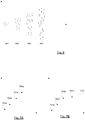
- the device 160 may be adapted to receive data 161 recorded upon excitation of the audio reproduction system 120 by input data signals 110 corresponding substantially to a single-frequency audio signal with increasing amplitude, as exemplified in Figure 6 by sine signals 601-604 with increasing amplitude.
- the device 160 may comprise a DRC detection section 168 adapted to: monitor, based on the received data 161, the amplitude of a frequency component in the output acoustic signal 140 from the audio reproduction system 120, the monitored frequency component being localized substantially at the same frequency as the single-frequency audio signal 601-604; and detect a saturation of the monitored amplitude, evidencing presence of DRC in the audio reproduction system 120.
- the amplitude of the single-frequency audio signal 601-604 is illustrated in Figure 7a by a sequence of amplitude values 701a-704a.
- the monitored amplitude for example, the amplitude of a frequency component in the output acoustic signal 140 localized substantially at the same frequency as the single-frequency audio signal 601-604, is exemplified in Figure 7b by a sequence of amplitude values 701b-704b.
- the input amplitude 701a-704a increases while the monitored output amplitude 701b-704b saturates at a level 710.
- the control section 164 may for example be adapted to determine, in response to the detection by the DRC detection section 168, control information 170 for causing the frequency-dependent attenuation stage 122 to suspend attenuation.
- the input data signals 110 corresponding substantially to a single-frequency audio signal with increasing amplitude, used as excitation to the audio reproduction system 120 may be provided in the form of a continuously growing sine signal (rather than sine signals 601-604 separated in time).
- the output amplitude may be monitored continuously by the DRC detection section 168, resulting in a curve, rather than the discrete amplitude values 701b-704b shown in Figure 7 .
- the device 160 may be adapted to receive data recorded upon excitation of the audio reproduction system 120 by a sequence of predetermined input data signals, wherein consecutive predetermined input data signals in the sequence correspond to increasingly amplified versions of a predetermined waveform.
- the predetermined waveform may for example be a single sine signal, as exemplified in Figure 6 , but may also be a more composite signal.
- the DRC detection section 168 may be adapted to monitor, based on the received data 161, the amplitude of the output acoustic signal 140 from the audio reproduction system 120 resulting from excitation of the audio reproduction system 120 by the sequence and detect a saturation of the monitored amplitude, evidencing presence of DRC in the audio reproduction system 120.
- the spectral composition of the predetermined waveform may preferably be known by the device 160, so that operation of a loudspeaker 125 outside its linear operation range may be detected based on the spectral composition of the output acoustic signal 140, and so that a saturation evidencing presence of DRC may be distinguished from saturation caused by operation of a loudspeaker outside its linear operation range.
- amplitudes obtainable in the acoustic output 140 there is typically an upper limit for the amplitudes obtainable in the acoustic output 140, for example, resulting from physical limitations in an amplification stage and/or in a loudspeaker, even without presence of DRC.
- a detected saturation evidencing presence of DRC in the audio reproduction system 120 is meant a saturation of the monitored amplitude at a level 710 below such an upper limit.
- the DRC detection section 168 may be adapted to estimate the signal to noise ratio (SNR) in the acoustic output 140, for example, by considering what remains after removing spectral content at the same frequency as the single-frequency audio signal along with any harmonics which may be present due to non-linear distortion. Detection of saturation, as described with reference to Figures 7a and 7b , in combination with a detection of a high SNR, may indicate presence of DRC in the audio reproduction system 120.
- SNR signal to noise ratio
- control section 164 may be adapted to determine, in response to the estimated SNR being above a predetermined threshold and the detection of saturation by the DRC detection section 168, control information 170 for causing the frequency-dependent attenuation stage 122 to suspend attenuation.
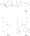
- Figure 10 is a flow chart of a method, according to an example embodiment, for detecting presence of DRC in the audio reproduction system 120.
- the method may for example be employed by the DRC detection section 168 of the tuning device 160 described with reference to Figures 1 and 2 , or by a separate DRC detection device, for example, arranged just like the tuning device 160 is arranged in Figure 1 , except that the DRC detection device may not be arranged to provide control information 170 to an attenuation stage 122.
- the method comprises receiving 1010 data recorded upon excitation of the audio reproduction system 120 by a sequence of predetermined input data signals, wherein consecutive predetermined input data signals in the sequence corresponds to increasingly amplified versions of a predetermined waveform and monitoring 1020, based on the received data, the amplitude of the output acoustic signal 140 from the audio reproduction system 120 resulting from excitation of the audio reproduction system 120 by the sequence.
- the method comprises detecting 1030 a saturation of the monitored amplitude, and, once a saturation is detected (indicated by Y in Figure 10 ), determining 1040 whether the detected saturation indicates/evidences presence of DRC.
- Determining 1040 whether a detected saturation indicates/evidences presence of DRC may for example include comparing the amplitude/energy/power level at which the saturation has been detected to physical limitations in an amplification stage and/or in a loudspeaker of the audio reproduction system 120 (as described above), and/or considering whether an estimated SNR is sufficiently high (as described above).
- the method returns (indicated by N in Figure 10 ) to receiving 1010 more data, corresponding to excitation of the audio reproduction system 120 by higher amplitude/energy/power levels, and monitoring 1020 the received data for detecting 1030 a saturation at higher amplitude/energy/power levels. If a detected saturation is determined 1040 to indicate/evidence presence of DRC (indicated by Y in Figure 10 ), further steps may be based on this decision, such as outputting/signaling 1050 detection of DRC, for example, to a control section 164 for determining control information 170, as described above with reference to Figure 2 .
- the method may return to receiving data 1010 representing an output acoustic signal 140 recorded upon excitation of the audio reproduction system 120 by input data signals 110 at different frequencies than previously employed as excitation.
- the detection of saturation for different excitation frequencies may be an even stronger indication of DRC in the audio reproduction system 120.
- a detected saturation is determined 1040 not to indicate/evidence presence of DRC (indicated by N in Figure 10 )
- further steps may be based on this decision, such as outputting/signaling 1060 that presence of DRC has not (yet) been detected.
- presence of DRC may be more easily detected in certain frequency bands.
- the method may for example return to receiving data 1010 representing an output acoustic signal 140 recorded upon excitation of the audio reproduction system 120 by input data signals 110 at different frequencies than previously employed as excitation.
- the device 160 comprises, a second distortion detection section 165, a spectral composition analysis section 166, a correlation analysis section 167, and/or a DRC detection section 168, in addition to the first distortion detection section 163.
- the device 160 comprises any combination of these sections and in which the control section 164 determines the control information 170 based on any combination of the information determined by the respective sections.
- the tuning of the frequency-dependent attenuation stage 122 may be improved and/or a more perceptually appealing balance may be achieved between audible non-linear distortion and overall loudness of the audio reproduction system 120.
- the control information 170 may be based on a weighted combination of analysis results obtained in the respective sections 163, 165, 166, 167, 168.
- the analysis performed by at least some of the first distortion detection section 163, the second distortion detection section 165, the spectral composition analysis section 166, the correlation analysis section 167, and the DRC detection section 168 may employ different types of predetermined input audio signals 110 as excitation to the audio reproduction system 120.
- a sequence of different types of predetermined input data signals 110 may be provided to the audio reproduction system 120 and the different sections may be adapted to perform their respective analyses after each other, for example, at different time points.
- the different sections illustrated in Figure 2 may for example be implemented as multiple functions of a single processor, or may for example be implemented in two or more separate physical units/components.
- the control section may be adapted to determine the control information by at least applying machine-learning based on a set of reference tunings of the frequency-dependent attenuation stage 122.
- the device 160 may comprise storage section (not shown in Figure 2 ) in which the reference tunings are stored.
- tuning of the frequency-dependent attenuation stage 122 using the arrangement depicted in Figure 1 may include varying the amplitude of the excitation signal 110 and analyzing the acoustic response 140.
- Figure 8 is a generalized block diagram of an alternative example arrangement for tuning the frequency-dependent attenuation stage 122, in which the frequency-dependent attenuation stage 122 may be bypassed 801, or its attenuation suspended, during tuning so as to analyze the non-linear distortion created in the audio reproduction system 120 without influence of the frequency-dependent attenuation stage 122.
- the frequency-dependent attenuation stage 122 is not a simple multi-band limiter, but has some functionality for varying the applied attenuation based for example, on the interaction between frequency regions/bands, such as the timbre-preserving multi-band limiter described in US patent application publication no. 2013/0013096 A1 . It may be beneficial to include the frequency-dependent attenuation stage 122 in the measurement process, as illustrated in Figure 1 , and to adjust its parameters while measuring the acoustic output 140. In this case, the excitation signal 110 may for example be a stationary signal as the amount of non-linear distortion created may be varied by adjusting, via the control information 170, the attenuation provided by the frequency-dependent attenuation stage 122.
- the device 160 may be adapted to receive data 161 recorded upon excitation of the audio reproduction system 120 by a constant input data signal 110 and the frequency-dependent attenuation stage 122 may be operable to attenuate the input data signal 110 based on the control information determined 170 by the control section of the device.
- the device 160 may be adapted to tune the frequency-dependent attenuation stage 122 by iteratively determining the control information 170 based on the received data 161.
- the frequency-dependent attenuation stage 122 may be beneficial to fully attenuate frequency regions which do not result in audible sound in the acoustic output 140 of the audio reproduction system 120, as doing so may prevent unnecessary power loss in the transducer and may also lead to additional distortion suppression.
- One approach to estimating whether a frequency can be radiated by the audio reproduction system 120 is to use a fixed-frequency sine signal as excitation 110, to estimate the cross-correlation between excitation 110 and acoustic response 140 for different lags between the excitation 110 and the acoustic response 140, and to check whether the maximum of the cross-correlation exceeds a given threshold.
- Figure 9 is a flow chart of a method, according to an example embodiment, for tuning the frequency-dependent attenuation stage 122 with the purpose of suppressing non-linear distortion occurring in the audio reproduction system 120 associated with the frequency-dependent attenuation stage 122.
- the method comprises receiving 901 data 161 representing an output acoustic signal 140 recorded upon excitation of the audio reproduction system 120 by a predetermined input data signal 110, detecting 902 presence of non-linear distortion based on the received data 161, applying 903 psycho-acoustic compensation to the detected non-linear distortion and, based on the psycho-acoustically compensated non-linear distortion, determining 904 control information 170 suitable for controlling the frequency-dependent attenuation stage 122.
- the devices and methods disclosed hereinabove may be implemented as software, firmware, hardware or a combination thereof.
- the division of tasks between functional units referred to in the above description does not necessarily correspond to the division into physical units; to the contrary, one physical component may have multiple functionalities, and one task may be carried out by several physical components in cooperation.
- Certain components or all components may be implemented as software executed by a digital signal processor or microprocessor, or be implemented as hardware or as an application-specific integrated circuit.
- Such software may be distributed on computer readable media, which may comprise computer storage media (or non-transitory media) and communication media (or transitory media).
- Computer storage media includes both volatile and nonvolatile, removable and non-removable media implemented in any method or technology for storage of information such as computer readable instructions, data structures, program modules or other data.
- Computer storage media includes, but is not limited to, RAM, ROM, EEPROM, flash memory or other memory technology, CD-ROM, digital versatile disks (DVD) or other optical disk storage, magnetic cassettes, magnetic tape, magnetic disk storage or other magnetic storage devices, or any other medium which can be used to store the desired information and which can be accessed by a computer.
- communication media typically embodies computer readable instructions, data structures, program modules or other data in a modulated data signal such as a carrier wave or other transport mechanism and includes any information delivery media.
Landscapes
- Engineering & Computer Science (AREA)
- Physics & Mathematics (AREA)
- Acoustics & Sound (AREA)
- Signal Processing (AREA)
- Computational Linguistics (AREA)
- Quality & Reliability (AREA)
- Health & Medical Sciences (AREA)
- Audiology, Speech & Language Pathology (AREA)
- Human Computer Interaction (AREA)
- Multimedia (AREA)
- Circuit For Audible Band Transducer (AREA)
- Tone Control, Compression And Expansion, Limiting Amplitude (AREA)
Claims (15)
- Dispositif (160) pour régler un étage d'atténuation dépendant de la fréquence (122) dans le but de supprimer une distorsion non linéaire se produisant dans un système de reproduction audio (120) associé à l'étage d'atténuation dépendant de la fréquence, dans lequel l'étage d'atténuation dépendant de la fréquence est un compresseur multibande, le système de reproduction audio étant agencé pour fournir un signal acoustique de sortie (140) en réponse à un signal de données d'entrée (110), le dispositif comprenant :une section de réception (162) adaptée pour recevoir des données (161) représentant un signal acoustique de sortie enregistré lors de l'excitation du système de reproduction audio par un signal de données d'entrée prédéterminé ;une première section de détection de distorsion (163) adaptée pour détecter une présence de distorsion non linéaire sur la base des données reçues et pour appliquer une compensation psychoacoustique à la distorsion non linéaire détectée ; etune section de commande (164) adaptée pour déterminer, sur la base de la distorsion non linéaire compensée psychoacoustiquement, des informations de commande (170) pour commander ledit compresseur multibande pour supprimer la distorsion non linéaire se produisant dans ledit système de reproduction audio.
- Dispositif selon la revendication 1, dans lequel les informations de commande indiquent des seuils à appliquer par le compresseur multibande dans des bandes de fréquence respectives.
- Dispositif selon l'une quelconque des revendications précédentes, dans lequel la première section de détection de distorsion est adaptée pour appliquer une compensation psychoacoustique au moins en ne tenant pas compte d'un contenu spectral de la distorsion non linéaire détectée en dessous d'un seuil d'audibilité dépendant de la fréquence (320), dans lequel la première section de détection de distorsion est adaptée pour étalonner le seuil d'audibilité dépendant de la fréquence sur la base d'un niveau de pression sonore (169) estimé en rapport avec l'enregistrement du signal acoustique de sortie représenté par les données reçues.
- Dispositif selon l'une quelconque des revendications précédentes, dans lequel la première section de détection de distorsion est adaptée pour appliquer une compensation psychoacoustique au moins en :obtenant une connaissance d'un premier composant de fréquence du signal de données d'entrée prédéterminé ;estimant, sur la base du premier composant de fréquence, un seuil de masquage (330) pour un voisinage du premier composant de fréquence ; etne tenant pas compte d'un contenu spectral de la distorsion non linéaire détectée en dessous du seuil de masquage.
- Dispositif selon l'une quelconque des revendications précédentes, dans lequel la première section de détection de distorsion est adaptée pour :obtenir une connaissance d'un premier composant de fréquence du signal de données d'entrée prédéterminé ; etdétecter, sur la base des données reçues, des composants de distorsion non linéaire (302-310) correspondant au premier composant de fréquence.
- Dispositif selon la revendication 5, dans lequel la première section de détection de distorsion est adaptée pour déterminer un rapport de puissance entre la puissance du tel contenu spectral (301) des données reçues qui est situé sensiblement à la même fréquence que le premier composant de fréquence et une somme de puissances desdits composants de distorsion non linéaire, et dans lequel la section de commande est adaptée pour déterminer les informations de commande également sur la base dudit rapport de puissance.
- Dispositif selon la revendication 6, dans lequel la première section de détection de distorsion est adaptée pour appliquer une compensation psychoacoustique au moins en normalisant, avant de former ledit rapport de puissance, la puissance dudit contenu spectral des données reçues et les puissances desdits composants de distorsion non linéaire, par rapport à un seuil d'audibilité dépendant de la fréquence.
- Dispositif selon l'une quelconque des revendications 5 à 7, dans lequel la première section de détection de distorsion est adaptée pour appliquer une compensation psychoacoustique au moins en :attribuant des indices harmoniques auxdits composants de distorsion non linéaire ; etappliquant des poids auxdits composants de distorsion non linéaire sur la base desdits indices harmoniques.
- Dispositif selon la revendication 5, dans lequel la première section de détection de distorsion est adaptée pour appliquer une compensation psychoacoustique au moins en estimant une intensité sonore dudit contenu spectral des données reçues et une intensité sonore combinée desdits composants de distorsion non linéaire, et dans lequel la section de commande est adaptée pour déterminer les informations de commande également sur la base d'une différence entre les intensités sonores estimées.
- Dispositif selon l'une quelconque des revendications précédentes, comprenant une seconde section de détection de distorsion (165) adaptée pour :obtenir une connaissance d'une gamme de fréquences couvrant le contenu spectral du signal de données d'entrée prédéterminé ; etdétecter une distorsion non linéaire sur la base d'un contenu spectral des données reçues au-dessus de ladite gamme de fréquences,dans lequel la section de commande est adaptée pour déterminer les informations de commande également sur la base de la distorsion non linéaire détectée par la seconde section de détection de distorsion.
- Dispositif selon l'une quelconque des revendications précédentes, adapté pour recevoir des données enregistrées lors de l'excitation du système de reproduction audio par une séquence de signaux de données d'entrée prédéterminés, des signaux de données d'entrée prédéterminés consécutifs dans ladite séquence correspondant à des versions de plus en plus amplifiées d'une forme d'onde prédéterminée, le dispositif comprenant une section d'analyse de composition spectrale (166) adaptée pour :surveiller, sur la base des données reçues, la composition spectrale des signaux acoustiques de sortie du système de reproduction audio résultant de l'excitation par ladite séquence de signaux de données d'entrée prédéterminés ;détecter un changement brusque dans la composition spectrale surveillée ; etdéterminer une valeur d'amplification de ladite forme d'onde prédéterminée correspondant au changement brusque détecté, dans lequel la section de commande est adaptée pour déterminer les informations de commande également sur la base de la valeur d'amplification déterminée par la section d'analyse de composition spectrale,ou le dispositif comprenant une section de détection de commande de plage dynamique, DRC, (168) adaptée pour :surveiller, sur la base des données reçues, l'amplitude du signal acoustique de sortie depuis le système de reproduction audio résultant de l'excitation du système de reproduction audio par ladite séquence ; etdétecter une saturation de l'amplitude surveillée, attestant la présence de DRC dans le système de reproduction audio, dans lequel la section de commande est adaptée pour déterminer les informations de commande également sur la base d'un résultat de la détection par la section de détection DRC.
- Dispositif selon la revendication 11, dans lequel la section de commande est adaptée pour déterminer, en réponse à la détection par la section de détection DRC, des informations de commande pour amener l'étage d'atténuation dépendant de la fréquence à suspendre l'atténuation.
- Dispositif selon l'une quelconque des revendications précédentes, comprenant une section d'analyse de corrélation (167) adaptée pour déterminer une cohérence entre le signal de données d'entrée prédéterminé et les données reçues, dans lequel la section de commande est adaptée pour déterminer les informations de commande également sur la base de valeurs de la cohérence déterminée par la section d'analyse de cohérence, et dans lequel la section d'analyse de corrélation est adaptée pour :déterminer une corrélation croisée entre le signal de données d'entrée prédéterminé et les données reçues ;estimer une différence de fréquence d'échantillonnage entre le signal de données d'entrée prédéterminé et les données reçues sur la base de la corrélation croisée déterminée ; etdéterminer ladite cohérence sur la base d'une version rééchantillonnée des données reçues.
- Procédé pour régler un étage d'atténuation dépendant de la fréquence (122) dans le but de supprimer une distorsion non linéaire se produisant dans un système de reproduction audio (120) associé à l'étage d'atténuation dépendant de la fréquence, dans lequel l'étage d'atténuation dépendant de la fréquence est un compresseur multibande, le système de reproduction audio étant agencé pour fournir un signal acoustique de sortie (140) en réponse à un signal de données d'entrée (110), le procédé comprenant les étapes consistant à :recevoir (901) des données (161) représentant un signal acoustique de sortie enregistré lors de l'excitation du système de reproduction audio par un signal de données d'entrée prédéterminé ;détecter (902) une présence de distorsion non linéaire sur la base des données reçues ;appliquer (903) une compensation psychoacoustique à la distorsion non linéaire détectée ; etsur la base de la distorsion non linéaire compensée psychoacoustiquement, déterminer (904) des informations de commande (170) pour commander ledit compresseur multibande pour supprimer la distorsion non linéaire se produisant dans ledit système de reproduction audio.
- Produit de programme informatique comprenant un support lisible par ordinateur avec des instructions pour amener un ordinateur à exécuter le procédé selon la revendication 14.
Applications Claiming Priority (2)
| Application Number | Priority Date | Filing Date | Title |
|---|---|---|---|
| US201461941414P | 2014-02-18 | 2014-02-18 | |
| PCT/EP2015/053372 WO2015124598A1 (fr) | 2014-02-18 | 2015-02-18 | Dispositif et procédé pour régler un étage d'atténuation dépendant de la fréquence |
Publications (2)
| Publication Number | Publication Date |
|---|---|
| EP3108669A1 EP3108669A1 (fr) | 2016-12-28 |
| EP3108669B1 true EP3108669B1 (fr) | 2020-04-08 |
Family
ID=52627173
Family Applications (1)
| Application Number | Title | Priority Date | Filing Date |
|---|---|---|---|
| EP15707892.4A Active EP3108669B1 (fr) | 2014-02-18 | 2015-02-18 | Dispositif et procédé pour régler un étage d'atténuation dépendant de la fréquence |
Country Status (5)
| Country | Link |
|---|---|
| US (1) | US10283137B2 (fr) |
| EP (1) | EP3108669B1 (fr) |
| JP (2) | JP6420353B2 (fr) |
| CN (2) | CN106105262B (fr) |
| WO (1) | WO2015124598A1 (fr) |
Cited By (2)
| Publication number | Priority date | Publication date | Assignee | Title |
|---|---|---|---|---|
| US11812239B2 (en) | 2019-04-30 | 2023-11-07 | Waves Audio Ltd. | Dynamic reduction of loudspeaker distortion based on psychoacoustic masking |
| EP4385010A4 (fr) * | 2021-08-10 | 2025-05-14 | VoiceAge Corporation | Procédé et dispositif de limitation de distorsion de synthèse de sortie dans un codec sonore |
Families Citing this family (17)
| Publication number | Priority date | Publication date | Assignee | Title |
|---|---|---|---|---|
| US10936277B2 (en) | 2015-06-29 | 2021-03-02 | Audeara Pty Ltd. | Calibration method for customizable personal sound delivery system |
| US10142731B2 (en) | 2016-03-30 | 2018-11-27 | Dolby Laboratories Licensing Corporation | Dynamic suppression of non-linear distortion |
| WO2019070328A1 (fr) * | 2017-10-04 | 2019-04-11 | Google Llc | Procédés et systèmes permettant d'égaliser automatiquement une sortie audio sur la base des caractéristiques de la pièce |
| US10333482B1 (en) * | 2018-02-04 | 2019-06-25 | Omnivision Technologies, Inc. | Dynamic output level correction by monitoring speaker distortion to minimize distortion |
| EP3579582B1 (fr) * | 2018-06-06 | 2023-11-15 | Dolby Laboratories Licensing Corporation | Caractérisation automatique de la distorsion perçue d'un transducteur |
| CN110753295B (zh) * | 2018-07-23 | 2023-04-18 | 奥德拉私人有限公司 | 可定制个人声音传送系统的校准方法 |
| JP7019099B2 (ja) | 2018-09-28 | 2022-02-14 | ドルビー ラボラトリーズ ライセンシング コーポレイション | シーン切り換え解析器にガイドされる歪み可聴性モデルに基づく動的閾値を有する歪み低減マルチバンド・コンプレッサー |
| HRP20230332T1 (hr) * | 2019-02-13 | 2023-05-26 | Mozzaik.Io D.O.O. | Metoda i uređaj za obradu audio signala |
| HRP20190292A2 (hr) * | 2019-02-13 | 2020-08-21 | Mozzaik.Io D.O.O. | Metoda i uređaj za obradu audio signala |
| US10904663B2 (en) | 2019-04-25 | 2021-01-26 | Samsung Electronics Co., Ltd. | Reluctance force compensation for loudspeaker control |
| CN110809214B (zh) * | 2019-11-21 | 2021-01-08 | Oppo广东移动通信有限公司 | 音频播放方法、音频播放装置及终端设备 |
| CN112887878B (zh) * | 2019-11-29 | 2025-09-19 | 哈曼国际工业有限公司 | 避免削波失真或增加有源扬声器最大声级的压限系统和方法 |
| US11817114B2 (en) * | 2019-12-09 | 2023-11-14 | Dolby Laboratories Licensing Corporation | Content and environmentally aware environmental noise compensation |
| CN115668984A (zh) * | 2020-05-27 | 2023-01-31 | 杜比实验室特许公司 | 音频扬声器的瞬态多音调测试信号和方法 |
| CN118486319B (zh) * | 2024-05-31 | 2025-03-07 | 深圳市欧睿驰科技有限公司 | 一种基于数据分析的降噪功能音频数据处理系统 |
| CN119007736A (zh) * | 2024-07-22 | 2024-11-22 | 深圳市冠旭电子股份有限公司 | 一种音频压缩方法及装置 |
| US12395783B1 (en) * | 2024-08-23 | 2025-08-19 | Fourier Sound, Inc. | Method of operating a sound system to create a functionally massless driver |
Family Cites Families (53)
| Publication number | Priority date | Publication date | Assignee | Title |
|---|---|---|---|---|
| US3940715A (en) | 1974-09-25 | 1976-02-24 | Sound Technology, Inc. | Distortion measurement system |
| FR2301133A1 (fr) | 1975-02-14 | 1976-09-10 | Thomson Csf | Dispo |
| JP2567099B2 (ja) * | 1989-06-16 | 1996-12-25 | パイオニア株式会社 | 音響伝達特性制御装置 |
| JPH03106199A (ja) * | 1989-09-19 | 1991-05-02 | Onkyo Corp | 再生音制御装置 |
| JPH07122953A (ja) * | 1993-10-22 | 1995-05-12 | Matsushita Electric Ind Co Ltd | 信号レベル圧縮装置 |
| DE4336608C2 (de) * | 1993-10-27 | 1997-02-06 | Klippel Wolfgang | Schaltungsanordnung zum Schutz elektrodynamischer Lautsprecher gegen mechanische Überlastung durch hohe Schwingspulenauslenkung |
| EP0730798A1 (fr) | 1993-11-25 | 1996-09-11 | BRITISH TELECOMMUNICATIONS public limited company | Procede et appareil permettant de tester un equipement de telecommunications |
| US5850453A (en) | 1995-07-28 | 1998-12-15 | Srs Labs, Inc. | Acoustic correction apparatus |
| US6108431A (en) | 1996-05-01 | 2000-08-22 | Phonak Ag | Loudness limiter |
| DE19640132B4 (de) | 1996-09-28 | 2015-06-03 | Volkswagen Ag | Verfahren zur automatischen Begrenzung von Verzerrungen an Audio-Geräten und Schaltungsanordnung zur Durchführung des Verfahrens |
| US6185300B1 (en) | 1996-12-31 | 2001-02-06 | Ericsson Inc. | Echo canceler for use in communications system |
| US6570985B1 (en) | 1998-01-09 | 2003-05-27 | Ericsson Inc. | Echo canceler adaptive filter optimization |
| DE69920273T2 (de) | 1998-11-12 | 2005-09-22 | Broadcom Corp., Irvine | Integrierte tunerarchitektur |
| EP1811660B1 (fr) | 1999-03-30 | 2013-10-09 | Qualcomm Incorporated | Procédé et dispositif pour contrôler automatiquement le gain d'un haut-parleur dans un téléphone mobile |
| CN1516493A (zh) * | 2003-01-10 | 2004-07-28 | 深圳市中兴通讯股份有限公司上海第二 | 一种功率放大器线性化方法和线性功率放大器装置 |
| US8199933B2 (en) | 2004-10-26 | 2012-06-12 | Dolby Laboratories Licensing Corporation | Calculating and adjusting the perceived loudness and/or the perceived spectral balance of an audio signal |
| MX2007005027A (es) | 2004-10-26 | 2007-06-19 | Dolby Lab Licensing Corp | Calculo y ajuste de la sonoridad percibida y/o el balance espectral percibido de una senal de audio. |
| US7564979B2 (en) | 2005-01-08 | 2009-07-21 | Robert Swartz | Listener specific audio reproduction system |
| CN101053152B (zh) | 2005-07-29 | 2010-12-29 | 哈曼国际工业有限公司 | 自动音频调谐系统及方法 |
| FR2890280A1 (fr) * | 2005-08-26 | 2007-03-02 | Elsi Ingenierie Sarl | Procede de filtrage numerique et de compensation pour lineariser la courbe de reponse d'une enceinte acoustique et moyens mis en oeuvre |
| JP2007081815A (ja) * | 2005-09-14 | 2007-03-29 | Matsushita Electric Ind Co Ltd | スピーカ装置 |
| JP4853176B2 (ja) * | 2005-09-28 | 2012-01-11 | ヤマハ株式会社 | D級増幅器 |
| FI122089B (fi) * | 2006-03-28 | 2011-08-15 | Genelec Oy | Kalibrointimenetelmä ja -laitteisto äänentoistojärjestelmässä |
| BRPI0709877B1 (pt) | 2006-04-04 | 2019-12-31 | Dolby Laboratories Licensing Corp | método e aparelho para controlar uma característica de intensidade acústica particular de um sinal de áudio |
| US7593535B2 (en) * | 2006-08-01 | 2009-09-22 | Dts, Inc. | Neural network filtering techniques for compensating linear and non-linear distortion of an audio transducer |
| US8311590B2 (en) * | 2006-12-05 | 2012-11-13 | Hewlett-Packard Development Company, L.P. | System and method for improved loudspeaker functionality |
| EP1986466B1 (fr) | 2007-04-25 | 2018-08-08 | Harman Becker Automotive Systems GmbH | Procédé et appareil pour le réglage du son |
| US7742746B2 (en) | 2007-04-30 | 2010-06-22 | Qualcomm Incorporated | Automatic volume and dynamic range adjustment for mobile audio devices |
| JP2010122617A (ja) * | 2008-11-21 | 2010-06-03 | Yamaha Corp | ノイズゲート、及び収音装置 |
| JP5136378B2 (ja) * | 2008-12-09 | 2013-02-06 | 富士通株式会社 | 音響処理方法 |
| EP2401872A4 (fr) | 2009-02-25 | 2012-05-23 | Conexant Systems Inc | Système et procédé de réduction de distorsion de haut-parleur |
| EP2535891B1 (fr) * | 2009-04-28 | 2013-07-31 | Bose Corporation | Réalisation de registres dans un circuit de réduction active de bruit |
| US8532310B2 (en) * | 2010-03-30 | 2013-09-10 | Bose Corporation | Frequency-dependent ANR reference sound compression |
| US9101299B2 (en) | 2009-07-23 | 2015-08-11 | Dean Robert Gary Anderson As Trustee Of The D/L Anderson Family Trust | Hearing aids configured for directional acoustic fitting |
| US8879745B2 (en) | 2009-07-23 | 2014-11-04 | Dean Robert Gary Anderson As Trustee Of The D/L Anderson Family Trust | Method of deriving individualized gain compensation curves for hearing aid fitting |
| US8538042B2 (en) | 2009-08-11 | 2013-09-17 | Dts Llc | System for increasing perceived loudness of speakers |
| KR101681798B1 (ko) * | 2009-08-11 | 2016-12-01 | 디티에스 엘엘씨 | 스피커의 인지성 소리 강도를 증가시키는 시스템 |
| CN104242853B (zh) | 2010-03-18 | 2017-05-17 | 杜比实验室特许公司 | 用于具有音质保护的失真减少多频带压缩器的技术 |
| US9130527B2 (en) * | 2010-08-18 | 2015-09-08 | Dolby Laboratories Licensing Corporation | Method and system for controlling distortion in a critical frequency band of an audio signal |
| US8509450B2 (en) | 2010-08-23 | 2013-08-13 | Cambridge Silicon Radio Limited | Dynamic audibility enhancement |
| JP4892095B1 (ja) * | 2010-11-26 | 2012-03-07 | 株式会社東芝 | 音響補正装置、及び音響補正方法 |
| JP5480842B2 (ja) * | 2011-04-25 | 2014-04-23 | 日本電信電話株式会社 | クリップノイズ検出装置、クリップノイズ検出方法、プログラム |
| US8873763B2 (en) | 2011-06-29 | 2014-10-28 | Wing Hon Tsang | Perception enhancement for low-frequency sound components |
| US8965774B2 (en) * | 2011-08-23 | 2015-02-24 | Apple Inc. | Automatic detection of audio compression parameters |
| WO2013049125A1 (fr) | 2011-09-26 | 2013-04-04 | Actiwave Ab | Système de traitement et d'amélioration de l'audio |
| EP2575375B1 (fr) * | 2011-09-28 | 2015-03-18 | Nxp B.V. | Contrôle de la sortie d'un haut-parleur |
| JP5841405B2 (ja) * | 2011-11-02 | 2016-01-13 | クラリオン株式会社 | ダイナミックレンジ拡張装置 |
| WO2013075848A1 (fr) * | 2011-11-21 | 2013-05-30 | Jacoti Bvba | Système et procédé pour la détection de niveau de signal |
| US9654866B2 (en) * | 2012-01-27 | 2017-05-16 | Conexant Systems, Inc. | System and method for dynamic range compensation of distortion |
| EP2632173B1 (fr) * | 2012-02-22 | 2015-06-03 | Harman Becker Automotive Systems GmbH | Protection de surcharge de haut-parleur |
| CN103325380B (zh) * | 2012-03-23 | 2017-09-12 | 杜比实验室特许公司 | 用于信号增强的增益后处理 |
| US9173020B2 (en) * | 2012-03-27 | 2015-10-27 | Htc Corporation | Control method of sound producing, sound producing apparatus, and portable apparatus |
| JP6304643B2 (ja) * | 2013-05-02 | 2018-04-04 | 学校法人 工学院大学 | スピーカーの非線形歪低減装置、方法、及びプログラム |
-
2015
- 2015-02-18 EP EP15707892.4A patent/EP3108669B1/fr active Active
- 2015-02-18 JP JP2016552893A patent/JP6420353B2/ja active Active
- 2015-02-18 CN CN201580008920.0A patent/CN106105262B/zh active Active
- 2015-02-18 WO PCT/EP2015/053372 patent/WO2015124598A1/fr not_active Ceased
- 2015-02-18 CN CN201910654361.0A patent/CN110381421B/zh active Active
- 2015-02-18 US US15/119,687 patent/US10283137B2/en active Active
-
2018
- 2018-10-11 JP JP2018192701A patent/JP6711881B2/ja active Active
Non-Patent Citations (1)
| Title |
|---|
| None * |
Cited By (2)
| Publication number | Priority date | Publication date | Assignee | Title |
|---|---|---|---|---|
| US11812239B2 (en) | 2019-04-30 | 2023-11-07 | Waves Audio Ltd. | Dynamic reduction of loudspeaker distortion based on psychoacoustic masking |
| EP4385010A4 (fr) * | 2021-08-10 | 2025-05-14 | VoiceAge Corporation | Procédé et dispositif de limitation de distorsion de synthèse de sortie dans un codec sonore |
Also Published As
| Publication number | Publication date |
|---|---|
| JP6711881B2 (ja) | 2020-06-17 |
| EP3108669A1 (fr) | 2016-12-28 |
| CN110381421B (zh) | 2021-05-25 |
| JP2017506464A (ja) | 2017-03-02 |
| JP2019033522A (ja) | 2019-02-28 |
| US10283137B2 (en) | 2019-05-07 |
| CN110381421A (zh) | 2019-10-25 |
| US20170061982A1 (en) | 2017-03-02 |
| WO2015124598A1 (fr) | 2015-08-27 |
| CN106105262B (zh) | 2019-08-16 |
| CN106105262A (zh) | 2016-11-09 |
| HK1231660A1 (en) | 2017-12-22 |
| JP6420353B2 (ja) | 2018-11-07 |
Similar Documents
| Publication | Publication Date | Title |
|---|---|---|
| EP3108669B1 (fr) | Dispositif et procédé pour régler un étage d'atténuation dépendant de la fréquence | |
| JP5602309B2 (ja) | オーディオ信号の臨界周波数帯域における歪みを制御する方法とシステム | |
| US8194889B2 (en) | Hybrid digital/analog loudness-compensating volume control | |
| US9391579B2 (en) | Dynamic compensation of audio signals for improved perceived spectral imbalances | |
| EP1629463B1 (fr) | PROCEDE, APPAREIL ET PROGRAMME INFORMATIQUE POUR LE CALCUL ET LE REGLAGE DE LA FORCE SONORE PERçUE D'UN SIGNAL SONORE | |
| KR101732208B1 (ko) | 오디오 녹음의 적응적 동적 범위 강화 | |
| US8634578B2 (en) | Multiband dynamics compressor with spectral balance compensation | |
| US8868414B2 (en) | Audio signal processing device with enhancement of low-pitch register of audio signal | |
| US20100128882A1 (en) | Audio signal processing device and audio signal processing method | |
| US20190075395A1 (en) | Speaker Distortion Reduction | |
| CN103580630A (zh) | 自动响度控制 | |
| US11950064B2 (en) | Method for audio rendering by an apparatus | |
| US10805723B2 (en) | Automatic characterization of perceived transducer distortion | |
| HK1231660B (en) | Device and method for tuning a frequency-dependent attenuation stage | |
| EP1835487B1 (fr) | Procédé, appareil et programme informatique pour calculer et régler le volume perçu d'un signal audio | |
| HK1105711B (en) | Method, apparatus and computer program for calculating and adjusting the perceived loudness of an audio signal | |
| HK1187741B (en) | Dynamic compensation of audio signals for improved perceived spectral imbalances |
Legal Events
| Date | Code | Title | Description |
|---|---|---|---|
| PUAI | Public reference made under article 153(3) epc to a published international application that has entered the european phase |
Free format text: ORIGINAL CODE: 0009012 |
|
| STAA | Information on the status of an ep patent application or granted ep patent |
Free format text: STATUS: REQUEST FOR EXAMINATION WAS MADE |
|
| 17P | Request for examination filed |
Effective date: 20160919 |
|
| AK | Designated contracting states |
Kind code of ref document: A1 Designated state(s): AL AT BE BG CH CY CZ DE DK EE ES FI FR GB GR HR HU IE IS IT LI LT LU LV MC MK MT NL NO PL PT RO RS SE SI SK SM TR |
|
| AX | Request for extension of the european patent |
Extension state: BA ME |
|
| DAX | Request for extension of the european patent (deleted) | ||
| REG | Reference to a national code |
Ref country code: HK Ref legal event code: DE Ref document number: 1231660 Country of ref document: HK |
|
| GRAP | Despatch of communication of intention to grant a patent |
Free format text: ORIGINAL CODE: EPIDOSNIGR1 |
|
| STAA | Information on the status of an ep patent application or granted ep patent |
Free format text: STATUS: GRANT OF PATENT IS INTENDED |
|
| INTG | Intention to grant announced |
Effective date: 20191031 |
|
| GRAS | Grant fee paid |
Free format text: ORIGINAL CODE: EPIDOSNIGR3 |
|
| GRAA | (expected) grant |
Free format text: ORIGINAL CODE: 0009210 |
|
| STAA | Information on the status of an ep patent application or granted ep patent |
Free format text: STATUS: THE PATENT HAS BEEN GRANTED |
|
| RAP1 | Party data changed (applicant data changed or rights of an application transferred) |
Owner name: DOLBY LABORATORIES LICENSING CORPORATION Owner name: DOLBY INTERNATIONAL AB |
|
| AK | Designated contracting states |
Kind code of ref document: B1 Designated state(s): AL AT BE BG CH CY CZ DE DK EE ES FI FR GB GR HR HU IE IS IT LI LT LU LV MC MK MT NL NO PL PT RO RS SE SI SK SM TR |
|
| REG | Reference to a national code |
Ref country code: AT Ref legal event code: REF Ref document number: 1255992 Country of ref document: AT Kind code of ref document: T Effective date: 20200415 Ref country code: CH Ref legal event code: EP |
|
| REG | Reference to a national code |
Ref country code: DE Ref legal event code: R096 Ref document number: 602015050215 Country of ref document: DE |
|
| REG | Reference to a national code |
Ref country code: IE Ref legal event code: FG4D |
|
| REG | Reference to a national code |
Ref country code: NL Ref legal event code: MP Effective date: 20200408 |
|
| REG | Reference to a national code |
Ref country code: LT Ref legal event code: MG4D |
|
| PG25 | Lapsed in a contracting state [announced via postgrant information from national office to epo] |
Ref country code: LT Free format text: LAPSE BECAUSE OF FAILURE TO SUBMIT A TRANSLATION OF THE DESCRIPTION OR TO PAY THE FEE WITHIN THE PRESCRIBED TIME-LIMIT Effective date: 20200408 Ref country code: FI Free format text: LAPSE BECAUSE OF FAILURE TO SUBMIT A TRANSLATION OF THE DESCRIPTION OR TO PAY THE FEE WITHIN THE PRESCRIBED TIME-LIMIT Effective date: 20200408 Ref country code: NL Free format text: LAPSE BECAUSE OF FAILURE TO SUBMIT A TRANSLATION OF THE DESCRIPTION OR TO PAY THE FEE WITHIN THE PRESCRIBED TIME-LIMIT Effective date: 20200408 Ref country code: GR Free format text: LAPSE BECAUSE OF FAILURE TO SUBMIT A TRANSLATION OF THE DESCRIPTION OR TO PAY THE FEE WITHIN THE PRESCRIBED TIME-LIMIT Effective date: 20200709 Ref country code: IS Free format text: LAPSE BECAUSE OF FAILURE TO SUBMIT A TRANSLATION OF THE DESCRIPTION OR TO PAY THE FEE WITHIN THE PRESCRIBED TIME-LIMIT Effective date: 20200808 Ref country code: SE Free format text: LAPSE BECAUSE OF FAILURE TO SUBMIT A TRANSLATION OF THE DESCRIPTION OR TO PAY THE FEE WITHIN THE PRESCRIBED TIME-LIMIT Effective date: 20200408 Ref country code: PT Free format text: LAPSE BECAUSE OF FAILURE TO SUBMIT A TRANSLATION OF THE DESCRIPTION OR TO PAY THE FEE WITHIN THE PRESCRIBED TIME-LIMIT Effective date: 20200817 Ref country code: NO Free format text: LAPSE BECAUSE OF FAILURE TO SUBMIT A TRANSLATION OF THE DESCRIPTION OR TO PAY THE FEE WITHIN THE PRESCRIBED TIME-LIMIT Effective date: 20200708 |
|
| REG | Reference to a national code |
Ref country code: AT Ref legal event code: MK05 Ref document number: 1255992 Country of ref document: AT Kind code of ref document: T Effective date: 20200408 |
|
| PG25 | Lapsed in a contracting state [announced via postgrant information from national office to epo] |
Ref country code: RS Free format text: LAPSE BECAUSE OF FAILURE TO SUBMIT A TRANSLATION OF THE DESCRIPTION OR TO PAY THE FEE WITHIN THE PRESCRIBED TIME-LIMIT Effective date: 20200408 Ref country code: LV Free format text: LAPSE BECAUSE OF FAILURE TO SUBMIT A TRANSLATION OF THE DESCRIPTION OR TO PAY THE FEE WITHIN THE PRESCRIBED TIME-LIMIT Effective date: 20200408 Ref country code: HR Free format text: LAPSE BECAUSE OF FAILURE TO SUBMIT A TRANSLATION OF THE DESCRIPTION OR TO PAY THE FEE WITHIN THE PRESCRIBED TIME-LIMIT Effective date: 20200408 Ref country code: BG Free format text: LAPSE BECAUSE OF FAILURE TO SUBMIT A TRANSLATION OF THE DESCRIPTION OR TO PAY THE FEE WITHIN THE PRESCRIBED TIME-LIMIT Effective date: 20200708 |
|
| PG25 | Lapsed in a contracting state [announced via postgrant information from national office to epo] |
Ref country code: AL Free format text: LAPSE BECAUSE OF FAILURE TO SUBMIT A TRANSLATION OF THE DESCRIPTION OR TO PAY THE FEE WITHIN THE PRESCRIBED TIME-LIMIT Effective date: 20200408 |
|
| REG | Reference to a national code |
Ref country code: DE Ref legal event code: R097 Ref document number: 602015050215 Country of ref document: DE |
|
| PG25 | Lapsed in a contracting state [announced via postgrant information from national office to epo] |
Ref country code: RO Free format text: LAPSE BECAUSE OF FAILURE TO SUBMIT A TRANSLATION OF THE DESCRIPTION OR TO PAY THE FEE WITHIN THE PRESCRIBED TIME-LIMIT Effective date: 20200408 Ref country code: ES Free format text: LAPSE BECAUSE OF FAILURE TO SUBMIT A TRANSLATION OF THE DESCRIPTION OR TO PAY THE FEE WITHIN THE PRESCRIBED TIME-LIMIT Effective date: 20200408 Ref country code: IT Free format text: LAPSE BECAUSE OF FAILURE TO SUBMIT A TRANSLATION OF THE DESCRIPTION OR TO PAY THE FEE WITHIN THE PRESCRIBED TIME-LIMIT Effective date: 20200408 Ref country code: CZ Free format text: LAPSE BECAUSE OF FAILURE TO SUBMIT A TRANSLATION OF THE DESCRIPTION OR TO PAY THE FEE WITHIN THE PRESCRIBED TIME-LIMIT Effective date: 20200408 Ref country code: DK Free format text: LAPSE BECAUSE OF FAILURE TO SUBMIT A TRANSLATION OF THE DESCRIPTION OR TO PAY THE FEE WITHIN THE PRESCRIBED TIME-LIMIT Effective date: 20200408 Ref country code: EE Free format text: LAPSE BECAUSE OF FAILURE TO SUBMIT A TRANSLATION OF THE DESCRIPTION OR TO PAY THE FEE WITHIN THE PRESCRIBED TIME-LIMIT Effective date: 20200408 Ref country code: AT Free format text: LAPSE BECAUSE OF FAILURE TO SUBMIT A TRANSLATION OF THE DESCRIPTION OR TO PAY THE FEE WITHIN THE PRESCRIBED TIME-LIMIT Effective date: 20200408 Ref country code: SM Free format text: LAPSE BECAUSE OF FAILURE TO SUBMIT A TRANSLATION OF THE DESCRIPTION OR TO PAY THE FEE WITHIN THE PRESCRIBED TIME-LIMIT Effective date: 20200408 |
|
| PLBE | No opposition filed within time limit |
Free format text: ORIGINAL CODE: 0009261 |
|
| STAA | Information on the status of an ep patent application or granted ep patent |
Free format text: STATUS: NO OPPOSITION FILED WITHIN TIME LIMIT |
|
| PG25 | Lapsed in a contracting state [announced via postgrant information from national office to epo] |
Ref country code: SK Free format text: LAPSE BECAUSE OF FAILURE TO SUBMIT A TRANSLATION OF THE DESCRIPTION OR TO PAY THE FEE WITHIN THE PRESCRIBED TIME-LIMIT Effective date: 20200408 Ref country code: PL Free format text: LAPSE BECAUSE OF FAILURE TO SUBMIT A TRANSLATION OF THE DESCRIPTION OR TO PAY THE FEE WITHIN THE PRESCRIBED TIME-LIMIT Effective date: 20200408 |
|
| 26N | No opposition filed |
Effective date: 20210112 |
|
| PG25 | Lapsed in a contracting state [announced via postgrant information from national office to epo] |
Ref country code: SI Free format text: LAPSE BECAUSE OF FAILURE TO SUBMIT A TRANSLATION OF THE DESCRIPTION OR TO PAY THE FEE WITHIN THE PRESCRIBED TIME-LIMIT Effective date: 20200408 |
|
| PG25 | Lapsed in a contracting state [announced via postgrant information from national office to epo] |
Ref country code: MC Free format text: LAPSE BECAUSE OF FAILURE TO SUBMIT A TRANSLATION OF THE DESCRIPTION OR TO PAY THE FEE WITHIN THE PRESCRIBED TIME-LIMIT Effective date: 20200408 |
|
| REG | Reference to a national code |
Ref country code: BE Ref legal event code: MM Effective date: 20210228 |
|
| PG25 | Lapsed in a contracting state [announced via postgrant information from national office to epo] |
Ref country code: LI Free format text: LAPSE BECAUSE OF NON-PAYMENT OF DUE FEES Effective date: 20210228 Ref country code: LU Free format text: LAPSE BECAUSE OF NON-PAYMENT OF DUE FEES Effective date: 20210218 Ref country code: CH Free format text: LAPSE BECAUSE OF NON-PAYMENT OF DUE FEES Effective date: 20210228 |
|
| PG25 | Lapsed in a contracting state [announced via postgrant information from national office to epo] |
Ref country code: IE Free format text: LAPSE BECAUSE OF NON-PAYMENT OF DUE FEES Effective date: 20210218 |
|
| PG25 | Lapsed in a contracting state [announced via postgrant information from national office to epo] |
Ref country code: BE Free format text: LAPSE BECAUSE OF NON-PAYMENT OF DUE FEES Effective date: 20210228 |
|
| REG | Reference to a national code |
Ref country code: DE Ref legal event code: R081 Ref document number: 602015050215 Country of ref document: DE Owner name: DOLBY INTERNATIONAL AB, IE Free format text: FORMER OWNERS: DOLBY INTERNATIONAL AB, AMSTERDAM, NL; DOLBY LABORATORIES LICENSING CORPORATION, SAN FRANCISCO, CA, US Ref country code: DE Ref legal event code: R081 Ref document number: 602015050215 Country of ref document: DE Owner name: DOLBY LABORATORIES LICENSING CORP., SAN FRANCI, US Free format text: FORMER OWNERS: DOLBY INTERNATIONAL AB, AMSTERDAM, NL; DOLBY LABORATORIES LICENSING CORPORATION, SAN FRANCISCO, CA, US Ref country code: DE Ref legal event code: R081 Ref document number: 602015050215 Country of ref document: DE Owner name: DOLBY INTERNATIONAL AB, NL Free format text: FORMER OWNERS: DOLBY INTERNATIONAL AB, AMSTERDAM, NL; DOLBY LABORATORIES LICENSING CORPORATION, SAN FRANCISCO, CA, US |
|
| REG | Reference to a national code |
Ref country code: FR Ref legal event code: PLFP Year of fee payment: 9 |
|
| REG | Reference to a national code |
Ref country code: DE Ref legal event code: R081 Ref document number: 602015050215 Country of ref document: DE Owner name: DOLBY LABORATORIES LICENSING CORP., SAN FRANCI, US Free format text: FORMER OWNERS: DOLBY INTERNATIONAL AB, DP AMSTERDAM, NL; DOLBY LABORATORIES LICENSING CORP., SAN FRANCISCO, CA, US Ref country code: DE Ref legal event code: R081 Ref document number: 602015050215 Country of ref document: DE Owner name: DOLBY INTERNATIONAL AB, IE Free format text: FORMER OWNERS: DOLBY INTERNATIONAL AB, DP AMSTERDAM, NL; DOLBY LABORATORIES LICENSING CORP., SAN FRANCISCO, CA, US |
|
| PG25 | Lapsed in a contracting state [announced via postgrant information from national office to epo] |
Ref country code: HU Free format text: LAPSE BECAUSE OF FAILURE TO SUBMIT A TRANSLATION OF THE DESCRIPTION OR TO PAY THE FEE WITHIN THE PRESCRIBED TIME-LIMIT; INVALID AB INITIO Effective date: 20150218 |
|
| P01 | Opt-out of the competence of the unified patent court (upc) registered |
Effective date: 20230517 |
|
| PG25 | Lapsed in a contracting state [announced via postgrant information from national office to epo] |
Ref country code: CY Free format text: LAPSE BECAUSE OF FAILURE TO SUBMIT A TRANSLATION OF THE DESCRIPTION OR TO PAY THE FEE WITHIN THE PRESCRIBED TIME-LIMIT Effective date: 20200408 |
|
| PG25 | Lapsed in a contracting state [announced via postgrant information from national office to epo] |
Ref country code: MK Free format text: LAPSE BECAUSE OF FAILURE TO SUBMIT A TRANSLATION OF THE DESCRIPTION OR TO PAY THE FEE WITHIN THE PRESCRIBED TIME-LIMIT Effective date: 20200408 |
|
| PG25 | Lapsed in a contracting state [announced via postgrant information from national office to epo] |
Ref country code: TR Free format text: LAPSE BECAUSE OF FAILURE TO SUBMIT A TRANSLATION OF THE DESCRIPTION OR TO PAY THE FEE WITHIN THE PRESCRIBED TIME-LIMIT Effective date: 20200408 |
|
| PG25 | Lapsed in a contracting state [announced via postgrant information from national office to epo] |
Ref country code: MT Free format text: LAPSE BECAUSE OF FAILURE TO SUBMIT A TRANSLATION OF THE DESCRIPTION OR TO PAY THE FEE WITHIN THE PRESCRIBED TIME-LIMIT Effective date: 20200408 |
|
| PGFP | Annual fee paid to national office [announced via postgrant information from national office to epo] |
Ref country code: GB Payment date: 20260121 Year of fee payment: 12 |
|
| PGFP | Annual fee paid to national office [announced via postgrant information from national office to epo] |
Ref country code: DE Payment date: 20260121 Year of fee payment: 12 |
|
| PGFP | Annual fee paid to national office [announced via postgrant information from national office to epo] |
Ref country code: FR Payment date: 20260121 Year of fee payment: 12 |