EP3108739B1 - Erntevorsatz für maiskolben - Google Patents
Erntevorsatz für maiskolben Download PDFInfo
- Publication number
- EP3108739B1 EP3108739B1 EP16174249.9A EP16174249A EP3108739B1 EP 3108739 B1 EP3108739 B1 EP 3108739B1 EP 16174249 A EP16174249 A EP 16174249A EP 3108739 B1 EP3108739 B1 EP 3108739B1
- Authority
- EP
- European Patent Office
- Prior art keywords
- harvesting
- harvesting head
- advancement
- corn plants
- groups
- Prior art date
- Legal status (The legal status is an assumption and is not a legal conclusion. Google has not performed a legal analysis and makes no representation as to the accuracy of the status listed.)
- Active
Links
Images


Classifications
-
- A—HUMAN NECESSITIES
- A01—AGRICULTURE; FORESTRY; ANIMAL HUSBANDRY; HUNTING; TRAPPING; FISHING
- A01D—HARVESTING; MOWING
- A01D45/00—Harvesting of standing crops
- A01D45/02—Harvesting of standing crops of maize, i.e. kernel harvesting
- A01D45/021—Cornheaders
-
- A—HUMAN NECESSITIES
- A01—AGRICULTURE; FORESTRY; ANIMAL HUSBANDRY; HUNTING; TRAPPING; FISHING
- A01D—HARVESTING; MOWING
- A01D45/00—Harvesting of standing crops
- A01D45/02—Harvesting of standing crops of maize, i.e. kernel harvesting
- A01D45/021—Cornheaders
- A01D45/025—Snapping rolls
Definitions
- the present invention relates to a harvesting head for corn cobs of the type described in the preamble of the first claim.
- EP-A-2335472 Similar devices are described in the patent applications: EP-A-2335472 , EP-A-2415342 , EP-A-2335470 , US-A-5330114 , EP-A-0653152 .
- heads for harvesting corn suitable to be attached to a combine harvester to provide a machine for harvesting corn.
- the corn plants from which the cobs and thus the corn are harvested are planted and grown in parallel rows, preferably 70-80 cm apart, though recently it has become customary to plant rows of corn plants 50 cm apart.
- the harvesting heads for corn cobs comprise a series of row separator tips, suitable to convey corn plants along predetermined lines.
- Each group comprises, from bottom to top: squeezing rollers, de-cobbing plates and harvesting conveyors. This group is repeated and is aligned in a direction perpendicular to the direction of advancement and flanked by other groups. Two adjacent groups are also surmounted on both sides with grooves, which in turn are aligned in the direction of advancement to said row separator tips and positioned behind them.
- Each harvesting group also establishes a collection channel, appropriately lining up, in use, with the rows of plants and enclosed between the squeezing rollers and plates.
- the grooves are vertically convex structures, aligned and almost in continuity with the tips suitable to convey the cobs toward the collecting channels.
- the harvesting conveyors transport the corn plants and cobs toward a feed auger.
- the squeezing rollers drag the plants downwards, so that the cobs are separated by contact with the de-cobbing plates and transported by the harvesting conveyors.
- the heads then comprise stubble cutters, positioned beneath the squeezing rollers.
- the stubble cutters comprise rotating blades suitable to cut or chop the plants from which the cobs have been separated.
- a feed auger is preferably present, suitable to transport the produce to the combine harvester intake.
- the stubble cutters are each equipped with a coupling joint and must be subjected to periodic overhaul.
- the technical task underlying the present invention is to devise a harvesting head for corn cobs capable of substantially remedying said drawbacks.
- an important objective of the invention is to achieve a harvesting head for corn cobs that is simple and economical.
- Another important objective of the invention is to deliver a harvesting head for corn cobs that is easy to maintain.
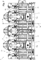
- the harvesting head for corn cobs according to the invention is indicated overall with the number 1.
- a combine harvester complete with wheels, motor and control station, to provide an agricultural machine for harvesting corn.
- Said machines are suitable to collect the corn cobs, separating them from the plants, preferably grown in rows which are preferably spaced between 4 dm and 8 dm and more preferably close to 5 dm apart.
- said machines preferably cut, and also preferably chop up the stalks of said corn plants.
- the harvesting head for corn cobs 1 is suitable to harvest corn along a direction of advancement 1a , and in a sense of advancement 1b, i.e. the direction in which the agricultural machine normally advances when it is in a straight line.
- the head 1 further comprises a groove 3 connected to the row separator tip 2 and establishing, with the adjoining groove 3, collection channels 4.
- the grooves 3 are known. They have a preferably convex upwards shape, so as to convey the corn cobs into the appropriate collection channels 4.
- the harvesting head 1 comprises a plurality, usually between 4 and 20, harvesting groups 10 mutually similar, parallel and mainly extending in said direction of advancement.
- Adjacent collection channels 4 are preferably spaced apart by between 4 dm and 8 dm, more preferably by between 4 dm and 6 dm, and still more preferably close to 5 dm.
- Each harvesting group 10 comprises, in addition, harvesting conveyors 5 suitable to transport the corn plants and corn cobs along the collection channels 4 and in the direction of advancement (1a) and in an opposite sense to said sense of advancement (1b).
- the harvesting conveyors 5 are also known.
- Each harvesting group 10 also comprises known de-cobbing plates 8 suitable to separate the cob from the stem when in contact with the plates 8, as described hereinafter.
- the de-cobbing plates 8 are arranged side by side and create a gap of about 4 cm that faces the collection channels 4, so as to trap the cobs dragged therein and not the stem or stalk.
- Each harvesting group 10 also comprises two squeezing rollers 6 side by side and at a much reduced distance. These are suitable to drag the corn plants positioned in the collection channels 4 downwards, so that the cobs are torn upon contact with the de-cobbing plates 8 and transported by the harvesting conveyor 5.
- the squeezing rollers 6 consist of cylindrical elements extending predominantly in the direction of advancement 1a and rotatable along axes parallel to said direction of advancement 1a. They are preferably equipped with radial fins 60 and other characteristics described below.
- the adjacent harvesting groups 10 are in addition surmounted by grooves 3 and connected to the row separator tips 2.
- the head 1 further comprises stubble cutter units 7 suitable to cut the corn plants when placed in the collection channels 4.
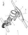
- Each stubble cutter unit 7 comprises a hub 70 rotatable along an axis of rotation 70a not parallel to the horizontal plane, and preferably close to vertical, in particular inclined by an angle of between 3° and 20° with respect to the vertical direction.
- Said hub 70 is arranged in a harvesting group 10, preferably under one of the grooves 3.
- Each stubble cutter unit 7 also comprises a number of rotating blades 71, at least one, and preferably between 2 and 4, and more preferably two.
- the rotating blades 71 are perpendicular to the axis of rotation 70a.
- the rotating blades 71 are suitable to cut, and in cutting use, the corn plants are arranged in both collection channels 4 mutually adjacent and contiguous to the harvesting group 10, on which the hub 70 of the same blade is placed.
- a stubble cutter unit 7 is suitably arranged for every two harvesting groups 10.
- the rotating blades 70 are each between 3 dm and 6 dm and more preferably 4 dm in length from the axis of rotation 70a.
- the squeezing rollers 6 preferably comprise retention means 61, suitable to hold the corn plants so as to facilitate and to allow said cutting.
- the retaining means 61 preferably consist of non-parallel grooves, preferably perpendicular to the direction of advancement 1a, or consist of fins suitable to trap the corn plants.
- Each stubble cutter unit 7 also comprises a known disconnectable coupling joint 72, preferably connected to a handling system 73, common to all the stubble cutter units 7.
- a feed auger is preferably present, suitable to transport the produce to the combine harvester intake.
- the harvesting head for corn cobs 1, and the machine that includes it, are positioned on the field preferably aligning the collection channels 4 with rows of corn plants.
- the advancing machine correctly channels said plants through the row separating tips 2, dragging down plants arranged therein through the squeezing rollers 6.
- each stubble cutter unit 7 cuts the plants of two adjacent collection channels 4.
- the cobs thus arrive in contact with the plates and are separated here from the rest of the plant as a result of the impact or the contact itself.
- corn cobs are conveyed by the harvesting conveyors 5 to the feed auger, suitable for transporting the produce to the combine harvester intake.
- the harvesting head for corn cobs 1 according to the invention achieves significant advantages.
- said head 1 comprises a smaller number of stubble cutter units 7 it is consequently simpler, inexpensive and quickly maintainable.
- the stubble cutter units 7 are actually the most complex part of the head 1, since they also comprise the coupling joint 72 and complex handling gear.
- the large diameter of the rotating blades 71 allows a better cutting of the plants themselves, in particular when combined with the retaining means 61 on the squeezing rollers 6.
Landscapes
- Life Sciences & Earth Sciences (AREA)
- Environmental Sciences (AREA)
- Harvesting Machines For Specific Crops (AREA)
Claims (10)
- Erntevorsatz (1) für Maiskolben, geeignet zum Ernten von Maispflanzen entlang einer Fahrtrichtung (1a) und entlang einer Fahrtrichtung (1b) und umfassend:- Reihentrenner-Spitzen (2), die geeignet sind, die genannten Maispflanzen entlang von Erntekanälen (4) zu sammeln und im Wesentlichen in zu der genannten Fahrtrichtung (1a) parallel verlaufen,- Hauben (3), die mit den genannten Reihentrenner-Spitzen (2) verbunden sind und die genannten Erntekanäle (4) definieren, die geeignet sind, einen Aufnahmebereich der genannten Maispflanzen zu bilden, wenn diese noch nicht geschnitten sind,- eine Vielzahl von Erntegruppen (10), die nebeneinanderliegend gefluchtet sind und vorrangig in der genannten Fahrtrichtung (1a) verlaufen, wobei jede der genannten Erntegruppen (10) Folgendes umfasst:- Ernteketten (5), die geeignet sind, die genannten Maispflanzen und die genannten Kolben in der genannten Fahrtrichtung (1a) und in einer der genannten Fahrtrichtung entgegengesetzten Richtung (1b) in den genannten Erntekanälen (4) zu befördern,- Pflückplatten (8), die geeignet sind, die genannten Maiskolben vom Stiel zu trennen und die einen Spalt entlang einer der genannten Erntekanäle (4) definieren,- zwei Reißwalzen (6), die vor dem genannten Erntekanal (4) liegen und geeignet sind, die genannten in den genannten Erntekanälen (4) angeordnete Maispflanzen nach unten zu ziehen, so dass die genannten Kolben im Kontakt mit den genannten Pflückplatten (8) abgerissen und von den genannten Erntekanälen (4) befördert werden,- wobei die nebeneinanderliegenden Erntegruppen (10) von den genannten Hauben (3) abgedeckt werden und mit den genannten Reihentrenner-Spitzen (2) verbunden sind,- wobei der genannte Erntevorsatz (1) außerdem Häckslergruppen (7) umfasst, die geeignet sind, die genannten Maispflanzen zu schneiden, wenn sie in den genannten Erntekanälen (4) angeordnet sind,- wobei jede der genannten Häckslergruppen (7) Folgendes umfasst:- eine Nabe (70), die entlang einer nicht zur Horizontalebene parallelen Drehachse (70a) gedreht werden kann und unter einer der genannten Hauben (3) angeordnet ist,- mindestens ein Drehmesser (71), das mit der genannten Nabe (70) verbunden und geeignet ist, die aufgrund seiner Länge aneinander angrenzend in zwei der genannten Erntekanäle (4) angeordneten genannten Maispflanzen zu scheiden,- und wobei der genannte Erntevorsatz dadurch gekennzeichnet ist, dass:- zwei der angrenzenden genannten Häckslergruppen (7) unter zwei nicht aneinander angrenzenden jeweiligen Hauben (3) angeordnet sind, so dass alle genannten Drehmesser (71) in derselben Ebene liegen können.
- Erntevorsatz (1) nach dem vorangegangenen Anspruch, bei dem eine genannte Häckslergruppe (7) alle zwei Erntegruppen (10) vorhanden ist.
- Erntevorsatz (1) nach Anspruch 1 oder 2, bei dem die genannten Drehmesser (61) in der Anzahl von jeweils zwei pro Nabe (70) vorhanden sind.
- Erntevorsatz (1) nach einem oder mehreren der vorangegangenen Ansprüche, bei dem die genannten Drehmesser (71) eine Länge ausgehend von der Drehachse (70a) zwischen 3 dm und 6 dm aufweisen.
- Erntevorsatz (1) nach dem vorangegangenen Anspruch, bei dem die genannten Drehmesser (71) jeweils eine Länge ausgehend von der Drehachse (70a) von 4 dm aufweisen.
- Erntevorsatz (1) nach einem oder mehreren der vorangegangenen Ansprüche, bei dem die genannten Reißwalzen (6) Rückhaltemittel (61) umfassen, die geeignet sind, die Maispflanzen zurückzuhalten, um ihr Schneiden auch dann zu gestatten, wenn die genannten Drehmesser (71) eine mit der genannten Fahrtrichtung übereinstimmende Bewegungsrichtung aufweisen.
- Erntevorsatz (1) nach dem vorangegangenen Anspruch, bei dem die genannten Rückhaltemittel (61) aus nicht zu der genannten Fahrtrichtung (1a) parallelen Nuten bestehen.
- Erntevorsatz (1) nach dem vorangegangenen Anspruch, bei dem die genannten Rückhaltemittel (61) aus in radialer Richtung verlaufenden Lamellen bestehen, die geeignet sind, die Maispflanzen zurückzuhalten und dabei nicht zu schneiden.
- Erntevorsatz (1) nach dem vorangegangenen Anspruch, bei dem jede der genannten Häckslergruppen (7) ein Kupplungsgelenk (72) umfasst.
- Mähdrescher, umfassend einen Dreschflegel und einen Erntevorsatz (1) nach einem oder mehreren der vorangegangenen Ansprüche.
Applications Claiming Priority (1)
| Application Number | Priority Date | Filing Date | Title |
|---|---|---|---|
| ITUB20151667 | 2015-06-25 |
Publications (2)
| Publication Number | Publication Date |
|---|---|
| EP3108739A1 EP3108739A1 (de) | 2016-12-28 |
| EP3108739B1 true EP3108739B1 (de) | 2021-08-04 |
Family
ID=54542305
Family Applications (1)
| Application Number | Title | Priority Date | Filing Date |
|---|---|---|---|
| EP16174249.9A Active EP3108739B1 (de) | 2015-06-25 | 2016-06-13 | Erntevorsatz für maiskolben |
Country Status (1)
| Country | Link |
|---|---|
| EP (1) | EP3108739B1 (de) |
Families Citing this family (2)
| Publication number | Priority date | Publication date | Assignee | Title |
|---|---|---|---|---|
| CN108012662A (zh) * | 2018-01-22 | 2018-05-11 | 成都数智凌云科技有限公司 | 一种玉米收割装置 |
| CN113068512B (zh) * | 2021-04-07 | 2022-03-11 | 中国农业大学 | 一种青贮玉米收获机的仿形破茬装置及方法 |
Family Cites Families (5)
| Publication number | Priority date | Publication date | Assignee | Title |
|---|---|---|---|---|
| US5330114A (en) | 1993-05-28 | 1994-07-19 | Trenkamp Michael J | Shredder attachment for combine corn head |
| IT1266440B1 (it) | 1993-11-16 | 1996-12-30 | Capello R & F Flli | Elemento di testata per la raccolta del mais con trinciastocchi, applicabile su mietitrebbia. |
| PL2335472T3 (pl) | 2009-12-18 | 2012-12-31 | Olimac Srl | Sieczkarnia i maszyna do zbierania kukurydzy wyposażona w taką sieczkarnię |
| EP2335470A1 (de) | 2009-12-18 | 2011-06-22 | Olimac S.r.l. | Maschine zum Ernten von Mais |
| IT1401567B1 (it) | 2010-08-03 | 2013-07-26 | Cressoni S P A Flli | Macchina spannocchiatrice munita di mezzi di soffiaggio e relativo metodo di spannocchiatura. |
-
2016
- 2016-06-13 EP EP16174249.9A patent/EP3108739B1/de active Active
Non-Patent Citations (1)
| Title |
|---|
| None * |
Also Published As
| Publication number | Publication date |
|---|---|
| EP3108739A1 (de) | 2016-12-28 |
Similar Documents
| Publication | Publication Date | Title |
|---|---|---|
| EP3153006B1 (de) | Nicht-reihenempfindlicher dreschmaisplfücker | |
| US9386747B2 (en) | Stalk roll integrated crop scraper | |
| US6119443A (en) | Corn harvesting attachment | |
| US6430907B2 (en) | Intake and plucking arrangement as well as a harvesting machine | |
| US7905079B2 (en) | Row-insensitive feeding and picking device for an agricultural header | |
| US10194589B2 (en) | Multi-row sugarcane harvester feed section | |
| US20120204528A1 (en) | High speed corn row unit deck plates | |
| US9386745B2 (en) | Corn header for a forage harvester including a side separating mechanism | |
| US20160007530A1 (en) | Stalk shredder for a corn harvesting device | |
| US20140260164A1 (en) | Multi-knife straight helical stalk roll knife | |
| AU2013273642B2 (en) | Row insensitive biomass harvesting and billeting system and method | |
| CN106258194A (zh) | 收割机 | |
| US9775292B2 (en) | Non-row sensitive forage harvester header | |
| US9326448B2 (en) | Roller shell for a conditioning roller | |
| US3930354A (en) | Harvesting device in particular for an ensilaging machine | |
| EP2301324B1 (de) | Mähhäcksler mit Überlastschutz | |
| KR102366446B1 (ko) | 풋옥수수 수확기 | |
| US8117811B1 (en) | Cutter system for a header of a forage harvester | |
| EP3108739A1 (de) | Erntevorsatz für maiskolben | |
| US9635807B2 (en) | Agricultural header row unit for harvesting stalk residue | |
| CN106888678A (zh) | 玉米收割机 | |
| US7905078B2 (en) | Machine for the harvest of stalk-like plants | |
| CN106888680A (zh) | 茎穗兼收式鲜食玉米收割机 | |
| US20060185340A1 (en) | Cutting and threshing header for harvesting machine | |
| CN116267200B (zh) | 一种籽瓜收获机用瓜蔓分离装置 |
Legal Events
| Date | Code | Title | Description |
|---|---|---|---|
| PUAI | Public reference made under article 153(3) epc to a published international application that has entered the european phase |
Free format text: ORIGINAL CODE: 0009012 |
|
| STAA | Information on the status of an ep patent application or granted ep patent |
Free format text: STATUS: THE APPLICATION HAS BEEN PUBLISHED |
|
| AK | Designated contracting states |
Kind code of ref document: A1 Designated state(s): AL AT BE BG CH CY CZ DE DK EE ES FI FR GB GR HR HU IE IS IT LI LT LU LV MC MK MT NL NO PL PT RO RS SE SI SK SM TR |
|
| AX | Request for extension of the european patent |
Extension state: BA ME |
|
| STAA | Information on the status of an ep patent application or granted ep patent |
Free format text: STATUS: REQUEST FOR EXAMINATION WAS MADE |
|
| 17P | Request for examination filed |
Effective date: 20170216 |
|
| RBV | Designated contracting states (corrected) |
Designated state(s): AL AT BE BG CH CY CZ DE DK EE ES FI FR GB GR HR HU IE IS IT LI LT LU LV MC MK MT NL NO PL PT RO RS SE SI SK SM TR |
|
| STAA | Information on the status of an ep patent application or granted ep patent |
Free format text: STATUS: EXAMINATION IS IN PROGRESS |
|
| 17Q | First examination report despatched |
Effective date: 20190726 |
|
| GRAP | Despatch of communication of intention to grant a patent |
Free format text: ORIGINAL CODE: EPIDOSNIGR1 |
|
| STAA | Information on the status of an ep patent application or granted ep patent |
Free format text: STATUS: GRANT OF PATENT IS INTENDED |
|
| INTG | Intention to grant announced |
Effective date: 20210407 |
|
| GRAS | Grant fee paid |
Free format text: ORIGINAL CODE: EPIDOSNIGR3 |
|
| GRAA | (expected) grant |
Free format text: ORIGINAL CODE: 0009210 |
|
| STAA | Information on the status of an ep patent application or granted ep patent |
Free format text: STATUS: THE PATENT HAS BEEN GRANTED |
|
| AK | Designated contracting states |
Kind code of ref document: B1 Designated state(s): AL AT BE BG CH CY CZ DE DK EE ES FI FR GB GR HR HU IE IS IT LI LT LU LV MC MK MT NL NO PL PT RO RS SE SI SK SM TR |
|
| REG | Reference to a national code |
Ref country code: GB Ref legal event code: FG4D |
|
| REG | Reference to a national code |
Ref country code: AT Ref legal event code: REF Ref document number: 1416005 Country of ref document: AT Kind code of ref document: T Effective date: 20210815 |
|
| REG | Reference to a national code |
Ref country code: CH Ref legal event code: EP |
|
| REG | Reference to a national code |
Ref country code: DE Ref legal event code: R096 Ref document number: 602016061483 Country of ref document: DE |
|
| REG | Reference to a national code |
Ref country code: IE Ref legal event code: FG4D |
|
| REG | Reference to a national code |
Ref country code: LT Ref legal event code: MG9D |
|
| REG | Reference to a national code |
Ref country code: NL Ref legal event code: MP Effective date: 20210804 |
|
| REG | Reference to a national code |
Ref country code: AT Ref legal event code: MK05 Ref document number: 1416005 Country of ref document: AT Kind code of ref document: T Effective date: 20210804 |
|
| PG25 | Lapsed in a contracting state [announced via postgrant information from national office to epo] |
Ref country code: HR Free format text: LAPSE BECAUSE OF FAILURE TO SUBMIT A TRANSLATION OF THE DESCRIPTION OR TO PAY THE FEE WITHIN THE PRESCRIBED TIME-LIMIT Effective date: 20210804 Ref country code: RS Free format text: LAPSE BECAUSE OF FAILURE TO SUBMIT A TRANSLATION OF THE DESCRIPTION OR TO PAY THE FEE WITHIN THE PRESCRIBED TIME-LIMIT Effective date: 20210804 Ref country code: SE Free format text: LAPSE BECAUSE OF FAILURE TO SUBMIT A TRANSLATION OF THE DESCRIPTION OR TO PAY THE FEE WITHIN THE PRESCRIBED TIME-LIMIT Effective date: 20210804 Ref country code: FI Free format text: LAPSE BECAUSE OF FAILURE TO SUBMIT A TRANSLATION OF THE DESCRIPTION OR TO PAY THE FEE WITHIN THE PRESCRIBED TIME-LIMIT Effective date: 20210804 Ref country code: ES Free format text: LAPSE BECAUSE OF FAILURE TO SUBMIT A TRANSLATION OF THE DESCRIPTION OR TO PAY THE FEE WITHIN THE PRESCRIBED TIME-LIMIT Effective date: 20210804 Ref country code: PT Free format text: LAPSE BECAUSE OF FAILURE TO SUBMIT A TRANSLATION OF THE DESCRIPTION OR TO PAY THE FEE WITHIN THE PRESCRIBED TIME-LIMIT Effective date: 20211206 Ref country code: NO Free format text: LAPSE BECAUSE OF FAILURE TO SUBMIT A TRANSLATION OF THE DESCRIPTION OR TO PAY THE FEE WITHIN THE PRESCRIBED TIME-LIMIT Effective date: 20211104 Ref country code: AT Free format text: LAPSE BECAUSE OF FAILURE TO SUBMIT A TRANSLATION OF THE DESCRIPTION OR TO PAY THE FEE WITHIN THE PRESCRIBED TIME-LIMIT Effective date: 20210804 Ref country code: BG Free format text: LAPSE BECAUSE OF FAILURE TO SUBMIT A TRANSLATION OF THE DESCRIPTION OR TO PAY THE FEE WITHIN THE PRESCRIBED TIME-LIMIT Effective date: 20211104 Ref country code: LT Free format text: LAPSE BECAUSE OF FAILURE TO SUBMIT A TRANSLATION OF THE DESCRIPTION OR TO PAY THE FEE WITHIN THE PRESCRIBED TIME-LIMIT Effective date: 20210804 |
|
| PG25 | Lapsed in a contracting state [announced via postgrant information from national office to epo] |
Ref country code: PL Free format text: LAPSE BECAUSE OF FAILURE TO SUBMIT A TRANSLATION OF THE DESCRIPTION OR TO PAY THE FEE WITHIN THE PRESCRIBED TIME-LIMIT Effective date: 20210804 Ref country code: LV Free format text: LAPSE BECAUSE OF FAILURE TO SUBMIT A TRANSLATION OF THE DESCRIPTION OR TO PAY THE FEE WITHIN THE PRESCRIBED TIME-LIMIT Effective date: 20210804 Ref country code: GR Free format text: LAPSE BECAUSE OF FAILURE TO SUBMIT A TRANSLATION OF THE DESCRIPTION OR TO PAY THE FEE WITHIN THE PRESCRIBED TIME-LIMIT Effective date: 20211105 |
|
| PG25 | Lapsed in a contracting state [announced via postgrant information from national office to epo] |
Ref country code: NL Free format text: LAPSE BECAUSE OF FAILURE TO SUBMIT A TRANSLATION OF THE DESCRIPTION OR TO PAY THE FEE WITHIN THE PRESCRIBED TIME-LIMIT Effective date: 20210804 |
|
| PG25 | Lapsed in a contracting state [announced via postgrant information from national office to epo] |
Ref country code: DK Free format text: LAPSE BECAUSE OF FAILURE TO SUBMIT A TRANSLATION OF THE DESCRIPTION OR TO PAY THE FEE WITHIN THE PRESCRIBED TIME-LIMIT Effective date: 20210804 |
|
| REG | Reference to a national code |
Ref country code: DE Ref legal event code: R097 Ref document number: 602016061483 Country of ref document: DE |
|
| PG25 | Lapsed in a contracting state [announced via postgrant information from national office to epo] |
Ref country code: SM Free format text: LAPSE BECAUSE OF FAILURE TO SUBMIT A TRANSLATION OF THE DESCRIPTION OR TO PAY THE FEE WITHIN THE PRESCRIBED TIME-LIMIT Effective date: 20210804 Ref country code: SK Free format text: LAPSE BECAUSE OF FAILURE TO SUBMIT A TRANSLATION OF THE DESCRIPTION OR TO PAY THE FEE WITHIN THE PRESCRIBED TIME-LIMIT Effective date: 20210804 Ref country code: RO Free format text: LAPSE BECAUSE OF FAILURE TO SUBMIT A TRANSLATION OF THE DESCRIPTION OR TO PAY THE FEE WITHIN THE PRESCRIBED TIME-LIMIT Effective date: 20210804 Ref country code: EE Free format text: LAPSE BECAUSE OF FAILURE TO SUBMIT A TRANSLATION OF THE DESCRIPTION OR TO PAY THE FEE WITHIN THE PRESCRIBED TIME-LIMIT Effective date: 20210804 Ref country code: CZ Free format text: LAPSE BECAUSE OF FAILURE TO SUBMIT A TRANSLATION OF THE DESCRIPTION OR TO PAY THE FEE WITHIN THE PRESCRIBED TIME-LIMIT Effective date: 20210804 Ref country code: AL Free format text: LAPSE BECAUSE OF FAILURE TO SUBMIT A TRANSLATION OF THE DESCRIPTION OR TO PAY THE FEE WITHIN THE PRESCRIBED TIME-LIMIT Effective date: 20210804 |
|
| PLBE | No opposition filed within time limit |
Free format text: ORIGINAL CODE: 0009261 |
|
| STAA | Information on the status of an ep patent application or granted ep patent |
Free format text: STATUS: NO OPPOSITION FILED WITHIN TIME LIMIT |
|
| 26N | No opposition filed |
Effective date: 20220506 |
|
| PG25 | Lapsed in a contracting state [announced via postgrant information from national office to epo] |
Ref country code: SI Free format text: LAPSE BECAUSE OF FAILURE TO SUBMIT A TRANSLATION OF THE DESCRIPTION OR TO PAY THE FEE WITHIN THE PRESCRIBED TIME-LIMIT Effective date: 20210804 |
|
| PG25 | Lapsed in a contracting state [announced via postgrant information from national office to epo] |
Ref country code: MC Free format text: LAPSE BECAUSE OF FAILURE TO SUBMIT A TRANSLATION OF THE DESCRIPTION OR TO PAY THE FEE WITHIN THE PRESCRIBED TIME-LIMIT Effective date: 20210804 |
|
| REG | Reference to a national code |
Ref country code: CH Ref legal event code: PL |
|
| REG | Reference to a national code |
Ref country code: BE Ref legal event code: MM Effective date: 20220630 |
|
| GBPC | Gb: european patent ceased through non-payment of renewal fee |
Effective date: 20220613 |
|
| PG25 | Lapsed in a contracting state [announced via postgrant information from national office to epo] |
Ref country code: LU Free format text: LAPSE BECAUSE OF NON-PAYMENT OF DUE FEES Effective date: 20220613 Ref country code: LI Free format text: LAPSE BECAUSE OF NON-PAYMENT OF DUE FEES Effective date: 20220630 Ref country code: IE Free format text: LAPSE BECAUSE OF NON-PAYMENT OF DUE FEES Effective date: 20220613 Ref country code: CH Free format text: LAPSE BECAUSE OF NON-PAYMENT OF DUE FEES Effective date: 20220630 |
|
| PG25 | Lapsed in a contracting state [announced via postgrant information from national office to epo] |
Ref country code: GB Free format text: LAPSE BECAUSE OF NON-PAYMENT OF DUE FEES Effective date: 20220613 Ref country code: BE Free format text: LAPSE BECAUSE OF NON-PAYMENT OF DUE FEES Effective date: 20220630 |
|
| P01 | Opt-out of the competence of the unified patent court (upc) registered |
Effective date: 20230601 |
|
| PG25 | Lapsed in a contracting state [announced via postgrant information from national office to epo] |
Ref country code: HU Free format text: LAPSE BECAUSE OF FAILURE TO SUBMIT A TRANSLATION OF THE DESCRIPTION OR TO PAY THE FEE WITHIN THE PRESCRIBED TIME-LIMIT; INVALID AB INITIO Effective date: 20160613 |
|
| PG25 | Lapsed in a contracting state [announced via postgrant information from national office to epo] |
Ref country code: MK Free format text: LAPSE BECAUSE OF FAILURE TO SUBMIT A TRANSLATION OF THE DESCRIPTION OR TO PAY THE FEE WITHIN THE PRESCRIBED TIME-LIMIT Effective date: 20210804 Ref country code: CY Free format text: LAPSE BECAUSE OF FAILURE TO SUBMIT A TRANSLATION OF THE DESCRIPTION OR TO PAY THE FEE WITHIN THE PRESCRIBED TIME-LIMIT Effective date: 20210804 |
|
| PG25 | Lapsed in a contracting state [announced via postgrant information from national office to epo] |
Ref country code: TR Free format text: LAPSE BECAUSE OF FAILURE TO SUBMIT A TRANSLATION OF THE DESCRIPTION OR TO PAY THE FEE WITHIN THE PRESCRIBED TIME-LIMIT Effective date: 20210804 |
|
| PG25 | Lapsed in a contracting state [announced via postgrant information from national office to epo] |
Ref country code: MT Free format text: LAPSE BECAUSE OF FAILURE TO SUBMIT A TRANSLATION OF THE DESCRIPTION OR TO PAY THE FEE WITHIN THE PRESCRIBED TIME-LIMIT Effective date: 20210804 |
|
| PGFP | Annual fee paid to national office [announced via postgrant information from national office to epo] |
Ref country code: DE Payment date: 20250618 Year of fee payment: 10 |
|
| PGFP | Annual fee paid to national office [announced via postgrant information from national office to epo] |
Ref country code: FR Payment date: 20250626 Year of fee payment: 10 |
|
| PGFP | Annual fee paid to national office [announced via postgrant information from national office to epo] |
Ref country code: IT Payment date: 20260320 Year of fee payment: 11 |