EP3108783A1 - Spatel, insbesondere für küchengeräte - Google Patents
Spatel, insbesondere für küchengeräte Download PDFInfo
- Publication number
- EP3108783A1 EP3108783A1 EP16174171.5A EP16174171A EP3108783A1 EP 3108783 A1 EP3108783 A1 EP 3108783A1 EP 16174171 A EP16174171 A EP 16174171A EP 3108783 A1 EP3108783 A1 EP 3108783A1
- Authority
- EP
- European Patent Office
- Prior art keywords
- spatula
- working
- longitudinal axis
- recess
- indentation
- Prior art date
- Legal status (The legal status is an assumption and is not a legal conclusion. Google has not performed a legal analysis and makes no representation as to the accuracy of the status listed.)
- Granted
Links
Images

Classifications
-
- A—HUMAN NECESSITIES
- A47—FURNITURE; DOMESTIC ARTICLES OR APPLIANCES; COFFEE MILLS; SPICE MILLS; SUCTION CLEANERS IN GENERAL
- A47J—KITCHEN EQUIPMENT; COFFEE MILLS; SPICE MILLS; APPARATUS FOR MAKING BEVERAGES
- A47J43/00—Implements for preparing or holding food, not provided for in other groups of this subclass
- A47J43/28—Other culinary hand implements, e.g. spatulas, pincers, forks or like food holders, ladles, skimming ladles, cooking spoons; Spoon-holders attached to cooking pots
- A47J43/281—Cooking spoons; Ladles
-
- A—HUMAN NECESSITIES
- A47—FURNITURE; DOMESTIC ARTICLES OR APPLIANCES; COFFEE MILLS; SPICE MILLS; SUCTION CLEANERS IN GENERAL
- A47J—KITCHEN EQUIPMENT; COFFEE MILLS; SPICE MILLS; APPARATUS FOR MAKING BEVERAGES
- A47J43/00—Implements for preparing or holding food, not provided for in other groups of this subclass
- A47J43/28—Other culinary hand implements, e.g. spatulas, pincers, forks or like food holders, ladles, skimming ladles, cooking spoons; Spoon-holders attached to cooking pots
- A47J43/288—Spatulas; Scrapers; Multi-purpose hand implements
Definitions
- the invention relates to a spatula according to the features of the preamble of claim 1.
- Spatulas of the aforementioned type are well known in the art. These spatulas essentially have a gripping part for gripping and a working part arranged thereon, which working part may have the form of a scraper with integrated working indentation, in particular spoon dish. Such spatulas are used, for example, for cleaning a mixing vessel of a kitchen appliance and / or for removing or adding food and / or for stirring. In this case, the user can reach through the opening of the mixing vessel through the spatula in order to remove or feed the food to the mixing process. It is possible to get into the blender jar, as the opening of the blender jar is big enough.
- the invention has the object to provide a spatula, which provides a high utility value in a kitchen application.
- a working recess is formed on both working part sides and the grip part has at least one handle dent, whose opening edges span a plane, wherein a surface normal of this plane with respect to the longitudinal extent of the spatula points in substantially the same radial direction as a surface normal of a plane which is spanned by opening edges of a working recess.
- radial direction designates a direction starting from a geometric center longitudinal axis of the spatula, based on a cross section in which the central longitudinal axis is formed as a point.
- the aforementioned surface normal of the Griffeinbuchtung and the aforementioned surface normal of the work dent substantially in the same radial direction, which is understood not only those embodiments in which the surface normal fall exactly in the same radial direction, but also those in which the two Surface normal have an angle not equal to zero to each other, in particular an angle of up to 45 °.
- the handle part has only one handle dent or has more Griffeinbuchtitch.
- multiple Griffeinbuchtitch they can be arranged in the circumferential direction and / or in the direction of the longitudinal axis of the spatula.
- a handle dent or a work dent can be formed such that the opening edges span a plurality of planes whose surface normals rotate along a helical path about the longitudinal axis.
- a surface normal to a level of Griffeinbuchtung has an angle> 0 and ⁇ 45 ° to a surface normal of a plane of the working indentation, so that the user can still assign a certain orientation of the working indentation to the sensed orientation of the grip indentation.
- the user By palpation and / or consideration of this spatial orientation of the handle dent in the radial direction of the spatula, the user simultaneously obtains information about the spatial orientation of the working part or the working dent of the working part. Since the Griffeinbuchtung the handle part is palpable, the user can perceive this information haptic. It is not necessary for the user to additionally see the orientation of the handle dent of the working part and / or the working dent. Since the spatial orientation of the handle dent or Griffeinbuchtitch corresponds to the spatial orientation of the working part, the user acquires immediate knowledge of which direction the working sub-pages are currently addressed.
- the Griffeinbuchtung invention can also be used to measure small or smallest amounts added, for example, spices, and bring in the mixing vessel of the household mixer.
- the grip part of the spatula also fulfills the function of a tool for measuring and adding additives, such as spices, into the mixing vessel.
- the user can carry out the desired activities equally with both working part pages.
- a plurality of sides of the grip part or only one side have one or more handle indentations.
- the handle indentation and the working indentation are aligned on a straight line, which straight line extends in particular parallel to the longitudinal extension of the spatula.
- This spatial relationship of Griffeinbuchtung and Häeinbuchtung is understood by the user mentally particularly simple and intuitive.
- aligned on a straight line are also to be understood those embodiments in which the work dent and the handle dent are aligned parallel to the straight line, but are offset transversely to this line.
- This also includes in particular those embodiments in which the working part is shaped so that the geometric center of gravity of the working recess is adjacent to the linear extension of the handle part.
- Such shaped spatula can be used advantageously for cleaning the inner wall of a Mixgefäßes, since the work dent with a lower than conventional spatula tilting can come into contact with the inner wall.
- the shape or dimension of the handle dent in the direction of the longitudinal extension of the spatula varies.
- the user can not only feel the spatial orientation of the spatula, but also the position of his hand on the spatula in the direction of the longitudinal axis of the spatula, that is the distance between his hand and, for example, the working part.
- the handle dent can taper in the direction of the working part and / or have other haptic position markings. Based on the position-dependent width of wedge-shaped Griffeinbuchtung on the handle - for example, in relation to the size of the finger of the user - the user can feel and derive his current finger position.
- other haptic position markings are conceivable, for example, markings similar to a braille script.
- the user of the spatula by the invention also receives information about the orientation of the working sub-pages, if the orientation of the spatula is optically not visible within the mixing vessel.
- the Griffeinbuchtung may also be a continuation of the arranged on the working part termeseinbuchtung.
- a grip dent is understood, which is either formed integrally with the work dent, or at least has the same orientation in the direction of the longitudinal extension of the spatula.
- the recesses of the working part and the handle part can be aligned along a common straight line.
- the invention results in a haptic information for the user when touching the spatula.
- the user can feel the spatial orientation of the working part sides by means of the handle indentation without having to see them. Especially when working in the interior of a mixing vessel, this is a great advantage.
- several Griffeinbuchtungen can be distributed along the circumference of the handle portion or along the longitudinal extent.
- a change in handle dent in the direction of the longitudinal axis of the spatula such as a change in width or depth, may facilitate recognition of the user's current hand position on the spatula.
- a working indentation may have on the side facing the gripping part a channel-like narrowing section whose width transversely to the Longitudinal axis of the spatula in an inlet region in the remaining region of the working indentation of half or less corresponds to a maximum width of the working indentation.
- the spatula thus not only has a circular or oval working indentation, but rather a groove-like narrowing portion, which forms the region of the working indentation facing the gripping part.
- the trough-like rejuvenation section can be used to measure food in smaller quantities and bring in the mixing vessel. For example, it is possible to meter off oil by means of the groove-like narrowing section and to let it run in via the inlet area into the remaining area of the working recess, where it mixes with other ingredients present in the working recess.
- a maximum length of the working dent including the taper portion parallel to the longitudinal axis of the spatula will be at least twice as large as the greatest width of the working dent transverse to the longitudinal axis of the spatula.
- size length and “largest width” of the working recess in each case denote the maximum length or width between two points of the opening edges of the working dent, which lie on a common straight line parallel to the longitudinal axis of the spatula or transverse to the longitudinal axis of the spatula extends.
- This configuration results in an elongated shape of the working dent, which extends in the direction of the handle part.
- the geometric center of gravity (center point) of the working indentation may, for example, coincide with the geometric center of gravity of the working part, wherein the tapered portion of the work well extending from this focus in the direction of the handle part.
- a maximum length of the working dent including the taper portion parallel to the longitudinal axis of the spatula be at least two times to ten times at most, in particular three times to five times, a maximum width of the working dent transverse to the longitudinal axis of the spatula spatula.
- the working recess advantageously has a greater length than width, in particular a length three to five times greater than width. This results in an elongated shape of the working recess, which has an end in the form of a tapering portion in the direction of the handle part.
- the working part and the handle part are separated in an area where a shield is usually attached to the spatula to limit the possible depth of engagement of the spatula into a vessel. This is advantageous with respect to the longitudinal axis of the spatula outside the working dent and outside of a longitudinal range in which a user usually touches the spatula.
- the working indentation has a tapering section extending in the direction of the gripping part, the width of which is transverse to the longitudinal axis of the spatula greater along a longitudinal section aligned parallel to the longitudinal axis and having a length of at least one tenth of the greatest length of the working recess Zero, but at most half as large as a transverse to the longitudinal axis largest width of the working dent.
- the tapered portion has a portion of length at least one tenth of the greatest length of the working recess Width which is at most half as large as the largest width of the working dent. This results in the region of the taper section, a mechanical weakening of the working part, which can lead to increased flexibility of the spatula in this area. This makes it possible, for example, when cleaning a mixing vessel to bend the spatula so that it optimally applies to the contours of the inner wall of the mixing vessel. Depending on the nature of the material of the spatula in the region of the tapering section, in particular the elasticity of the material, depending on the applied force, a more or less pronounced deformation of the spatula may occur.
- the tapering section can be aligned parallel to the longitudinal axis of the spatula, the tapering section in particular having parallel edge boundaries.
- the tapering section it is also possible for the tapering section to be tapered in the direction of the grip part or to have a different width variation. The special design depends on the individual requirements for the flexibility of the spatula.
- a width of the tapering section formed transversely to the longitudinal axis of the spatula has an amount of at least 25 percent to at most 75 percent, in particular 50 percent, of the locally corresponding diameter of the spatula.
- the width of the tapered portion is thus dependent on the diameter of the spatula, and it has been found in practice to be advantageous to form the width of the tapering portion within the aforementioned limits.
- the material thickness of the working part is reduced overall, which can achieve greater flexibility of the spatula in this area.
- the flexibility is advantageous in particular when the spatula is moved along an inner wall of the mixing vessel.
- the work dent is becoming an essential Part of the material of the working part recessed, so that the working part receives a total of an advantageous spring elasticity.
- the working part remains rigid and dimensionally stable in a direction substantially parallel to the working part sides, so that there are no disadvantages with respect to other uses.
- the spatula may have a shield between the handle and the working part.
- the shield prevents the food from spilling out of the blender jar during the mixing process by closing or at least shielding the opening of the blender jar.
- the pointing in the direction of the working part side of the shield is convex, in particular spherical, formed.
- This allows the spatula to be inserted into the mixing vessel until the shield is placed in the area of the opening of the mixing vessel.
- the spatula can be pivoted relative to the opening of the mixing vessel, wherein in particular a round opening remains substantially closed and even during operation of the household mixer no food can escape from the mixing vessel.
- a pivoting of the working part in the direction of the inner wall of the mixing vessel is possible, wherein the opening remains closed by the convex side of the shield.
- a spherical curvature of the shield is suitable, since this can advantageously bring about constant closure properties due to the constant curvature.
- the pointing in the direction of the handle part side of the shield can advantageously be flat or concave, so that the user's hand can rest on as large a contact surface of the shield.
- the shield a viewing direction in which the longitudinal axis of the grip area is punctiform, a viewed from the outside at least partially convex peripheral edge which is interrupted at one or more peripheral portions of a peripheral edge edge portion which extends inwardly with respect to a continuous continuation of an adjacent convex circumferential edge edge portion.
- the plate thus has along its peripheral edge edge one or more, preferably two, peripheral edge edge portions which are designed such that when placing the spatula on a base, such as a worktop, a rolling of the spatula is prevented.
- the position of the peripheral edge section can influence the angle at which the working part sides come to rest relative to the base.
- the peripheral edge edge portions may, for example, be formed along a secant of a circular or oval cross section.
- peripheral edge can also be wavy, so that arise in the circumferential direction wave peaks and troughs.
- the peripheral edge edge portion may also have a crenellated profile, wherein the Zinnenend Schemee running from the inside to the outside with respect to the cross-sectional plane are oriented on a straight line.
- the peripheral edge edge is preferably convex, in particular oriented in the shape of a circle or oval.
- the peripheral edge which is at least partially convex when viewed from the outside, is interrupted in such a way that the peripheral edge edge section runs inward with respect to a continuous continuation of the adjacent peripheral edge edge sections.
- the continuous continuation is related to the respective radius of curvature of the adjacent peripheral edge edge portions. This local radius can be averaged over a circumferential angle range of 5 °, for example.
- peripheral edge edge portions also over the edge region of the shield projecting shelf lugs are conceivable.
- a peripheral edge portion of the edge portion of the shield viewed in the longitudinal extension of the spatula has an angle ⁇ 0 ° relative to a plane defined by opening edges of a working indentation, preferably an angle between 20 ° and 70 °, more preferably an angle of approximately 45 °.
- An angle of this magnitude between the working part and the peripheral edge portion ie at the same time the pad, ensures that liquid or solid food parts can drip or drain from the spatula.
- the working part does not come into contact with the pad.
- the working part has at least two material regions of different moduli of elasticity, wherein in particular a material region with a larger modulus of elasticity is surrounded by a material region having a lower modulus of elasticity.
- the modulus of elasticity is greater, the more resistance a material opposes elastic deformation. It is thus a measure of the stiffness of a body, wherein the stiffness also depends on the geometry of the body.
- the fact that the material region with a larger modulus of elasticity according to the invention is surrounded by a material region with a softer modulus of elasticity, results in a greater deformability of the surface of the working part, so that this can particularly advantageously adapt to the geometry of the mixing vessel.
- the working part is given a corresponding rigidity by the inner material with a larger modulus of elasticity, which is required in order to be able to carry out a cleaning of the mixing vessel.
- the materials may be, for example, different plastics.
- a material having a low modulus of elasticity is, for example, a soft plastic which has a modulus of elasticity below 1000 N / mm 2 .
- plastics such as PVC, PE, TPE or nitrile.
- materials having a high elastic modulus include hard plastics having a modulus of elasticity greater than 1000 N / mm 2 , for example PBT or PMMA.
- a material having a high modulus of elasticity may also be a metal, such as steel.
- a steel core may be encased in a plastic having the lower modulus of elasticity.
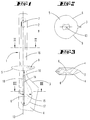
- the spatula 1 shown in the figures has a handle part 2 and a working part 3.
- the handle part 2 and the working part 3 are separated by a shield 5 in the longitudinal extension of the spatula 1.
- the spatula 1 has a longitudinal axis 13, which here corresponds to the axis of symmetry of the handle part 2.
- the working part 3 has two opposite working part sides 4, which here each have a working recess 6.
- the working recess 6 is trough-like in formed the working part 3, wherein the trough has an opening edge 17.
- a maximum length 14 is defined, which is aligned parallel to the longitudinal axis 13 of the spatula 1, and a maximum width 15, which is directed transversely to the longitudinal axis 13 of the spatula 1 is.
- the largest length 14 of the working recess 6 according to this example is approximately three times as large as the largest width 15.
- the working part 3 essentially has the outer shape of a scraper, while the working recesses 6 formed on the working part sides 4 are designed, for example, in the form of a spoon dish.
- the working recesses 6 have in the direction of the handle part 2 directed tapering portions 10 which have a relative to the maximum width of the working recess 6 reduced width.
- the depth of the taper portions 10 may differ from the remaining areas of the working recesses 6.
- the tapering portion 10 is formed like a groove and opens into an inlet region 18 in the remaining area of the working recess 6. With respect to the inlet region 18 corresponds to the width of the tapered portion 10 transverse to the longitudinal axis 13 of the spatula half or less of the largest width 15 of the working recess. 6 ,
- the handle part 2 has, for example, a handle dent 8.
- the handle recess 8 has, for example, the same spatial orientation as the working recess 6 of the working part 3, ie, that the opening edge of the handle recess 8 spans a plane whose surface normal with respect to the longitudinal extent of the spatula 1 in the same radial direction has as a surface normal a plane which is spanned by an opening edge of the working recess 6.
- the handle recess 8 may for example be a recess formed in the handle part 2 trough.
- the Griffeinbuchtung 8 gives the user In addition to a haptic information about the spatial orientation of the spatula 1 in the circumferential direction and a haptic information about the position of the hand on the handle part 2 between Griffeinbuchtung 8 and shield 5 or working part 3.
- the handle recess 8 is also visually perceptible by the user.
- the handle part 2 of the spatula 1 may also have a through opening 7, which can be used, for example, for hanging the spatula 1.
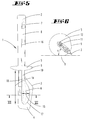
- the shield 5 has a substantially circular cross-sectional area with respect to a cross-section transverse to the longitudinal extent of the spatula 1, two circumferential edge edge portions 9 (in this case flattenings) being formed along the circumference. With respect to a radial direction of the shield 5, a portion of the working part 3 projects beyond the shield 5. From one direction along the longitudinal axis 13 of the spatula 1, the edge region of the shield 5 in the region of the peripheral edge edge portion 9 to the plane defined by the opening edges 17 of the working recess 6 at an angle ⁇ , which is about 45 ° here (see FIG. 6 ).
- the working part 3 has according to FIG. 6 a first material region 11 and a second material region 12, wherein the first material region 11 is surrounded by the second material region 12.
- the first material region 11 may comprise a material having a greater modulus of elasticity than the second material region 12.
- a soft plastic such as PVC, PE, TPE or nitrile may be used, while as a material having a larger modulus of elasticity (for example, over 1000 N / mm 2 ) PBT or PMMA is used can be.
- a first material area 11 and a second material region 12 further material regions with deviating material parameters can also be formed within the working part 3. It is recommended that the material of the second material region 12 is suitable as an outer material region for use with foods.
- the first material region 11 may comprise any material.
- plastics come, in particular for the inner, first material region 11, and metals, such as steel, in question.
- the invention works in such a way that the user grips the spatula 1 by means of the grip part 2 and, for example, leads through the opening of a mixing vessel of a household mixing appliance (not shown). Due to the convex design of pointing in the direction of the working part 3 side of the shield 5 results in a shape adaptation to the, in particular round, opening area of the mixing vessel, which ensures the operation of the household mixer that food can not be thrown out of the mixing vessel. Due to the convex shape of the shield 5, it is also possible to move the spatula 1 relative to the mixing vessel, without the shape adaptation is canceled.
- the spatula 1 Due to the design of the tapering section 10, the spatula 1 has a greater flexibility in the area of the section of the working recess 6 pointing in the direction of the grip part 2 than in the other areas of the working part. Therefore, the spatula 1 can be bent or bent there, for example during a cleaning process of the inner wall of the mixing vessel, in order to optimally follow the contour of the inner wall. By forming material regions 11, 12 with different moduli of elasticity within the working part 3, the shape adaptation can be additionally supported.
- a flexibility of other areas can also be provided of the spatula, for example in other areas of the working part, but also in the region of the handle part.
- an area can be created which provides greater flexibility in order, for example, to bend or even buckle the spatula for particular tasks or areas of application.
- the handle part 2 Griffeinbuchtitch 8 By means arranged on the handle part 2 Griffeinbuchtitch 8, it is possible for the user to recognize solely and haptic manner, which has spatial orientation of the spatula 1.
- the opening edge of the handle recess 8 biases a plane whose surface normal with respect to the longitudinal extent of the spatula 1 in the same radial direction as the surface normal of the plane, which is spanned by the opening edge of the working recess 6.
- the handle recess 8 is also visually recognizable.
- the user can use the spatula thus formed in connection with a vessel, for example a mixing vessel, whereby, based on the handle dent, he can recognize which spatial orientation of the spatula relative to the mixing vessel.
- the user wishes to remove a sample from the blender jar, for example, by means of the working part 3, he can feel haptically with which orientation he holds the spatula 1 in his hand. Thus, he can rotate the spatula 1 until one of the working part sides 4, which are advantageously symmetrical to each other, has the necessary spatial orientation. Then, the user can take a desired sample of the food contained in the mixing vessel in the spoon bowl-like work dent 6.
- the Griffeinbuchtung 8 can be used to quantitatively minor additives, such as spices, bring in the mixing vessel.
- the Griffeinbuchtung 8 for example, to measure smaller amounts of salt or the like and to introduce without loss in the mixing vessel.
- the taper portion 10 of the working recess 6 can be used to measure ingredients in small quantities and to introduce into the mixing vessel.
- the trough-like configuration of the tapering section 10 can be used to first meter out oil and then to mix it with other ingredients present in the working recess 6 before finally placing them in the mixing vessel.
- the scraper-shaped contour of the working part 3 can also be used, as usual, to scrape leftovers from the inner wall of the mixing vessel.
- the spatula 1 can be pivoted relative to the mixing vessel, wherein the opening of the mixing vessel - as previously explained - by the convex configuration of the shield 5 always conformed with the opening region of the mixing vessel remains.
- the user can use the peripheral edge portion 9 (here in the form of a flattening) of the shield 5 to place the spatula 1 in a predefined spatial orientation on a work surface.
- the peripheral edge portion 9 a rolling of the spatula 1 is prevented.
- the edge region of the shield 5 having the peripheral edge section 9 in the longitudinal extent of the spatula 1 has such a large angle ⁇ relative to the plane defined by the opening edge of the working recess 6 that liquid or food in the stowed state of the spatula 1 comes from the working part 3 can drain, but at the same time a direct contact between the working part 3 and work surface is avoided.
- the angle ⁇ between the peripheral edge edge portion is not limited to the plane defined by the opening edge of the working recess 6 that liquid or food in the stowed state of the spatula 1 comes from the working part 3 can drain, but at the same time a direct contact between the working part 3 and work surface is avoided.
- the working part 3 is determined so that the working part 3 does not touch the working surface when the spatula 1 is removed.
- the working part 3 could also be designed so that it does not project beyond the plate 5. Even then, a contact between the working part 3 and work surface would be prevented.
Landscapes
- Engineering & Computer Science (AREA)
- Mechanical Engineering (AREA)
- Food Science & Technology (AREA)
- Food-Manufacturing Devices (AREA)
Abstract
Description
- Die Erfindung betrifft einen Spatel nach den Merkmalen des Oberbegriffes des Anspruches 1.
- Spatel der vorgenannten Art sind im Stand der Technik hinreichend bekannt. Diese Spatel weisen im Wesentlichen einen Griffteil zum Anfassen sowie einen daran angeordneten Arbeitsteil auf, welcher Arbeitsteil die Form eines Schabers mit integrierter Arbeitseinbuchtung, insbesondere Löffelschale, aufweisen kann. Derartige Spatel dienen beispielsweise zur Reinigung eines Mixgefäßes eines Küchengerätes und/ oder zur Entnahme bzw. Hinzugabe von Speisen und/oder zum Rühren. Dabei kann der Nutzer mittels des Spatels durch eine Öffnung des Mixgefäßes hindurch greifen, um die Speisen zu entnehmen oder dem Mixvorgang zuzuführen. Das Hineinlangen in das Mixgefäß ist möglich, da die Öffnung des Mixgefäßes ausreichend groß ist.
- Aus der
JP 3151352 U US 2939216 A ist ein Löffelteil bekannt, dessen Arbeitsbereich insgesamt löffelartig sphärisch gekrümmt ausgebildet ist. Der Griffbereich ist mit einem erhabenen Bereich ausgebildet, der insgesamt zu einer Verdickung des Griffbereiches führt. - Ausgehend von dem dargelegten Stand der Technik beschäftigt sich die Erfindung mit der Aufgabe, einen Spatel anzugeben, der einen hohen Nutzwert bei einer Anwendung im Küchenbereich liefert.
- Diese Aufgabe ist beim Gegenstand des Anspruches 1 gelöst, wobei darauf abgestellt ist, dass auf beiden Arbeitsteilseiten jeweils eine Arbeitseinbuchtung ausgebildet ist und der Griffteil mindestens eine Griffeinbuchtung aufweist, deren Öffnungskanten eine Ebene aufspannen, wobei eine Flächennormale dieser Ebene in Bezug auf die Längserstreckung des Spatels im Wesentlichen in die gleiche radiale Richtung weist wie eine Flächennormale einer Ebene, welche durch Öffnungskanten einer Arbeitseinbuchtung aufgespannt ist.
- Der Begriff radiale Richtung bezeichnet dabei eine Richtung ausgehend von einer geometrischen Mittellängsachse des Spatels, bezogen auf einen Querschnitt, in welchem sich die Mittellängsachse als Punkt abbildet. Bevorzugt weisen die vorgenannte Flächennormale der Griffeinbuchtung und die vorgenannte Flächennormale der Arbeitseinbuchtung im Wesentlichen in die gleiche radiale Richtung, wobei darunter nicht nur solche Ausführungen verstanden werden, bei welchen die Flächennormalen exakt in die gleiche radiale Richtung fallen, sondern auch solche, bei welchen die beiden Flächennormalen einen Winkel ungleich Null zueinander aufweisen, insbesondere einen Winkel von bis zu 45°.
- Darüber hinaus ist es möglich, dass der Griffteil nur eine Griffeinbuchtung aufweist oder mehrere Griffeinbuchtungen aufweist. Im Fall mehrerer Griffeinbuchtungen können diese in Umfangsrichtung und/oder in Richtung der Längsachse des Spatels angeordnet sein.
- Darüber hinaus sind von der Erfindung auch solche Ausbildungen erfasst, bei welchen die Öffnungskanten der Griffeinbuchtung und/ oder der Arbeitseinbuchtung nicht nur eine einzige Ebene, sondern vielmehr eine Vielzahl von Ebenen aufspannen, welche einen Winkel zueinander aufweisen, das heißt deren Flächennormalen nicht parallel zueinander sind. Insbesondere kann eine Griffeinbuchtung bzw. eine Arbeitseinbuchtung so ausgebildet sein, dass die Öffnungskanten mehrere Ebenen aufspannen, deren Flächennormalen entlang einer schraubenförmigen Bahn um die Längsachse rotieren. Es empfiehlt sich auch in diesem Fall, dass eine Flächennormale einer Ebene der Griffeinbuchtung einen Winkel > 0 und < 45° zu einer Flächennormalen einer Ebene der Arbeitseinbuchtung aufweist, so dass der Nutzer der ertasteten Orientierung der Griffeinbuchtung noch eine bestimmte Orientierung der Arbeitseinbuchtung zuordnen kann.
- Durch die Ertastung und/oder Betrachtung dieser räumlichen Orientierung der Griffeinbuchtung in radialer Richtung des Spatels erlangt der Nutzer gleichzeitig eine Information über die räumliche Orientierung des Arbeitsteils bzw. der Arbeitseinbuchtung des Arbeitsteils. Da die Griffeinbuchtung des Griffteils tastbar ist, kann der Nutzer diese Information haptisch wahrnehmen. Es ist nicht erforderlich, dass der Nutzer zusätzlich die Orientierung der Griffeinbuchtung des Arbeitsteils und/ oder der Arbeitseinbuchtung sieht. Da die räumliche Orientierung der Griffeinbuchtung oder der Griffeinbuchtungen mit der räumlichen Orientierung des Arbeitsteils korrespondiert, erlangt der Nutzer unmittelbar Kenntnis davon, in welche Richtung die Arbeitsteilseiten derzeit gerichtet sind. Besonders vorteilhaft stimmen die räumlichen Orientierungen von Griffeinbuchtung und Arbeitseinbuchtung in radialer Richtung des Spatels überein, so dass die Arbeitseinbuchtung genau in die Richtung zeigt, in welche auch die von dem Nutzer ertastete Griffeinbuchtung zeigt. Dies ist insbesondere vorteilhaft, wenn der Nutzer den Spatel in einen Mixtopf eingeführt hat und den Arbeitsteil - beispielsweise aufgrund einer Abdeckung des Mixtopfes mit einem Deckel - nicht sehen kann
- Darüber hinaus kann die erfindungsgemäße Griffeinbuchtung auch dazu verwendet werden, kleine oder kleinste Zugabemengen, beispielsweise von Gewürzen, abzumessen und in das Mixgefäß des Haushaltsmixgerätes einzubringen. Somit erfüllt der Griffteil des Spatels neben der eigentlichen Grifffunktion ebenso die Funktion eines Werkzeugs zur Abmessung und Zugabe von Zusatzstoffen, wie beispielsweise Gewürzen, in das Mixgefäß.
- Der Nutzer kann mit beiden Arbeitsteilseiten gleichermaßen die gewünschten Tätigkeiten ausführen. Im Sinne der Erfindung kann vorgesehen sein, dass mehrere Seiten des Griffteils oder nur eine Seite eine oder mehrere Griffeinbuchtungen aufweisen.
- Darüber hinaus wird vorgeschlagen, dass die Griffeinbuchtung und die Arbeitseinbuchtung an einer Geraden ausgerichtet sind, welche Gerade insbesondere parallel zu der Längserstreckung des Spatels verläuft. Dieser räumliche Bezug von Griffeinbuchtung und Arbeitseinbuchtung ist von dem Nutzer gedanklich besonders einfach und intuitiv zu verstehen. Unter "an einer Geraden ausgerichtet" sind auch solche Ausführungsformen zu verstehen, bei welchen die Arbeitseinbuchtung und die Griffeinbuchtung parallel zu der Geraden ausgerichtet sind, jedoch quer zu dieser Geraden versetzt sind. Hierunter fallen insbesondere auch solche Ausbildungen, bei welchen der Arbeitsteil so geformt ist, dass der geometrische Schwerpunkt der Arbeitseinbuchtung neben der linearen Verlängerung des Griffteils liegt.
- Derart geformte Spatel können vorteilhaft zur Reinigung der Innenwandung eines Mixgefäßes eingesetzt werden, da die Arbeitseinbuchtung mit einer gegenüber herkömmlichen Spateln geringeren Verkippung in Kontakt mit der Innenwandung gelangen kann.
- Es ist darüber hinaus vorgesehen, dass die Form oder Dimension der Griffeinbuchtung in Richtung der Längserstreckung des Spatels variiert. Somit kann der Nutzer nicht nur die räumliche Orientierung des Spatels ertasten, sondern gleichzeitig auch die Position seiner Hand an dem Spatel in Richtung der Längsachse des Spatels, das heißt die Entfernung zwischen seiner Hand und beispielsweise dem Arbeitsteil. Beispielsweise kann die Griffeinbuchtung in Richtung des Arbeitsteils keilförmig zulaufen und/ oder andere haptische Positionsmarkierungen aufweisen. Anhand der positionsabhängigen Breite der keilförmigen Griffeinbuchtung an dem Griffteil - beispielsweise im Verhältnis zu der Fingergröße des Nutzers - kann der Nutzer seine aktuelle Fingerposition ertasten und ableiten. Darüber hinaus sind auch andere haptische Positionsmarkierungen denkbar, beispielsweise Markierungen ähnlich einer Brailleschrift.
- Insgesamt erhält der Nutzer des Spatels durch die Erfindung auch dann eine Information über die Orientierung der Arbeitsteilseiten, wenn die Orientierung des Spatels innerhalb des Mixgefäßes optisch nicht erkennbar ist. Insbesondere kann die Griffeinbuchtung auch eine Fortsetzung der an dem Arbeitsteil angeordneten Arbeitseinbuchtung sein. Im Sinne einer Fortsetzung wird eine Griffeinbuchtung verstanden, welche entweder einstückig mit der Arbeitseinbuchtung ausgebildet ist, oder zumindest die gleiche Orientierung in Richtung der Längserstreckung des Spatels aufweist. Beispielsweise können die Einbuchtungen des Arbeitsteils und des Griffteils entlang einer gemeinsamen Geraden ausgerichtet sein.
- Insgesamt ergibt sich durch die Erfindung eine haptische Information für den Nutzer beim Anfassen des Spatels. Der Nutzer kann die räumliche Orientierung der Arbeitsteilseiten anhand der Griffeinbuchtung ertasten, ohne diese sehen zu müssen. Gerade bei Arbeiten im Innenbereich eines Mixgefäßes ist dies von großem Vorteil. Zudem können auch mehrere Griffeinbuchtungen entlang des Umfanges des Griffteils oder entlang dessen Längserstreckung verteilt sein. Zusätzlich kann in allen Fällen eine Veränderung der Griffeinbuchtung in Richtung der Längsachse des Spatels, beispielsweise eine Änderung der Breite oder der Tiefe, die Erkennung der aktuellen Handposition des Nutzers an dem Spatel erleichtern.
- Eine Arbeitseinbuchtung kann auf der dem Griffteil zugewandten Seite einen rinnenartigen Verjüngungsabschnitt aufweisen, dessen Breite quer zu der Längsachse des Spatels in einem Einlaufbereich in den übrigen Bereich der Arbeitseinbuchtung der Hälfte oder weniger einer größten Breite der Arbeitseinbuchtung entspricht.
- Gegenüber dem vorgenannten Stand der Technik weist der Spatel somit nicht nur eine kreisförmige oder ovale Arbeitseinbuchtung auf, sondern vielmehr einen rinnenartigen Verjüngungsabschnitt, welcher den dem Griffteil zugewandten Bereich der Arbeitseinbuchtung bildet. Der rinnenartige Verjüngungsabschnitt kann dazu verwendet werden, Speisen in kleineren Mengen abzumessen und in das Mixgefäß einzubringen. Beispielsweise ist es möglich, mittels des rinnenartigen Verjüngungsabschnittes Öl abzumessen und über den Einlaufbereich in den übrigen Bereich der Arbeitseinbuchtung einlaufen zu lassen, wo sich dieses mit weiteren Zutaten vermengt, welche in der Arbeitseinbuchtung vorhanden sind.
- Es ist vorgesehen, dass eine größte Länge der Arbeitseinbuchtung einschließlich des Verjüngungsabschnitts parallel zu der Längsachse des Spatels mindestens zwei Mal so groß ist wie die größte Breite der Arbeitseinbuchtung quer zu der Längsachse des Spatels.
- Die Begriffe "größe Länge" bzw. "größte Breite" der Arbeitseinbuchtung bezeichnen dabei jeweils die betragsmäßig größte Länge bzw. Breite zwischen zwei Punkten der Öffnungskanten der Arbeitseinbuchtung, welche auf einer gemeinsamen Gerade liegen, die parallel zu der Längsachse des Spatels bzw. quer zu der Längsachse des Spatels verläuft.
- Durch diese Ausgestaltung ergibt sich eine längliche Form der Arbeitseinbuchtung, welche sich in Richtung des Griffteils erstreckt. Der geometrische Schwerpunkt (Mittelpunkt) der Arbeitseinbuchtung kann dabei beispielsweise mit dem geometrischen Schwerpunkt des Arbeitsteils übereinstimmen, wobei sich der verjüngte Teilbereich der Arbeitseinbuchtung ausgehend von diesem Schwerpunkt in Richtung des Griffteils erstreckt.
- Es empfiehlt sich, dass eine größte Länge der Arbeitseinbuchtung einschließlich des Verjüngungsabschnitts parallel zu der Längsachse des Spatels mindestens zwei Mal so groß bis höchstens zehn Mal, insbesondere drei Mal bis fünf Mal, so groß ist wie eine größte Breite der Arbeitseinbuchtung quer zu der Längsachse des Spatels. Durch diese Ausgestaltung weist die Arbeitseinbuchtung vorteilhaft eine größere Länge als Breite auf, insbesondere eine drei bis fünf Mal so große Länge wie Breite. Dadurch ergibt sich eine langgestreckte Form der Arbeitseinbuchtung, welche endseitig in Form eines Verjüngungsabschnittes in Richtung des Griffteils weist.
- Gemäß der hier benutzten Definition sind der Arbeitsteil und der Griffteil in einem Bereich getrennt, wo üblicherweise ein Schild an den Spatel angebracht wird, um die mögliche Eingrifftiefe des Spatels in ein Gefäß zu begrenzen. Vorteilhaft ist dies in Bezug auf die Längsachse des Spatels außerhalb der Arbeitseinbuchtung und außerhalb eines Längenbereiches, in welchem ein Nutzer den Spatel üblicherweise anfasst.
- Es ist vorgesehen, dass die Arbeitseinbuchtung einen sich in Richtung des Griffteils erstreckenden Verjüngungsabschnitt aufweist, dessen quer zu der Längsachse des Spatels ausgebildete Breite entlang eines parallel zu der Längsachse ausgerichteten Längenabschnittes, welcher eine Länge von mindestens einem Zehntel der größten Länge der Arbeitseinbuchtung aufweist, größer Null, jedoch höchstens halb so groß ist wie eine quer zu der Längsachse größte Breite der Arbeitseinbuchtung.
- Der Verjüngungsabschnitt weist über einen Längenabschnitt mit einer Länge von mindestens einem Zehntel der größten Länge der Arbeitseinbuchtung eine Breite auf, welche höchstens halb so groß ist wie die größte Breite der Arbeitseinbuchtung. Dadurch ergibt sich im Bereich des Verjüngungsabschnittes eine mechanische Schwächung des Arbeitsteils, welche zu einer erhöhten Biegsamkeit des Spatels in diesem Bereich führen kann. Dadurch ist es beispielsweise beim Reinigen eines Mixgefäßes möglich, den Spatel so zu biegen, dass sich dieser optimal an die Konturen der Innenwandung des Mixgefäßes anlegt. Je nach der Art des Materials des Spatels im Bereich des Verjüngungsabschnittes, insbesondere der Elastizität des Materials, kann es in Abhängigkeit von der aufgewendeten Kraft zu einer mehr oder weniger starken Verformung des Spatels kommen. Vorteilhaft kann der Verjüngungsabschnitt parallel zu der Längsachse des Spatels ausgerichtet sein, wobei der Verjüngungsabschnitt insbesondere parallele Randbegrenzungen aufweist. Alternativ ist es jedoch auch möglich, dass der Verjüngungsabschnitt in Richtung des Griffteils spitz zuläuft oder eine anders geartete Variation der Breite aufweist. Die spezielle Ausgestaltung richtet sich nach den individuellen Anforderungen an die Biegsamkeit des Spatels.
- Es wird vorgeschlagen, dass eine quer zu der Längsachse des Spatels ausgebildete Breite des Verjüngungsabschnittes einen Betrag von mindestens 25 Prozent bis höchstens 75 Prozent, insbesondere 50 Prozent, des örtlich korrespondierenden Durchmessers des Spatels aufweist. Die Breite des Verjüngungsabschnittes ist somit abhängig von dem Durchmesser des Spatels, wobei es sich in der Praxis als vorteilhaft herausgestellt hat, die Breite des Verjüngungsabschnittes innerhalb der vorgenannten Grenzen auszubilden.
- Durch die erfindungsgemäße Ausbildung der Arbeitseinbuchtung wird die Materialstärke des Arbeitsteils insgesamt reduziert, wodurch sich eine größere Flexibilität des Spatels in diesem Bereich erreichen lässt. Die Flexibilität ist insbesondere bei einem Entlangstreichen des Spatels an einer Innenwandung des Mixgefäßes vorteilhaft. Durch die Arbeitseinbuchtung wird ein wesentlicher Teil des Materials des Arbeitsteils ausgespart, so dass der Arbeitsteil insgesamt eine vorteilhafte Federelastizität erhält. Demgegenüber bleibt der Arbeitsteil in eine Richtung im Wesentlichen parallel zu den Arbeitsteilseiten steif und formstabil, so dass sich dadurch keine Nachteile in Bezug auf andere Verwendungen ergeben.
- Der Spatel kann zwischen dem Griffteil und dem Arbeitsteil einen Schild aufweist. Der Schild verhindert ein Herausspritzen der Speisen aus dem Mixgefäß während des Mixvorgangs, indem dieser die Öffnung des Mixgefäßes verschließt oder zumindest abschirmt.
- Vorteilhaft ist die in Richtung des Arbeitsteils weisende Seite des Schildes konvex, insbesondere sphärisch, ausgebildet. Dadurch kann der Spatel bis zur Anlage des Schildes im Bereich der Öffnung des Mixgefäßes in das Mixgefäß eingeführt werden. Durch die konvexe Ausbildung des Schildes kann der Spatel relativ zu der Öffnung des Mixgefäßes verschwenkt werden, wobei insbesondere eine runde Öffnung im Wesentlichen verschlossen bleibt und auch während des Betriebs des Haushaltsmixgerätes keine Speisen aus dem Mixgefäß austreten können. Insbesondere ist eine Verschwenkung des Arbeitsteils in Richtung der Innenwandung des Mixgefäßes möglich, wobei die Öffnung durch die konvexe Seite des Schildes verschlossen bleibt. Insbesondere eignet sich eine sphärische Krümmung des Schildes, da diese aufgrund der konstanten Krümmung vorteilhaft gleichbleibende Verschlusseigenschaften bewirken kann. Die in Richtung des Griffteils weisende Seite des Schildes kann vorteilhaft eben oder konkav ausgebildet sein, so dass die Hand des Nutzers an einer möglichst großen Kontaktfläche des Schildes anliegen kann.
- Es wird vorgeschlagen, dass der Schild, ein einer Betrachtungsrichtung, in welche sich die Längsachse des Griffbereiches punktförmig abbildet, eine von außen betrachtet zumindest teilweise konvex verlaufende Umfangsrandkante aufweist, die an einem oder mehreren Umfangsbereichen von einem Umfangsrandkantenabschnitt unterbrochen ist, der bezüglich einer stetigen Fortsetzung eines benachbarten konvex verlaufenden Umfangsrandkantenabschnittes innen verläuft. Der Schild weist somit entlang seiner Umfangsrandkante einen oder mehrere, vorzugsweise zwei, Umfangsrandkantenabschnitte auf, die derart gestaltet sind, dass beim Ablegen des Spatels auf eine Unterlage, beispielsweise eine Arbeitsplatte, ein Wegrollen des Spatels verhindert wird. Durch die Position des Umfangsrandkantenabschnittes kann beeinflusst werden, in welchem Winkel die Arbeitsteilseiten relativ zu der Unterlage zum Liegen kommen. Die Umfangsrandkantenabschnitte können beispielsweise entlang einer Sekante eines kreisförmigen oder ovalen Querschnitts ausgebildet sein. Darüber hinaus kann die Umfangsrandkante auch wellenförmig ausgebildet sein, so dass sich in Umfangsrichtung Wellenberge und Wellentäler ergeben. Darüber hinaus kann der Umfangsrandkantenabschnitt auch einen zinnenartigen Verlauf aufweisen, wobei die in Bezug auf die Querschnittsebene von innen nach außen verlaufenden Zinnenendbereiche an einer Geraden orientiert sind. Außerhalb der Umfangsrandkantenabschnitte verläuft die Umfangsrandkante vorzugsweise konvex, insbesondere an der Form eines Kreises oder Ovals orientiert. Im Sinne der Erfindung wird die von außen betrachtet zumindest teilweise konvex verlaufende Umfangsrandkante so unterbrochen, dass der Umfangsrandkantenabschnitt bezüglich einer stetigen Fortsetzung der benachbarten Umfangsrandkantenabschnitte innen verläuft. Die stetige Fortsetzung ist dabei auf den jeweiligen Krümmungsradius der benachbarten Umfangsrandkantenabschnitte bezogen. Dieser örtliche Radius kann beispielsweise über einen Umfangswinkelbereich von 5° gemittelt werden. Alternativ zu Umfangsrandkantenabschnitten sind jedoch auch über den Randbereich des Schildes hervorstehende Ablagenasen denkbar.
- Es empfiehlt sich besonders, dass ein den Umfangsrandkantenabschnitt aufweisender Randbereich des Schildes in Längserstreckung des Spatels betrachtet relativ zu einer durch Öffnungskanten einer Arbeitseinbuchtung aufgespannten Ebene einen Winkel ≠ 0° aufweist, bevorzugt einen Winkel zwischen 20° und 70°, besonders bevorzugt einen Winkel von ungefähr 45°, aufweist. Ein Winkel dieser Größenordnung zwischen dem Arbeitsteil und des Umfangsrandkantenabschnittes, d. h. gleichzeitig auch der Unterlage, sorgt dafür, dass flüssige oder auch feste Speiseteile von dem Spatel abtropfen oder abfließen können. Gleichzeitig kann dadurch - je nach dem radialen Überstand des Arbeitsteils über den Schild hinaus - auch erreicht werden, dass der Arbeitsteil nicht in Kontakt mit der Unterlage gelangt.
- Schließlich wird vorgeschlagen, dass der Arbeitsteil mindestens zwei Materialbereiche unterschiedlicher Elastizitätsmoduln aufweist, wobei insbesondere ein Materialbereich mit einem größeren Elastizitätsmodul von einem Materialbereich mit einem geringeren Elastizitätsmodul umgeben ist. Der Elastizitätsmodul ist umso größer, je mehr Widerstand ein Material einer elastischen Verformung entgegensetzt. Er ist somit ein Maß für die Steifigkeit eines Körpers, wobei die Steifigkeit gleichzeitig auch von der Geometrie des Körpers abhängt. Dadurch, dass der Materialbereich mit größerem Elastizitätsmodul erfindungsgemäß von einem Materialbereich mit weicherem Elastizitätsmodul umgeben ist, ergibt sich eine größere Verformbarkeit der Oberfläche des Arbeitsteils, so dass sich dieses besonders vorteilhaft der Geometrie des Mixgefäßes anpassen kann. Gleichzeitig erhält der Arbeitsteil durch das innere Material mit größerem Elastizitätsmodul eine entsprechende Steifigkeit, welche benötigt wird, um eine Reinigung des Mixgefäßes durchführen zu können. Bei den Materialien kann es sich beispielsweise um unterschiedliche Kunststoffe handeln. Als Material mit einem geringen Elastizitätsmodul wird im Sinne der Erfindung beispielsweise ein weicher Kunststoff verstanden, welcher einen Elastizitätsmodul unter 1000 N/mm2 aufweist. Hierzu gehören beispielsweise Kunststoff wie PVC, PE, TPE oder Nitril. Zu den Materialen mit einem großen Elastizitätsmodul gehören beispielsweise harte Kunststoffe mit einem Elastizitätsmodul größer als 1000 N/mm2, beispielsweise PBT oder PMMA. Alternativ kann es sich bei einem Material mit einem großen Elastizitätsmodul auch um ein Metall, beispielsweise Stahl, handeln. Vorzugsweise kann ein Stahlkern von einem Kunststoff mit demgegenüber geringerem Elastizitätsmodul ummantelt sein.
- Im Folgenden wird die Erfindung anhand eines Ausführungsbeispiels näher erläutert. Es zeigen:
- Figur 1:
- einen erfindungsgemäßen Spatel in einer Seitenansicht,
- Figur 2:
- den Spatel gemäß
Figur 1 in einer entlang II-II geschnittenen Ansicht, - Figur 3:
- den Spatel gemäß
Figur 1 in einer entlang III-III geschnittenen Ansicht, - Figur 4:
- den Spatel gemäß
Figur 1 in einer perspektivischen Ansicht von oben, - Figur 5:
- den Spatel gemäß
Figur 4 in einer Seitenansicht, - Figur 6:
- den Spatel gemäß
Figur 5 in einer entlang VI-VI geschnittenen Ansicht. - Der in den Figuren dargestellte Spatel 1 weist einen Griffteil 2 und einen Arbeitsteil 3 auf. Der Griffteil 2 und der Arbeitsteil 3 sind in Längserstreckung des Spatels 1 durch einen Schild 5 getrennt. Der Spatel 1 weist eine Längsachse 13 auf, welche hier der Symmetrieachse des Griffteils 2 entspricht. Der Arbeitsteil 3 weist zwei gegenüberliegende Arbeitsteilseiten 4 auf, welche hier jeweils eine Arbeitseinbuchtung 6 aufweisen. Die Arbeitseinbuchtung 6 ist muldenartig in dem Arbeitsteil 3 ausgebildet, wobei die Mulde eine Öffnungskante 17 aufweist. In dem Bereich der Arbeitseinbuchtung 6, welcher durch die Öffnungskante 17 begrenzt ist, ist eine größte Länge 14 definiert, welche parallel zu der Längsachse 13 des Spatels 1 ausgerichtet ist, sowie eine größte Breite 15, welche quer zu der Längsachse 13 des Spatels 1 gerichtet ist. Konkret ist die größte Länge 14 der Arbeitseinbuchtung 6 gemäß diesem Beispiel ungefähr drei Mal so groß wie die größte Breite 15.
- Das Arbeitsteil 3 weist im Wesentlichen die äußere Gestalt eines Schabers auf, während die an den Arbeitsteilseiten 4 ausgebildeten Arbeitseinbuchtungen 6 beispielsweise in Form einer Löffelschale ausgebildet sind. Die Arbeitseinbuchtungen 6 weisen in Richtung des Griffteils 2 gerichtete Verjüngungsabschnitte 10 auf, welche eine relativ zu der maximalen Breite der Arbeitseinbuchtung 6 reduzierte Breite aufweisen. Die Tiefe der Verjüngungsabschnitte 10 kann von den übrigen Bereichen der Arbeitseinbuchtungen 6 abweichen. Der Verjüngungsabschnitt 10 ist rinnenartig ausgebildet und mündet in einem Einlaufbereich 18 in den übrigen Bereich der Arbeitseinbuchtung 6. In Bezug auf den Einlaufbereich 18 entspricht die Breite des Verjüngungsabschnitts 10 quer zu der Längsachse 13 des Spatels der Hälfte oder weniger der größten Breite 15 der Arbeitseinbuchtung 6.
- Der Griffteil 2 verfügt beispielsweise über eine Griffeinbuchtung 8. Alternativ wären jedoch auch weitere Griffeinbuchtungen 8 denkbar. Die Griffeinbuchtung 8 weist hier beispielsweise die gleiche räumliche Orientierung wie die Arbeitseinbuchtung 6 des Arbeitsteils 3 auf, d. h., dass die Öffnungskante der Griffeinbuchtung 8 eine Ebene aufspannt, deren Flächennormale in Bezug auf die Längserstreckung des Spatels 1 in die gleiche radiale Richtung weist wie eine Flächennormale einer Ebene, welche durch eine Öffnungskante der Arbeitseinbuchtung 6 aufgespannt ist. Die Griffeinbuchtung 8 kann beispielsweise eine in dem Griffteil 2 ausgebildete Mulde sein. Die Griffeinbuchtung 8 gibt dem Nutzer neben einer haptischen Information über die räumliche Orientierung des Spatels 1 in Umfangsrichtung auch eine haptische Information über die Position der Hand auf dem Griffteil 2 zwischen Griffeinbuchtung 8 und Schild 5 bzw. Arbeitsteil 3. Zusätzlich ist die Griffeinbuchtung 8 auch optisch von dem Nutzer wahrnehmbar. Darüber hinaus kann der Griffteil 2 des Spatels 1 auch eine Durchgangsöffnung 7 aufweisen, welche beispielsweise zum Aufhängen des Spatels 1 verwendet werden kann.
- Der Schild 5 weist in Bezug auf einen Querschnitt quer zu der Längserstreckung des Spatels 1 im Wesentlichen eine kreisförmige Querschnittsfläche auf, wobei entlang des Umfangs zwei Umfangsrandkantenabschnitte 9 (hier Abflachungen) ausgebildet sind. In Bezug auf eine radiale Richtung des Schildes 5 ragt ein Teilbereich des Arbeitsteils 3 über den Schild 5 hinaus. Aus einer Richtung entlang der Längsachse 13 des Spatels 1 weist der Randbereich des Schildes 5 im Bereich des Umfangsrandkantenabschnittes 9 zu der durch Öffnungskanten 17 der Arbeitseinbuchtung 6 definierten Ebene einen Winkel α auf, welcher hier ca. 45° beträgt (siehe
Figur 6 ). - Der Arbeitsteil 3 weist gemäß
Figur 6 einen ersten Materialbereich 11 und einen zweiten Materialbereich 12 auf, wobei der erste Materialbereich 11 von dem zweiten Materialbereich 12 umgeben ist. Gemäß einer Ausführungsform kann der erste Materialbereich 11 ein Material mit einem größeren Elastizitätsmodul aufweisen als der zweite Materialbereich 12. Dadurch ist die Oberfläche des Arbeitsteils 3, beispielsweise bei einem Kontakt mit einer Innenwandung eines Mixgefäßes, verformbar, während der weniger verformbare erste Materialbereich 11 für die notwendige Basisstabilität des Arbeitsteils 3 sorgt. Als Material mit einem geringen Elastizitätsmodul (beispielsweise unter 1000 N/mm2) kann ein weicher Kunststoff wie PVC, PE, TPE oder Nitril verwendet werden, während als Material mit einem größeren Elastizitätsmodul (beispielsweise über 1000 N/mm2) PBT oder PMMA verwendet werden kann. Neben einem ersten Materialbereich 11 und einem zweiten Materialbereich 12 können auch noch weitere Materialbereiche mit davon abweichenden Materialparametern innerhalb des Arbeitsteils 3 ausgebildet sind. Es empfiehlt sich, dass das Material des zweiten Materialbereiches 12 als äußerer Materialbereich für den Einsatz mit Lebensmitteln geeignet ist. Der erste Materialbereich 11 kann demgegenüber ein beliebiges Material aufweisen. Neben Kunststoffen kommen, insbesondere für den inneren, ersten Materialbereich 11, auch Metalle, beispielsweise Stahl, in Frage. - Die Erfindung funktioniert so, dass der Nutzer den Spatel 1 mittels des Griffteils 2 ergreift und beispielsweise durch die Öffnung eines Mixgefäßes eines Haushaltsmixgerätes (nicht dargestellt) führt. Durch die konvexe Ausbildung der in Richtung des Arbeitsteils 3 weisenden Seite des Schildes 5 ergibt sich eine Formanpassung an den, insbesondere runden, Öffnungsbereich des Mixgefäßes, welche im Betrieb des Haushaltsmixgerätes dafür sorgt, dass Speisen nicht aus dem Mixgefäß herausgeschleudert werden können. Durch die konvexe Form des Schildes 5 ist es darüber hinaus auch möglich, den Spatel 1 relativ zu dem Mixgefäß zu bewegen, ohne dass die Formanpassung aufgehoben wird.
- Durch die Ausbildung des Verjüngungsabschnittes 10 verfügt der Spatel 1 im Bereich des in Richtung des Griffteils 2 weisenden Abschnittes der Arbeitseinbuchtung 6 über eine größere Biegsamkeit als in den übrigen Bereichen des Arbeitsteils. Daher kann der Spatel 1 dort, beispielsweise während eines Reinigungsvorgangs der Innenwandung des Mixgefäßes, gebogen oder abgeknickt werden, um der Kontur der Innenwandung optimal folgen zu können. Durch die Ausbildung von Materialbereichen 11, 12 mit unterschiedlichen Elastizitätsmoduln innerhalb des Arbeitsteils 3 kann die Formanpassung zusätzlich unterstützt werden.
- Unabhängig von den vorgenannten Ausführungen zu der Biegsamkeit im Bereich des Verjüngungsabschnittes kann auch eine Biegsamkeit weiterer Bereiche des Spatels vorgesehen sein, beispielsweise in anderen Bereichen des Arbeitsteils, aber auch im Bereich des Griffteils. Je nach der geometrischen Form und/oder den verwendeten Materialien in diesen Bereichen kann ein Bereich geschaffen werden, welcher eine größere Biegsamkeit zur Verfügung stellt, um beispielsweise den Spatel für besondere Aufgaben bzw. Einsatzbereiche zu biegen oder gar abzuknicken.
- Mittels der an dem Griffteil 2 angeordneten Griffeinbuchtungen 8 ist es dem Nutzer möglich, einzig und allein auf haptische Art und Weise zu erkennen, welche räumliche Orientierung der Spatel 1 aufweist. Die Öffnungskante der Griffeinbuchtung 8 spannt eine Ebene auf, deren Flächennormale in Bezug auf die Längserstreckung des Spatels 1 in die gleiche radiale Richtung weist wie die Flächennormale der Ebene, welche durch die Öffnungskante der Arbeitseinbuchtung 6 aufgespannt ist. Dadurch kann der Nutzer auch ohne eine zusätzliche optische Information erkennen, mit welcher Orientierung er derzeit den Spatel 1 in der Hand hält. Zusätzlich ist die Griffeinbuchtung 8 auch optisch erkennbar. Beispielsweise kann der Nutzer den so ausgebildeten Spatel in Verbindung mit einem Gefäß, beispielsweise einem Mixgefäß, verwenden, wobei er anhand der Griffeinbuchtung erkennen kann, welche räumliche Orientierung der Spatel relativ zu dem Mixgefäß aufweist.
- Sofern der Nutzer beispielsweise mittels des Arbeitsteils 3 eine Probe aus dem Mixgefäß entnehmen möchte, kann er haptisch erkennen, mit welcher Orientierung er den Spatel 1 in der Hand hält. Somit kann er den Spatel 1 so weit drehen, bis eine der Arbeitsteilseiten 4, welche vorteilhaft symmetrisch zueinander ausgebildet sind, die dazu benötigte räumliche Orientierung aufweist. Sodann kann der Nutzer eine gewünschte Probe der in dem Mixgefäß enthaltenen Speisen in die löffelschalenartige Arbeitseinbuchtung 6 aufnehmen.
- Zusätzlich kann die Griffeinbuchtung 8 verwendet werden, um mengenmäßig geringfügige Zusatzstoffe, wie beispielsweise Gewürze, in das Mixgefäß einzubringen. Insbesondere eignet sich die Griffeinbuchtung 8, um beispielsweise kleinere Salzmengen oder ähnliches abzumessen und ohne Verlust in das Mixgefäß einzubringen. Ebenso kann auch der Verjüngungsabschnitt 10 der Arbeitseinbuchtung 6 genutzt werden, um Zutaten in kleinen Mengen abzumessen und in das Mixgefäß einzubringen. Beispielsweise kann die rinnenartige Ausgestaltung des Verjüngungsabschnitts 10 genutzt werden, um Öl zuerst abzumessen und dann mit weiteren Zutaten, welche in der Arbeitseinbuchtung 6 vorhanden sind, zu vermischen, bevor diese schließlich in das Mixgefäß eingebracht werden.
- Die schaberförmig ausgebildete Kontur des Arbeitsteils 3 kann darüber hinaus wie üblich dafür verwendet werden, Speisereste von der Innenwandung des Mixgefäßes abzuschaben. Dazu kann der Spatel 1 relativ zu dem Mixgefäß verschwenkt werden, wobei die Öffnung des Mixgefäßes - wie zuvor erläutert - durch die konvexe Ausgestaltung des Schildes 5 stets formangepasst mit dem Öffnungsbereich des Mixgefäßes verbunden bleibt.
- Schließlich kann der Nutzer den Umfangsrandkantenabschnitt 9 (hier in Form einer Abflachung) des Schildes 5 dazu verwenden, den Spatel 1 in einer vordefinierten räumlichen Orientierung auf einer Arbeitsfläche abzulegen. Durch den Umfangsrandkantenabschnitt 9 wird ein Wegrollen des Spatels 1 verhindert. Besonders vorteilhaft weist der den Umfangsrandkantenabschnitt 9 aufweisende Randbereich des Schildes 5 in Längserstreckung des Spatels 1 betrachtet relativ zu der durch die Öffnungskante der Arbeitseinbuchtung 6 aufgespannten Ebene einen so großen Winkel α auf, dass Flüssigkeiten oder Speisen im abgelegten Zustand des Spatels 1 von dem Arbeitsteil 3 abtropfen können, gleichzeitig jedoch ein direkter Kontakt zwischen Arbeitsteil 3 und Arbeitsfläche vermieden wird. Der Winkel α zwischen dem Umfangsrandkantenabschnitt 9 und der Arbeitsteilseite 4 ist so bestimmt, dass das Arbeitsteil 3 bei abgelegtem Spatel 1 nicht die Arbeitsfläche berührt. Alternativ könnte der Arbeitsteil 3 jedoch auch so ausgebildet sein, dass dieser nicht über den Schild 5 übersteht. Auch dann wäre ein Kontakt zwischen Arbeitsteil 3 und Arbeitsfläche verhindert.
-
- 1
- Spatel
- 2
- Griffteil
- 3
- Arbeitsteil
- 4
- Arbeitsteilseite
- 5
- Schild
- 6
- Arbeitseinbuchtung
- 7
- Durchgangsöffnung
- 8
- Griffeinbuchtung
- 9
- Umfangsrandkantenabschnitt
- 10
- Verjüngungsabschnitt
- 11
- Erster Materialbereichs
- 12
- Zweiter Materialbereich
- 13
- Längsachse
- 14
- größte Länge
- 15
- größte Breite
- 16
- Öffnungskante
- 17
- Öffnungskante
- 18
- Einlaufbereich
- α
- Winkel
Claims (13)
- Spatel (1), insbesondere für Küchengeräte, aufweisend einen Griffteil (2) und einen Arbeitsteil (3) mit zwei in Bezug auf eine Längsachse (13) des Spatels (1) gegenüberliegenden Arbeitsteilseiten (4), dadurch gekennzeichnet, dass auf beiden Arbeitsteilseiten (4) jeweils eine Arbeitseinbuchtung (6) ausgebildet ist und dass der Griffteil (2) mindestens eine Griffeinbuchtung (8) aufweist, deren Öffnungskanten (16) eine Ebene aufspannen, wobei eine Flächennormale dieser Ebene in Bezug auf die Längserstreckung des Spatels (1) im Wesentlichen in die gleiche radiale Richtung weist wie eine Flächennormale einer Ebene, welche durch Öffnungskanten (17) einer Arbeitseinbuchtung (6) aufgespannt ist.
- Spatel (1) nach Anspruch 1, dadurch gekennzeichnet, dass die Griffeinbuchtung (8) und die Arbeitseinbuchtung (6) an einer Geraden ausgerichtet sind, welche Gerade insbesondere parallel zu der Längserstreckung des Spatels (1) verläuft.
- Spatel (1) nach einem der vorhergehenden Ansprüche, dadurch gekennzeichnet, dass die Form oder Dimension der Griffeinbuchtung (8) in Richtung der Längserstreckung des Spatels (1) variiert.
- Spatel (1) nach einem der vorhergehenden Ansprüche, dadurch gekennzeichnet, dass zwischen dem Griffteil (2) und dem Arbeitsteil (3) ein Schild (5) angeordnet ist.
- Spatel (1) nach Anspruch 4, dadurch gekennzeichnet, dass der Schild (5) in einer Betrachtungsrichtung, in welcher sich die Längsachse (13) des Griffteils (2) punktförmig abbildet, eine von außen betrachtet zumindest teilweise konvex verlaufende Umfangsrandkante aufweist, die an einem oder mehreren Umfangsbereichen von einem Umfangsrandkantenabschnitt unterbrochen ist, der bezüglich einer stetigen Fortsetzung eines konvex verlaufenden Umfangsrandkantenabschnittes innen verläuft.
- Spatel (1) nach Anspruch 5, dadurch gekennzeichnet, dass ein den Umfangsrandkantenabschnitt (9) aufweisender Randbereich des Schildes (5) in Längserstreckung des Spatels (1) betrachtet relativ zu einer durch Öffnungskanten (17) einer Arbeitseinbuchtung (6) aufgespannten Ebene einen Winkel α ungleich 0° aufweist, bevorzugt einen Winkel zwischen 20° und 70°, besonders bevorzugt einen Winkel von ungefähr 45°, aufweist.
- Spatel (1) nach einem der Ansprüche 4 bis 6, dadurch gekennzeichnet, dass eine in Richtung des Arbeitsteils (3) weisende Seite des Schildes (5) konvex, insbesondere sphärisch, ausgebildet ist.
- Spatel (1) nach einem der vorhergehenden Ansprüche, dadurch gekennzeichnet, dass der Arbeitsteil (3) mindestens zwei Materialbereiche unterschiedlicher Elastizitätsmoduln aufweist, wobei insbesondere ein Materialbereich mit einem größeren Elastizitätsmodul von einem Materialbereich mit einem geringeren Elastizitätsmodul umgeben ist.
- Spatel (1) nach einem der vorhergehenden Ansprüche, dadurch gekennzeichnet, dass eine Arbeitseinbuchtung (6) auf der dem Griffteil (2) zugewandten Seite einen rinnenartigen Verjüngungsabschnitt (10) aufweist, dessen Breite quer zu der Längsachse (13) des Spatels (1) in einem Einlaufbereich (18) in den übrigen Bereich der Arbeitseinbuchtung (6) der Hälfte oder weniger einer größten Breite (15) der Arbeitseinbuchtung (6) entspricht.
- Spatel (1) nach Anspruch 9, dadurch gekennzeichnet, dass eine größte Länge (14) der Arbeitseinbuchtung (6) einschließlich des Verjüngungsabschnitts (10) parallel zu der Längsachse (13) des Spatels (1) mindestens zwei Mal so groß ist wie die größte Breite (15) der Arbeitseinbuchtung (6) quer zu der Längsachse (13) des Spatels (1).
- Spatel (1) nach einem der Ansprüche 9 oder 10, dadurch gekennzeichnet, dass die quer zu der Längsachse (13) des Spatels (1) ausgebildete Breite des Verjüngungsabschnitts (10) entlang eines parallel zu der Längsachse (13) ausgerichteten Längenabschnittes, welcher eine Länge von mindestens einem Zehntel der größten Länge (14) der Arbeitseinbuchtung (6) aufweist, größer Null, jedoch höchstens halb so groß ist wie eine quer zu der Längsachse (13) größte Breite (15) der Arbeitseinbuchtung (6).
- Spatel (1) nach einem der Ansprüche 9 bis 11, dadurch gekennzeichnet, dadurch gekennzeichnet, dass eine quer zu der Längsachse des Spatels (1) ausgebildete Breite des Verjüngungsabschnittes (10) einen Betrag von mindestens 25 Prozent bis höchstens 75 Prozent, insbesondere 50 Prozent, des örtlich korrespondierenden Durchmessers des Spatels (1) aufweist.
- Spatel nach einem der vorhergehenden Ansprüche, dadurch gekennzeichnet, dass das Arbeitsteil (3) eine schaberförmig ausgebildete Kontur aufweist.
Priority Applications (1)
| Application Number | Priority Date | Filing Date | Title |
|---|---|---|---|
| PL16174171T PL3108783T3 (pl) | 2014-09-01 | 2015-08-12 | Łopatka, zwłaszcza do urządzeń kuchennych |
Applications Claiming Priority (2)
| Application Number | Priority Date | Filing Date | Title |
|---|---|---|---|
| DE102014112518.5A DE102014112518A1 (de) | 2014-09-01 | 2014-09-01 | Spatel, insbesondere für Küchengeräte |
| EP15180691.6A EP2989948B1 (de) | 2014-09-01 | 2015-08-12 | Spatel, insbesondere für küchengeräte |
Related Parent Applications (2)
| Application Number | Title | Priority Date | Filing Date |
|---|---|---|---|
| EP15180691.6A Division EP2989948B1 (de) | 2014-09-01 | 2015-08-12 | Spatel, insbesondere für küchengeräte |
| EP15180691.6A Division-Into EP2989948B1 (de) | 2014-09-01 | 2015-08-12 | Spatel, insbesondere für küchengeräte |
Publications (2)
| Publication Number | Publication Date |
|---|---|
| EP3108783A1 true EP3108783A1 (de) | 2016-12-28 |
| EP3108783B1 EP3108783B1 (de) | 2018-03-28 |
Family
ID=53835338
Family Applications (2)
| Application Number | Title | Priority Date | Filing Date |
|---|---|---|---|
| EP15180691.6A Active EP2989948B1 (de) | 2014-09-01 | 2015-08-12 | Spatel, insbesondere für küchengeräte |
| EP16174171.5A Active EP3108783B1 (de) | 2014-09-01 | 2015-08-12 | Spatel, insbesondere für küchengeräte |
Family Applications Before (1)
| Application Number | Title | Priority Date | Filing Date |
|---|---|---|---|
| EP15180691.6A Active EP2989948B1 (de) | 2014-09-01 | 2015-08-12 | Spatel, insbesondere für küchengeräte |
Country Status (6)
| Country | Link |
|---|---|
| EP (2) | EP2989948B1 (de) |
| CN (1) | CN105380544B (de) |
| DE (1) | DE102014112518A1 (de) |
| ES (2) | ES2671159T3 (de) |
| PL (2) | PL3108783T3 (de) |
| PT (2) | PT3108783T (de) |
Families Citing this family (5)
| Publication number | Priority date | Publication date | Assignee | Title |
|---|---|---|---|---|
| AT16099U1 (de) * | 2017-06-09 | 2019-01-15 | Ing Thomas Schamberger Mba | Flexibler Silikon-Spatel für die Küche |
| DE202018104921U1 (de) | 2018-08-28 | 2019-12-02 | Johannes Wunderle | Spatel für Rührschüsseln |
| DE102018120928B3 (de) | 2018-08-28 | 2019-07-18 | Johannes Wunderle | Spatel für Rührschüsseln |
| DE202021003033U1 (de) | 2021-09-17 | 2021-11-15 | nobellgo UG (haftungsbeschränkt) | Spatel zum Abstreifen von Nahrungsmittelresten von der Innenwand eines Zubereitungsgefäßes |
| DE202023106012U1 (de) | 2023-10-18 | 2023-11-23 | Stefan Laibold | Garschale im Garkorb eines Dampfkochers |
Citations (9)
| Publication number | Priority date | Publication date | Assignee | Title |
|---|---|---|---|---|
| US1851942A (en) * | 1930-03-28 | 1932-03-29 | Papercraft Corp | Fiber or paper spoon |
| US2939216A (en) | 1958-11-10 | 1960-06-07 | Frank E Armstrong | Stirring spoons |
| USD436810S1 (en) * | 1999-08-06 | 2001-01-30 | Roger Parker Slater | Spatula |
| GB2369987A (en) * | 2000-12-18 | 2002-06-19 | Chamberlain Clarke Ltd | Deflector for floating liquid onto beverage |
| JP3151352U (ja) | 2009-04-08 | 2009-06-18 | アラム株式会社 | 食品用ヘラ |
| DE202011002630U1 (de) * | 2011-02-10 | 2012-05-11 | Fackelmann Gmbh + Co Kg | Abschmeck-Löffel |
| US20120117808A1 (en) * | 2010-11-11 | 2012-05-17 | Sundial Technologies, Llc | Utensil having an integrated heat transfer reservoir |
| CN202567922U (zh) * | 2012-03-13 | 2012-12-05 | 周娜 | 防烫型炒菜铲 |
| US8387263B1 (en) * | 2011-12-27 | 2013-03-05 | Michael L. Roberts | Easy use utensil |
Family Cites Families (1)
| Publication number | Priority date | Publication date | Assignee | Title |
|---|---|---|---|---|
| CN203676918U (zh) * | 2013-12-12 | 2014-07-02 | 尉雯俐 | 一种多功能餐勺 |
-
2014
- 2014-09-01 DE DE102014112518.5A patent/DE102014112518A1/de not_active Withdrawn
-
2015
- 2015-08-12 PL PL16174171T patent/PL3108783T3/pl unknown
- 2015-08-12 PL PL15180691T patent/PL2989948T3/pl unknown
- 2015-08-12 ES ES16174171.5T patent/ES2671159T3/es active Active
- 2015-08-12 PT PT161741715T patent/PT3108783T/pt unknown
- 2015-08-12 EP EP15180691.6A patent/EP2989948B1/de active Active
- 2015-08-12 EP EP16174171.5A patent/EP3108783B1/de active Active
- 2015-08-12 ES ES15180691.6T patent/ES2639235T3/es active Active
- 2015-08-12 PT PT151806916T patent/PT2989948T/pt unknown
- 2015-08-31 CN CN201510546741.4A patent/CN105380544B/zh active Active
Patent Citations (9)
| Publication number | Priority date | Publication date | Assignee | Title |
|---|---|---|---|---|
| US1851942A (en) * | 1930-03-28 | 1932-03-29 | Papercraft Corp | Fiber or paper spoon |
| US2939216A (en) | 1958-11-10 | 1960-06-07 | Frank E Armstrong | Stirring spoons |
| USD436810S1 (en) * | 1999-08-06 | 2001-01-30 | Roger Parker Slater | Spatula |
| GB2369987A (en) * | 2000-12-18 | 2002-06-19 | Chamberlain Clarke Ltd | Deflector for floating liquid onto beverage |
| JP3151352U (ja) | 2009-04-08 | 2009-06-18 | アラム株式会社 | 食品用ヘラ |
| US20120117808A1 (en) * | 2010-11-11 | 2012-05-17 | Sundial Technologies, Llc | Utensil having an integrated heat transfer reservoir |
| DE202011002630U1 (de) * | 2011-02-10 | 2012-05-11 | Fackelmann Gmbh + Co Kg | Abschmeck-Löffel |
| US8387263B1 (en) * | 2011-12-27 | 2013-03-05 | Michael L. Roberts | Easy use utensil |
| CN202567922U (zh) * | 2012-03-13 | 2012-12-05 | 周娜 | 防烫型炒菜铲 |
Also Published As
| Publication number | Publication date |
|---|---|
| PT2989948T (pt) | 2017-08-16 |
| PL2989948T3 (pl) | 2017-10-31 |
| EP3108783B1 (de) | 2018-03-28 |
| ES2639235T3 (es) | 2017-10-25 |
| ES2671159T3 (es) | 2018-06-05 |
| EP2989948A3 (de) | 2016-04-20 |
| PT3108783T (pt) | 2018-05-10 |
| CN105380544B (zh) | 2019-08-06 |
| DE102014112518A1 (de) | 2016-03-03 |
| CN105380544A (zh) | 2016-03-09 |
| PL3108783T3 (pl) | 2018-08-31 |
| EP2989948B1 (de) | 2017-07-12 |
| EP2989948A2 (de) | 2016-03-02 |
Similar Documents
| Publication | Publication Date | Title |
|---|---|---|
| EP3108783B1 (de) | Spatel, insbesondere für küchengeräte | |
| EP2875762B1 (de) | Rührgefäß für eine Küchenmaschine | |
| EP2807002B1 (de) | Schneidwerkzeug | |
| WO2014032824A1 (de) | KÜCHENGERÄT ZUM AUFSETZEN AUF EIN GEFÄß; KÜCHENGERÄTE-SET, UMFASSEND KÜCHENGERÄT UND VERSCHIEDENE FUNKTIONSEINHEITEN | |
| DE102011078701B4 (de) | Reibe | |
| DE102004012317A1 (de) | Vorrichtung zum manuellen Schärfen von Schneiden von Schneidwerkzeugen | |
| EP3662798B1 (de) | Stabmixerfussteil und stabmixer | |
| EP0196550A1 (de) | Halter zum Handhaben von auf Küchengeräten zu zerkleinernden Früchten | |
| DE102005033806B4 (de) | Klemmvorrichtung zum exakten manuellen Nachschleifen von Messerklingen auf einem Schleifstein | |
| DE4440271A1 (de) | Spitzer mit verstellbarem Fassonmesser für Stifte mit weicher Mine | |
| EP3771385B1 (de) | Verschlussbecher und deckel für eine küchenmaschine sowie küchenmaschine mit deckel | |
| EP3733024B1 (de) | Greifvorrichtung für küchenanwendungen | |
| DE202016100124U1 (de) | Klingenschutz für die Messer einer Küchenmaschine | |
| DE202021003033U1 (de) | Spatel zum Abstreifen von Nahrungsmittelresten von der Innenwand eines Zubereitungsgefäßes | |
| EP3488744B1 (de) | Stabmixerelement, vergrösserungsteil für ein stabmixerelement und grössenveränderlicher stabmixer | |
| DE19640660C2 (de) | Fingerring | |
| DE102017221138B4 (de) | Rührgefäß für einen Stabmixer, Einsatzelement für ein Rührgefäß und Küchenrührvorrichtung | |
| DE2815697C3 (de) | Rühr- und Knetwendel | |
| DE202011003161U1 (de) | Behindertengerechte Arbeitsunterlage | |
| DE102024113399A1 (de) | Messerschlitten; Messer mit Messerschlitten | |
| DE102010022938B4 (de) | Öffner | |
| DE202023102092U1 (de) | Vorrichtung zur Entfernung von Schmutz, Ablagerungen und/oder Anhaftungen | |
| WO2021004587A1 (de) | Kombinierte reibe-, schneide- und abtropfvorrichtung | |
| DE102019117174A1 (de) | Gar- und/oder Warmhaltegefäß mit einer Halterung für Kochutensilien | |
| DE29702996U1 (de) | Folienschneider |
Legal Events
| Date | Code | Title | Description |
|---|---|---|---|
| PUAI | Public reference made under article 153(3) epc to a published international application that has entered the european phase |
Free format text: ORIGINAL CODE: 0009012 |
|
| AC | Divisional application: reference to earlier application |
Ref document number: 2989948 Country of ref document: EP Kind code of ref document: P |
|
| AK | Designated contracting states |
Kind code of ref document: A1 Designated state(s): AL AT BE BG CH CY CZ DE DK EE ES FI FR GB GR HR HU IE IS IT LI LT LU LV MC MK MT NL NO PL PT RO RS SE SI SK SM TR |
|
| AX | Request for extension of the european patent |
Extension state: BA ME |
|
| 17P | Request for examination filed |
Effective date: 20170120 |
|
| RBV | Designated contracting states (corrected) |
Designated state(s): AL AT BE BG CH CY CZ DE DK EE ES FI FR GB GR HR HU IE IS IT LI LT LU LV MC MK MT NL NO PL PT RO RS SE SI SK SM TR |
|
| RIC1 | Information provided on ipc code assigned before grant |
Ipc: A47J 43/28 20060101AFI20170913BHEP |
|
| GRAP | Despatch of communication of intention to grant a patent |
Free format text: ORIGINAL CODE: EPIDOSNIGR1 |
|
| INTG | Intention to grant announced |
Effective date: 20171023 |
|
| GRAS | Grant fee paid |
Free format text: ORIGINAL CODE: EPIDOSNIGR3 |
|
| GRAA | (expected) grant |
Free format text: ORIGINAL CODE: 0009210 |
|
| AC | Divisional application: reference to earlier application |
Ref document number: 2989948 Country of ref document: EP Kind code of ref document: P |
|
| AK | Designated contracting states |
Kind code of ref document: B1 Designated state(s): AL AT BE BG CH CY CZ DE DK EE ES FI FR GB GR HR HU IE IS IT LI LT LU LV MC MK MT NL NO PL PT RO RS SE SI SK SM TR |
|
| REG | Reference to a national code |
Ref country code: GB Ref legal event code: FG4D Free format text: NOT ENGLISH |
|
| REG | Reference to a national code |
Ref country code: CH Ref legal event code: EP |
|
| REG | Reference to a national code |
Ref country code: AT Ref legal event code: REF Ref document number: 982612 Country of ref document: AT Kind code of ref document: T Effective date: 20180415 |
|
| REG | Reference to a national code |
Ref country code: IE Ref legal event code: FG4D Free format text: LANGUAGE OF EP DOCUMENT: GERMAN |
|
| REG | Reference to a national code |
Ref country code: DE Ref legal event code: R096 Ref document number: 502015003656 Country of ref document: DE |
|
| REG | Reference to a national code |
Ref country code: PT Ref legal event code: SC4A Ref document number: 3108783 Country of ref document: PT Date of ref document: 20180510 Kind code of ref document: T Free format text: AVAILABILITY OF NATIONAL TRANSLATION Effective date: 20180430 |
|
| REG | Reference to a national code |
Ref country code: ES Ref legal event code: FG2A Ref document number: 2671159 Country of ref document: ES Kind code of ref document: T3 Effective date: 20180605 |
|
| PG25 | Lapsed in a contracting state [announced via postgrant information from national office to epo] |
Ref country code: LT Free format text: LAPSE BECAUSE OF FAILURE TO SUBMIT A TRANSLATION OF THE DESCRIPTION OR TO PAY THE FEE WITHIN THE PRESCRIBED TIME-LIMIT Effective date: 20180328 Ref country code: NO Free format text: LAPSE BECAUSE OF FAILURE TO SUBMIT A TRANSLATION OF THE DESCRIPTION OR TO PAY THE FEE WITHIN THE PRESCRIBED TIME-LIMIT Effective date: 20180628 Ref country code: FI Free format text: LAPSE BECAUSE OF FAILURE TO SUBMIT A TRANSLATION OF THE DESCRIPTION OR TO PAY THE FEE WITHIN THE PRESCRIBED TIME-LIMIT Effective date: 20180328 Ref country code: HR Free format text: LAPSE BECAUSE OF FAILURE TO SUBMIT A TRANSLATION OF THE DESCRIPTION OR TO PAY THE FEE WITHIN THE PRESCRIBED TIME-LIMIT Effective date: 20180328 |
|
| REG | Reference to a national code |
Ref country code: NL Ref legal event code: MP Effective date: 20180328 |
|
| REG | Reference to a national code |
Ref country code: LT Ref legal event code: MG4D |
|
| REG | Reference to a national code |
Ref country code: FR Ref legal event code: PLFP Year of fee payment: 4 |
|
| PG25 | Lapsed in a contracting state [announced via postgrant information from national office to epo] |
Ref country code: BG Free format text: LAPSE BECAUSE OF FAILURE TO SUBMIT A TRANSLATION OF THE DESCRIPTION OR TO PAY THE FEE WITHIN THE PRESCRIBED TIME-LIMIT Effective date: 20180628 Ref country code: RS Free format text: LAPSE BECAUSE OF FAILURE TO SUBMIT A TRANSLATION OF THE DESCRIPTION OR TO PAY THE FEE WITHIN THE PRESCRIBED TIME-LIMIT Effective date: 20180328 Ref country code: LV Free format text: LAPSE BECAUSE OF FAILURE TO SUBMIT A TRANSLATION OF THE DESCRIPTION OR TO PAY THE FEE WITHIN THE PRESCRIBED TIME-LIMIT Effective date: 20180328 Ref country code: SE Free format text: LAPSE BECAUSE OF FAILURE TO SUBMIT A TRANSLATION OF THE DESCRIPTION OR TO PAY THE FEE WITHIN THE PRESCRIBED TIME-LIMIT Effective date: 20180328 Ref country code: GR Free format text: LAPSE BECAUSE OF FAILURE TO SUBMIT A TRANSLATION OF THE DESCRIPTION OR TO PAY THE FEE WITHIN THE PRESCRIBED TIME-LIMIT Effective date: 20180629 |
|
| PG25 | Lapsed in a contracting state [announced via postgrant information from national office to epo] |
Ref country code: MT Free format text: LAPSE BECAUSE OF FAILURE TO SUBMIT A TRANSLATION OF THE DESCRIPTION OR TO PAY THE FEE WITHIN THE PRESCRIBED TIME-LIMIT Effective date: 20180328 |
|
| PG25 | Lapsed in a contracting state [announced via postgrant information from national office to epo] |
Ref country code: EE Free format text: LAPSE BECAUSE OF FAILURE TO SUBMIT A TRANSLATION OF THE DESCRIPTION OR TO PAY THE FEE WITHIN THE PRESCRIBED TIME-LIMIT Effective date: 20180328 Ref country code: RO Free format text: LAPSE BECAUSE OF FAILURE TO SUBMIT A TRANSLATION OF THE DESCRIPTION OR TO PAY THE FEE WITHIN THE PRESCRIBED TIME-LIMIT Effective date: 20180328 Ref country code: NL Free format text: LAPSE BECAUSE OF FAILURE TO SUBMIT A TRANSLATION OF THE DESCRIPTION OR TO PAY THE FEE WITHIN THE PRESCRIBED TIME-LIMIT Effective date: 20180328 Ref country code: AL Free format text: LAPSE BECAUSE OF FAILURE TO SUBMIT A TRANSLATION OF THE DESCRIPTION OR TO PAY THE FEE WITHIN THE PRESCRIBED TIME-LIMIT Effective date: 20180328 |
|
| PG25 | Lapsed in a contracting state [announced via postgrant information from national office to epo] |
Ref country code: SM Free format text: LAPSE BECAUSE OF FAILURE TO SUBMIT A TRANSLATION OF THE DESCRIPTION OR TO PAY THE FEE WITHIN THE PRESCRIBED TIME-LIMIT Effective date: 20180328 Ref country code: SK Free format text: LAPSE BECAUSE OF FAILURE TO SUBMIT A TRANSLATION OF THE DESCRIPTION OR TO PAY THE FEE WITHIN THE PRESCRIBED TIME-LIMIT Effective date: 20180328 Ref country code: CZ Free format text: LAPSE BECAUSE OF FAILURE TO SUBMIT A TRANSLATION OF THE DESCRIPTION OR TO PAY THE FEE WITHIN THE PRESCRIBED TIME-LIMIT Effective date: 20180328 |
|
| REG | Reference to a national code |
Ref country code: DE Ref legal event code: R097 Ref document number: 502015003656 Country of ref document: DE |
|
| PG25 | Lapsed in a contracting state [announced via postgrant information from national office to epo] |
Ref country code: DK Free format text: LAPSE BECAUSE OF FAILURE TO SUBMIT A TRANSLATION OF THE DESCRIPTION OR TO PAY THE FEE WITHIN THE PRESCRIBED TIME-LIMIT Effective date: 20180328 |
|
| PLBE | No opposition filed within time limit |
Free format text: ORIGINAL CODE: 0009261 |
|
| STAA | Information on the status of an ep patent application or granted ep patent |
Free format text: STATUS: NO OPPOSITION FILED WITHIN TIME LIMIT |
|
| 26N | No opposition filed |
Effective date: 20190103 |
|
| PG25 | Lapsed in a contracting state [announced via postgrant information from national office to epo] |
Ref country code: MC Free format text: LAPSE BECAUSE OF FAILURE TO SUBMIT A TRANSLATION OF THE DESCRIPTION OR TO PAY THE FEE WITHIN THE PRESCRIBED TIME-LIMIT Effective date: 20180328 |
|
| REG | Reference to a national code |
Ref country code: CH Ref legal event code: PL |
|
| PG25 | Lapsed in a contracting state [announced via postgrant information from national office to epo] |
Ref country code: LU Free format text: LAPSE BECAUSE OF NON-PAYMENT OF DUE FEES Effective date: 20180812 Ref country code: CH Free format text: LAPSE BECAUSE OF NON-PAYMENT OF DUE FEES Effective date: 20180831 Ref country code: LI Free format text: LAPSE BECAUSE OF NON-PAYMENT OF DUE FEES Effective date: 20180831 |
|
| REG | Reference to a national code |
Ref country code: BE Ref legal event code: MM Effective date: 20180831 |
|
| REG | Reference to a national code |
Ref country code: IE Ref legal event code: MM4A |
|
| PG25 | Lapsed in a contracting state [announced via postgrant information from national office to epo] |
Ref country code: SI Free format text: LAPSE BECAUSE OF FAILURE TO SUBMIT A TRANSLATION OF THE DESCRIPTION OR TO PAY THE FEE WITHIN THE PRESCRIBED TIME-LIMIT Effective date: 20180328 |
|
| PG25 | Lapsed in a contracting state [announced via postgrant information from national office to epo] |
Ref country code: IE Free format text: LAPSE BECAUSE OF NON-PAYMENT OF DUE FEES Effective date: 20180812 |
|
| PG25 | Lapsed in a contracting state [announced via postgrant information from national office to epo] |
Ref country code: BE Free format text: LAPSE BECAUSE OF NON-PAYMENT OF DUE FEES Effective date: 20180831 |
|
| PGFP | Annual fee paid to national office [announced via postgrant information from national office to epo] |
Ref country code: TR Payment date: 20190805 Year of fee payment: 5 |
|
| PG25 | Lapsed in a contracting state [announced via postgrant information from national office to epo] |
Ref country code: HU Free format text: LAPSE BECAUSE OF FAILURE TO SUBMIT A TRANSLATION OF THE DESCRIPTION OR TO PAY THE FEE WITHIN THE PRESCRIBED TIME-LIMIT; INVALID AB INITIO Effective date: 20150812 Ref country code: MK Free format text: LAPSE BECAUSE OF NON-PAYMENT OF DUE FEES Effective date: 20180328 Ref country code: CY Free format text: LAPSE BECAUSE OF FAILURE TO SUBMIT A TRANSLATION OF THE DESCRIPTION OR TO PAY THE FEE WITHIN THE PRESCRIBED TIME-LIMIT Effective date: 20180328 |
|
| PG25 | Lapsed in a contracting state [announced via postgrant information from national office to epo] |
Ref country code: IS Free format text: LAPSE BECAUSE OF FAILURE TO SUBMIT A TRANSLATION OF THE DESCRIPTION OR TO PAY THE FEE WITHIN THE PRESCRIBED TIME-LIMIT Effective date: 20180728 |
|
| REG | Reference to a national code |
Ref country code: AT Ref legal event code: MM01 Ref document number: 982612 Country of ref document: AT Kind code of ref document: T Effective date: 20200812 |
|
| PG25 | Lapsed in a contracting state [announced via postgrant information from national office to epo] |
Ref country code: AT Free format text: LAPSE BECAUSE OF NON-PAYMENT OF DUE FEES Effective date: 20200812 |
|
| PG25 | Lapsed in a contracting state [announced via postgrant information from national office to epo] |
Ref country code: TR Free format text: LAPSE BECAUSE OF NON-PAYMENT OF DUE FEES Effective date: 20200812 |
|
| P01 | Opt-out of the competence of the unified patent court (upc) registered |
Effective date: 20230517 |
|
| PGFP | Annual fee paid to national office [announced via postgrant information from national office to epo] |
Ref country code: IT Payment date: 20230831 Year of fee payment: 9 Ref country code: GB Payment date: 20230824 Year of fee payment: 9 Ref country code: ES Payment date: 20230918 Year of fee payment: 9 |
|
| PGFP | Annual fee paid to national office [announced via postgrant information from national office to epo] |
Ref country code: PT Payment date: 20230731 Year of fee payment: 9 Ref country code: PL Payment date: 20230728 Year of fee payment: 9 Ref country code: FR Payment date: 20230821 Year of fee payment: 9 Ref country code: DE Payment date: 20230822 Year of fee payment: 9 |
|
| REG | Reference to a national code |
Ref country code: DE Ref legal event code: R119 Ref document number: 502015003656 Country of ref document: DE |
|
| PG25 | Lapsed in a contracting state [announced via postgrant information from national office to epo] |
Ref country code: PT Free format text: LAPSE BECAUSE OF NON-PAYMENT OF DUE FEES Effective date: 20250212 |
|
| GBPC | Gb: european patent ceased through non-payment of renewal fee |
Effective date: 20240812 |
|
| PG25 | Lapsed in a contracting state [announced via postgrant information from national office to epo] |
Ref country code: DE Free format text: LAPSE BECAUSE OF NON-PAYMENT OF DUE FEES Effective date: 20250301 |
|
| PG25 | Lapsed in a contracting state [announced via postgrant information from national office to epo] |
Ref country code: GB Free format text: LAPSE BECAUSE OF NON-PAYMENT OF DUE FEES Effective date: 20240812 |
|
| PG25 | Lapsed in a contracting state [announced via postgrant information from national office to epo] |
Ref country code: IT Free format text: LAPSE BECAUSE OF NON-PAYMENT OF DUE FEES Effective date: 20240812 |
|
| PG25 | Lapsed in a contracting state [announced via postgrant information from national office to epo] |
Ref country code: FR Free format text: LAPSE BECAUSE OF NON-PAYMENT OF DUE FEES Effective date: 20240831 |
|
| REG | Reference to a national code |
Ref country code: ES Ref legal event code: FD2A Effective date: 20250926 |
|
| PG25 | Lapsed in a contracting state [announced via postgrant information from national office to epo] |
Ref country code: ES Free format text: LAPSE BECAUSE OF NON-PAYMENT OF DUE FEES Effective date: 20240813 |