EP3108834B1 - Ancre universelle pour fixer des objets à un tissu osseux - Google Patents
Ancre universelle pour fixer des objets à un tissu osseux Download PDFInfo
- Publication number
- EP3108834B1 EP3108834B1 EP16001477.5A EP16001477A EP3108834B1 EP 3108834 B1 EP3108834 B1 EP 3108834B1 EP 16001477 A EP16001477 A EP 16001477A EP 3108834 B1 EP3108834 B1 EP 3108834B1
- Authority
- EP
- European Patent Office
- Prior art keywords
- socket
- proximal end
- fastener
- axis
- locking member
- Prior art date
- Legal status (The legal status is an assumption and is not a legal conclusion. Google has not performed a legal analysis and makes no representation as to the accuracy of the status listed.)
- Active
Links
- 210000000988 bone and bone Anatomy 0.000 title claims description 64
- 238000004873 anchoring Methods 0.000 claims description 85
- 238000003780 insertion Methods 0.000 claims description 10
- 230000037431 insertion Effects 0.000 claims description 10
- 230000007246 mechanism Effects 0.000 description 9
- 230000008901 benefit Effects 0.000 description 6
- 238000013461 design Methods 0.000 description 5
- 239000007943 implant Substances 0.000 description 5
- 238000000034 method Methods 0.000 description 5
- 239000000463 material Substances 0.000 description 4
- 239000000203 mixture Substances 0.000 description 4
- 230000001009 osteoporotic effect Effects 0.000 description 4
- 230000001054 cortical effect Effects 0.000 description 3
- 230000007423 decrease Effects 0.000 description 3
- 238000001125 extrusion Methods 0.000 description 3
- 238000012986 modification Methods 0.000 description 3
- 230000004048 modification Effects 0.000 description 3
- 239000000243 solution Substances 0.000 description 3
- 239000000956 alloy Substances 0.000 description 2
- 229910045601 alloy Inorganic materials 0.000 description 2
- 239000012620 biological material Substances 0.000 description 2
- 229920002530 polyetherether ketone Polymers 0.000 description 2
- 238000010079 rubber tapping Methods 0.000 description 2
- 210000000689 upper leg Anatomy 0.000 description 2
- 0 *CC1C*CC1 Chemical compound *CC1C*CC1 0.000 description 1
- SHXWCVYOXRDMCX-UHFFFAOYSA-N 3,4-methylenedioxymethamphetamine Chemical compound CNC(C)CC1=CC=C2OCOC2=C1 SHXWCVYOXRDMCX-UHFFFAOYSA-N 0.000 description 1
- 229920000049 Carbon (fiber) Polymers 0.000 description 1
- 229910000531 Co alloy Inorganic materials 0.000 description 1
- 241000110847 Kochia Species 0.000 description 1
- 241001465754 Metazoa Species 0.000 description 1
- 208000001132 Osteoporosis Diseases 0.000 description 1
- 239000004696 Poly ether ether ketone Substances 0.000 description 1
- 239000004698 Polyethylene Substances 0.000 description 1
- RTAQQCXQSZGOHL-UHFFFAOYSA-N Titanium Chemical compound [Ti] RTAQQCXQSZGOHL-UHFFFAOYSA-N 0.000 description 1
- 239000004699 Ultra-high molecular weight polyethylene Substances 0.000 description 1
- 238000007792 addition Methods 0.000 description 1
- 230000032683 aging Effects 0.000 description 1
- 238000013459 approach Methods 0.000 description 1
- JUPQTSLXMOCDHR-UHFFFAOYSA-N benzene-1,4-diol;bis(4-fluorophenyl)methanone Chemical compound OC1=CC=C(O)C=C1.C1=CC(F)=CC=C1C(=O)C1=CC=C(F)C=C1 JUPQTSLXMOCDHR-UHFFFAOYSA-N 0.000 description 1
- 230000003115 biocidal effect Effects 0.000 description 1
- 229920002988 biodegradable polymer Polymers 0.000 description 1
- 239000004621 biodegradable polymer Substances 0.000 description 1
- 230000005540 biological transmission Effects 0.000 description 1
- 230000000903 blocking effect Effects 0.000 description 1
- 239000004917 carbon fiber Substances 0.000 description 1
- 210000003109 clavicle Anatomy 0.000 description 1
- 238000010276 construction Methods 0.000 description 1
- 239000003814 drug Substances 0.000 description 1
- 238000005516 engineering process Methods 0.000 description 1
- 238000013213 extrapolation Methods 0.000 description 1
- 239000003733 fiber-reinforced composite Substances 0.000 description 1
- 210000002082 fibula Anatomy 0.000 description 1
- 229920001903 high density polyethylene Polymers 0.000 description 1
- 239000004700 high-density polyethylene Substances 0.000 description 1
- 210000002758 humerus Anatomy 0.000 description 1
- 238000002513 implantation Methods 0.000 description 1
- 238000002347 injection Methods 0.000 description 1
- 239000007924 injection Substances 0.000 description 1
- 238000009434 installation Methods 0.000 description 1
- 230000001788 irregular Effects 0.000 description 1
- 210000002050 maxilla Anatomy 0.000 description 1
- 239000007769 metal material Substances 0.000 description 1
- 210000001872 metatarsal bone Anatomy 0.000 description 1
- VNWKTOKETHGBQD-UHFFFAOYSA-N methane Chemical compound C VNWKTOKETHGBQD-UHFFFAOYSA-N 0.000 description 1
- 239000002991 molded plastic Substances 0.000 description 1
- 229910052759 nickel Inorganic materials 0.000 description 1
- 230000000399 orthopedic effect Effects 0.000 description 1
- 210000004417 patella Anatomy 0.000 description 1
- -1 polyethylene Polymers 0.000 description 1
- 229920000573 polyethylene Polymers 0.000 description 1
- 239000011160 polymer matrix composite Substances 0.000 description 1
- 229920013657 polymer matrix composite Polymers 0.000 description 1
- 210000002320 radius Anatomy 0.000 description 1
- 230000000717 retained effect Effects 0.000 description 1
- 210000000614 rib Anatomy 0.000 description 1
- 210000000824 sesamoid bone Anatomy 0.000 description 1
- 210000003625 skull Anatomy 0.000 description 1
- 210000004872 soft tissue Anatomy 0.000 description 1
- GOLXNESZZPUPJE-UHFFFAOYSA-N spiromesifen Chemical compound CC1=CC(C)=CC(C)=C1C(C(O1)=O)=C(OC(=O)CC(C)(C)C)C11CCCC1 GOLXNESZZPUPJE-UHFFFAOYSA-N 0.000 description 1
- 239000010935 stainless steel Substances 0.000 description 1
- 229910001220 stainless steel Inorganic materials 0.000 description 1
- 210000001562 sternum Anatomy 0.000 description 1
- 238000001356 surgical procedure Methods 0.000 description 1
- 229910052715 tantalum Inorganic materials 0.000 description 1
- 210000000457 tarsus Anatomy 0.000 description 1
- 210000002303 tibia Anatomy 0.000 description 1
- 239000010936 titanium Substances 0.000 description 1
- 229910052719 titanium Inorganic materials 0.000 description 1
- 229910052721 tungsten Inorganic materials 0.000 description 1
- 210000000623 ulna Anatomy 0.000 description 1
- 229920000785 ultra high molecular weight polyethylene Polymers 0.000 description 1
- 229910052720 vanadium Inorganic materials 0.000 description 1
Images




Classifications
-
- A—HUMAN NECESSITIES
- A61—MEDICAL OR VETERINARY SCIENCE; HYGIENE
- A61B—DIAGNOSIS; SURGERY; IDENTIFICATION
- A61B17/00—Surgical instruments, devices or methods
- A61B17/56—Surgical instruments or methods for treatment of bones or joints; Devices specially adapted therefor
- A61B17/58—Surgical instruments or methods for treatment of bones or joints; Devices specially adapted therefor for osteosynthesis, e.g. bone plates, screws or setting implements
- A61B17/68—Internal fixation devices, including fasteners and spinal fixators, even if a part thereof projects from the skin
- A61B17/84—Fasteners therefor or fasteners being internal fixation devices
- A61B17/86—Pins or screws or threaded wires; nuts therefor
-
- A—HUMAN NECESSITIES
- A61—MEDICAL OR VETERINARY SCIENCE; HYGIENE
- A61B—DIAGNOSIS; SURGERY; IDENTIFICATION
- A61B17/00—Surgical instruments, devices or methods
- A61B17/56—Surgical instruments or methods for treatment of bones or joints; Devices specially adapted therefor
- A61B17/58—Surgical instruments or methods for treatment of bones or joints; Devices specially adapted therefor for osteosynthesis, e.g. bone plates, screws or setting implements
- A61B17/68—Internal fixation devices, including fasteners and spinal fixators, even if a part thereof projects from the skin
- A61B17/84—Fasteners therefor or fasteners being internal fixation devices
- A61B17/86—Pins or screws or threaded wires; nuts therefor
- A61B17/8605—Heads, i.e. proximal ends projecting from bone
- A61B17/861—Heads, i.e. proximal ends projecting from bone specially shaped for gripping driver
- A61B17/8615—Heads, i.e. proximal ends projecting from bone specially shaped for gripping driver at the central region of the screw head
-
- A—HUMAN NECESSITIES
- A61—MEDICAL OR VETERINARY SCIENCE; HYGIENE
- A61B—DIAGNOSIS; SURGERY; IDENTIFICATION
- A61B17/00—Surgical instruments, devices or methods
- A61B17/56—Surgical instruments or methods for treatment of bones or joints; Devices specially adapted therefor
- A61B17/58—Surgical instruments or methods for treatment of bones or joints; Devices specially adapted therefor for osteosynthesis, e.g. bone plates, screws or setting implements
- A61B17/88—Osteosynthesis instruments; Methods or means for implanting or extracting internal or external fixation devices
- A61B17/8875—Screwdrivers, spanners or wrenches
-
- F—MECHANICAL ENGINEERING; LIGHTING; HEATING; WEAPONS; BLASTING
- F16—ENGINEERING ELEMENTS AND UNITS; GENERAL MEASURES FOR PRODUCING AND MAINTAINING EFFECTIVE FUNCTIONING OF MACHINES OR INSTALLATIONS; THERMAL INSULATION IN GENERAL
- F16B—DEVICES FOR FASTENING OR SECURING CONSTRUCTIONAL ELEMENTS OR MACHINE PARTS TOGETHER, e.g. NAILS, BOLTS, CIRCLIPS, CLAMPS, CLIPS OR WEDGES; JOINTS OR JOINTING
- F16B39/00—Locking of screws, bolts or nuts
- F16B39/02—Locking of screws, bolts or nuts in which the locking takes place after screwing down
- F16B39/04—Locking of screws, bolts or nuts in which the locking takes place after screwing down with a member penetrating the screw-threaded surface of at least one part, e.g. a pin, a wedge, cotter-pin, screw
-
- A—HUMAN NECESSITIES
- A61—MEDICAL OR VETERINARY SCIENCE; HYGIENE
- A61B—DIAGNOSIS; SURGERY; IDENTIFICATION
- A61B17/00—Surgical instruments, devices or methods
- A61B17/56—Surgical instruments or methods for treatment of bones or joints; Devices specially adapted therefor
- A61B17/58—Surgical instruments or methods for treatment of bones or joints; Devices specially adapted therefor for osteosynthesis, e.g. bone plates, screws or setting implements
- A61B17/68—Internal fixation devices, including fasteners and spinal fixators, even if a part thereof projects from the skin
- A61B17/84—Fasteners therefor or fasteners being internal fixation devices
- A61B17/86—Pins or screws or threaded wires; nuts therefor
- A61B17/8685—Pins or screws or threaded wires; nuts therefor comprising multiple separate parts
-
- A—HUMAN NECESSITIES
- A61—MEDICAL OR VETERINARY SCIENCE; HYGIENE
- A61B—DIAGNOSIS; SURGERY; IDENTIFICATION
- A61B17/00—Surgical instruments, devices or methods
- A61B17/56—Surgical instruments or methods for treatment of bones or joints; Devices specially adapted therefor
- A61B17/58—Surgical instruments or methods for treatment of bones or joints; Devices specially adapted therefor for osteosynthesis, e.g. bone plates, screws or setting implements
- A61B17/68—Internal fixation devices, including fasteners and spinal fixators, even if a part thereof projects from the skin
- A61B17/84—Fasteners therefor or fasteners being internal fixation devices
- A61B17/86—Pins or screws or threaded wires; nuts therefor
- A61B2017/8655—Pins or screws or threaded wires; nuts therefor with special features for locking in the bone
Definitions
- the present invention relates to devices for attaching various objects, such as prostheses or implants, to bones, and in certain cases for anchoring spinal instruments to the vertebrae of the human rachis.
- the fast-growing aging population represents an important orthopedic market with a very specific need related to its low-quality cancellous or spongy bone (osteoporosis). Osteosynthesis procedures in such people are jeopardized by the risk of loosening in relation with the pullout or back-out of anchors in the bone.
- the reliability of an anchoring system depends on its ability to resist pulling out of the bone. Removal of an anchor may lead to extrusion, or even worse, loosening of any object attached to the bone.
- Known anchoring systems propose several solutions: Divergent or convergent screws have been proposed to oppose to pull out forces by increasing the grip.
- Locking mechanisms intended to secure the anchor within the object avoid the pull out of the anchor but not the extrusion of the entire construct.
- Bicortical screwing may be dangerous and can make the construct too rigid. This can lead to the breakage of the implant itself.
- Special features like conical core, self-tapping profile and roughened surfaces of the anchor have been developed to increase the grip to the cancellous bone.
- Expandable mechanisms (such as threaded peg expanded with a coaxial inner member or "Molly screw”) crush and split fragile bone tissue and then creates an empty room around the buried part of the anchor. This can lead the construct to toggle and therefore to a condition for pull out or loosening in response to physiological micro-motions.
- U.S. Patent 6,695,844 to Bramlet et al discloses an expandable-winged fastener made up of an outer member and an inner mechanism able to protract or retract wings intended not only to increase the interface between the bone and the device but also to expand within the cancellous bone. Although the wings are blunted, the bone-implant interface is weakened as the wings expand or retract because the expanded wings broach through the bone as they pivot and therefore require the bone to remodel.
- an anchoring device for attaching an object to a bone, comprising an anchoring member having proximal and distal ends, the proximal end being adapted to hold the object to the bone while the distal end is in the bone, and a locking member having proximal and distal ends, with the proximal end adapted to secure the anchoring member into the bone and oppose its pull-out or loosening by stopping its backing or preventing its unscrewing, while the distal end is in the bone.
- first and second fasteners are provided, the first fastener being adapted to fit to the proximal end of the anchoring member, and the second fastener being adapted to fit to the proximal end of the locking member. More specifically, the second fastener is adequately designed to match the angulation of the locking member.
- a method for mounting an object to a bone comprising the steps of: (a) providing anchoring member and locking member each having proximal and distal ends, (b) introducing the anchoring member in the bone wherein said proximal end holds an object to the bone, (c) positioning the locking member into the proximal end of the anchoring member, and (d) preventing the anchoring member of loosening.
- a system for attaching one or more objects to bone tissue comprising: an anchoring member having proximal and distal ends, wherein the proximal end comprises a socket and an aperture, wherein the aperture is oblique to the axis of the length of the anchoring member; and a locking member having proximal and distal ends, wherein the proximal end comprises a socket; wherein the aperture of the anchoring member is adapted for insertion of the locking member therethrough.
- the system further comprises at least one fastener, wherein the fastener is adapted to fit to a socket in the proximal end of the anchoring member, adapted to fit to a socket in the proximal end of the locking member, or both.
- the system further comprises first and second fasteners, wherein the first fastener is adapted to fit to a socket in the proximal end of the anchoring member and the second fastener is adapted to fit to a socket in the proximal end of the locking member.
- the angle on the head of the second fastener corresponds to the angulation of the locking member inserted into the anchoring member.
- the anchoring member, the locking member, or both have a rough surface.
- the surface of the inner wall of the aperture is smooth, rough, or threaded.
- the angle between the axis of the length of the anchoring member and the axis of the length of the locking member is between 1 and 89 degrees, between 10 and 75 degrees, between 10 and 50 degrees, between 10 and 35 degrees, or between 25 and 30 degrees.
- the shape of the socket of the anchoring member and/or the shape of the socket of the locking member is hexagonal, pentagonal, square, triangular, cross-shaped, plus sign-shaped, linear, or star-shaped.
- the second fastener is a ball end hexagonal fastener.
- a method of affixing one or more objects to bone comprising the step of anchoring the object to the bone using the system(s) or composition(s) of the invention.
- a kit comprising the system(s) or composition(s) of the invention.
- Some embodiments of the invention may consist of or consist essentially of one or more elements, and/or systems of the invention.
- Any mammalian bone, including human bone, may have the inventive systems, methods, and/or compositions of the present invention applied thereto.
- Examples include long, short, flat, irregular, accessory, and sesamoid bones.
- Particular examples include but are not limited to vertebrae, femur, humerus, radius, ulna, femur, tibia, fibula, clavicle, rib, metacarpals, metatarsals, phalanges, skull bones, sternum, scapulae, innominates, vertebrae, maxillae, sphenoid, carpus, tarsus, patella, interfrontal bone, epipteric bone, coronal ossicle, bregmatic ossicle, sagittal ossicle, lambdoid ossicle, and squame-parietal ossicle.
- the materials of the components of the present invention may be of any suitable kind.
- Materials of the anchor and locking member are biocompatible, in certain embodiments.
- materials include biomedical metallic materials, including stainless steel; alloys (Al, Co, Ni, Ta, W, V, etc.); cobalt-based alloys; or titanium and its alloys.
- Other examples of materials include polymeric biomaterials, such as synthetic non-biodegradable polymers: polyethylene (high density polyethylene -HDPE-, ultrahigh molecular weight polyethylene -UHMWPE-), poly (ether ether ketone) or PEEK.
- Polymer matrix composite biomaterials may be employed and include fiber-reinforced composites (for example, carbon fiber or kevelar).
- the shape, diameter, length, and any associated angles of the anchor, locking member, and, by extrapolation, fastener(s) of the invention maybe of any kind, so long as the locking member is able to be positioned within the anchor at an angle to generate a V-shaped (or L-shaped, in a 90 degree configuration) configuration and so long as the corresponding fastener(s) can be inserted in the respective socket 104 in the head of anchor and/or locking member to apply torque for affixing them into bone.
- the anchoring system 100 is generally comprised of an anchoring member A and a locking member L (see Fig. 3 )
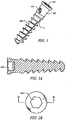
- Fig. 1 illustrates an anchoring member A
- the anchoring member A generally has cancellous screws' features such as a 2-portion shaft comprising an optionally coarse, self-tapping thread 103, designed to anchor in the softer medullary or cancellous bone, and topped by a smooth unthreaded portion 101 that allows it to act as a lag screw.
- the unthreaded upper portion 101 presents an oblique aperture 102 having an angle (for example, of about 25°) with respect to an axial plane of the anchoring member's shaft.
- the proximal end of the anchoring member A has a proximal end socket 104 such that it can be engaged by a fastener like a key, screwdriver, or wrench (see Fig. 2b ).
- the proximal end of the anchoring member A has a Hex (hexagonal) type's proximal end socket 104 such that it can be engaged by a Hex tip fastener like a key or wrench (see Fig. 2b ).
- fastener refers to a tool, such as a wrench, key, or screwdriver, that is employed to insert the corresponding anchor in the bone via the head of the anchor and/or to insert the corresponding locking member in the anchor via the socket 104 of the head of the locking member.
- the socket 104 of the head of the anchor or locking member may be of any shape
- the embodiment presented herein wherein both heads are hexagonal is merely illustrative. That is, the shape of the socket 104 for insertion of the respective fastener in the anchor or locking member may be of any shape, including hexagonal, pentagonal, square, triangular, cross-shaped, plus sign-shaped, linear, star-shaped, and so forth, for example.
- the head of the locking member is smaller than the head of the anchor, although in other embodiments the head of the locking member is the same size as the head of the anchor.
- the socket 104 of the proximal end of the anchor and the socket 104 of the proximal end of the locking member are identical in shape and/or size, whereas in other specific embodiments the socket 104 of the proximal end of the anchor and the socket 104 of the proximal end of the locking member are not identical in shape and/or size.
- Fig. 2 shows a cross-sectional view of the anchoring member ( Fig. 2a ) and a top plan of the proximal end of the anchoring member ( Fig. 2b ).
- the shape of the socket 104 for insertion of the respective fastener in the anchor or locking member may be of any shape, including hexagonal, pentagonal, square, triangular, cross-shaped, plus sign-shaped, linear, star-shaped, and so forth, for example (see below); these may be referred to as slotted, Phillips, Pozidriv, torx, Hex key, Robertson, Tri-Wing, Torq-Set, or Spanner, for example.
- an exemplary hexagonal (Hex) socket In the head 104 of the anchoring member brings the following advantage: a ball end hex key (or wrench) can be used for angulated screwing and insertion, the contact surfaces of the screw are protected from external damage, the tool can be used with a headless screw, there are six contact surfaces between screw and driver, the socket's depth are less prone to stripping, and this room can be used for cannulation, for example.
- a ball end hex key or wrench
- Fig. 3 illustrates the anchoring system 100 comprising the anchoring member A and the locking member L.
- the angle ⁇ between the two members is fixed and set up at 25 degrees in a certain embodiment.
- This angle allows using a standard hex second fastener F2 (wherein F1 fastener refers to the fastener for the anchor and F2 fastener refers to the fastener for the locking member) equipped with an end ball hex end since it can be used with an angulation up to 30 degrees.
- the angle can be set up to another value comprised between 1 to 90 degrees.
- the angle can be 15-25 degrees. Beyond 30 degrees angulation, another embodiment of the second fastener F2 with an inclinable hex tip end may be used (differential inner mechanism).
- Fig. 4 is a schematic cross-sectional plan view of the anchoring system 100.
- a headless locking member L is engaged into an oblique aperture 111 within the exemplary hex-shaped socket 104 of the head of the anchoring member A.
- the surface of the inner wall of the aperture may be threaded, smooth, or rough.
- One end of the aperture is at the proximal head of the anchor, and the opposite end is on one side of the anchor.
- Fig. 5 is a perspective view of an anchoring member holding an exemplary object (plate) P.
- Fig. 6 illustrates the first fastener F1 with its Hex type tip ( 112 ).
- the fastener comprises a head or tip that engages with the socket of the anchor to apply torque by rotating the tip, such as but not limited to a screwdriver, key or wrench.
- the tip is not limited to hex type.
- the second fastener F2 in certain aspects comprises a ball end hex type end to allow screwing of the locking member.
- the second fastener F2 can have the same features as the first fastener F1 when used in a particular embodiment e.g. with an angle ⁇ between the two members equal at 25 degrees, or inferior at 30 degrees at the maximum, in accordance with the working angle (25 to 30 degrees) of such ball end hex tip. In this case, only the size differs from the first fastener F1, the second fastener F2 being thinner than the first fastener F1 in order to be able to slid within the inner socket 104 of the first fastener F1, in particular embodiments
- an angle ⁇ higher than the angle ⁇ , e.g. superior at 30 degrees between the two members A and L, is set up.
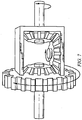
- the second fastener F2 presents an inclinable tip able to match the angle ⁇ and is equipped with an inner mechanism applying the torque in accordance with an oblique transmission of the rotating motion imparted to the handle of the fastener.
- Such mechanism can be but is not limited to a differential, a screw gear, or a set of gears.
- Fig. 7 Illustrates the principle of such mechanism and shows a schematic conceptual view of a differential.
- Such a fastener can be rotated manually or by an electric or other motor.
- Fig. 8a is an enlarged perspective view of the distal end (ball end hex tool) of the fastener.
- the concept by which ball ends slide Into a screw head is known as funnel insertion. Basically, It means that the sides of the ball end direct (funnel) it into place. This allows fast funnel entry, eliminates wasted time even in blind applications, and the full depth engagement reduces "stripping" problems.
- Fig. 8b is an enlarged lateral view of the distal end (ball end hex tool) showing a 25 to 30 degree angle entry to hex.
- neck size decreases, and strength also decreases.
- increasing the strength of a ball-end tool requires a corresponding increase in neck size and decrease in maximum allowable angle.
- Designing the perfect ball-end tool means choosing the Ideal balance between strength and allowable angle.
- Fig. 8c is an example of oblique insertion.
- Fig. 8d is a lateral view of the first fastener F1 engaged within a hex screw.
- Fig. 9 illustrates the three possible designs of the locking member L.
- the locking member L is thinner than the anchoring member A so that it can be slid through the oblique aperture and positioned within the empty room of the hexagonal socket of the anchoring member. Its length can be smaller, equal or bigger than the anchoring member. Its proximal end can be equipped with a head 105 or be wide-mouthed 106 to block within the anchoring member's head, or be headless 107. Whatever the type of the locking member L can be (headed 105, wide-mouthed 106 or headless 107 ), the socket has a hex type shape, in certain embodiments.
- the locking member can be a cortical type screw ( Fig.
- the locking member L can just act as an anti-rotational device and prevent the unscrewing of the anchoring member A In the cortical type design, or be both a blocking system as described above and an additional fastening device intended to secure and reinforce the grip within the medullary bone in the cancellous type design. Moreover, due to its divergent positioning, it brings to the construct a V-shaped design which opposes to pull-out forces. Whatever cancellous or cortical type design be used, the adjunction of a second divergent member (locking member L) advantageously increases both the grip and the purchase within the bone, especially in cancellous and/or osteoporotic bone and therefore opposes to pull-out and secures the fixation of any object to the bone.
- Fig. 10 illustrates various angulation patterns of the interlocking anchor and locking members.
- the proximal end of the anchoring member requires a cavity at Its socket to allow the fastener access to the locking member.
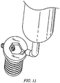
- Fig. 11 illustrates one embodiment of a locking member within an anchoring member, in addition to the respective fastener having a corresponding angulation to the angulation of the locking member within the anchoring member.
- the proximal end of the anchoring member has a cavity that allows insertion of the fastener for the locking member.
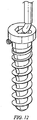
- Fig. 12 illustrates an exemplary embodiment of a fastener and its corresponding locking member within the anchoring member.
- the proximal end of the anchoring member comprises a cavity that allows insertion of the fastener for the locking member.
- the anchor and locking member are coated with antibiotic or other medicine useful upon implantation of an implant on and/or in a bone.
- the surface of the anchor and/or locking member is rough for a better grip within the bone.
- kits of the present invention may include a means for containing the Invention component(s) in close confinement for commercial sale.
- Such containers may Include injection or blow molded plastic containers into which the components are retained, for example.
- the kit may comprise the anchor, locking member, and/or fastener(s). In some cases, all components are sold separate, whereas in other cases all or a subset of components are sold together. Irrespective of the number and/or type of containers, the kits of the invention may also comprise, and/or be packaged with, an instrument other than a fastener(s) of the invention for assisting with placing the anchor/locking member within the body of an animal.
- a variety of anchors, locking members, and/or fasteners may be provided in a kit.
- a variety of lengths, diameters, socket shapes, and/or angles of the corresponding anchors, locking members, and/or fastener(s) may be provided in a kit.
Landscapes
- Health & Medical Sciences (AREA)
- Orthopedic Medicine & Surgery (AREA)
- Life Sciences & Earth Sciences (AREA)
- Surgery (AREA)
- Engineering & Computer Science (AREA)
- Heart & Thoracic Surgery (AREA)
- General Health & Medical Sciences (AREA)
- Biomedical Technology (AREA)
- Veterinary Medicine (AREA)
- Medical Informatics (AREA)
- Molecular Biology (AREA)
- Animal Behavior & Ethology (AREA)
- Nuclear Medicine, Radiotherapy & Molecular Imaging (AREA)
- Public Health (AREA)
- Neurology (AREA)
- General Engineering & Computer Science (AREA)
- Mechanical Engineering (AREA)
- Surgical Instruments (AREA)
- Prostheses (AREA)
Claims (15)
- Système (100), comprenant:une lame osseuse (P) configurée pour être positionnée par rapport à du tissu osseux ;un élément d'ancrage (A) allongé le long d'un premier axe, l'élément d'ancrage (A) incluant une extrémité proximale et une extrémité distale espacée de l'extrémité proximale le long du premier axe, l'extrémité proximale incluant une emboîture (104) configurée pour recevoir au moins une fixation, laquelle est configurée pour appliquer une force de torsion à l'emboîture (104), afin ainsi d'entraîner l'élément d'ancrage (A) dans le tissu osseux, l'extrémité proximale incluant en outre une ouverture (102), laquelle s'étend le long d'un deuxième axe, lequel est oblique par rapport au premier axe, etun élément de verrouillage (L) configuré pour être introduit à travers l'ouverture (102) le long du deuxième axe afin de venir en prise avec le tissu osseux, dans lequel l'élément de verrouillage (L) est allongé le long d'un troisième axe, l'élément de verrouillage incluant une extrémité proximale et une extrémité distale opposée à l'extrémité proximale le long du troisième axe ;dans lequel l'élément d'ancrage (A) est apte à maintenir la lame osseuse (P) par rapport au tissu osseux,caractérisé en ce que l'extrémité proximale de l'élément de verrouillage (L) définit une emboîture d'élément de verrouillage, laquelle est configurée pour recevoir un couple de manière à entraîner l'élément de verrouillage (L) dans le tissu osseux.
- Système selon la revendication 1, dans lequel l'extrémité proximale de l'élément d'ancrage inclut une surface proximale, laquelle est perpendiculaire au premier axe, une ouverture d'emboîture sur la surface proximale, et une paroi interne d'emboîture, laquelle s'étend de la surface proximale vers l'extrémité distale le long du premier axe, dans lequel le deuxième axe s'étend à travers l'ouverture d'emboîture.
- Système selon la revendication 2, dans lequel l'élément d'ancrage définit une surface extérieure, laquelle est espacée du premier axe, dans lequel l'ouverture s'étend de la paroi interne d'emboîture à la surface extérieure le long du deuxième axe.
- Système selon la revendication 3, dans lequel l'extrémité proximale de l'élément d'ancrage est apte à tenir la lame osseuse par rapport au tissu osseux lorsque l'extrémité distale est en prise avec le tissu osseux.
- Système selon l'une quelconque des revendications 1 à 4, dans lequel l'élément de verrouillage est dimensionné de telle sorte que l'élément de verrouillage est configuré pour être introduit à travers l'emboîture dans l'ouverture le long du deuxième axe jusqu'à ce que l'extrémité proximale de l'élément de verrouillage soit assise dans l'ouverture, et l'extrémité distale de l'élément de verrouillage s'étend vers l'extérieur par rapport à la surface extérieure de manière à venir en prise avec le tissu osseux.
- Système selon l'une quelconque des revendications 1 à 5, le système comprenant en outre une première fixation et une seconde fixation, la première fixation incluant une première tête, laquelle est configurée pour venir en prise avec l'emboîture de l'élément d'ancrage, de manière à transmettre une force de torsion à l'élément d'ancrage, et la seconde fixation présente une seconde tête, laquelle est configurée pour venir en prise avec l'emboîture d'élément de verrouillage de manière à transmettre une force de torsion à l'élément de verrouillage.
- Système selon l'une quelconque des revendications 1 à 6, dans lequel l'élément d'ancrage inclut une surface intérieure, la surface intérieure définissant l'ouverture, dans lequel la surface est lisse, rugueuse, ou filetée.
- Système selon l'une quelconque des revendications 1 à 7, dans lequel le premier axe s'étend suivant un angle par rapport au deuxième axe de l'ouverture, dans lequel l'angle est compris entre 1 et 89 degrés.
- Système selon la revendication 8, dans lequel l'angle est compris entre 50 et 75 degrés.
- Système selon la revendication 8, dans lequel l'angle est compris entre 25 et 30 degrés.
- Système selon l'une quelconque des revendications 1 à 10, dans lequel l'emboîture d'élément d'ancrage définit une forme, laquelle est hexagonale, pentagonale, carrée, triangulaire, en forme de croix, en forme de ligne, ou en forme étoilée.
- Kit, comprenant :une lame osseuse (P) configurée pour être positionnée par rapport à du tissu osseux ;une pluralité d'éléments d'ancrage (A), chacun allongé le long d'un premier axe, et présentant une extrémité proximale et une extrémité distale espacée de l'extrémité proximale le long du premier axe, chacune des extrémités proximales incluant une ouverture (102), laquelle s'étend le long d'un deuxième axe, lequel est oblique par rapport au premier axe,
l'extrémité proximale de chacun des éléments d'ancrage (A) incluant une emboîture (104) configurée pour venir en prise avec une fixation et recevoir un couple à partir de la fixation, et l'ouverture (102) étant positionnée dans l'emboîture (104) de telle sorte que l'ouverture (102) est ouverte vers l'emboîture (104), etune pluralité d'éléments de verrouillage (L) présentant chacun une extrémité proximale et une extrémité distale opposée ;dans lequel chacune des ouvertures (102) est apte à une introduction d'un des éléments de verrouillage (L) ;dans lequel chacun des éléments d'ancrage (A) est apte à tenir la lame osseuse (P) par rapport au tissu osseux,caractérisé en ce que l'extrémité proximale de chacun de la pluralité d'éléments de verrouillage (L) inclut une emboîture d'élément de verrouillage, laquelle est configurée pour recevoir un couple de manière à entraîner l'élément de verrouillage respectif (L) dans le tissu osseux. - Kit selon la revendication 12, comprenant en outre au moins une fixation, dans lequel la fixation est apte à s'adapter dans l'emboîture dans l'extrémité proximale d'au moins un de la pluralité d'éléments de verrouillage (L).
- Kit selon la revendication 12, comprenant en outre au moins une fixation, dans lequel la au moins une fixation est apte à adapter soit l'emboîture (104) dans l'extrémité proximale de chacun des éléments d'ancrage (A), soit l'emboîture dans l'extrémité proximale de chacun des éléments de verrouillage (L), ou les deux.
- Kit selon la revendication 12, comprenant en outre des première et seconde fixations, dans lequel la première fixation est apte à adapter l'emboîture (104) dans l'extrémité proximale des éléments d'ancrage (A), et la seconde fixation est apte à adapter l'emboîture dans l'extrémité proximale des éléments de verrouillage (L).
Applications Claiming Priority (3)
| Application Number | Priority Date | Filing Date | Title |
|---|---|---|---|
| US3946408P | 2008-03-26 | 2008-03-26 | |
| PCT/US2009/038376 WO2009120852A2 (fr) | 2008-03-26 | 2009-03-26 | Ancre universelle pour attacher des objets à un tissu osseux |
| EP09724639.1A EP2285299B1 (fr) | 2008-03-26 | 2009-03-26 | Ancre universelle pour attacher des objets à un tissu osseux |
Related Parent Applications (1)
| Application Number | Title | Priority Date | Filing Date |
|---|---|---|---|
| EP09724639.1A Division EP2285299B1 (fr) | 2008-03-26 | 2009-03-26 | Ancre universelle pour attacher des objets à un tissu osseux |
Publications (2)
| Publication Number | Publication Date |
|---|---|
| EP3108834A1 EP3108834A1 (fr) | 2016-12-28 |
| EP3108834B1 true EP3108834B1 (fr) | 2019-05-29 |
Family
ID=41114711
Family Applications (2)
| Application Number | Title | Priority Date | Filing Date |
|---|---|---|---|
| EP16001477.5A Active EP3108834B1 (fr) | 2008-03-26 | 2009-03-26 | Ancre universelle pour fixer des objets à un tissu osseux |
| EP09724639.1A Not-in-force EP2285299B1 (fr) | 2008-03-26 | 2009-03-26 | Ancre universelle pour attacher des objets à un tissu osseux |
Family Applications After (1)
| Application Number | Title | Priority Date | Filing Date |
|---|---|---|---|
| EP09724639.1A Not-in-force EP2285299B1 (fr) | 2008-03-26 | 2009-03-26 | Ancre universelle pour attacher des objets à un tissu osseux |
Country Status (9)
| Country | Link |
|---|---|
| US (2) | US9084646B2 (fr) |
| EP (2) | EP3108834B1 (fr) |
| JP (2) | JP5788787B2 (fr) |
| KR (1) | KR101602153B1 (fr) |
| CN (2) | CN102046105B (fr) |
| BR (1) | BRPI0911290B8 (fr) |
| CA (1) | CA2719699C (fr) |
| CO (1) | CO6331410A2 (fr) |
| WO (1) | WO2009120852A2 (fr) |
Families Citing this family (46)
| Publication number | Priority date | Publication date | Assignee | Title |
|---|---|---|---|---|
| JP5788787B2 (ja) | 2008-03-26 | 2015-10-07 | ジンテス ゲゼルシャフト ミット ベシュレンクテル ハフツング | 目的物を骨組織に取り付ける万能固定装置 |
| US8882838B2 (en) | 2008-06-05 | 2014-11-11 | DePuy Synthes Products, LLC | Articulating disc implant |
| CN102046111A (zh) * | 2008-06-05 | 2011-05-04 | 斯恩蒂斯有限公司 | 铰接的椎间盘植入体 |
| US9017329B2 (en) * | 2008-06-24 | 2015-04-28 | Extremity Medical, Llc | Intramedullary fixation assembly and method of use |
| US8303589B2 (en) | 2008-06-24 | 2012-11-06 | Extremity Medical Llc | Fixation system, an intramedullary fixation assembly and method of use |
| US9289220B2 (en) * | 2008-06-24 | 2016-03-22 | Extremity Medical Llc | Intramedullary fixation assembly and method of use |
| US20110230884A1 (en) * | 2008-06-24 | 2011-09-22 | Adam Mantzaris | Hybrid intramedullary fixation assembly and method of use |
| US8313487B2 (en) | 2008-06-24 | 2012-11-20 | Extremity Medical Llc | Fixation system, an intramedullary fixation assembly and method of use |
| US8343199B2 (en) * | 2008-06-24 | 2013-01-01 | Extremity Medical, Llc | Intramedullary fixation screw, a fixation system, and method of fixation of the subtalar joint |
| US8328806B2 (en) | 2008-06-24 | 2012-12-11 | Extremity Medical, Llc | Fixation system, an intramedullary fixation assembly and method of use |
| US9044282B2 (en) | 2008-06-24 | 2015-06-02 | Extremity Medical Llc | Intraosseous intramedullary fixation assembly and method of use |
| EP2385800B1 (fr) * | 2008-12-05 | 2015-08-19 | Synthes GmbH | Système ancrage-dans-ancrage pour fixation osseuse |
| US9060808B2 (en) | 2008-12-05 | 2015-06-23 | DePuy Synthes Products, Inc. | Anchor-in-anchor system for use in bone fixation |
| AU2011227073B2 (en) * | 2010-03-19 | 2013-09-19 | Josef Gorek | Spinal fixation apparatus and methods |
| KR101885506B1 (ko) * | 2010-05-13 | 2018-08-07 | 신세스 게엠바하 | 뼈 나사 어셈블리 및 이의 이식을 위한 기구 |
| JP5769801B2 (ja) * | 2010-06-09 | 2015-08-26 | ジンテス ゲゼルシャフト ミット ベシュレンクテル ハフツング | 骨固定において使用するためのアンカ・イン・アンカシステム |
| ES2552254T3 (es) | 2010-11-17 | 2015-11-26 | Hyprevention | Dispositivo implantable para el tratamiento preventivo o curativo de fracturas del fémur, ancilar asociado |
| CH705356A2 (de) * | 2011-08-11 | 2013-02-15 | Regenhu Ag | Körper mit einer Grundstruktur aus Knochenersatzmaterial und Verfahren zur Herstellung. |
| CN102835998A (zh) * | 2012-08-17 | 2012-12-26 | 苏州瑞华医院有限公司 | 一种治疗肱骨外科颈骨折的新型内固定锁定接骨板 |
| BR112015003783B1 (pt) | 2012-08-22 | 2021-06-01 | Synthes Gmbh | Ligação configurada para uso em um sistema âncora-em-âncora e sistema âncora-em- âncora |
| US20150005856A1 (en) * | 2013-06-27 | 2015-01-01 | Boston Scientific Neuromodulation Corporation | Lead anchors and systems and methods using the lead anchors |
| BR112016026276B1 (pt) * | 2014-05-09 | 2022-02-01 | Abanza Tecnomed, S.L. | Dispositivo para aprisionar a extremidade de pelo menos um fascículo de material macio em um túnel de osso |
| EP3209243A4 (fr) * | 2014-08-28 | 2018-08-01 | Cochlear Limited | Dispositif de fixation osseuse pour prothèse médicale |
| US9649133B2 (en) * | 2014-11-11 | 2017-05-16 | Intrepid Orthopedics | Supplemental fixation screw |
| US9855132B2 (en) * | 2015-01-30 | 2018-01-02 | Arthrex, Inc. | Ligament fixation device and method |
| CN104688285B (zh) * | 2015-03-27 | 2017-09-29 | 王谦 | 肩关节缝合自锁结构 |
| GR20150100144A (el) * | 2015-03-30 | 2016-10-20 | Γεωργιος Κωνσταντινου Κωστακης | Οδοντικο εμφυτευμα με βελτιωμενη σταθεροτητα και οστεοενσωματωση |
| US9636498B2 (en) | 2015-08-03 | 2017-05-02 | Boston Scientific Neuromodulation Corporation | Lead anchor with a wedge and systems using the lead anchor |
| WO2017070335A1 (fr) * | 2015-10-20 | 2017-04-27 | Implant Direct Sybron International Llc | Vis et outil d'entraînement pour procédures dentaires |
| WO2017151438A1 (fr) | 2016-02-29 | 2017-09-08 | Boston Scientific Neuromodulation Corporation | Point d'ancrage de conducteur électrique pour système de stimulation électrique |
| US10369354B2 (en) | 2016-05-17 | 2019-08-06 | Boston Scientific Neuromodulation Corporation | Systems and method for anchoring a lead for neurostimulation of a target anatomy |
| CN105997218A (zh) * | 2016-06-29 | 2016-10-12 | 江苏艾迪尔医疗科技股份有限公司 | 肱骨倒置髓内钉 |
| ES2676437B1 (es) * | 2017-01-19 | 2019-04-29 | Delgado Oscar Ruesga | Guía bifásica de precisión y su método para fijar en un hueso maxilar de baja altura un trípode con función de implante dental corto. |
| US10709886B2 (en) | 2017-02-28 | 2020-07-14 | Boston Scientific Neuromodulation Corporation | Electrical stimulation leads and systems with elongate anchoring elements and methods of making and using |
| US10835739B2 (en) | 2017-03-24 | 2020-11-17 | Boston Scientific Neuromodulation Corporation | Electrical stimulation leads and systems with elongate anchoring elements and methods of making and using |
| US10779867B2 (en) | 2017-04-06 | 2020-09-22 | Extremity Medical Llc | Orthopedic plate with modular peg and compression screw |
| US10857351B2 (en) | 2017-04-28 | 2020-12-08 | Boston Scientific Neuromodulation Corporation | Lead anchors for electrical stimulation leads and systems and methods of making and using |
| CH716094B1 (de) * | 2018-02-28 | 2023-01-13 | Camlog Biotechnologies Gmbh | Winkelversetzte Schraubeneingriffnahme. |
| WO2020142213A1 (fr) | 2019-01-02 | 2020-07-09 | In Queue Innovations, Llc | Système de fixation osseuse et procédés d'utilisation |
| US12185997B2 (en) | 2019-08-14 | 2025-01-07 | K2M, Inc. | Pedicle fixation system |
| US12137950B2 (en) * | 2019-10-09 | 2024-11-12 | Kaj Klaue | Bone nail |
| CN113662647A (zh) * | 2020-05-15 | 2021-11-19 | 北京中安泰华科技有限公司 | 一种锁骨自动加压带锁髓内针 |
| US12458421B2 (en) * | 2020-12-18 | 2025-11-04 | DePuy Synthes Products, Inc. | Screw-in-screw bone fixation system |
| US12327486B1 (en) * | 2021-03-19 | 2025-06-10 | HIMM Holdings | Modular mammalian infant head model for oral examination training |
| CN114305636A (zh) * | 2022-01-10 | 2022-04-12 | 航天中心医院 | 髌骨骨折钉缆锁定装置 |
| USD1097157S1 (en) * | 2023-03-03 | 2025-10-07 | Abanza Tecnomed, S.L. | Medical implant |
Family Cites Families (126)
| Publication number | Priority date | Publication date | Assignee | Title |
|---|---|---|---|---|
| US928997A (en) * | 1908-07-07 | 1909-07-27 | Emanuel Mueller | Lock-screw. |
| US1518119A (en) * | 1922-08-05 | 1924-12-02 | Aseptic Service Company | Locked fastening |
| GB303708A (en) * | 1928-04-27 | 1929-01-10 | Frank Harold Clause | Improvements in or relating to means for securing in position screws, nails or the like |
| US3295579A (en) * | 1965-03-08 | 1967-01-03 | Allis Chalmers Mfg Co | Lock bolt |
| US3474537A (en) * | 1965-10-19 | 1969-10-28 | Robert W Christensen | Dental prosthetic appliance |
| US3579831A (en) * | 1969-03-05 | 1971-05-25 | Irving J Stevens | Bone implant |
| JPS54118566U (fr) * | 1978-02-07 | 1979-08-20 | ||
| JPS54118566A (en) | 1978-03-06 | 1979-09-14 | Nippon Electric Co | Method of producing laminated ceramic capacitor |
| US4338835A (en) * | 1980-01-24 | 1982-07-13 | Leon Simons | Recessed head fastener and driver therefor |
| JPS6114484Y2 (fr) * | 1981-02-12 | 1986-05-07 | ||
| DE3124059A1 (de) | 1981-06-18 | 1983-01-05 | Mecron Medizinische Produkte Gmbh, 1000 Berlin | Nagel zum fixieren von oberschenkelbruechen |
| DE3312959A1 (de) * | 1983-04-11 | 1984-10-11 | Erich 8217 Grassau Stabenau | Sicherung fuer eine holzschraube |
| EP0176728B1 (fr) * | 1984-09-04 | 1989-07-26 | Humboldt-Universität zu Berlin | Prothèse pour disques intervertébraux |
| US4754749A (en) * | 1986-04-29 | 1988-07-05 | Tsou Paul M | Surgical screw with counter-rotation prevention means |
| US4828562A (en) * | 1988-02-04 | 1989-05-09 | Pfizer Hospital Products Group, Inc. | Anterior cruciate ligament prosthesis |
| US5038978A (en) * | 1989-11-13 | 1991-08-13 | B&G Plastics, Inc. | Hanger and display support combined therewith |
| US5140877A (en) * | 1990-12-14 | 1992-08-25 | John Sloan | Hexagonal wrench |
| US5797918A (en) * | 1991-12-13 | 1998-08-25 | David A. McGuire | Flexible surgical screwdriver and methods of arthroscopic ligament reconstruction |
| US5251521A (en) | 1992-01-31 | 1993-10-12 | Bondhus Corporation | TORX-compatible elliptical driver |
| US5207529A (en) * | 1992-06-29 | 1993-05-04 | General Motors Corporation | Fastening device |
| DE59310121D1 (de) * | 1992-11-02 | 2000-12-28 | Sulzer Orthopaedie Ag Baar | Verankerung für ein künstliches Band |
| US5370662A (en) | 1993-06-23 | 1994-12-06 | Kevin R. Stone | Suture anchor assembly |
| FR2709412B1 (fr) * | 1993-09-01 | 1995-11-24 | Tornier Sa | Vis pour fixateur lombo-sacré. |
| FR2718014A1 (fr) | 1994-04-05 | 1995-10-06 | Chagneau Francis | Dispositif d'ancrage par vis ou pointes d'une cupule prothétique. |
| US5443469A (en) * | 1994-05-02 | 1995-08-22 | Smith; Aubrey L. | Intramedullary reaming tissue protection guard |
| GB9411693D0 (en) | 1994-06-10 | 1994-08-03 | Matthews Michael G | Surgical intramedullary nail for stabilisation of condylar and supracondylar fractures |
| US5976139A (en) | 1996-07-17 | 1999-11-02 | Bramlet; Dale G. | Surgical fastener assembly |
| AU1997797A (en) | 1996-05-31 | 1997-12-04 | Acromed Corporation | An apparatus comprising a plate and a fastener for connecting the plate to a bone portion |
| US5993463A (en) * | 1997-05-15 | 1999-11-30 | Regents Of The University Of Minnesota | Remote actuation of trajectory guide |
| AU731976B2 (en) * | 1997-06-02 | 2001-04-12 | Jeannette M. D. Martello | Soft tissue securing anchor |
| US5984681A (en) * | 1997-09-02 | 1999-11-16 | Huang; Barney K. | Dental implant and method of implanting |
| US6270499B1 (en) * | 1997-10-20 | 2001-08-07 | Synthes (U.S.A.) | Bone fixation device |
| US5899941A (en) * | 1997-12-09 | 1999-05-04 | Chubu Bearing Kabushiki Kaisha | Artificial intervertebral disk |
| SE510973C2 (sv) | 1998-03-16 | 1999-07-19 | Scandimed International Ab | Instrument för reposition och fixation av handledsbrott |
| US6013078A (en) * | 1998-08-19 | 2000-01-11 | Lin; Chin | Securing device for bone fastener |
| US6113637A (en) * | 1998-10-22 | 2000-09-05 | Sofamor Danek Holdings, Inc. | Artificial intervertebral joint permitting translational and rotational motion |
| JP4167398B2 (ja) | 1998-12-23 | 2008-10-15 | ネナド セシック, | 長骨の骨接合のための骨幹方向髄内ネジ |
| DE19938916A1 (de) | 1999-05-18 | 2001-02-22 | Merete Man Gmbh | Fraktur-Knochenschraube |
| US6221074B1 (en) | 1999-06-10 | 2001-04-24 | Orthodyne, Inc. | Femoral intramedullary rod system |
| FR2802799B1 (fr) * | 1999-12-23 | 2002-08-16 | Depuy France | Ensemble de prothese d'epaule |
| JP3383257B2 (ja) | 2000-03-10 | 2003-03-04 | 株式会社ロバート・リード商会 | ロッド固定装置 |
| US6235033B1 (en) | 2000-04-19 | 2001-05-22 | Synthes (Usa) | Bone fixation assembly |
| AU6197901A (en) * | 2000-05-25 | 2001-12-03 | Lionel C Sevrain | Anchoring system for fixing objects to bones |
| US6409730B1 (en) | 2000-05-31 | 2002-06-25 | Synthes (Usa) | Humeral spiral blade |
| US6629998B1 (en) | 2000-08-23 | 2003-10-07 | Chih-I Lin | Intervertebral retrieval device |
| US6849093B2 (en) * | 2001-03-09 | 2005-02-01 | Gary K. Michelson | Expansion constraining member adapted for use with an expandable interbody spinal fusion implant and method for use thereof |
| US6443954B1 (en) | 2001-04-24 | 2002-09-03 | Dale G. Bramlet | Femoral nail intramedullary system |
| US6524314B1 (en) | 2001-08-24 | 2003-02-25 | John C. Dean | Interlocking intramedullary nail |
| US6835197B2 (en) | 2001-10-17 | 2004-12-28 | Christoph Andreas Roth | Bone fixation system |
| GB2381197A (en) * | 2001-10-25 | 2003-04-30 | Corin Surgical Ltd | A surgical implant |
| US7094242B2 (en) | 2001-10-31 | 2006-08-22 | K2M, Inc. | Polyaxial drill guide |
| US6467919B1 (en) * | 2001-11-02 | 2002-10-22 | Gentex Corporation | Mirror with split ball mount and hold-open device |
| US20040019353A1 (en) | 2002-02-01 | 2004-01-29 | Freid James M. | Spinal plate system for stabilizing a portion of a spine |
| AR038680A1 (es) | 2002-02-19 | 2005-01-26 | Synthes Ag | Implante intervertebral |
| US6681662B2 (en) | 2002-03-01 | 2004-01-27 | Bondhus Corporation | Tool with fastener engaging member |
| GB2407510B (en) | 2002-07-22 | 2006-06-28 | Acumed Llc | Bone fusion system |
| JP4210647B2 (ja) * | 2002-09-02 | 2009-01-21 | ジンテーズ ゲゼルシャフト ミト ベシュレンクテル ハフツング | 3部から成る関節を有する椎間インプラント |
| US6974479B2 (en) * | 2002-12-10 | 2005-12-13 | Sdgi Holdings, Inc. | System and method for blocking and/or retaining a prosthetic spinal implant |
| FR2848408B1 (fr) * | 2002-12-17 | 2005-08-19 | Vitatech | Dispositif a plaque anterieure pour maintien du rachis |
| US6908484B2 (en) * | 2003-03-06 | 2005-06-21 | Spinecore, Inc. | Cervical disc replacement |
| BR0318151A (pt) * | 2003-03-07 | 2006-02-21 | Synthes Ag | parafuso de travamento para uma garra intramedular |
| US7445125B2 (en) * | 2003-05-19 | 2008-11-04 | Harvest Technologies Corporation | Method and apparatus for separating fluid components |
| KR101089581B1 (ko) * | 2003-05-27 | 2011-12-05 | 호야 가부시키가이샤 | 수술기구 |
| DE20309481U1 (de) | 2003-06-20 | 2003-09-04 | stryker Trauma GmbH, 24232 Schönkirchen | Vorrichtung zum lagerichtigen Einbringen eines Führungsdrahtes für ein Bohrwerkzeug in einen Knochen |
| DE10330698B4 (de) * | 2003-07-08 | 2005-05-25 | Aesculap Ag & Co. Kg | Zwischenwirbelimplantat |
| US7004629B2 (en) * | 2003-07-26 | 2006-02-28 | Arthur Joseph Shrader | Method and apparatus for hanging a resealable bag |
| US20060229729A1 (en) | 2003-08-05 | 2006-10-12 | Gordon Charles R | Expandable intervertebral implant for use with instrument |
| DE20321552U1 (de) | 2003-08-26 | 2007-12-27 | Synthes Gmbh | Knochenplatte |
| US20050055024A1 (en) | 2003-09-08 | 2005-03-10 | James Anthony H. | Orthopaedic implant and screw assembly |
| DE20314297U1 (de) * | 2003-09-12 | 2003-11-20 | AlloCon GmbH, 42929 Wermelskirchen | Knochenschraube |
| US20050107791A1 (en) * | 2003-11-14 | 2005-05-19 | Manderson Easton L. | Intramedullary locked compression screw for stabiliziation and union of complex ankle and subtalar deformities |
| US8574268B2 (en) | 2004-01-26 | 2013-11-05 | DePuy Synthes Product, LLC | Highly-versatile variable-angle bone plate system |
| US7637928B2 (en) | 2004-01-26 | 2009-12-29 | Synthes Usa, Llc | Variable angle locked bone fixation system |
| WO2006016384A1 (fr) | 2004-08-12 | 2006-02-16 | Sintea Biotech S.P.A. | Prothese discale |
| US8470037B2 (en) * | 2004-08-18 | 2013-06-25 | Covidien Lp | Method and apparatus for reconstructing a ligament |
| US7780731B2 (en) | 2004-11-26 | 2010-08-24 | Spine Solutions, Inc. | Intervertebral implant |
| EP1639953B1 (fr) | 2004-09-27 | 2008-05-21 | ORTHOFIX S.r.l. | Clou intramédullaire pour le traitement de fractures proximales du fémur |
| ITRE20040143A1 (it) | 2004-11-19 | 2005-02-19 | Gian Luca Rovesti | Vite chirurgica con sistema di bloccaggio preventivo dell'allentamento spontaneo |
| EP1855620A1 (fr) * | 2005-01-11 | 2007-11-21 | Barry T. Bickley | Ancrage de greffon |
| US8097036B2 (en) | 2005-05-02 | 2012-01-17 | Seaspine, Inc. | Motion restoring intervertebral device |
| FR2885294B1 (fr) * | 2005-05-03 | 2008-04-04 | Jerome Levieux | Prothese de disque intervertebral |
| US20080221623A1 (en) * | 2005-10-17 | 2008-09-11 | Gooch Hubert L | Systems and Methods for the Medical Treatment of Structural Tissue |
| US20080221624A1 (en) * | 2005-10-17 | 2008-09-11 | Gooch Hubert L | Systems and Methods for the Medical Treatment of Structural Tissue |
| CN101340851B (zh) | 2005-10-21 | 2012-12-12 | 精密医疗责任有限公司 | 具有锁定孔的矫形棒 |
| US20070123874A1 (en) | 2005-10-31 | 2007-05-31 | Czartoski Timothy J | Multiple purpose nail with oblique openings |
| US20070156145A1 (en) | 2005-12-30 | 2007-07-05 | Kentomia, Llc | Therapeutic constructions, spinal plates, cervical plates, hooks and screws |
| US8252058B2 (en) * | 2006-02-16 | 2012-08-28 | Amedica Corporation | Spinal implant with elliptical articulatory interface |
| US20100305704A1 (en) | 2006-02-27 | 2010-12-02 | Synthes Gmbh | Intervertebral implant with fixation geometry |
| US7641675B2 (en) * | 2006-03-08 | 2010-01-05 | Warsaw Orthopedic, Inc. | Flexible bone plates and methods for dynamic spinal stabilization |
| US20080033438A1 (en) * | 2006-08-04 | 2008-02-07 | Roy Frizzell | Cervical Saddle Plate |
| US8303590B2 (en) | 2007-01-26 | 2012-11-06 | Ebi, Llc | Lockable intramedullary fixation device |
| EP2136731B1 (fr) * | 2007-03-23 | 2017-05-03 | Heraeus Kulzer GmbH | Tournevis et élément de vis adapté à celui-ci |
| US20080249569A1 (en) | 2007-04-03 | 2008-10-09 | Warsaw Orthopedic, Inc. | Implant Face Plates |
| FR2916624B1 (fr) | 2007-05-29 | 2009-08-21 | Small Bone Innovations Interna | Vis a os, notamment d'osteosynthese |
| WO2009058969A1 (fr) | 2007-10-30 | 2009-05-07 | Synthes (U.S.A.) | Lame osseuse verrouillée à angle variable |
| FR2923157B1 (fr) | 2007-11-05 | 2010-09-17 | Hpi | Prothese de disques intervertebraux |
| JP5788787B2 (ja) | 2008-03-26 | 2015-10-07 | ジンテス ゲゼルシャフト ミット ベシュレンクテル ハフツング | 目的物を骨組織に取り付ける万能固定装置 |
| CN102046111A (zh) | 2008-06-05 | 2011-05-04 | 斯恩蒂斯有限公司 | 铰接的椎间盘植入体 |
| US8882838B2 (en) | 2008-06-05 | 2014-11-11 | DePuy Synthes Products, LLC | Articulating disc implant |
| EP2133034B1 (fr) * | 2008-06-13 | 2011-12-28 | Orthofix S.r.l. | Broche intramédullaire à insérer dans un os long fracturé |
| US8328806B2 (en) * | 2008-06-24 | 2012-12-11 | Extremity Medical, Llc | Fixation system, an intramedullary fixation assembly and method of use |
| US20110125153A1 (en) * | 2008-06-24 | 2011-05-26 | Jeff Tyber | Intramedullary fixation assembly and method of use |
| US8303589B2 (en) * | 2008-06-24 | 2012-11-06 | Extremity Medical Llc | Fixation system, an intramedullary fixation assembly and method of use |
| US9017329B2 (en) * | 2008-06-24 | 2015-04-28 | Extremity Medical, Llc | Intramedullary fixation assembly and method of use |
| US8343199B2 (en) * | 2008-06-24 | 2013-01-01 | Extremity Medical, Llc | Intramedullary fixation screw, a fixation system, and method of fixation of the subtalar joint |
| US20110230884A1 (en) | 2008-06-24 | 2011-09-22 | Adam Mantzaris | Hybrid intramedullary fixation assembly and method of use |
| US8313487B2 (en) * | 2008-06-24 | 2012-11-20 | Extremity Medical Llc | Fixation system, an intramedullary fixation assembly and method of use |
| US9044282B2 (en) * | 2008-06-24 | 2015-06-02 | Extremity Medical Llc | Intraosseous intramedullary fixation assembly and method of use |
| US20100121325A1 (en) * | 2008-06-24 | 2010-05-13 | Jeff Tyber | Hybrid intramedullary fixation assembly and method of use |
| US20090326545A1 (en) * | 2008-06-26 | 2009-12-31 | Amedica Corporation | Systems and methods for inserting a bone anchor without a pilot hole |
| WO2010017357A1 (fr) | 2008-08-07 | 2010-02-11 | K2M, Inc. | Ensemble de vis à os |
| US8328872B2 (en) | 2008-09-02 | 2012-12-11 | Globus Medical, Inc. | Intervertebral fusion implant |
| US8231625B2 (en) | 2008-09-03 | 2012-07-31 | The Cleveland Clinic Foundation | Modular bone fixation device for treatment of fractures and related methods |
| EP2385800B1 (fr) | 2008-12-05 | 2015-08-19 | Synthes GmbH | Système ancrage-dans-ancrage pour fixation osseuse |
| US9060808B2 (en) * | 2008-12-05 | 2015-06-23 | DePuy Synthes Products, Inc. | Anchor-in-anchor system for use in bone fixation |
| US20100160924A1 (en) * | 2008-12-23 | 2010-06-24 | Howmedica Osteonics Corp. | Drill guide with angle verification |
| CN101507652A (zh) | 2009-03-20 | 2009-08-19 | 周志海 | 膝关节入路髓内钉 |
| WO2010124205A1 (fr) | 2009-04-24 | 2010-10-28 | Synthes Usa, Llc | Vis multiplexées |
| EP2476387B1 (fr) * | 2009-07-01 | 2016-07-20 | Synthes GmbH | Clou intramédullaire et mécanisme de verrouillage de vis faisant saillie |
| EP2477566B1 (fr) | 2009-09-14 | 2017-03-22 | Synthes GmbH | Plaque de compression à angle variable |
| US8486116B2 (en) | 2010-01-08 | 2013-07-16 | Biomet Manufacturing Ring Corporation | Variable angle locking screw |
| AU2011227073B2 (en) * | 2010-03-19 | 2013-09-19 | Josef Gorek | Spinal fixation apparatus and methods |
| KR101885506B1 (ko) * | 2010-05-13 | 2018-08-07 | 신세스 게엠바하 | 뼈 나사 어셈블리 및 이의 이식을 위한 기구 |
| JP5769801B2 (ja) | 2010-06-09 | 2015-08-26 | ジンテス ゲゼルシャフト ミット ベシュレンクテル ハフツング | 骨固定において使用するためのアンカ・イン・アンカシステム |
| EP2460484A1 (fr) | 2010-12-01 | 2012-06-06 | FACET-LINK Inc. | Agencement de fixation de vis d'os à angle variable |
| EP2667798B1 (fr) | 2011-01-28 | 2015-07-29 | Synthes GmbH | Systèmes guide-alésoir |
-
2009
- 2009-03-26 JP JP2011502049A patent/JP5788787B2/ja not_active Expired - Fee Related
- 2009-03-26 US US12/934,196 patent/US9084646B2/en not_active Expired - Fee Related
- 2009-03-26 CN CN200980118021.0A patent/CN102046105B/zh not_active Expired - Fee Related
- 2009-03-26 BR BRPI0911290A patent/BRPI0911290B8/pt not_active IP Right Cessation
- 2009-03-26 CA CA2719699A patent/CA2719699C/fr active Active
- 2009-03-26 EP EP16001477.5A patent/EP3108834B1/fr active Active
- 2009-03-26 CN CN201410086633.9A patent/CN104068925B/zh not_active Expired - Fee Related
- 2009-03-26 WO PCT/US2009/038376 patent/WO2009120852A2/fr not_active Ceased
- 2009-03-26 EP EP09724639.1A patent/EP2285299B1/fr not_active Not-in-force
- 2009-03-26 KR KR1020107023629A patent/KR101602153B1/ko not_active Expired - Fee Related
-
2010
- 2010-10-26 CO CO10132564A patent/CO6331410A2/es active IP Right Grant
-
2015
- 2015-06-16 US US14/740,904 patent/US10045804B2/en active Active
- 2015-07-30 JP JP2015150310A patent/JP6258269B2/ja not_active Expired - Fee Related
Non-Patent Citations (1)
| Title |
|---|
| None * |
Also Published As
| Publication number | Publication date |
|---|---|
| EP2285299B1 (fr) | 2016-07-06 |
| CN104068925B (zh) | 2017-07-14 |
| JP6258269B2 (ja) | 2018-01-10 |
| KR101602153B1 (ko) | 2016-03-10 |
| CN102046105B (zh) | 2014-04-09 |
| US20110022066A1 (en) | 2011-01-27 |
| WO2009120852A2 (fr) | 2009-10-01 |
| JP2015192911A (ja) | 2015-11-05 |
| US9084646B2 (en) | 2015-07-21 |
| CN104068925A (zh) | 2014-10-01 |
| CA2719699C (fr) | 2018-05-15 |
| WO2009120852A3 (fr) | 2009-12-23 |
| JP5788787B2 (ja) | 2015-10-07 |
| BRPI0911290A2 (pt) | 2015-09-29 |
| JP2011517591A (ja) | 2011-06-16 |
| KR20110000660A (ko) | 2011-01-04 |
| EP2285299A2 (fr) | 2011-02-23 |
| CN102046105A (zh) | 2011-05-04 |
| CA2719699A1 (fr) | 2009-10-01 |
| US10045804B2 (en) | 2018-08-14 |
| EP2285299A4 (fr) | 2014-07-30 |
| US20160100871A1 (en) | 2016-04-14 |
| EP3108834A1 (fr) | 2016-12-28 |
| BRPI0911290B8 (pt) | 2021-06-22 |
| BRPI0911290B1 (pt) | 2020-02-11 |
| CO6331410A2 (es) | 2011-10-20 |
Similar Documents
| Publication | Publication Date | Title |
|---|---|---|
| EP3108834B1 (fr) | Ancre universelle pour fixer des objets à un tissu osseux | |
| US7325470B2 (en) | Self-centering screw and retaining screw driver for use in surgery | |
| US9615869B2 (en) | Bone screw | |
| US6471707B1 (en) | Bone screw having bioresorbable proximal shaft portion | |
| US7824428B2 (en) | System to be used with an implanting tool | |
| EP2734137B1 (fr) | Vis à os amovible à incision minimale | |
| US8617225B2 (en) | Spline drive for threaded post-type bone anchors | |
| US7637929B2 (en) | Self-drilling bone screw | |
| US20050149027A1 (en) | Bone screw retaining system | |
| US20070270859A1 (en) | Orthopedic screw with break away drive | |
| KR20040093388A (ko) | 풀릴 수 있는 나삿니를 가지는 뼈 고정 부재 | |
| EP1868516A2 (fr) | Elements de fixation chirurgicaux a expansion | |
| AU2007296739A1 (en) | Hybrid bone fixation apparatus | |
| JP2000515396A (ja) | ねじ山つき座金 | |
| US20150342656A1 (en) | Fracture reduction structure | |
| WO2013092197A1 (fr) | Vis chirurgicales avec enveloppe osseuse |
Legal Events
| Date | Code | Title | Description |
|---|---|---|---|
| PUAI | Public reference made under article 153(3) epc to a published international application that has entered the european phase |
Free format text: ORIGINAL CODE: 0009012 |
|
| STAA | Information on the status of an ep patent application or granted ep patent |
Free format text: STATUS: REQUEST FOR EXAMINATION WAS MADE |
|
| 17P | Request for examination filed |
Effective date: 20160704 |
|
| AC | Divisional application: reference to earlier application |
Ref document number: 2285299 Country of ref document: EP Kind code of ref document: P |
|
| AK | Designated contracting states |
Kind code of ref document: A1 Designated state(s): AT BE BG CH CY CZ DE DK EE ES FI FR GB GR HR HU IE IS IT LI LT LU LV MC MK MT NL NO PL PT RO SE SI SK TR |
|
| GRAP | Despatch of communication of intention to grant a patent |
Free format text: ORIGINAL CODE: EPIDOSNIGR1 |
|
| STAA | Information on the status of an ep patent application or granted ep patent |
Free format text: STATUS: GRANT OF PATENT IS INTENDED |
|
| RIC1 | Information provided on ipc code assigned before grant |
Ipc: A61B 17/86 20060101AFI20180629BHEP Ipc: F16B 39/04 20060101ALI20180629BHEP |
|
| INTG | Intention to grant announced |
Effective date: 20180807 |
|
| GRAJ | Information related to disapproval of communication of intention to grant by the applicant or resumption of examination proceedings by the epo deleted |
Free format text: ORIGINAL CODE: EPIDOSDIGR1 |
|
| STAA | Information on the status of an ep patent application or granted ep patent |
Free format text: STATUS: REQUEST FOR EXAMINATION WAS MADE |
|
| GRAP | Despatch of communication of intention to grant a patent |
Free format text: ORIGINAL CODE: EPIDOSNIGR1 |
|
| STAA | Information on the status of an ep patent application or granted ep patent |
Free format text: STATUS: GRANT OF PATENT IS INTENDED |
|
| INTC | Intention to grant announced (deleted) | ||
| INTG | Intention to grant announced |
Effective date: 20181221 |
|
| GRAS | Grant fee paid |
Free format text: ORIGINAL CODE: EPIDOSNIGR3 |
|
| GRAA | (expected) grant |
Free format text: ORIGINAL CODE: 0009210 |
|
| STAA | Information on the status of an ep patent application or granted ep patent |
Free format text: STATUS: THE PATENT HAS BEEN GRANTED |
|
| AC | Divisional application: reference to earlier application |
Ref document number: 2285299 Country of ref document: EP Kind code of ref document: P |
|
| AK | Designated contracting states |
Kind code of ref document: B1 Designated state(s): AT BE BG CH CY CZ DE DK EE ES FI FR GB GR HR HU IE IS IT LI LT LU LV MC MK MT NL NO PL PT RO SE SI SK TR |
|
| REG | Reference to a national code |
Ref country code: GB Ref legal event code: FG4D |
|
| REG | Reference to a national code |
Ref country code: CH Ref legal event code: EP |
|
| REG | Reference to a national code |
Ref country code: AT Ref legal event code: REF Ref document number: 1137798 Country of ref document: AT Kind code of ref document: T Effective date: 20190615 |
|
| REG | Reference to a national code |
Ref country code: DE Ref legal event code: R096 Ref document number: 602009058587 Country of ref document: DE |
|
| REG | Reference to a national code |
Ref country code: IE Ref legal event code: FG4D |
|
| REG | Reference to a national code |
Ref country code: NL Ref legal event code: MP Effective date: 20190529 |
|
| REG | Reference to a national code |
Ref country code: LT Ref legal event code: MG4D |
|
| PG25 | Lapsed in a contracting state [announced via postgrant information from national office to epo] |
Ref country code: ES Free format text: LAPSE BECAUSE OF FAILURE TO SUBMIT A TRANSLATION OF THE DESCRIPTION OR TO PAY THE FEE WITHIN THE PRESCRIBED TIME-LIMIT Effective date: 20190529 Ref country code: LT Free format text: LAPSE BECAUSE OF FAILURE TO SUBMIT A TRANSLATION OF THE DESCRIPTION OR TO PAY THE FEE WITHIN THE PRESCRIBED TIME-LIMIT Effective date: 20190529 Ref country code: PT Free format text: LAPSE BECAUSE OF FAILURE TO SUBMIT A TRANSLATION OF THE DESCRIPTION OR TO PAY THE FEE WITHIN THE PRESCRIBED TIME-LIMIT Effective date: 20190930 Ref country code: HR Free format text: LAPSE BECAUSE OF FAILURE TO SUBMIT A TRANSLATION OF THE DESCRIPTION OR TO PAY THE FEE WITHIN THE PRESCRIBED TIME-LIMIT Effective date: 20190529 Ref country code: NO Free format text: LAPSE BECAUSE OF FAILURE TO SUBMIT A TRANSLATION OF THE DESCRIPTION OR TO PAY THE FEE WITHIN THE PRESCRIBED TIME-LIMIT Effective date: 20190829 Ref country code: SE Free format text: LAPSE BECAUSE OF FAILURE TO SUBMIT A TRANSLATION OF THE DESCRIPTION OR TO PAY THE FEE WITHIN THE PRESCRIBED TIME-LIMIT Effective date: 20190529 Ref country code: FI Free format text: LAPSE BECAUSE OF FAILURE TO SUBMIT A TRANSLATION OF THE DESCRIPTION OR TO PAY THE FEE WITHIN THE PRESCRIBED TIME-LIMIT Effective date: 20190529 |
|
| PG25 | Lapsed in a contracting state [announced via postgrant information from national office to epo] |
Ref country code: LV Free format text: LAPSE BECAUSE OF FAILURE TO SUBMIT A TRANSLATION OF THE DESCRIPTION OR TO PAY THE FEE WITHIN THE PRESCRIBED TIME-LIMIT Effective date: 20190529 Ref country code: BG Free format text: LAPSE BECAUSE OF FAILURE TO SUBMIT A TRANSLATION OF THE DESCRIPTION OR TO PAY THE FEE WITHIN THE PRESCRIBED TIME-LIMIT Effective date: 20190829 Ref country code: GR Free format text: LAPSE BECAUSE OF FAILURE TO SUBMIT A TRANSLATION OF THE DESCRIPTION OR TO PAY THE FEE WITHIN THE PRESCRIBED TIME-LIMIT Effective date: 20190830 |
|
| REG | Reference to a national code |
Ref country code: AT Ref legal event code: MK05 Ref document number: 1137798 Country of ref document: AT Kind code of ref document: T Effective date: 20190529 |
|
| PG25 | Lapsed in a contracting state [announced via postgrant information from national office to epo] |
Ref country code: SK Free format text: LAPSE BECAUSE OF FAILURE TO SUBMIT A TRANSLATION OF THE DESCRIPTION OR TO PAY THE FEE WITHIN THE PRESCRIBED TIME-LIMIT Effective date: 20190529 Ref country code: CZ Free format text: LAPSE BECAUSE OF FAILURE TO SUBMIT A TRANSLATION OF THE DESCRIPTION OR TO PAY THE FEE WITHIN THE PRESCRIBED TIME-LIMIT Effective date: 20190529 Ref country code: DK Free format text: LAPSE BECAUSE OF FAILURE TO SUBMIT A TRANSLATION OF THE DESCRIPTION OR TO PAY THE FEE WITHIN THE PRESCRIBED TIME-LIMIT Effective date: 20190529 Ref country code: NL Free format text: LAPSE BECAUSE OF FAILURE TO SUBMIT A TRANSLATION OF THE DESCRIPTION OR TO PAY THE FEE WITHIN THE PRESCRIBED TIME-LIMIT Effective date: 20190529 Ref country code: RO Free format text: LAPSE BECAUSE OF FAILURE TO SUBMIT A TRANSLATION OF THE DESCRIPTION OR TO PAY THE FEE WITHIN THE PRESCRIBED TIME-LIMIT Effective date: 20190529 Ref country code: EE Free format text: LAPSE BECAUSE OF FAILURE TO SUBMIT A TRANSLATION OF THE DESCRIPTION OR TO PAY THE FEE WITHIN THE PRESCRIBED TIME-LIMIT Effective date: 20190529 Ref country code: AT Free format text: LAPSE BECAUSE OF FAILURE TO SUBMIT A TRANSLATION OF THE DESCRIPTION OR TO PAY THE FEE WITHIN THE PRESCRIBED TIME-LIMIT Effective date: 20190529 |
|
| REG | Reference to a national code |
Ref country code: DE Ref legal event code: R097 Ref document number: 602009058587 Country of ref document: DE |
|
| PG25 | Lapsed in a contracting state [announced via postgrant information from national office to epo] |
Ref country code: TR Free format text: LAPSE BECAUSE OF FAILURE TO SUBMIT A TRANSLATION OF THE DESCRIPTION OR TO PAY THE FEE WITHIN THE PRESCRIBED TIME-LIMIT Effective date: 20190529 |
|
| PLBE | No opposition filed within time limit |
Free format text: ORIGINAL CODE: 0009261 |
|
| STAA | Information on the status of an ep patent application or granted ep patent |
Free format text: STATUS: NO OPPOSITION FILED WITHIN TIME LIMIT |
|
| PG25 | Lapsed in a contracting state [announced via postgrant information from national office to epo] |
Ref country code: PL Free format text: LAPSE BECAUSE OF FAILURE TO SUBMIT A TRANSLATION OF THE DESCRIPTION OR TO PAY THE FEE WITHIN THE PRESCRIBED TIME-LIMIT Effective date: 20190529 |
|
| 26N | No opposition filed |
Effective date: 20200303 |
|
| PG25 | Lapsed in a contracting state [announced via postgrant information from national office to epo] |
Ref country code: SI Free format text: LAPSE BECAUSE OF FAILURE TO SUBMIT A TRANSLATION OF THE DESCRIPTION OR TO PAY THE FEE WITHIN THE PRESCRIBED TIME-LIMIT Effective date: 20190529 |
|
| PG25 | Lapsed in a contracting state [announced via postgrant information from national office to epo] |
Ref country code: MC Free format text: LAPSE BECAUSE OF FAILURE TO SUBMIT A TRANSLATION OF THE DESCRIPTION OR TO PAY THE FEE WITHIN THE PRESCRIBED TIME-LIMIT Effective date: 20190529 |
|
| REG | Reference to a national code |
Ref country code: BE Ref legal event code: MM Effective date: 20200331 |
|
| PG25 | Lapsed in a contracting state [announced via postgrant information from national office to epo] |
Ref country code: LU Free format text: LAPSE BECAUSE OF NON-PAYMENT OF DUE FEES Effective date: 20200326 |
|
| PG25 | Lapsed in a contracting state [announced via postgrant information from national office to epo] |
Ref country code: IE Free format text: LAPSE BECAUSE OF NON-PAYMENT OF DUE FEES Effective date: 20200326 |
|
| PG25 | Lapsed in a contracting state [announced via postgrant information from national office to epo] |
Ref country code: BE Free format text: LAPSE BECAUSE OF NON-PAYMENT OF DUE FEES Effective date: 20200331 |
|
| PGFP | Annual fee paid to national office [announced via postgrant information from national office to epo] |
Ref country code: GB Payment date: 20220203 Year of fee payment: 14 Ref country code: DE Payment date: 20220203 Year of fee payment: 14 Ref country code: CH Payment date: 20220215 Year of fee payment: 14 |
|
| PG25 | Lapsed in a contracting state [announced via postgrant information from national office to epo] |
Ref country code: MT Free format text: LAPSE BECAUSE OF FAILURE TO SUBMIT A TRANSLATION OF THE DESCRIPTION OR TO PAY THE FEE WITHIN THE PRESCRIBED TIME-LIMIT Effective date: 20190529 Ref country code: CY Free format text: LAPSE BECAUSE OF FAILURE TO SUBMIT A TRANSLATION OF THE DESCRIPTION OR TO PAY THE FEE WITHIN THE PRESCRIBED TIME-LIMIT Effective date: 20190529 |
|
| PGFP | Annual fee paid to national office [announced via postgrant information from national office to epo] |
Ref country code: IT Payment date: 20220210 Year of fee payment: 14 Ref country code: FR Payment date: 20220209 Year of fee payment: 14 |
|
| PG25 | Lapsed in a contracting state [announced via postgrant information from national office to epo] |
Ref country code: MK Free format text: LAPSE BECAUSE OF FAILURE TO SUBMIT A TRANSLATION OF THE DESCRIPTION OR TO PAY THE FEE WITHIN THE PRESCRIBED TIME-LIMIT Effective date: 20190529 Ref country code: IS Free format text: LAPSE BECAUSE OF FAILURE TO SUBMIT A TRANSLATION OF THE DESCRIPTION OR TO PAY THE FEE WITHIN THE PRESCRIBED TIME-LIMIT Effective date: 20190929 |
|
| REG | Reference to a national code |
Ref country code: DE Ref legal event code: R119 Ref document number: 602009058587 Country of ref document: DE |
|
| REG | Reference to a national code |
Ref country code: CH Ref legal event code: PL |
|
| GBPC | Gb: european patent ceased through non-payment of renewal fee |
Effective date: 20230326 |
|
| PG25 | Lapsed in a contracting state [announced via postgrant information from national office to epo] |
Ref country code: GB Free format text: LAPSE BECAUSE OF NON-PAYMENT OF DUE FEES Effective date: 20230326 |
|
| PG25 | Lapsed in a contracting state [announced via postgrant information from national office to epo] |
Ref country code: LI Free format text: LAPSE BECAUSE OF NON-PAYMENT OF DUE FEES Effective date: 20230331 Ref country code: GB Free format text: LAPSE BECAUSE OF NON-PAYMENT OF DUE FEES Effective date: 20230326 Ref country code: FR Free format text: LAPSE BECAUSE OF NON-PAYMENT OF DUE FEES Effective date: 20230331 Ref country code: DE Free format text: LAPSE BECAUSE OF NON-PAYMENT OF DUE FEES Effective date: 20231003 Ref country code: CH Free format text: LAPSE BECAUSE OF NON-PAYMENT OF DUE FEES Effective date: 20230331 |
|
| PG25 | Lapsed in a contracting state [announced via postgrant information from national office to epo] |
Ref country code: IT Free format text: LAPSE BECAUSE OF NON-PAYMENT OF DUE FEES Effective date: 20230326 |