EP3108908B1 - Vorrichtung zur kontrollierten blutenthame von einem patienten/spender sowie kit mit einer derartigen vorrichtung - Google Patents
Vorrichtung zur kontrollierten blutenthame von einem patienten/spender sowie kit mit einer derartigen vorrichtung Download PDFInfo
- Publication number
- EP3108908B1 EP3108908B1 EP16172002.4A EP16172002A EP3108908B1 EP 3108908 B1 EP3108908 B1 EP 3108908B1 EP 16172002 A EP16172002 A EP 16172002A EP 3108908 B1 EP3108908 B1 EP 3108908B1
- Authority
- EP
- European Patent Office
- Prior art keywords
- kit
- patient
- blood
- holding section
- housing
- Prior art date
- Legal status (The legal status is an assumption and is not a legal conclusion. Google has not performed a legal analysis and makes no representation as to the accuracy of the status listed.)
- Active
Links
Images

Classifications
-
- A—HUMAN NECESSITIES
- A61—MEDICAL OR VETERINARY SCIENCE; HYGIENE
- A61M—DEVICES FOR INTRODUCING MEDIA INTO, OR ONTO, THE BODY; DEVICES FOR TRANSDUCING BODY MEDIA OR FOR TAKING MEDIA FROM THE BODY; DEVICES FOR PRODUCING OR ENDING SLEEP OR STUPOR
- A61M1/00—Suction or pumping devices for medical purposes; Devices for carrying-off, for treatment of, or for carrying-over, body-liquids; Drainage systems
- A61M1/02—Blood transfusion apparatus
-
- A—HUMAN NECESSITIES
- A61—MEDICAL OR VETERINARY SCIENCE; HYGIENE
- A61M—DEVICES FOR INTRODUCING MEDIA INTO, OR ONTO, THE BODY; DEVICES FOR TRANSDUCING BODY MEDIA OR FOR TAKING MEDIA FROM THE BODY; DEVICES FOR PRODUCING OR ENDING SLEEP OR STUPOR
- A61M1/00—Suction or pumping devices for medical purposes; Devices for carrying-off, for treatment of, or for carrying-over, body-liquids; Drainage systems
- A61M1/70—Gravity drainage systems
-
- A—HUMAN NECESSITIES
- A61—MEDICAL OR VETERINARY SCIENCE; HYGIENE
- A61M—DEVICES FOR INTRODUCING MEDIA INTO, OR ONTO, THE BODY; DEVICES FOR TRANSDUCING BODY MEDIA OR FOR TAKING MEDIA FROM THE BODY; DEVICES FOR PRODUCING OR ENDING SLEEP OR STUPOR
- A61M1/00—Suction or pumping devices for medical purposes; Devices for carrying-off, for treatment of, or for carrying-over, body-liquids; Drainage systems
- A61M1/02—Blood transfusion apparatus
- A61M1/024—Means for controlling the quantity of transfused blood, e.g. by weighing the container and automatic stopping of the transfusion after reaching a determined amount
-
- A—HUMAN NECESSITIES
- A61—MEDICAL OR VETERINARY SCIENCE; HYGIENE
- A61M—DEVICES FOR INTRODUCING MEDIA INTO, OR ONTO, THE BODY; DEVICES FOR TRANSDUCING BODY MEDIA OR FOR TAKING MEDIA FROM THE BODY; DEVICES FOR PRODUCING OR ENDING SLEEP OR STUPOR
- A61M2205/00—General characteristics of the apparatus
- A61M2205/18—General characteristics of the apparatus with alarm
-
- A—HUMAN NECESSITIES
- A61—MEDICAL OR VETERINARY SCIENCE; HYGIENE
- A61M—DEVICES FOR INTRODUCING MEDIA INTO, OR ONTO, THE BODY; DEVICES FOR TRANSDUCING BODY MEDIA OR FOR TAKING MEDIA FROM THE BODY; DEVICES FOR PRODUCING OR ENDING SLEEP OR STUPOR
- A61M2205/00—General characteristics of the apparatus
- A61M2205/50—General characteristics of the apparatus with microprocessors or computers
- A61M2205/502—User interfaces, e.g. screens or keyboards
-
- A—HUMAN NECESSITIES
- A61—MEDICAL OR VETERINARY SCIENCE; HYGIENE
- A61M—DEVICES FOR INTRODUCING MEDIA INTO, OR ONTO, THE BODY; DEVICES FOR TRANSDUCING BODY MEDIA OR FOR TAKING MEDIA FROM THE BODY; DEVICES FOR PRODUCING OR ENDING SLEEP OR STUPOR
- A61M2209/00—Ancillary equipment
- A61M2209/06—Packaging for specific medical equipment
-
- A—HUMAN NECESSITIES
- A61—MEDICAL OR VETERINARY SCIENCE; HYGIENE
- A61M—DEVICES FOR INTRODUCING MEDIA INTO, OR ONTO, THE BODY; DEVICES FOR TRANSDUCING BODY MEDIA OR FOR TAKING MEDIA FROM THE BODY; DEVICES FOR PRODUCING OR ENDING SLEEP OR STUPOR
- A61M2209/00—Ancillary equipment
- A61M2209/08—Supports for equipment
- A61M2209/084—Supporting bases, stands for equipment
-
- A—HUMAN NECESSITIES
- A61—MEDICAL OR VETERINARY SCIENCE; HYGIENE
- A61M—DEVICES FOR INTRODUCING MEDIA INTO, OR ONTO, THE BODY; DEVICES FOR TRANSDUCING BODY MEDIA OR FOR TAKING MEDIA FROM THE BODY; DEVICES FOR PRODUCING OR ENDING SLEEP OR STUPOR
- A61M5/00—Devices for bringing media into the body in a subcutaneous, intra-vascular or intramuscular way; Accessories therefor, e.g. filling or cleaning devices, arm-rests
- A61M5/14—Infusion devices, e.g. infusing by gravity; Blood infusion; Accessories therefor
- A61M5/168—Means for controlling media flow to the body or for metering media to the body, e.g. drip meters, counters ; Monitoring media flow to the body
- A61M5/16804—Flow controllers
- A61M5/16818—Flow controllers by changing the height of the reservoir
Definitions
- the present invention relates to a device for the controlled withdrawal of blood from a patient, as well as a kit with such a device.
- a variety of devices are conventionally used in the controlled delivery of fluids (e.g., infusions) or ingestion of fluids (e.g., blood collection, blood donation) from a patient.
- the vessel used for receiving or dispensing fluid is usually stored on a height-adjustable table and the dispensing or intake of fluid from or into the vessel is controlled via a separate operating unit.
- the use of separate devices is time-consuming and error-prone, because before the delivery or intake of fluids can be started, the individual devices such as the height-adjustable table, the operating unit, a display unit for displaying the operating history etc. must first be connected to one another and their settings are matched to one another.
- the present invention is based on the object of creating a device for controlled blood withdrawal from a patient, with which errors in the withdrawal due to a faulty construction of the device are avoided and in which the relative height positioning between the patient and the vessel used for blood withdrawal is also reliable can be adjusted.
- a device for the controlled withdrawal of blood from a patient has at least one display unit, at least one operating unit, and at least one holding section for a blood receiving vessel.
- the arrangement of the holding section on the device can be set via a user input entered by means of the operating unit. Since the various components of the display unit, operating unit and holding section are already integrated in one device, this device eliminates the need to combine and connect several individual components with one another before use.
- the relative height of the holding section above a base of the device is adjustable.
- a height-adjustable table or the like is firmly integrated in the device for the controlled withdrawal of blood from a patient.
- the arrangement of the holding section is in response to a user input entered via the operating unit, preferably in response to the selection of an operating mode of the device, if the device according to the invention is part of a more general device for controlled dispensing and The intake of fluids is automatically adjustable.
- the more general device several operating modes or functions of the device and these permanently assigned height settings of the holding section are preferably stored in advance, which are retrieved in response to a user input and used to set the height of the holding section.
- the "blood withdrawal" function present invention
- the height setting “30 cm” can be assigned to the “blood sampling” function in the device and this assignment can be stored in the device. If the user selects the "blood sampling” function, the device according to the invention reads the stored association between this function and the height setting "30 cm” and automatically sets the height of the holding section to 30 cm above the floor without any further user input.
- a device has at least one reading unit for data acquisition.
- the reading unit e.g. a barcode reader
- identification data of a vessel for taking blood from a patient can be read.
- identification data can also be read in, for example from a patient's wristband.
- the reading unit is structurally integrated in the device according to the invention, this offers the advantage that the reading unit is not used for reading out, as is the case with a handheld device of data has to be grasped manually.
- the vessel for taking blood for example a blood bag
- any outer wall of the device arranged between the reading unit and the outside of the device is designed, at least in sections, as a viewing window through which the reading unit can capture the data.
- a device has a warning display, preferably in the form of a light signal, which indicates the operating mode and / or a malfunction of the device.
- the warning display can be designed in the form of an emitted light beam (light antenna), a warning light or also as an acoustic signal.
- the warning display is designed as a light antenna.
- the color of the light antenna is, for example, green when the device is performing the "blood collection" function and blue when the blood collection has ended.
- the light antenna can also flash at a certain frequency in order, for example, to indicate a faulty function of the device. Different frequencies can indicate different errors in different operating modes of the device.
- a device according to the invention also has a hose welding device with which hoses connected to the device can be cut and sealed at the same time.
- a device also has a data interface with which data read in by the at least one reading unit can be transferred to a database, for example, or compared with data records stored in the database.
- a mobile kit for the controlled withdrawal of blood from a patient with a device according to the invention is provided.
- a kit according to the invention preferably comprises a case which contains a device according to the invention for the controlled withdrawal of blood.
- Functions of the device according to the invention can be integrated into the walls of the housing or the case of the kit:
- the opened cover of the housing can serve as a guide rail on which the height positioning of the holding section can be displaced.
- the opened cover of the housing is arranged essentially at right angles to the body and bottom of the housing.
- the mobile kit can be carried by a person, for example a nurse.
- the kit according to the invention makes it much easier and more user-friendly to carry out a controlled withdrawal of blood from a patient, because the various components of the device for the controlled withdrawal of blood from a patient are already correctly connected to one another in the kit and therefore do not have to be connected to one another before use .
- the kit allows the device according to the invention to be transported easily.
- the housing of the kit is designed in such a way that at least one additional module can be attached to the housing.
- This additional module can be, for example, a shelf, a tray or a receptacle.
- the kit is equipped with a battery according to a further aspect of the invention.
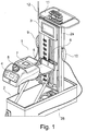
- Fig. 1 shows a mobile kit 1 with a housing 2 in which a device with a display unit 3, an operating unit 4, and a holding section 5 for a fluid receiving / dispensing vessel not shown here, such as a blood bag, are arranged.
- the housing 2 consists of a housing cover 2a and a housing body 2b.
- the housing cover 2a is open and is arranged essentially at right angles to the top edge or the bottom of the housing body 2b of the kit.
- a guide rail 6 is formed along the housing cover 2a, along which the holding section 5 is mounted in a height-adjustable manner.
- a scale indicates the height position of the holding section 5.
- a mixing balance 7 is arranged on the holding section 5, on which a fluid receiving / dispensing vessel, such as a blood bag, can be placed.
- a fluid receiving / dispensing vessel such as a blood bag
- the fill level of the fluid in the fluid receiving / dispensing vessel can be monitored.
- the inflow and outflow of fluid from the fluid intake / discharge vessel can be controlled by means of a controllable hose clamp 8.
- a user can control the operation of the device contained in the housing 2 of the kit 1. For example, the user can use various functions select the control unit 4.
- the kit 1 also has a reading unit 9, which here is a barcode reader. With this barcode reader 9, for example, identification data of a patient or of a fluid receiving / receiving vessel can be recorded.
- the kit 1 has a hose welding device 10 with which fluid lines and other hoses can be cut and sealed at the same time.
- an additional module is arranged on the end of the housing cover 2a facing away from the housing body 2b when the housing is open.
- the additional module is a tray 11 which is attached to the housing cover 2a.
- the operation of the device can be monitored via a warning display in the form of a light antenna 12. This light antenna indicates the operating mode of the device and any malfunction of the device by changing the color and / or the flashing frequency.
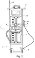
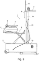
- FIGS. 2 to 4 show the same device as the Fig. 1 .
- Identical or similar components are denoted by the same reference numerals as in FIG Fig. 1 .
Landscapes
- Health & Medical Sciences (AREA)
- Heart & Thoracic Surgery (AREA)
- Vascular Medicine (AREA)
- Engineering & Computer Science (AREA)
- Anesthesiology (AREA)
- Biomedical Technology (AREA)
- Hematology (AREA)
- Life Sciences & Earth Sciences (AREA)
- Animal Behavior & Ethology (AREA)
- General Health & Medical Sciences (AREA)
- Public Health (AREA)
- Veterinary Medicine (AREA)
- External Artificial Organs (AREA)
- Infusion, Injection, And Reservoir Apparatuses (AREA)
Description
- Die vorliegende Erfindung betrifft eine Vorrichtung zur kontrollierten Entnahme von Blut von einem Patienten, sowie ein Kit mit einer derartigen Vorrichtung.
- Bei der kontrollierten Abgabe von Fluiden (z.B. von Infusionen) oder der Aufnahme von Fluiden (z.B. Blutentnahme, Blutspende) von einem Patienten wird herkömmlicherweise eine Vielzahl von Vorrichtungen verwendet. Beispielsweise wird das verwendete Gefäß zur Fluidaufnahme bzw. -abgabe meist auf einem höhenverstellbaren Tisch gelagert und die Fluidabgabe bzw. -aufnahme aus bzw. in das Gefäß wird über eine separate Bedieneinheit gesteuert. Die Verwendung separater Vorrichtungen ist jedoch zeitaufwendig und fehleranfällig, denn bevor mit der Abgabe bzw. Aufnahme von Fluiden begonnen werden kann, müssen zuerst die einzelnen Vorrichtungen wie z.B. der höhenverstellbare Tisch, die Bedieneinheit, eine Anzeigeeinheit für das Anzeigen des Betriebsverlaufs etc. miteinander verbunden werden und deren Einstellungen aufeinander abgestellt werden. Besonders im hektischen Klinikalltag kann es hierbei zu fehlerhaften Verbindungen zwischen einzelnen Vorrichtungen kommen oder die Höhe des höhenverstellbaren Tischs kann fehlerhaft eingestellt werden. Bei der Abgabe und Aufnahmen von Fluiden von einem Patienten ist jedoch die korrekte relative Höhenpositionierung zwischen dem Gefäß zur Fluidaufnahme bzw. -abgabe und dem Patienten für den Erfolg entscheidend.
- Zum besseren Verständnis der vorliegenden Erfindung sei auf die
US 5 112 019 A , in der eine Vorrichtung zur kontrollierten Abgabe und Aufnahme von Fluiden von einem Patienten - dort als "Motorized VB Pole Assembly" bezeichnet - beschrieben ist, auf dieEP 1 428 542 A2 , in der eine Stütze für einen Infusionsfluidbehälter - dort als "Infusion Fluid Container Support" bezeichnet - für den Einsatz in der Ophthalmologie beschrieben ist, und dieUS 2013/106609 A1 , die Anordnungen bzw. Vorrichtungen zur Stütze eines Dialysegeräts - dort "Dialysis Machine Support Assemblies" bezeichnet - offenbart, verwiesen. - Der vorliegenden Erfindung liegt die Aufgabe zugrunde, eine Vorrichtung zur kontrollierten Blutentnahme von einem Patienten zu schaffen, mit der Fehler bei der Entnahme aufgrund eines fehlerhaften Aufbaus der Vorrichtung vermieden werden und bei der zudem die relative Höhenpositionierung zwischen dem Patienten und dem zur Blutentnahme verwendeten Gefäß zuverlässig eingestellt werden kann.
- Diese Aufgabe wird gelöst durch die Vorrichtung mit den Merkmalen gemäß Anspruch 1 sowie durch ein Kit gemäß Anspruch 9 mit einer derartigen Vorrichtung.
- Eine erfindungsgemäße Vorrichtung zur kontrollierten Entnahme von Blut von einem Patienten weist mindestens eine Anzeigeeinheit, mindestens eine Bedieneinheit, sowie mindestens einen Halteabschnitt für ein Blutaufnahmegefäß auf. Hierbei ist die Anordnung des Halteabschnitts an der Vorrichtung über eine mittels der Bedieneinheit eingegebene Benutzereingabe einstellbar. Da die verschiedenen Komponenten Anzeigeeinheit, Bedieneinheit und Halteabschnitt bereits in einer Vorrichtung integriert sind, entfällt durch diese Vorrichtung die Notwendigkeit, mehrere Einzelkomponenten miteinander vor der Anwendung zu kombinieren und zu verbinden.
- Gemäß einem vorteilhaften und gegebenenfalls separat zu beanspruchenden Aspekt der Erfindung ist die relative Höhe des Halteabschnitts über einem Boden der Vorrichtung einstellbar. In anderen Worten ist erfindungsgemäß ein höhenverstellbarer Tisch oder ähnliches fest in der Vorrichtung zur kontrollierten Blutentnahme von einem Patienten integriert.
- Gemäß einem weiteren vorteilhaften und gegebenenfalls separat zu beanspruchenden Aspekt der Erfindung ist die Anordnung des Halteabschnitts in Antwort auf eine über die Bedieneinheit eingegebene Benutzereingabe, vorzugsweise in Antwort auf die Auswahl eines Betriebsmodus der Vorrichtung, falls die erfindungsgemäße Vorrichtung Teil einer allgemeineren Vorrichtung zur kontrollierten Abgabe und Aufnahme von Fluiden ist, automatisch einstellbar ist. Hierbei sind vorzugsweise in der allgemeineren Vorrichtung im Vorhinein mehrere Betriebsmodi bzw. Funktionen der Vorrichtung und diesen jeweils fest zugeordnete Höheneinstellungen des Halteabschnitts gespeichert, welche in Antwort auf eine Benutzereingabe abgerufen und zur Einstellung der Höhe des Halteabschnitts verwendet werden. Beispielsweise wird in der Bedieneinheit die Funktion "Blutentnahme" (vorliegende Erfindung) von einem Benutzer ausgewählt. Bei der Blutentnahme ist es vorteilhaft, wenn zwischen dem liegendem Blutspender und dem Blutaufnahmegefäß bzw. Blutbeutel ein Höhenunterschied von ca. 40 cm besteht. Ist beispielsweise bekannt, dass bei der Blutentnahme der Patient meist in einer Höhe von ca. 70 cm über dem Boden liegt, so kann in der Vorrichtung der Funktion "Blutentnahme" die Höheneinstellung "30 cm" zugeordnet und diese Zuordnung in der Vorrichtung gespeichert sein. Wählt der Benutzer die Funktion "Blutentnahme" aus, so liest die erfindungsgemäße Vorrichtung die gespeicherte Zuordnung zwischen dieser Funktion und der Höheneinstellung "30 cm" aus und stellt die Höhe des Halteabschnitts automatisch und ohne eine weitere Benutzereingabe auf 30 cm über dem Boden ein.
- Gemäß einem weiteren vorteilhaften und gegebenenfalls separat zu beanspruchenden Aspekt der Erfindung weist eine erfindungsgemäße Vorrichtung mindestens eine Leseeinheit zur Datenerfassung auf. Die Leseeinheit, z.B. ein Barcodeleser, kann hierbei ein beweglich mit der Vorrichtung verbundenes Handheld-Gerätsein oder baulich in der Vorrichtung integriert sein. Mit der mindestens einen Leseeinheit können beispielsweise Identifikationsdaten eines Gefäßes zur Blutentnahme von einem Patienten wie z.B. eines Blutbeutels eingelesen werden. Alternativ oder zusätzlich dazu können auch Identifikationsdaten beispielsweise von einem Armband eines Patienten eingelesen werden.
- Ist die Leseeinheit in der erfindungsgemäßen Vorrichtung baulich integriert, bietet dies den Vorteil, dass die Leseeinheit nicht wie bei einem Handheld-Gerät zum Auslesen von Daten händisch ergriffenwerden muss. Stattdessen kann beispielsweise das Gefäß zur Blutentnahme, z.B. ein Blutbeutel, zum Auslesen der Daten über die Leseeinheit bewegt werden. Zu diesem Zweck ist eine etwaige zwischen der Leseeinheit und der Außenseite der Vorrichtung angeordnete Außenwand der Vorrichtung zumindest abschnittsweise als ein Sichtfenster ausgestaltet, durch welches die Leseeinheit die Daten erfassen kann.
- Gemäß einem weiteren vorteilhaften und gegebenenfalls separat zu beanspruchenden Aspekt der Erfindung weist eine erfindungsgemäße Vorrichtung eine Warnanzeige, vorzugsweise in Form eines Lichtsignals auf, welche den Betriebsmodus und / oder eine Fehlfunktion der Vorrichtung anzeigt. Die Warnanzeige kann in Form eines ausgesandten Lichtstrahls (Lichtantenne), einer Warnleuchte oder auch als akustisches Signal ausgestaltet sein. Bei einer bevorzugten Ausführungsform der Erfindung ist die Warnanzeige als Lichtantenne ausgebildet. Die Farbe der Lichtantenne ist beispielsweise grün, wenn die Vorrichtung die Funktion "Blutentnahme" durchführt und blau, wenn die Blutentnahme beendet ist. Auch kann die Lichtantenne mit einer bestimmten Frequenz blinken, um beispielsweise eine fehlerhafte Funktion der Vorrichtung anzuzeigen. Verschiedene Frequenzen können hierbei verschiedene Fehler in verschiedenen Betriebsmodi der Vorrichtung anzeigen.
- Gemäß einem weiteren vorteilhaften und gegebenenfalls separat zu beanspruchenden Aspekt der Erfindung weist eine erfindungsgemäße Vorrichtung zudem ein Schlauchschweißgerät auf, mit dem an die Vorrichtung angeschlossene Schläuche gleichzeitig geschnitten und versiegelt werden können.
- Gemäß einem anderen vorteilhaften und gegebenenfalls separat zu beanspruchenden Aspekt der Erfindung weist eine erfindungsgemäße Vorrichtung zudem eine Datenschnittstelle auf, mit der von der mindestens einen Leseeinheit eingelesene Daten beispielsweise an eine Datenbank transferiert werden können oder mit in der Datenbank abgelegten Datensätzen abgeglichen werden können.
- Um die Anwendung der Vorrichtung weiter zu vereinfachen wird ein mobiles Kit zur kontrollierten Blutentnahme von einem Patienten mit einer erfindungsgemäßen Vorrichtung bereitgestellt.
- Ein erfindungsgemäßes Kit umfasst vorzugsweise einen Koffer, welcher eine erfindungsgemäße Vorrichtung zur kontrollierten Entnahme von Blut enthält. Hierbei können Funktionen der erfindungsgemäßen Vorrichtung in den Wänden des Gehäuses bzw. des Koffers des Kits integriert sein: Beispielsweise kann der aufgeklappte Deckel des Gehäuses als Führungsschiene dienen, an welcher der Halteabschnitt in seiner Höhenpositionierung verschiebbar ist. Hierbei ist der aufgeklappte Deckel des Gehäuses im Wesentlichen rechtwinklig zu dem Körper und Boden des Gehäuses angeordnet.
- Gemäß einem vorteilhaften und gegebenenfalls separat zu beanspruchenden Aspekt der Erfindung ist das mobile Kit von einem Menschen, beispielsweise von einer Krankenschwester, tragbar.
- Durch das erfindungsgemäße Kit wird die Durchführung einer kontrollierten Entnahme von Blut einem Patienten wesentlich vereinfacht und benutzerfreundlicher, denn die verschiedenen Komponenten der Vorrichtung zur kontrollierten Entnahme von Blut einem Patienten sind in dem Kit bereits korrekt miteinander verbunden und müssen daher nicht vor der Anwendung miteinander verbunden werden. Zudem erlaubt das Kit den einfachen Transport der erfindungsgemäßen Vorrichtung.
- Gemäß einem vorteilhaften und gegebenenfalls separat zu beanspruchenden Aspekt der Erfindung ist das Gehäuse des Kits, beispielsweise des Koffers, derart ausgestaltet, dass an dem Gehäuse mindestens ein zusätzliches Modul anbringbar ist. Dieses zusätzliche Modul kann beispielsweise eine Ablagefläche, ein Tablett oder eine Aufnahme sein.
- Um die Mobilität des erfindungsgemäßen Kits weiter zu verbessern, ist das Kit gemäß einem weiteren Aspekt der Erfindung mit einer Batterie ausgestattet.
- Weitere Merkmale und Vorteile der vorliegenden Erfindung ergeben sich aus der folgenden Beschreibung eines Ausführungsbeispiels unter Bezugnahme auf die zugehörigen Figuren. Hierbei zeigt:
-
Fig. 1 eine Perspektivansicht eines mobilen Kits zur kontrollierten Abgabe und Aufnahme von Fluiden von einem Patienten mit einer erfindungsgemäßen Vorrichtung zur kontrollierten Entnahme von Blut von dem Patienten, -
Fig. 2 eine Frontansicht des Kits ausFig. 1 , -
Fig. 3 eine Seitenansicht des Kits ausFig. 1 , und -
Fig. 4 eine Draufsicht des Kits ausFig. 4 . -
Fig. 1 zeigt ein mobiles Kit 1 mit einem Gehäuse 2, in welchem eine Vorrichtung mit einer Anzeigeeinheit 3, einer Bedieneinheit 4, und einem Halteabschnitt 5 für ein hier nicht gezeigtes Fluid-Aufnahme/-Abgabegefäß, wie beispielsweise einen Blutbeutel, angeordnet sind. Von der nachfolgenden Vorrichtung betrifft die vorliegende Erfindung jedoch nur den Teil der Blutennahme. Das Gehäuse 2 besteht aus einem Gehäusedeckel 2a und einem Gehäusekörper 2b. In der inFig. 1 gezeigten Ansicht ist der Gehäusedeckel 2a geöffnet und im Wesentlichen rechtwinklig zu der Oberkante bzw. dem Boden des Gehäusekörpers 2b des Kits angeordnet. Entlang des Gehäusedeckels 2a ist eine Führungsschiene 6 ausgebildet, entlang der der Halteabschnitt 5 höhenverstellbar gelagert ist. Hierbei zeigt eine Skale die Höhenposition des Halteabschnitts 5 an. Auf dem Halteabschnitt 5 ist in dieser Ausführungsform eine Mischwaage 7 angeordnet, auf welcher ein Fluidaufnahme/-abgabegefäß, wie beispielsweise einen Blutbeutel, aufgelegt werden kann. Durch die Messung des Gewichts des Fluid-Aufnahme/- Abgabegefäßes kann der Füllstand des Fluids in dem Fluidaufnahme/-abgabegefäß überwacht werden. Mittels einer steuerbaren Schlauchklemme 8 kann der Zu- bzw. Abfluss von Fluid von dem Fluidaufnahme/-abgabegefäß gesteuert werden. Mit der Bedieneinheit 4 kann ein Benutzer den Betrieb der in dem Gehäuse 2 des Kits 1 enthaltenen Vorrichtung steuern. Beispielsweise kann der Benutzer verschiedenen Funktionen über die Bedieneinheit 4 auswählen. Auf der Anzeigeeinheit 3 werden verschiedenen Information bezüglich des Betriebs der Vorrichtung angezeigt, wie beispielsweise die gewählte Funktion, die Identifikationsdaten eines Patienten oder eines Fluid-Aufnahme/- Abnahmegefäßes oder die Zeitdauer, für die die Vorrichtung bereits diese Funktion durchführt. Die Anzeigeeinheit 3 ist für einen Benutzer sehr einfach einsehbar an dem bei geöffnetem Gehäuse dem Gehäusekörper 2b abgewandten Ende des Gehäusedeckels 2a angeordnet. Weiterhin weist das Kit 1 eine Leseeinheit 9 auf, welche hier ein Barcodeleser ist. Mit diesem Barcodeleser 9 lassen sich beispielsweise Identifikationsdaten eines Patienten oder eines Fluid-Aufnahme/-Abnahmegefäßes erfassen. Zusätzlich weist das Kit 1 ein Schlauchschweißgerät 10 auf, mit welchem sich Fluidleitungen und sonstige Schläuche gleichzeitig schneiden und versiegeln lassen. Weiterhin ist an dem bei geöffnetem Gehäuse dem Gehäusekörper 2b abgewandten Ende des Gehäusedeckels 2a ein zusätzliches Modul angeordnet. In dieser Ausführungsform ist das zusätzliche Modul ein Tablett 11, welches auf den Gehäusedeckel 2a aufgesteckt ist. Der Betrieb der Vorrichtung kann über eine Warnanzeige in Form einer Lichtantenne 12 überwacht werden. Diese Lichtantenne zeigt durch Änderungen der Farbe und / oder der Blinkfrequenz den Betriebsmodus der Vorrichtung sowie eine etwaige Fehlfunktion der Vorrichtung an. - Die
Figuren 2 bis 4 zeigen dieselbe Vorrichtung wie dieFig. 1 . Gleiche oder ähnliche Bauteile sind hierbei mit den gleichen Bezugszeichen bezeichnet wie inFig. 1 .
Claims (14)
- Vorrichtung zur kontrollierten Blutentnahme von einem Patienten, mit:- mindestens einer Anzeigeeinheit (3),- mindestens einer Bedieneinheit (4), sowie- mindestens einem Halteabschnitt (5) für ein Blutentnahmegefäß, wobei die Anordnung des Halteabschnitts (5) an der Vorrichtung über eine mittels der Bedieneinheit (4) eingegebene Benutzereingabe einstellbar ist.
- Vorrichtung nach Anspruch 1, dadurch gekennzeichnet, dass die relative Höhe des Halteabschnitts (5) über einem Boden der Vorrichtung einstellbar ist.
- Vorrichtung nach einem der vorhergehenden Ansprüche, dadurch gekennzeichnet, dass die Anordnung des Halteabschnitts (5) in Antwort auf eine über die Bedieneinheit (4) eingegebene Benutzereingabe, vorzugsweise in Antwort auf die Auswahl eines Betriebsmodus der Vorrichtung, automatisch einstellbar ist.
- Vorrichtung nach einem der vorhergehenden Ansprüche, gekennzeichnet durch mindestens eine Leseeinheit (9) zur Datenerfassung.
- Vorrichtung nach Anspruch 4, dadurch gekennzeichnet, dass die Leseeinheit (9) ein beweglich mit der Vorrichtung verbundenes Handheld-Gerät ist oder baulich in der Vorrichtung integriert ist.
- Vorrichtung nach einem der vorhergehenden Ansprüche gekennzeichnet durch eine Warnanzeige (12), vorzugsweise in Form eines Lichtsignals, welche den Betriebsmodus und / oder eine Fehlfunktion der Vorrichtung anzeigt.
- Vorrichtung nach einem der vorhergehenden Ansprüche gekennzeichnet durch weiterhin ein Schlauchschweißgerät (10), mit dem an die Vorrichtung angeschlossene Schläuche gleichzeitig geschnitten und versiegelt werden können.
- Vorrichtung nach einem der vorhergehenden Ansprüche, gekennzeichnet durch weiterhin eine Datenschnittstelle, vorzugsweise zum Datenaustausch mit einer Datenbank.
- Mobiles Kit (1) zur kontrollierten Blutentnahme von einem Patienten mit einer Vorrichtung nach einem der Ansprüche 1 bis 8.
- Mobiles Kit (1) nach Anspruch 9, dadurch gekennzeichnet, dass das Kit (1) tragbar ist.
- Mobiles Kit (1) nach Anspruch 9 oder 10, dadurch gekennzeichnet, dass das Kit (1) ein Gehäuse (2), vorzugsweise in Form eines Koffers, aufweist.
- Mobiles Kit (1) nach Anspruch 11, dadurch gekennzeichnet, dass das Gehäuse (2) derart ausgestaltet ist, dass an dem Gehäuse (2) mindestens ein zusätzliches Modul (11) anbringbar ist.
- Mobiles Kit (1) nach Anspruch 12, dadurch gekennzeichnet, dass das mindestens eine zusätzliche Modul (11) eine Ablagefläche oder eine Aufnahme ist.
- Mobiles Kit (1) nach einem der Ansprüche 9 bis 13, mit weiterhin einer Batterie.
Applications Claiming Priority (1)
| Application Number | Priority Date | Filing Date | Title |
|---|---|---|---|
| DE202015103317.6U DE202015103317U1 (de) | 2015-06-24 | 2015-06-24 | Vorrichtung zur kontrollierten Abgabe und Aufnahme von Fluiden von einem Patienten, sowie Kit mit einer derartigen Vorrichtung |
Publications (3)
| Publication Number | Publication Date |
|---|---|
| EP3108908A1 EP3108908A1 (de) | 2016-12-28 |
| EP3108908B1 true EP3108908B1 (de) | 2021-11-03 |
| EP3108908B8 EP3108908B8 (de) | 2021-12-08 |
Family
ID=54193611
Family Applications (1)
| Application Number | Title | Priority Date | Filing Date |
|---|---|---|---|
| EP16172002.4A Active EP3108908B8 (de) | 2015-06-24 | 2016-05-30 | Vorrichtung zur kontrollierten blutenthame von einem patienten/spender sowie kit mit einer derartigen vorrichtung |
Country Status (2)
| Country | Link |
|---|---|
| EP (1) | EP3108908B8 (de) |
| DE (2) | DE202015103317U1 (de) |
Cited By (1)
| Publication number | Priority date | Publication date | Assignee | Title |
|---|---|---|---|---|
| EP4368221A1 (de) * | 2022-11-11 | 2024-05-15 | Fenwal, Inc. | System und verfahren zur änderung der blutdurchflussrate während der spenden |
Families Citing this family (4)
| Publication number | Priority date | Publication date | Assignee | Title |
|---|---|---|---|---|
| CN105561411A (zh) * | 2016-01-29 | 2016-05-11 | 武汉佰美斯医疗科技有限公司 | 一种多工位多媒体智能采血成套设备 |
| CN108815688B (zh) * | 2018-04-28 | 2020-09-22 | 广州保瑞医疗技术有限公司 | 膀胱热灌注装置及其防尘升降机构 |
| CN109569382B (zh) * | 2018-10-29 | 2021-08-17 | 深圳市迈思特生物医学工程有限公司 | 一种摇匀机构 |
| CA3196690A1 (en) * | 2020-10-26 | 2022-05-05 | Daniel M. Abal | Real time detection and monitoring of fluid volume and flow rate |
Family Cites Families (4)
| Publication number | Priority date | Publication date | Assignee | Title |
|---|---|---|---|---|
| US5112019A (en) * | 1991-02-04 | 1992-05-12 | Storz Instrument Company | Motorized IV pole assembly |
| ITFI20020246A1 (it) | 2002-12-13 | 2004-06-14 | Molteni & C | Contenitore sterile. |
| US6969032B2 (en) * | 2002-12-13 | 2005-11-29 | Alcon, Inc. | Infusion fluid container support |
| US9186449B2 (en) * | 2011-11-01 | 2015-11-17 | Fresenius Medical Care Holdings, Inc. | Dialysis machine support assemblies and related systems and methods |
-
2015
- 2015-06-24 DE DE202015103317.6U patent/DE202015103317U1/de not_active Expired - Lifetime
-
2016
- 2016-05-30 EP EP16172002.4A patent/EP3108908B8/de active Active
- 2016-05-30 DE DE202016009071.3U patent/DE202016009071U1/de active Active
Non-Patent Citations (1)
| Title |
|---|
| None * |
Cited By (1)
| Publication number | Priority date | Publication date | Assignee | Title |
|---|---|---|---|---|
| EP4368221A1 (de) * | 2022-11-11 | 2024-05-15 | Fenwal, Inc. | System und verfahren zur änderung der blutdurchflussrate während der spenden |
Also Published As
| Publication number | Publication date |
|---|---|
| DE202016009071U1 (de) | 2021-11-22 |
| EP3108908B8 (de) | 2021-12-08 |
| DE202015103317U1 (de) | 2015-09-04 |
| EP3108908A1 (de) | 2016-12-28 |
Similar Documents
| Publication | Publication Date | Title |
|---|---|---|
| EP3108908B1 (de) | Vorrichtung zur kontrollierten blutenthame von einem patienten/spender sowie kit mit einer derartigen vorrichtung | |
| EP3188767B1 (de) | Aufhängevorrichtung eines drainagebehälters | |
| CN110996795B (zh) | 生物流体收集装置 | |
| EP2168485A1 (de) | Brustfixierung für ein Untersuchungsgerät zur Untersuchung der weiblichen Brust | |
| DE69433688T2 (de) | Vorrichtung zur abnahme und einleitung von flüssigkeitsproben | |
| AT397610B (de) | Vorrichtung zur entnahme von körperflüssigkeiten | |
| US6869405B2 (en) | Blunt cannula and filter assembly and method of use with point-of-care testing cartridge | |
| DE2101423A1 (de) | ||
| EP2477742A2 (de) | Probeneingabevorrichtung zur eingabe von flüssigen proben (clot catcher) | |
| EP3160527A1 (de) | Medizinische saugpumpe und fluidsammelbehälter | |
| EP1665989A3 (de) | Fluidsteuerung für eine Biopsievorrichtung | |
| DE69833993T2 (de) | Sammelgefäss | |
| DE4409842A1 (de) | Vorrichtung und Verfahren zur medizinischen Körperfluid-Probenentnahme | |
| EP1876949A2 (de) | Blutdruckmessgerät | |
| DE102011102872A1 (de) | Blutbehandlungsvorrichtung und Verfahren zur Einstellung von Betriebsparametern einer Blutbehandlungsvorrichtung | |
| EP3278106B1 (de) | Verfahren und vorrichtung zur separation und analyse von blutbestandteilen | |
| DE3788265T2 (de) | Drainagevorrichtung. | |
| DE102007042153A1 (de) | Vorrichtung zur mobilen Versorgung eines Patienten | |
| EP1812099B1 (de) | Venenverweilkatheter | |
| EP3624870B1 (de) | Peritonealdialysesystem | |
| DE112018001367T5 (de) | Vorrichtung zur messung biologischer informationen sowie verfahren und programm | |
| WO2020053212A1 (de) | System zur analyse von aus dem körper stammenden flüssigkeiten oder mit ihnen in kontakt stehenden flüssigkeiten | |
| LU101301B1 (de) | Blutuntersuchungsgerät | |
| DE102010010336A1 (de) | Steuer-/Versorgungseinheit zum Betreiben eines medizinischen Handgeräts | |
| DE102009022060A1 (de) | Vorrichtung für eine Ultraschallgestützte Computertomographie mit erweitertem Messbereich |
Legal Events
| Date | Code | Title | Description |
|---|---|---|---|
| REG | Reference to a national code |
Ref country code: DE Ref legal event code: R138 Ref document number: 202016009071 Country of ref document: DE Free format text: GERMAN DOCUMENT NUMBER IS 502016014069 |
|
| PUAI | Public reference made under article 153(3) epc to a published international application that has entered the european phase |
Free format text: ORIGINAL CODE: 0009012 |
|
| STAA | Information on the status of an ep patent application or granted ep patent |
Free format text: STATUS: THE APPLICATION HAS BEEN PUBLISHED |
|
| AK | Designated contracting states |
Kind code of ref document: A1 Designated state(s): AL AT BE BG CH CY CZ DE DK EE ES FI FR GB GR HR HU IE IS IT LI LT LU LV MC MK MT NL NO PL PT RO RS SE SI SK SM TR |
|
| AX | Request for extension of the european patent |
Extension state: BA ME |
|
| STAA | Information on the status of an ep patent application or granted ep patent |
Free format text: STATUS: REQUEST FOR EXAMINATION WAS MADE |
|
| 17P | Request for examination filed |
Effective date: 20170406 |
|
| RBV | Designated contracting states (corrected) |
Designated state(s): AL AT BE BG CH CY CZ DE DK EE ES FI FR GB GR HR HU IE IS IT LI LT LU LV MC MK MT NL NO PL PT RO RS SE SI SK SM TR |
|
| STAA | Information on the status of an ep patent application or granted ep patent |
Free format text: STATUS: EXAMINATION IS IN PROGRESS |
|
| 17Q | First examination report despatched |
Effective date: 20190315 |
|
| GRAP | Despatch of communication of intention to grant a patent |
Free format text: ORIGINAL CODE: EPIDOSNIGR1 |
|
| STAA | Information on the status of an ep patent application or granted ep patent |
Free format text: STATUS: GRANT OF PATENT IS INTENDED |
|
| INTG | Intention to grant announced |
Effective date: 20210520 |
|
| GRAS | Grant fee paid |
Free format text: ORIGINAL CODE: EPIDOSNIGR3 |
|
| GRAA | (expected) grant |
Free format text: ORIGINAL CODE: 0009210 |
|
| STAA | Information on the status of an ep patent application or granted ep patent |
Free format text: STATUS: THE PATENT HAS BEEN GRANTED |
|
| AK | Designated contracting states |
Kind code of ref document: B1 Designated state(s): AL AT BE BG CH CY CZ DE DK EE ES FI FR GB GR HR HU IE IS IT LI LT LU LV MC MK MT NL NO PL PT RO RS SE SI SK SM TR |
|
| REG | Reference to a national code |
Ref country code: GB Ref legal event code: FG4D Free format text: NOT ENGLISH |
|
| REG | Reference to a national code |
Ref country code: AT Ref legal event code: REF Ref document number: 1443393 Country of ref document: AT Kind code of ref document: T Effective date: 20211115 Ref country code: CH Ref legal event code: PK Free format text: BERICHTIGUNG B8 Ref country code: CH Ref legal event code: EP |
|
| REG | Reference to a national code |
Ref country code: DE Ref legal event code: R096 Ref document number: 502016014069 Country of ref document: DE |
|
| REG | Reference to a national code |
Ref country code: IE Ref legal event code: FG4D Free format text: LANGUAGE OF EP DOCUMENT: GERMAN |
|
| REG | Reference to a national code |
Ref country code: LT Ref legal event code: MG9D |
|
| REG | Reference to a national code |
Ref country code: NL Ref legal event code: MP Effective date: 20211103 |
|
| PG25 | Lapsed in a contracting state [announced via postgrant information from national office to epo] |
Ref country code: RS Free format text: LAPSE BECAUSE OF FAILURE TO SUBMIT A TRANSLATION OF THE DESCRIPTION OR TO PAY THE FEE WITHIN THE PRESCRIBED TIME-LIMIT Effective date: 20211103 Ref country code: LT Free format text: LAPSE BECAUSE OF FAILURE TO SUBMIT A TRANSLATION OF THE DESCRIPTION OR TO PAY THE FEE WITHIN THE PRESCRIBED TIME-LIMIT Effective date: 20211103 Ref country code: FI Free format text: LAPSE BECAUSE OF FAILURE TO SUBMIT A TRANSLATION OF THE DESCRIPTION OR TO PAY THE FEE WITHIN THE PRESCRIBED TIME-LIMIT Effective date: 20211103 Ref country code: BG Free format text: LAPSE BECAUSE OF FAILURE TO SUBMIT A TRANSLATION OF THE DESCRIPTION OR TO PAY THE FEE WITHIN THE PRESCRIBED TIME-LIMIT Effective date: 20220203 |
|
| PG25 | Lapsed in a contracting state [announced via postgrant information from national office to epo] |
Ref country code: IS Free format text: LAPSE BECAUSE OF FAILURE TO SUBMIT A TRANSLATION OF THE DESCRIPTION OR TO PAY THE FEE WITHIN THE PRESCRIBED TIME-LIMIT Effective date: 20220303 Ref country code: SK Free format text: LAPSE BECAUSE OF FAILURE TO SUBMIT A TRANSLATION OF THE DESCRIPTION OR TO PAY THE FEE WITHIN THE PRESCRIBED TIME-LIMIT Effective date: 20211103 Ref country code: SE Free format text: LAPSE BECAUSE OF FAILURE TO SUBMIT A TRANSLATION OF THE DESCRIPTION OR TO PAY THE FEE WITHIN THE PRESCRIBED TIME-LIMIT Effective date: 20211103 Ref country code: PT Free format text: LAPSE BECAUSE OF FAILURE TO SUBMIT A TRANSLATION OF THE DESCRIPTION OR TO PAY THE FEE WITHIN THE PRESCRIBED TIME-LIMIT Effective date: 20220303 Ref country code: PL Free format text: LAPSE BECAUSE OF FAILURE TO SUBMIT A TRANSLATION OF THE DESCRIPTION OR TO PAY THE FEE WITHIN THE PRESCRIBED TIME-LIMIT Effective date: 20211103 Ref country code: NO Free format text: LAPSE BECAUSE OF FAILURE TO SUBMIT A TRANSLATION OF THE DESCRIPTION OR TO PAY THE FEE WITHIN THE PRESCRIBED TIME-LIMIT Effective date: 20220203 Ref country code: NL Free format text: LAPSE BECAUSE OF FAILURE TO SUBMIT A TRANSLATION OF THE DESCRIPTION OR TO PAY THE FEE WITHIN THE PRESCRIBED TIME-LIMIT Effective date: 20211103 Ref country code: LV Free format text: LAPSE BECAUSE OF FAILURE TO SUBMIT A TRANSLATION OF THE DESCRIPTION OR TO PAY THE FEE WITHIN THE PRESCRIBED TIME-LIMIT Effective date: 20211103 Ref country code: HR Free format text: LAPSE BECAUSE OF FAILURE TO SUBMIT A TRANSLATION OF THE DESCRIPTION OR TO PAY THE FEE WITHIN THE PRESCRIBED TIME-LIMIT Effective date: 20211103 Ref country code: GR Free format text: LAPSE BECAUSE OF FAILURE TO SUBMIT A TRANSLATION OF THE DESCRIPTION OR TO PAY THE FEE WITHIN THE PRESCRIBED TIME-LIMIT Effective date: 20220204 Ref country code: ES Free format text: LAPSE BECAUSE OF FAILURE TO SUBMIT A TRANSLATION OF THE DESCRIPTION OR TO PAY THE FEE WITHIN THE PRESCRIBED TIME-LIMIT Effective date: 20211103 |
|
| PG25 | Lapsed in a contracting state [announced via postgrant information from national office to epo] |
Ref country code: SM Free format text: LAPSE BECAUSE OF FAILURE TO SUBMIT A TRANSLATION OF THE DESCRIPTION OR TO PAY THE FEE WITHIN THE PRESCRIBED TIME-LIMIT Effective date: 20211103 Ref country code: RO Free format text: LAPSE BECAUSE OF FAILURE TO SUBMIT A TRANSLATION OF THE DESCRIPTION OR TO PAY THE FEE WITHIN THE PRESCRIBED TIME-LIMIT Effective date: 20211103 Ref country code: EE Free format text: LAPSE BECAUSE OF FAILURE TO SUBMIT A TRANSLATION OF THE DESCRIPTION OR TO PAY THE FEE WITHIN THE PRESCRIBED TIME-LIMIT Effective date: 20211103 Ref country code: DK Free format text: LAPSE BECAUSE OF FAILURE TO SUBMIT A TRANSLATION OF THE DESCRIPTION OR TO PAY THE FEE WITHIN THE PRESCRIBED TIME-LIMIT Effective date: 20211103 Ref country code: CZ Free format text: LAPSE BECAUSE OF FAILURE TO SUBMIT A TRANSLATION OF THE DESCRIPTION OR TO PAY THE FEE WITHIN THE PRESCRIBED TIME-LIMIT Effective date: 20211103 |
|
| REG | Reference to a national code |
Ref country code: DE Ref legal event code: R097 Ref document number: 502016014069 Country of ref document: DE |
|
| PLBE | No opposition filed within time limit |
Free format text: ORIGINAL CODE: 0009261 |
|
| STAA | Information on the status of an ep patent application or granted ep patent |
Free format text: STATUS: NO OPPOSITION FILED WITHIN TIME LIMIT |
|
| 26N | No opposition filed |
Effective date: 20220804 |
|
| PG25 | Lapsed in a contracting state [announced via postgrant information from national office to epo] |
Ref country code: AL Free format text: LAPSE BECAUSE OF FAILURE TO SUBMIT A TRANSLATION OF THE DESCRIPTION OR TO PAY THE FEE WITHIN THE PRESCRIBED TIME-LIMIT Effective date: 20211103 |
|
| PG25 | Lapsed in a contracting state [announced via postgrant information from national office to epo] |
Ref country code: SI Free format text: LAPSE BECAUSE OF FAILURE TO SUBMIT A TRANSLATION OF THE DESCRIPTION OR TO PAY THE FEE WITHIN THE PRESCRIBED TIME-LIMIT Effective date: 20211103 |
|
| REG | Reference to a national code |
Ref country code: CH Ref legal event code: PL |
|
| REG | Reference to a national code |
Ref country code: BE Ref legal event code: MM Effective date: 20220531 |
|
| GBPC | Gb: european patent ceased through non-payment of renewal fee |
Effective date: 20220530 |
|
| PG25 | Lapsed in a contracting state [announced via postgrant information from national office to epo] |
Ref country code: MC Free format text: LAPSE BECAUSE OF FAILURE TO SUBMIT A TRANSLATION OF THE DESCRIPTION OR TO PAY THE FEE WITHIN THE PRESCRIBED TIME-LIMIT Effective date: 20211103 Ref country code: LU Free format text: LAPSE BECAUSE OF NON-PAYMENT OF DUE FEES Effective date: 20220530 Ref country code: LI Free format text: LAPSE BECAUSE OF NON-PAYMENT OF DUE FEES Effective date: 20220531 Ref country code: CH Free format text: LAPSE BECAUSE OF NON-PAYMENT OF DUE FEES Effective date: 20220531 |
|
| PG25 | Lapsed in a contracting state [announced via postgrant information from national office to epo] |
Ref country code: IE Free format text: LAPSE BECAUSE OF NON-PAYMENT OF DUE FEES Effective date: 20220530 |
|
| PG25 | Lapsed in a contracting state [announced via postgrant information from national office to epo] |
Ref country code: GB Free format text: LAPSE BECAUSE OF NON-PAYMENT OF DUE FEES Effective date: 20220530 Ref country code: BE Free format text: LAPSE BECAUSE OF NON-PAYMENT OF DUE FEES Effective date: 20220531 |
|
| REG | Reference to a national code |
Ref country code: AT Ref legal event code: MM01 Ref document number: 1443393 Country of ref document: AT Kind code of ref document: T Effective date: 20220530 |
|
| PG25 | Lapsed in a contracting state [announced via postgrant information from national office to epo] |
Ref country code: AT Free format text: LAPSE BECAUSE OF NON-PAYMENT OF DUE FEES Effective date: 20220530 |
|
| PG25 | Lapsed in a contracting state [announced via postgrant information from national office to epo] |
Ref country code: HU Free format text: LAPSE BECAUSE OF FAILURE TO SUBMIT A TRANSLATION OF THE DESCRIPTION OR TO PAY THE FEE WITHIN THE PRESCRIBED TIME-LIMIT; INVALID AB INITIO Effective date: 20160530 |
|
| PG25 | Lapsed in a contracting state [announced via postgrant information from national office to epo] |
Ref country code: MK Free format text: LAPSE BECAUSE OF FAILURE TO SUBMIT A TRANSLATION OF THE DESCRIPTION OR TO PAY THE FEE WITHIN THE PRESCRIBED TIME-LIMIT Effective date: 20211103 Ref country code: CY Free format text: LAPSE BECAUSE OF FAILURE TO SUBMIT A TRANSLATION OF THE DESCRIPTION OR TO PAY THE FEE WITHIN THE PRESCRIBED TIME-LIMIT Effective date: 20211103 |
|
| PG25 | Lapsed in a contracting state [announced via postgrant information from national office to epo] |
Ref country code: MT Free format text: LAPSE BECAUSE OF FAILURE TO SUBMIT A TRANSLATION OF THE DESCRIPTION OR TO PAY THE FEE WITHIN THE PRESCRIBED TIME-LIMIT Effective date: 20211103 |
|
| PGFP | Annual fee paid to national office [announced via postgrant information from national office to epo] |
Ref country code: DE Payment date: 20250326 Year of fee payment: 10 |
|
| PGFP | Annual fee paid to national office [announced via postgrant information from national office to epo] |
Ref country code: IT Payment date: 20250530 Year of fee payment: 10 |
|
| PGFP | Annual fee paid to national office [announced via postgrant information from national office to epo] |
Ref country code: FR Payment date: 20250521 Year of fee payment: 10 |
|
| PG25 | Lapsed in a contracting state [announced via postgrant information from national office to epo] |
Ref country code: TR Free format text: LAPSE BECAUSE OF FAILURE TO SUBMIT A TRANSLATION OF THE DESCRIPTION OR TO PAY THE FEE WITHIN THE PRESCRIBED TIME-LIMIT Effective date: 20211103 |