EP3108910A1 - Genaue spritzenpumpe und herstellungsverfahren dafür - Google Patents
Genaue spritzenpumpe und herstellungsverfahren dafür Download PDFInfo
- Publication number
- EP3108910A1 EP3108910A1 EP15751470.4A EP15751470A EP3108910A1 EP 3108910 A1 EP3108910 A1 EP 3108910A1 EP 15751470 A EP15751470 A EP 15751470A EP 3108910 A1 EP3108910 A1 EP 3108910A1
- Authority
- EP
- European Patent Office
- Prior art keywords
- lead screw
- syringe pump
- permanent magnet
- syringe
- motor
- Prior art date
- Legal status (The legal status is an assumption and is not a legal conclusion. Google has not performed a legal analysis and makes no representation as to the accuracy of the status listed.)
- Withdrawn
Links
Images


Classifications
-
- A—HUMAN NECESSITIES
- A61—MEDICAL OR VETERINARY SCIENCE; HYGIENE
- A61M—DEVICES FOR INTRODUCING MEDIA INTO, OR ONTO, THE BODY; DEVICES FOR TRANSDUCING BODY MEDIA OR FOR TAKING MEDIA FROM THE BODY; DEVICES FOR PRODUCING OR ENDING SLEEP OR STUPOR
- A61M5/00—Devices for bringing media into the body in a subcutaneous, intra-vascular or intramuscular way; Accessories therefor, e.g. filling or cleaning devices, arm-rests
- A61M5/14—Infusion devices, e.g. infusing by gravity; Blood infusion; Accessories therefor
- A61M5/142—Pressure infusion, e.g. using pumps
- A61M5/14212—Pumping with an aspiration and an expulsion action
- A61M5/14216—Reciprocating piston type
-
- A—HUMAN NECESSITIES
- A61—MEDICAL OR VETERINARY SCIENCE; HYGIENE
- A61M—DEVICES FOR INTRODUCING MEDIA INTO, OR ONTO, THE BODY; DEVICES FOR TRANSDUCING BODY MEDIA OR FOR TAKING MEDIA FROM THE BODY; DEVICES FOR PRODUCING OR ENDING SLEEP OR STUPOR
- A61M5/00—Devices for bringing media into the body in a subcutaneous, intra-vascular or intramuscular way; Accessories therefor, e.g. filling or cleaning devices, arm-rests
- A61M5/14—Infusion devices, e.g. infusing by gravity; Blood infusion; Accessories therefor
- A61M5/142—Pressure infusion, e.g. using pumps
- A61M5/145—Pressure infusion, e.g. using pumps using pressurised reservoirs, e.g. pressurised by means of pistons
- A61M5/1452—Pressure infusion, e.g. using pumps using pressurised reservoirs, e.g. pressurised by means of pistons pressurised by means of pistons
-
- A—HUMAN NECESSITIES
- A61—MEDICAL OR VETERINARY SCIENCE; HYGIENE
- A61M—DEVICES FOR INTRODUCING MEDIA INTO, OR ONTO, THE BODY; DEVICES FOR TRANSDUCING BODY MEDIA OR FOR TAKING MEDIA FROM THE BODY; DEVICES FOR PRODUCING OR ENDING SLEEP OR STUPOR
- A61M5/00—Devices for bringing media into the body in a subcutaneous, intra-vascular or intramuscular way; Accessories therefor, e.g. filling or cleaning devices, arm-rests
- A61M5/14—Infusion devices, e.g. infusing by gravity; Blood infusion; Accessories therefor
- A61M5/142—Pressure infusion, e.g. using pumps
- A61M5/14212—Pumping with an aspiration and an expulsion action
- A61M5/14236—Screw, impeller or centrifugal type pumps
-
- A—HUMAN NECESSITIES
- A61—MEDICAL OR VETERINARY SCIENCE; HYGIENE
- A61M—DEVICES FOR INTRODUCING MEDIA INTO, OR ONTO, THE BODY; DEVICES FOR TRANSDUCING BODY MEDIA OR FOR TAKING MEDIA FROM THE BODY; DEVICES FOR PRODUCING OR ENDING SLEEP OR STUPOR
- A61M5/00—Devices for bringing media into the body in a subcutaneous, intra-vascular or intramuscular way; Accessories therefor, e.g. filling or cleaning devices, arm-rests
- A61M5/14—Infusion devices, e.g. infusing by gravity; Blood infusion; Accessories therefor
- A61M5/168—Means for controlling media flow to the body or for metering media to the body, e.g. drip meters, counters ; Monitoring media flow to the body
- A61M5/16831—Monitoring, detecting, signalling or eliminating infusion flow anomalies
- A61M5/1684—Monitoring, detecting, signalling or eliminating infusion flow anomalies by detecting the amount of infusate remaining, e.g. signalling end of infusion
-
- A—HUMAN NECESSITIES
- A61—MEDICAL OR VETERINARY SCIENCE; HYGIENE
- A61M—DEVICES FOR INTRODUCING MEDIA INTO, OR ONTO, THE BODY; DEVICES FOR TRANSDUCING BODY MEDIA OR FOR TAKING MEDIA FROM THE BODY; DEVICES FOR PRODUCING OR ENDING SLEEP OR STUPOR
- A61M5/00—Devices for bringing media into the body in a subcutaneous, intra-vascular or intramuscular way; Accessories therefor, e.g. filling or cleaning devices, arm-rests
- A61M5/14—Infusion devices, e.g. infusing by gravity; Blood infusion; Accessories therefor
- A61M5/168—Means for controlling media flow to the body or for metering media to the body, e.g. drip meters, counters ; Monitoring media flow to the body
- A61M5/16886—Means for controlling media flow to the body or for metering media to the body, e.g. drip meters, counters ; Monitoring media flow to the body for measuring fluid flow rate, i.e. flowmeters
-
- A—HUMAN NECESSITIES
- A61—MEDICAL OR VETERINARY SCIENCE; HYGIENE
- A61M—DEVICES FOR INTRODUCING MEDIA INTO, OR ONTO, THE BODY; DEVICES FOR TRANSDUCING BODY MEDIA OR FOR TAKING MEDIA FROM THE BODY; DEVICES FOR PRODUCING OR ENDING SLEEP OR STUPOR
- A61M5/00—Devices for bringing media into the body in a subcutaneous, intra-vascular or intramuscular way; Accessories therefor, e.g. filling or cleaning devices, arm-rests
- A61M5/14—Infusion devices, e.g. infusing by gravity; Blood infusion; Accessories therefor
- A61M5/168—Means for controlling media flow to the body or for metering media to the body, e.g. drip meters, counters ; Monitoring media flow to the body
- A61M5/172—Means for controlling media flow to the body or for metering media to the body, e.g. drip meters, counters ; Monitoring media flow to the body electrical or electronic
-
- A—HUMAN NECESSITIES
- A61—MEDICAL OR VETERINARY SCIENCE; HYGIENE
- A61M—DEVICES FOR INTRODUCING MEDIA INTO, OR ONTO, THE BODY; DEVICES FOR TRANSDUCING BODY MEDIA OR FOR TAKING MEDIA FROM THE BODY; DEVICES FOR PRODUCING OR ENDING SLEEP OR STUPOR
- A61M2205/00—General characteristics of the apparatus
- A61M2205/18—General characteristics of the apparatus with alarm
-
- A—HUMAN NECESSITIES
- A61—MEDICAL OR VETERINARY SCIENCE; HYGIENE
- A61M—DEVICES FOR INTRODUCING MEDIA INTO, OR ONTO, THE BODY; DEVICES FOR TRANSDUCING BODY MEDIA OR FOR TAKING MEDIA FROM THE BODY; DEVICES FOR PRODUCING OR ENDING SLEEP OR STUPOR
- A61M2205/00—General characteristics of the apparatus
- A61M2205/33—Controlling, regulating or measuring
- A61M2205/3317—Electromagnetic, inductive or dielectric measuring means
-
- A—HUMAN NECESSITIES
- A61—MEDICAL OR VETERINARY SCIENCE; HYGIENE
- A61M—DEVICES FOR INTRODUCING MEDIA INTO, OR ONTO, THE BODY; DEVICES FOR TRANSDUCING BODY MEDIA OR FOR TAKING MEDIA FROM THE BODY; DEVICES FOR PRODUCING OR ENDING SLEEP OR STUPOR
- A61M2205/00—General characteristics of the apparatus
- A61M2205/33—Controlling, regulating or measuring
- A61M2205/3365—Rotational speed
-
- A—HUMAN NECESSITIES
- A61—MEDICAL OR VETERINARY SCIENCE; HYGIENE
- A61M—DEVICES FOR INTRODUCING MEDIA INTO, OR ONTO, THE BODY; DEVICES FOR TRANSDUCING BODY MEDIA OR FOR TAKING MEDIA FROM THE BODY; DEVICES FOR PRODUCING OR ENDING SLEEP OR STUPOR
- A61M2205/00—General characteristics of the apparatus
- A61M2205/33—Controlling, regulating or measuring
- A61M2205/3379—Masses, volumes, levels of fluids in reservoirs, flow rates
- A61M2205/3389—Continuous level detection
-
- A—HUMAN NECESSITIES
- A61—MEDICAL OR VETERINARY SCIENCE; HYGIENE
- A61M—DEVICES FOR INTRODUCING MEDIA INTO, OR ONTO, THE BODY; DEVICES FOR TRANSDUCING BODY MEDIA OR FOR TAKING MEDIA FROM THE BODY; DEVICES FOR PRODUCING OR ENDING SLEEP OR STUPOR
- A61M2207/00—Methods of manufacture, assembly or production
Definitions
- the present invention relates to a medical device, and in particular, to a syringe pump for infusion.
- infusion pumps allow automatically infusing liquid drugs or nutrients to patients intravenously at a set speed within a relatively longer time, which reduces the workload of medical staff and improves the security of infusion.
- the infusion pumps are divided into different types, among which capacity pumps and syringe pumps are common.
- the capacity pumps can be driven by peristaltic pumps; and the syringe pumps can be driven by lead screw pumps.
- a motor drives a lead screw to rotate, changes rotational motion into linear motion, and pushes a plunger to inject liquid in a syringe into a patient's vein through a nut connected with the plunger.
- the precision of an infusion speed of the syringe pumps is higher than that of the capacity pumps, of which an error is about ⁇ 5%.
- During infusion it is also necessary to know the position of the plunger in the syringe.
- a common practice is to use a step motor, and it is also feasible to use a linear or rotating potentiometer or an optical decoder to control the infusion speed, but these methods still have problems of low precision, poor reliability and high manufacturing cost.
- the present invention adopts the following technical solution:
- the magnetoresistive sensor is a Hall, AMR, GMR or TMR sensor.
- central axes of the at least one permanent magnet and the lead screw pass through the center of the magnetoresistive sensor.
- the magnetoresistive sensor is in the vicinity of the at least one permanent magnet.
- the at least one permanent magnet is an integrated permanent magnet or a separated permanent magnet, and is disc-shaped, annular or square; the integrated permanent magnet or separated permanent magnet is located on the same end of the lead screw as the motor or the other end of the lead screw.
- each of the permanent magnets has a plurality of different magnetic poles, and the two permanent magnets are respectively located on two ends of the lead screw or placed on the same end of the lead screw in series.
- the permanent magnet is magnetized along the diameter or the diagonal line of the permanent magnet or along a direction vertical to a long axis of the lead screw, and an internal magnetization direction of the permanent magnet is perpendicular to the long axis of the lead screw.
- a surface area of the magnetoresistive sensor in an XY plane is less than a cover area of the permanent magnet in the XY plane.
- the MCU comprises a magnetoresistive sensor information management unit for converting a rotating speed of the lead screw to an infusion speed of the syringe.
- the magnetoresistive sensor information management unit comprises a motor rotation angle counting unit, a lead screw position unit and/or a plunger position unit, a solution volume unit and a flow rate unit.
- the MCU comprises a comparator for comparing the infusion speed of the syringe with a set infusion speed, and the MCU adjusts the rotating speed of the lead screw according to a comparison result.
- the syringe pump comprises a motor controller and an alarm, wherein the MCU controls the rotating direction and the rotating speed of the motor through the motor controller, and the alarm is connected with the motor controller.
- the syringe pump comprises at least one guide rod parallel to the lead screw, wherein one end of the syringe driving head is placed on the guide rod in a manner that permits it to slide, the lead screw passes through a hole with screw threads which is located on the other end of the syringe driving head, the guide rod is fixed onto a base, and the lead screw is rotatably fixed onto the base.
- the motor is a DC motor or a step motor.
- the syringe pump comprises a mechanical transmission device connecting the motor and the lead screw; the mechanical transmission device being at least one gear and a reduction gear or a pulley and a transmission belt.
- the invention discloses a method of manufacturing the syringe pump.
- the syringe pump comprises a motor, a lead screw and a syringe driving head connected to the lead screw, and the motor drives the lead screw to rotate clockwise or counterclockwise to drive the syringe driving head and push the plunger to move within the cylinder, wherein at least one permanent magnet is disposed on the lead screw, making the permanent magnet rotate with the lead screw; the magnetoresistive sensor is disposed in a position on the syringe pump where a magnetic signal generated by the at least one permanent magnet can be received; and an MCU for controlling the direction and velocity of the lead screw rotated by the motor according to magnetic signal feedback is installed on the syringe pump.
- the magnetoresistive sensor is a Hall, AMR, GMR or TMR sensor.
- a magnetoresistive sensor and a Micro Control Unit are employed to feed back and control an infusion speed and monitor the position of the plunger in the syringe, which replaces the manner of controlling the infusion speed with a step motor.
- MCU Micro Control Unit
- Precision of controlling the infusion speed by the step motor depends on the number of phases and the number of beats, the more the number of phases and the number of beats are, the higher the precision is. At a low speed, the step motor is prone to low frequency vibration.
- the starting frequency is too high or the load is too large, it is easy to lead to a step loss or rotation blockage, and when the step motor stops, it is easy to lead to overshoot due to overhigh rotating speed.
- another motor can be used to replace the step motor, and can also be used together with the step motor, which improves precision and reliability of the infusion speed of the syringe pump.
- an ordinary DC motor instead of an expensive step motor may be used, which thus reduces the cost of the syringe pump.
- the precision syringe pump of the present invention is characterized by high sensitivity, high reliability, low power consumption and low cost, and is convenient to use.
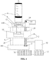
- FIG. 1 is a top view of a syringe pump 2.
- a syringe pump 2 that can employ a syringe 4 comprises a motor 52, a lead screw 22 and a syringe driving head 18.
- the syringe 4 comprises a cylinder 6 and a plunger 8.
- the motor 52 drives the lead screw 22 to rotate clockwise or counterclockwise to drive the syringe driving head 18 and push the plunger 8 to move within the cylinder 6;
- the syringe pump 2 further comprises a magnetoresistive sensor 28, at least one permanent magnet 30 and an MCU 50;
- the permanent magnet 30 is located on the lead screw 22, and rotates therewith;
- the magnetoresistive sensor 28 can sense a magnetic field generated by the permanent magnet 30;
- an input end of the MCU 50 is connected with the magnetoresistive sensor 28, and an output end is connected with the motor 52;
- the MCU50 receives signals from the magnetoresistive sensor 28 and, according to the signal feedback, controls the direction and velocity of the lead screw 22 rotated by the motor 52.
- One end of the lead screw 22 connected with the motor 52 is rotatably fixed onto a front base 16A through a bearing 21, and the other end passes through a hole 20 without screw threads on a rear base 16B to be rotatably fixed onto the rear base 16B.
- the lead screw 22 passes through a hole 7 with an internal thread on the syringe driving head 18 which matches an external thread of the lead screw 22.
- the motor 52 drives the lead screw 22 to rotate clockwise or counterclockwise in the hole 7 in the syringe driving head 18 through a mechanical transmission device that can change a rotating speed, for example, one or more reduction gears 13 and gears 31, so that the lead screw 22 drives the syringe driving head 18 to linearly move repeatedly.
- a mechanical transmission device that can change a rotating speed, for example, one or more reduction gears 13 and gears 31, so that the lead screw 22 drives the syringe driving head 18 to linearly move repeatedly.
- a guide rod 26 playing a role of stabilization and guide passes through a hole 5 without screw threads on the other end of the syringe driving head 18 and is disposed in parallel to the lead screw 22.
- the syringe driving head 18 may also move along a slide rail which is parallel to the lead screw 22.
- the motor 52 may be a DC motor, an AC motor, a step motor, a servo motor or the like.
- the syringe driving head 18 is provided with a pair of plunger clamps 14 that can fix and hold the plungers 8 of the syringes 4 with different diameters; therefore, when the lead screw 22 rotates in the hole 7 of the syringe driving head 18, the syringe driving head 18 makes linear motion along the direction of the guide rod 26, so as to push or pull the plunger 8 to move in the cylinder 6.
- a pair of cylinder clamps 12 is mounted on the rear base 16B, which can fix the cylinders 6 of the syringes 4 with different diameters.
- FIG. 2 is a schematic sectional view showing a position relationship between a magnetoresistive sensor and a permanent magnet and a schematic view showing a magnetization direction of the permanent magnet.
- the permanent magnet 30 rotates with the lead screw 22 along a rotating direction 17, while the magnetoresistive sensor 28 is stationary.
- the magnetoresistive sensor 28 is a biaxial rotary magnetic sensor or two orthogonal uniaxial rotary sensors, and may also be a uniaxial linear sensor or a biaxial linear sensor.
- the existing magnetoresistive sensing elements include Hall elements, Anisotropic Magneto Resistance (AMR) elements or Giant Magneto Resistance (GMR) elements and Tunnel Magneto Resistance (TMR) elements.
- AMR Anisotropic Magneto Resistance
- GMR Giant Magneto Resistance
- TMR Tunnel Magneto Resistance
- the TMR technology is the most advanced and is also a preferred technology of the present invention, but other magnetoresistive sensing elements may also be used for the magnetoresistive sensor 28.
- the permanent magnet 30 is an integrated or separated permanent magnet, and is disc-shaped, annular or square. Two permanent magnets 30 may be provided, each of which has multiple different magnetic poles.
- FIGs. 2B, 2C and 2D show that the permanent magnet 30 is disc-shaped, square, and is a separated permanent magnet and show some respective possible magnetization directions, but do not show all possible shapes and magnetization directions.
- the aforementioned permanent magnet 30 has a thickness that satisfies a suitable application condition.
- a surface area of the magnetoresistive sensor 28 in an XY plane is less than a cover area of the permanent magnet 30 in the XY plane.
- the lead screw 22 has a long axis 15 in a Z-axis direction, and the long axis 15 is perpendicular to the XY plane, passes through the center of the permanent magnet 30, and is coaxial with the permanent magnet 30. Central axes of the permanent magnet 30 and the lead screw 22 pass through the center of the magnetoresistive sensor 28.
- the permanent magnet 30 is magnetized along a diameter or a diagonal direction, and a magnetization direction thereof is perpendicular to the Z-axis direction or the long axis direction of the lead screw 22.
- the disc-shaped and annular permanent magnets are magnetized along the diameter direction, and the square permanent magnets are magnetized along the diagonal direction.
- the permanent magnets may also be magnetized along a direction perpendicular to the long axis of the lead screw.
- the permanent magnet 30 may be located on one end of the lead screw 22 away from the motor 52, and may also be on the same end therewith. If two permanent magnets 30 are provided, the two permanent magnets are respectively located on two ends of the lead screw 22 or placed on the same end of the lead screw 22 in series.
- the magnetoresistive sensor 28 is in the vicinity of the permanent magnet 30, and may also be away from the permanent magnet 30. If the two permanent magnets 30 are placed on the same end of the lead screw 22 in series, the magnetoresistive sensor 28 may be in the vicinity of the lead screw 22 and may also be away from the lead screw 22.
- the permanent magnet 30 has a rotational phase angle ⁇ during rotation.
- the magnetoresistive sensor 28 forms sine and cosine to output a rotational magnetic field phase angle f formed between a detection magnetic field component of the permanent magnet 30 and a sensitive axis of the magnetoresistive sensor 28. Only when a linear relationship formed between a and f satisfies one-to-one correspondence within a range of 0 to 360°, can a position relationship between the rotational magnetic field phase angle f detected by the magnetoresistive sensor 28 and the rotational phase angle a of the permanent magnet 30 correspond to each other.
- the magnetoresistive sensor 28 should be disposed in a detection region of the permanent magnet 30 that can satisfy the foregoing requirements.
- FIG. 4 is a control schematic diagram of an MCU 50.
- the syringe pump 2 comprises the MCU 50, which receives signals from the magnetoresistive sensor 28 and controls a rotating direction and velocity of the motor 52 through a motor controller 48.
- the MCU 50 is connected with an operating keyboard 56, a display 60 and a battery 64.
- the motor controller 48 monitors an output signal of the magnetoresistive sensor 28, and is connected with an alarm 48. If a preset position and flow rate are found, the motor controller 48 will activate the alarm 54.
- the MCU 50 displays information that a user of the syringe pump is required to know on the display 60.
- the user can also communicate with the syringe pump 2 through the keyboard 56 connected with the MCU 50.
- the MCU 50 may also be connected with a force sensor 51 which can detect a force applied to the syringe 4, detect possible blockage and ensure normal infusion, and when the force is over a set value, the force sensor 51 will activate the alarm 54 through the motor controller 48.
- the battery 64 provides electric power required by electrical elements and the motor, however, the syringe pump 2 can also use an AC power supply.
- the MCU comprises a magnetoresistive sensor information management unit 49 for converting a rotating speed of the lead screw 22 to an infusion speed of the syringe.
- FIG. 5 shows the function of the magnetoresistive sensor information management unit 49 in the MCU 50.
- the magnetoresistive sensor information management unit 49 comprises a motor rotation angle counting unit 66, a lead screw position unit 70, a plunger position unit 74, a solution volume unit 68, a flow rate unit 72 and a comparison unit 47, and a conversion table of infusion volumes of the syringes 4 with different diameters and the positions of the plungers 8 in the cylinders 6, a conversion table of the positions of the plungers 8 of the syringes 4 with different diameters in the cylinders 6 and the positions of the lead screw 22 and an algorithm of the rotation angle of the lead screw 22 and the positions of the lead screw 22 are preset therein.
- the MCU 50 can calibrate the syringe pump 2 according to the set program, including all the conversion tables described above, and can calculate infusion volume and velocity.
- the plunger 8 moves with the rotation of the lead screw 22, and according to the signals from the magnetoresistive sensor 28, the motor rotation angle counting unit 66 records rotation angle and time of the lead screw 22. According to the rotation angle of the lead screw 22 and an algorithm of the rotation angle of the lead screw 22 and a translation position of the lead screw 22 preset in the MCU 50,
- the lead screw position unit 70 can calculate the position of the lead screw 22 or the linear distance of its movement in the Z-axis direction; at the same time, according to the conversion table of the position of the lead screw 22 and the positions of the plungers 8 of the syringes 4 with different diameters in the cylinders, the plunger position unit 74 can know the position of the plunger 8 in the cylinder 6; further, the solution volume unit 68 can know the infusion volume according to the conversion table of the volumes of the syringes 4 with different diameters and the positions of the plungers 8 in the cylinders 6; and the flow rate unit 72 can calculate the infusion speed according to the infusion volume and time described above.
- the flow rate unit 72 can calculate the infusion speed more quickly according to the conversion table and the rotation angle and time of the lead screw 22 recorded by the motor rotation angle counting unit 66.
- the MCU further comprises a comparator 47 for comparing the measured infusion speed with a preset infusion speed, and when the measured infusion speed over-deviates or under-deviates from the preset infusion speed, the MCU 50 will instruct the motor controller 48 to adjust the rotating direction and speed of the motor 52.
- the MCU 50 will instruct the motor controller 48 to adjust the rotating direction and speed of the motor 52 according to the position of the plunger 8 in the cylinder 6 provided by the plunger position unit 74 or according to data of the infusion volume provided by the solution volume unit 68.
- a calibration process of the syringe pump 2 is as follows: an empty syringe 4 is disposed on the syringe pump 2; the magnetoresistive sensor information management unit 49 records the position of the plunger 8 in the cylinder 6 measured by the magnetoresistive sensor 28; a known volume of liquid with is then added into the syringe 4; the value of the volume is input into the MCU 50; and the magnetoresistive sensor information management unit 49 can obtain a relationship between the volume of the liquid and the position of the plunger 8 in the cylinder 6 and a relationship between the volume of the liquid and the position of the lead screw 22, and calculate a calibration parameter.
- the MCU 50 can further regulate the speed of the motor 52 according to signal feedback of the magnetoresistive sensor 28 through the motor controller 48, which can thus make the infusion speed more precise.
- FIG. 5 is a conversion curve.
- the magnetoresistive sensor 28 converts a magnetic field amplitude generated by the permanent magnet 30 to an analog voltage signal, and the obtained analog voltage signal can be output directly, and can also be converted to a digital signal through an analog to digital conversion circuit (ADC) and then output.
- ADC analog to digital conversion circuit
- the rotation angle of the permanent magnet 30, that is, the rotation angle of the lead screw 22, can be known according to the output signal.
- the syringe pump 2 comprises a motor 52, a lead screw 22 and a syringe driving head 18 connected to the lead screw 22, wherein the motor 52 drives the lead screw 22 to rotate clockwise or counterclockwise to drive the syringe driving head 18 and push the plunger 8 to move within the cylinder 6.
- the permanent magnet 30 is disposed on the lead screw 22, making the permanent magnet 30 rotate with the lead screw 22; the magnetoresistive sensor 28 is disposed in a position on the syringe pump 2 where a magnetic signal generated by the permanent magnet 30 can be received; and an MCU 50 which controls the direction and velocity of the lead screw 22 rotated by the motor according to the magnetic signal feedback is installed on the syringe pump 2.
- the magnetoresistive sensor 28 is a Hall, AMR, GMR or TMR sensor.
Landscapes
- Health & Medical Sciences (AREA)
- Vascular Medicine (AREA)
- Engineering & Computer Science (AREA)
- Anesthesiology (AREA)
- Biomedical Technology (AREA)
- Heart & Thoracic Surgery (AREA)
- Hematology (AREA)
- Life Sciences & Earth Sciences (AREA)
- Animal Behavior & Ethology (AREA)
- General Health & Medical Sciences (AREA)
- Public Health (AREA)
- Veterinary Medicine (AREA)
- Physics & Mathematics (AREA)
- Fluid Mechanics (AREA)
- Infusion, Injection, And Reservoir Apparatuses (AREA)
Applications Claiming Priority (2)
| Application Number | Priority Date | Filing Date | Title |
|---|---|---|---|
| CN201410058046.9A CN103768679B (zh) | 2014-02-20 | 2014-02-20 | 精密注射器泵及其制造方法 |
| PCT/CN2015/072868 WO2015124081A1 (zh) | 2014-02-20 | 2015-02-12 | 精密注射器泵及其制造方法 |
Publications (2)
| Publication Number | Publication Date |
|---|---|
| EP3108910A1 true EP3108910A1 (de) | 2016-12-28 |
| EP3108910A4 EP3108910A4 (de) | 2017-11-01 |
Family
ID=50561731
Family Applications (1)
| Application Number | Title | Priority Date | Filing Date |
|---|---|---|---|
| EP15751470.4A Withdrawn EP3108910A4 (de) | 2014-02-20 | 2015-02-12 | Genaue spritzenpumpe und herstellungsverfahren dafür |
Country Status (5)
| Country | Link |
|---|---|
| US (1) | US10238793B2 (de) |
| EP (1) | EP3108910A4 (de) |
| JP (1) | JP6751346B2 (de) |
| CN (1) | CN103768679B (de) |
| WO (1) | WO2015124081A1 (de) |
Families Citing this family (35)
| Publication number | Priority date | Publication date | Assignee | Title |
|---|---|---|---|---|
| EP3062841B1 (de) | 2013-10-24 | 2023-06-28 | Trustees of Boston University | Infusion system zur vermeidung falsch channeling mehrerer medikamente |
| CN103768679B (zh) * | 2014-02-20 | 2016-08-24 | 江苏多维科技有限公司 | 精密注射器泵及其制造方法 |
| EP3132820A4 (de) * | 2014-04-14 | 2017-12-13 | Multidimension Technology Co., Ltd. | Mikropumpe mit führungsschraube und magnetoresistivem sensor und herstellungsverfahren dafür |
| JP7125204B2 (ja) | 2015-07-08 | 2022-08-24 | トラスティーズ オブ ボストン ユニバーシティ | 注入システムおよびその構成要素 |
| EP3337534B1 (de) | 2015-08-20 | 2022-08-31 | Tandem Diabetes Care, Inc. | Antriebsmechanismus für infusionspumpe |
| CN105597185A (zh) * | 2016-01-26 | 2016-05-25 | 北京英诺达医疗科技有限公司 | 注射泵的防过量装置及方法 |
| CN105920875A (zh) * | 2016-06-29 | 2016-09-07 | 中华人民共和国济宁出入境检验检疫局 | 一种中空纤维萃取装置 |
| CN110366405B (zh) | 2017-01-06 | 2023-02-17 | 波士顿大学托管委员会 | 输注系统及其部件 |
| CN115837106B (zh) * | 2017-05-24 | 2025-10-21 | 伊利诺斯工具制品有限公司 | 注射器筒、注入子组件、以及用于将流体注入患者体内的注入系统 |
| US10646641B1 (en) | 2017-07-26 | 2020-05-12 | Micromo Electronics, Inc. | Liquid dispensing pump |
| CN107812277A (zh) * | 2017-09-15 | 2018-03-20 | 中国电子科技集团公司第四十研究所 | 一种基于闭环反馈的精确控制注射泵输液量的装置 |
| DE102017218551A1 (de) * | 2017-10-18 | 2019-04-18 | Robert Bosch Gmbh | Haftetikett für einen Behälter |
| EP3749390B1 (de) | 2018-02-05 | 2026-05-06 | Tandem Diabetes Care, Inc. | Verfahren und systeme zur erkennung von infusionspumpenzuständen |
| DE102018108203A1 (de) * | 2018-04-06 | 2019-10-10 | Fresenius Medical Care Deutschland Gmbh | Verfahren zum Kalibrieren einer Spritzenpumpe, Spritzenpumpe und Vorrichtungen |
| US11441550B2 (en) * | 2018-06-29 | 2022-09-13 | Norgren Kloehn Llc | Self-aligning power screw for syringe pump |
| US11229749B2 (en) | 2018-09-06 | 2022-01-25 | Verily Life Sciences Llc | Plate capacitor for dosage sensing |
| BR112021010024A2 (pt) * | 2018-11-26 | 2021-08-17 | Kpr U.S., Llc | cassete para um aparelho de controle de fluxo |
| CN109939294A (zh) * | 2019-03-22 | 2019-06-28 | 深圳恩多克医疗有限公司 | 一种巨磁电阻效应传感器的微量输注及胰岛素泵装置 |
| AU2020313947A1 (en) | 2019-07-16 | 2022-02-24 | Beta Bionics, Inc. | Ambulatory device and components thereof |
| EP4007624B1 (de) * | 2019-08-01 | 2025-12-10 | Medtrum Technologies Inc. | Antriebsvorrichtung und medikamenteninfusionsvorrichtung |
| CN110812589A (zh) * | 2019-11-28 | 2020-02-21 | 徐州医科大学附属医院 | 一种声控儿童静脉穿刺装置 |
| US20230010400A1 (en) * | 2019-12-04 | 2023-01-12 | Ian Basil Shine | Improved methods and devices for measuring cell numbers and/or cell properties |
| USD1099024S1 (en) | 2020-03-10 | 2025-10-21 | Beta Bionics, Inc. | Charging device for medicament infusion pump device |
| USD1031975S1 (en) | 2020-03-10 | 2024-06-18 | Beta Bionics, Inc. | Medicament infusion pump device |
| US11278661B2 (en) | 2020-03-10 | 2022-03-22 | Beta Bionics, Inc. | Infusion system and components thereof |
| CN112043920A (zh) * | 2020-10-01 | 2020-12-08 | 姜开洋 | 一种自动注射器 |
| US12582426B2 (en) | 2021-04-17 | 2026-03-24 | Inquis Medical, Inc. | Apparatuses for removing obstructive material from body lumens |
| CN114711913A (zh) * | 2022-03-22 | 2022-07-08 | 浙江大学 | 一种声控药物注射器 |
| CN119698258A (zh) | 2022-04-22 | 2025-03-25 | 因奎斯医疗公司 | 用于移除凝块的抽取设备 |
| CN115252968B (zh) * | 2022-08-05 | 2025-08-22 | 苏州恒瑞宏远医疗科技有限公司 | 远程控制装置及注射系统 |
| WO2024145533A2 (en) | 2022-12-28 | 2024-07-04 | Inquis Medical, Inc. | Clot sensing methods and apparatuses |
| CN115779191A (zh) * | 2023-01-05 | 2023-03-14 | 深圳力工智能有限公司 | 一种精准智能的推液装置 |
| CN116271339A (zh) * | 2023-04-06 | 2023-06-23 | 苏州恒瑞宏远医疗科技有限公司 | 电动注射泵 |
| US20250339161A1 (en) * | 2024-05-06 | 2025-11-06 | Inquis Medical, Inc. | Apparatus for removing clot material |
| KR102860604B1 (ko) * | 2025-01-02 | 2025-09-17 | (주)에버에이드 | 약물주입펌프 및 이의 작동방법 |
Family Cites Families (39)
| Publication number | Priority date | Publication date | Assignee | Title |
|---|---|---|---|---|
| US4435173A (en) | 1982-03-05 | 1984-03-06 | Delta Medical Industries | Variable rate syringe pump for insulin delivery |
| JP2640764B2 (ja) * | 1988-09-22 | 1997-08-13 | 博史 今村 | 加工物の位置決め定規 |
| GB8906904D0 (en) * | 1989-03-28 | 1989-05-10 | Boc Group Plc | Improvements in infusion pumps |
| KR920002899A (ko) | 1990-07-06 | 1992-02-28 | 야마무라 가쯔미 | 방출장치 |
| JPH0767490B2 (ja) | 1991-05-14 | 1995-07-26 | 株式会社根本杏林堂 | 医療用注入機器 |
| DE29622313U1 (de) * | 1996-12-21 | 1997-03-06 | Tricumed GmbH, 24106 Kiel | Infusionspumpe |
| SE9702872D0 (sv) * | 1997-08-06 | 1997-08-06 | Pharmacia & Upjohn Ab | Automated delivery device and method for its operation |
| WO2000025844A1 (en) | 1998-10-29 | 2000-05-11 | Minimed Inc. | Compact pump drive system |
| US6633462B2 (en) * | 2000-07-13 | 2003-10-14 | Koninklijke Philips Electronics N.V. | Magnetoresistive angle sensor having several sensing elements |
| DE10206543A1 (de) * | 2002-02-16 | 2003-08-28 | Heidenhain Gmbh Dr Johannes | Getriebe sowie mit diesem Getriebe ausgestatteter Drehgeber |
| US7018361B2 (en) | 2002-06-14 | 2006-03-28 | Baxter International Inc. | Infusion pump |
| JP4091865B2 (ja) * | 2003-03-24 | 2008-05-28 | 日機装株式会社 | 薬剤注入装置 |
| EP1642086A2 (de) * | 2003-06-25 | 2006-04-05 | Philips Intellectual Property & Standards GmbH | Magnetfeldabhängiger winkelsensor |
| US7170214B2 (en) * | 2003-09-08 | 2007-01-30 | New Scale Technologies, Inc. | Mechanism comprised of ultrasonic lead screw motor |
| JP4470577B2 (ja) * | 2004-05-14 | 2010-06-02 | 株式会社デンソー | 回転角度検出装置 |
| US7507221B2 (en) * | 2004-10-13 | 2009-03-24 | Mallinckrodt Inc. | Powerhead of a power injection system |
| CN2912660Y (zh) * | 2006-07-10 | 2007-06-20 | 段鑫 | 全智能注射器 |
| JP2008264140A (ja) * | 2007-04-19 | 2008-11-06 | Japan Servo Co Ltd | 輸液装置における閉塞圧検知機構 |
| WO2009039203A2 (en) * | 2007-09-17 | 2009-03-26 | Satish Sundar | High precision infusion pump controller |
| US8024956B2 (en) | 2008-09-02 | 2011-09-27 | Infineon Technologies Ag | Angle measurement system |
| US8269486B2 (en) | 2008-11-12 | 2012-09-18 | Infineon Technologies Ag | Magnetic sensor system and method |
| CN101745163B (zh) | 2008-11-28 | 2013-12-04 | 德昌电机(深圳)有限公司 | 注射泵 |
| US9677555B2 (en) * | 2011-12-21 | 2017-06-13 | Deka Products Limited Partnership | System, method, and apparatus for infusing fluid |
| US9744300B2 (en) | 2011-12-21 | 2017-08-29 | Deka Products Limited Partnership | Syringe pump and related method |
| CN201692426U (zh) | 2010-04-23 | 2011-01-05 | 深圳市利泰尔科技有限公司 | 配置伺服机构的胰岛素泵 |
| US9533093B2 (en) | 2010-06-05 | 2017-01-03 | Amrita Vishwa Vidyapeetham | Cartridge connection method for precise delivery of liquid |
| CN102297652B (zh) | 2011-03-03 | 2012-12-05 | 江苏多维科技有限公司 | 一种独立封装的磁电阻角度传感器 |
| CN202113388U (zh) * | 2011-06-15 | 2012-01-18 | 广州市暨华医疗器械有限公司 | 具有空液检测结构的肝素泵 |
| US8382703B1 (en) | 2011-10-18 | 2013-02-26 | King Saud University | Piezoelectric dual-syringe insulin pump |
| DE102012100829A1 (de) * | 2012-02-01 | 2013-08-01 | Valeo Systèmes d'Essuyage | Einrichtung zur Erfassung der Winkellage einer Welle eines Elektromotors und Scheibenwischermotor mit einer Einrichtung zur Erfassung der Winkellage |
| CN102614565B (zh) | 2012-04-01 | 2013-12-25 | 上海大学 | 自动微量注射装置 |
| CN202915882U (zh) * | 2012-11-26 | 2013-05-01 | 苏州泽德医疗器械有限公司 | 注射器规格自动识别装置 |
| CN203163674U (zh) * | 2013-03-26 | 2013-08-28 | 精量电子(深圳)有限公司 | 注射器针筒直径测量装置及注射泵 |
| CN103191486A (zh) * | 2013-04-10 | 2013-07-10 | 苏州泽德医疗器械有限公司 | 一种注射器推注泵 |
| CN103656797B (zh) | 2013-12-13 | 2016-02-17 | 北京中金硅谷科技有限公司 | 一种注射泵 |
| CN103768679B (zh) | 2014-02-20 | 2016-08-24 | 江苏多维科技有限公司 | 精密注射器泵及其制造方法 |
| CN203885937U (zh) * | 2014-02-20 | 2014-10-22 | 江苏多维科技有限公司 | 精密注射器泵 |
| CN203802882U (zh) | 2014-04-14 | 2014-09-03 | 江苏多维科技有限公司 | 一种使用磁电阻传感器的微型导螺杆泵 |
| EP3132820A4 (de) | 2014-04-14 | 2017-12-13 | Multidimension Technology Co., Ltd. | Mikropumpe mit führungsschraube und magnetoresistivem sensor und herstellungsverfahren dafür |
-
2014
- 2014-02-20 CN CN201410058046.9A patent/CN103768679B/zh active Active
-
2015
- 2015-02-12 EP EP15751470.4A patent/EP3108910A4/de not_active Withdrawn
- 2015-02-12 WO PCT/CN2015/072868 patent/WO2015124081A1/zh not_active Ceased
- 2015-02-12 JP JP2016553294A patent/JP6751346B2/ja active Active
- 2015-02-12 US US15/119,689 patent/US10238793B2/en active Active
Also Published As
| Publication number | Publication date |
|---|---|
| JP6751346B2 (ja) | 2020-09-02 |
| JP2017506113A (ja) | 2017-03-02 |
| WO2015124081A1 (zh) | 2015-08-27 |
| US10238793B2 (en) | 2019-03-26 |
| US20170056581A1 (en) | 2017-03-02 |
| EP3108910A4 (de) | 2017-11-01 |
| CN103768679B (zh) | 2016-08-24 |
| CN103768679A (zh) | 2014-05-07 |
Similar Documents
| Publication | Publication Date | Title |
|---|---|---|
| US10238793B2 (en) | Precision syringe pump and manufacturing method thereof | |
| JP6976683B2 (ja) | 磁気抵抗センサを利用した小型リードスクリューポンプ及びその製造方法 | |
| CN203885937U (zh) | 精密注射器泵 | |
| CN203802882U (zh) | 一种使用磁电阻传感器的微型导螺杆泵 | |
| US9433731B2 (en) | Detecting unintentional motor motion and infusion device incorporating same | |
| JP2020524554A (ja) | 外科用ステープル留め及び切断器具のモータ速度の閉ループ制御のための技術 | |
| CN107349494A (zh) | 一种注射泵的注射驱动装置及注射泵 | |
| CN105854101B (zh) | 一种用于crrt机的智能肝素推注器 | |
| US20180043088A1 (en) | Compact medical infusion pumps | |
| WO2016183342A1 (en) | High accuracy syringe pumps | |
| CN107812277A (zh) | 一种基于闭环反馈的精确控制注射泵输液量的装置 | |
| CN201692426U (zh) | 配置伺服机构的胰岛素泵 | |
| CN202113388U (zh) | 具有空液检测结构的肝素泵 | |
| CN201798973U (zh) | 一种流量可调整的定流量注射器 | |
| CN208259979U (zh) | 一种注射泵的注射驱动装置及注射泵 | |
| CN201912560U (zh) | 一种骨科用定量注射器 | |
| CN103691029A (zh) | 一种可实时显示注射器内药量的注射泵 | |
| WO2018076267A1 (zh) | 舵机 | |
| CN103656797B (zh) | 一种注射泵 | |
| CN206546423U (zh) | 紧凑超导回旋加速器磁测传感器径向运动装置 | |
| CN203790372U (zh) | 输液阻塞压力检测报警装置 | |
| CN211561406U (zh) | 缓慢给药型注射器 | |
| CN103920207B (zh) | 一种使用磁电阻传感器的微型导螺杆泵及其制造方法 | |
| CN203303432U (zh) | 一种注射泵及其驱动装置 | |
| CN201880132U (zh) | 一种注射器 |
Legal Events
| Date | Code | Title | Description |
|---|---|---|---|
| PUAI | Public reference made under article 153(3) epc to a published international application that has entered the european phase |
Free format text: ORIGINAL CODE: 0009012 |
|
| STAA | Information on the status of an ep patent application or granted ep patent |
Free format text: STATUS: REQUEST FOR EXAMINATION WAS MADE |
|
| 17P | Request for examination filed |
Effective date: 20160823 |
|
| AK | Designated contracting states |
Kind code of ref document: A1 Designated state(s): AL AT BE BG CH CY CZ DE DK EE ES FI FR GB GR HR HU IE IS IT LI LT LU LV MC MK MT NL NO PL PT RO RS SE SI SK SM TR |
|
| AX | Request for extension of the european patent |
Extension state: BA ME |
|
| DAX | Request for extension of the european patent (deleted) | ||
| A4 | Supplementary search report drawn up and despatched |
Effective date: 20170929 |
|
| RIC1 | Information provided on ipc code assigned before grant |
Ipc: A61M 5/142 20060101AFI20170925BHEP Ipc: A61M 5/168 20060101ALI20170925BHEP |
|
| STAA | Information on the status of an ep patent application or granted ep patent |
Free format text: STATUS: EXAMINATION IS IN PROGRESS |
|
| 17Q | First examination report despatched |
Effective date: 20210510 |
|
| STAA | Information on the status of an ep patent application or granted ep patent |
Free format text: STATUS: THE APPLICATION IS DEEMED TO BE WITHDRAWN |
|
| 18D | Application deemed to be withdrawn |
Effective date: 20211123 |