EP3108932A1 - Méthode, programme informatique et un système pour optimiser le traitement de radiothérapie - Google Patents
Méthode, programme informatique et un système pour optimiser le traitement de radiothérapie Download PDFInfo
- Publication number
- EP3108932A1 EP3108932A1 EP15173971.1A EP15173971A EP3108932A1 EP 3108932 A1 EP3108932 A1 EP 3108932A1 EP 15173971 A EP15173971 A EP 15173971A EP 3108932 A1 EP3108932 A1 EP 3108932A1
- Authority
- EP
- European Patent Office
- Prior art keywords
- dose
- value set
- range
- optimization
- initial value
- Prior art date
- Legal status (The legal status is an assumption and is not a legal conclusion. Google has not performed a legal analysis and makes no representation as to the accuracy of the status listed.)
- Granted
Links
Images

Classifications
-
- A—HUMAN NECESSITIES
- A61—MEDICAL OR VETERINARY SCIENCE; HYGIENE
- A61N—ELECTROTHERAPY; MAGNETOTHERAPY; RADIATION THERAPY; ULTRASOUND THERAPY
- A61N5/00—Radiation therapy
- A61N5/10—X-ray therapy; Gamma-ray therapy; Particle-irradiation therapy
- A61N5/103—Treatment planning systems
- A61N5/1031—Treatment planning systems using a specific method of dose optimization
-
- A—HUMAN NECESSITIES
- A61—MEDICAL OR VETERINARY SCIENCE; HYGIENE
- A61N—ELECTROTHERAPY; MAGNETOTHERAPY; RADIATION THERAPY; ULTRASOUND THERAPY
- A61N5/00—Radiation therapy
- A61N5/10—X-ray therapy; Gamma-ray therapy; Particle-irradiation therapy
- A61N2005/1085—X-ray therapy; Gamma-ray therapy; Particle-irradiation therapy characterised by the type of particles applied to the patient
- A61N2005/1087—Ions; Protons
-
- A—HUMAN NECESSITIES
- A61—MEDICAL OR VETERINARY SCIENCE; HYGIENE
- A61N—ELECTROTHERAPY; MAGNETOTHERAPY; RADIATION THERAPY; ULTRASOUND THERAPY
- A61N5/00—Radiation therapy
- A61N5/10—X-ray therapy; Gamma-ray therapy; Particle-irradiation therapy
- A61N2005/1092—Details
- A61N2005/1095—Elements inserted into the radiation path within the system, e.g. filters or wedges
-
- A—HUMAN NECESSITIES
- A61—MEDICAL OR VETERINARY SCIENCE; HYGIENE
- A61N—ELECTROTHERAPY; MAGNETOTHERAPY; RADIATION THERAPY; ULTRASOUND THERAPY
- A61N5/00—Radiation therapy
- A61N5/10—X-ray therapy; Gamma-ray therapy; Particle-irradiation therapy
- A61N2005/1092—Details
- A61N2005/1096—Elements inserted into the radiation path placed on the patient, e.g. bags, bolus, compensators
Definitions
- the present invention relates to radiation therapy planning, and in particular to optimization of ion therapy in which a tumour is targeted with a beam of ions (e.g. protons or heavier ions like carbon).
- ions e.g. protons or heavier ions like carbon
- Radiotherapy is commonly used for treating diseases such as cancer.
- Various types of radiation sources may be used.
- the predominant type of radiation used today is photon radiation.
- ion based therapy methods such as proton and carbon therapy, are becoming more common because of their advantages.
- photons will pass through a patient's body and emit energy along the whole path
- ion beams are subject to very little lateral scattering and can be made to stop at a desired depth in the patient's body.
- an ion beam will emit an increasing amount of energy as it travels within the body, until it stops. It is possible to plan the treatment in such a way that the ions are made to stop immediately after they pass the desired target area, typically a tumour.
- ion radiotherapy may be planned to emit most of its energy in the desired target area and less to surrounding tissue, as compared to photons.
- passive therapy Two main techniques are used for ion radiotherapy: passive therapy and pencil beam scanning.
- passive therapy a broad field of radiation is applied and physical elements are used to shape the beam to match the target as precisely as possible.
- the beam energy will control the maximum range of the beam in the patient.
- the width of the high dose region i.e. the Spread Out Bragg Peak (SOBP)
- SOBP Spread Out Bragg Peak
- the basic principle is that multiple energies are combined with different weights so that the high dose region is flat, either accomplished by the different steps in a range modulator or by the shape of the ridges in a ridge filter.
- the other physical elements typically include a block of a non-permeable material such as tungsten or brass, forming a tunnel having the desired shape through which the beam is passed in order to shape it laterally.
- Another element is the range compensator, which is placed in the beam trajectory to affect the maximum depth of the beam in the patient's body. The compensator shortens the local range of the ion beam and is non-uniformly shaped to compensate for the shape of the tumour.
- the depth of the target is given as water equivalent depth and depends on the geometrical distance as well as the density and material distribution along the beam path. In areas where the beam should travel a shorter water equivalent depth within the patient, the range compensator will be thicker than in other areas.
- One of the main challenges therefore is to design the block and the compensator to shape and modulate the ion beam, so that it will travel the exact distance to the remote end of the tumour along a given beam passing through the tumour.
- This is traditionally achieved by ray tracing of the patient geometry, which means computing the intersection of the tumour area with the beam coming from the radiation source, taking into account the material composition along the way, and using this information to shape the block and compensator.
- WO2008/114159 discloses an apparatus and a method primarily for photon based radiotherapy treatment planning.
- a treatment planner is used to optimize the treatment based on a weighted combination of treatment objectives, such as dose objectives, treatment device objectives such as the energy provided by the treatment device, and treatment device parameter objectives, such as attenuator or MLC settings, or objectives related to the time rate of change.
- the compensator used for photons attenuates the photon beam by removing photons from the beams.
- the compensator used for ions adjusts the range of the ions, that is, the water equivalent distance they will travel inside the patient's body. This latter type of compensator may therefore be referred to as a range compensator.
- N265-N275 discloses a patching strategy in which a part of a target is subjected to a through field and another part of the target is subjected to a patch field that is supposed to form a uniform, roughly L-shaped field together with the through field.
- Li et al. propose manipulating the compensator to design the distal fall off of the patch field by means of a grid filter using a repetitive pattern of different material thicknesses of the compensator. This creates a blurring effect at the distant fall-off region, making it possible to match the gradient in the lateral fall off of the main beam. While this may improve the dose uniformity in the border area it will only target this particular case. It will for example not handle cases where the uniformity is different in different parts of the patch region. Furthermore it is not a general method to design the beam energy, range modulator, block and compensator for any beam design.
- the invention relates to a method of optimizing a radiotherapy plan for ion therapy where an ion beam is shaped by means of passive devices including at least one of the following:, energy adapting means for adapting the beam energy for changing the maximum range of the beam, a block and a range compensator, the method comprising the following steps:
- inverse planning is used to determine the final shape of the passive devices.
- the quality of a treatment plan could be improved compared to prior art methods, especially for complex cases, and high quality treatment plans can be determined also for cases that are too complex to handle manually. Also, a treatment plan can be created in less time than with the prior art methods.
- the means for adapting the SOBP width may be either a range modulator or a ridge filter.
- the block is provided to shape the beam laterally.
- the beam energy is adapted to affect the maximum depth of the beam in the patient's body.
- the range compensator is arranged mainly to affect the local range of the ion beam and is non-uniformly shaped to compensate for the shape of the tumour.
- Another advantage is the possibility to take uncertainties (e.g. in beam range and patient setup) into account. Since the method according to the invention is based on optimization algorithms, rather than forward planning, it is possible to use robust optimization. This makes it possible to take into account uncertainties for example in the patient's exact position or the beam range
- the determining in step e) is preferably based on whether or not the dose distribution satisfies the dose objectives within a certain tolerance.
- a maximum deviation from the dose objective is set and in step e) it is determined to continue with step g) when a dose distribution that differs from the dose objective by less than the maximum deviation is reached by a modified value set. This ensures that the resulting treatment plan will fulfil minimum quality requirements.
- step e) it is determined to continue with step g) when a specified number of value sets have been evaluated, wherein the value set that provides the best match with the dose objective is selected.
- the two different criteria for step e) may also be combined, for example so that the procedure will continue with step g) if a satisfactory dose distribution is achieved, but if, after calculating the specified number of value sets, the maximum deviation has still not been fulfilled, the process continues with step g).
- the dose objective preferably includes a minimum dose for a selected region of the patient and/or a maximum dose for a second selected region of the patient.
- the passive devices include a block having a block aperture for shaping the beam, and the initial value set includes the size and/or shape of the block aperture.
- the block aperture may be defined in terms of pixels or in terms of vertices in the block contour polygon.
- the initial value set includes a first and a second thickness value in at least a first and a second portion of the range compensator, respectively and/or a value related to the SOBP range and width resulting from the beam energy and the choice of range modulator.
- the initial value set comprises at least one initial value for each of at least two optimization variables related to at least two of the passive devices. This enables the treatment plan to be optimized based on two or more optimization variables at once.
- the initial value set includes a first and a second thickness value in at least a first and a second portion of the range compensator and at least one other optimization parameter.
- the invention also relates to a computer program product comprising computer readable code means which, when run in a computer will cause the computer to perform the inventive method according to any of the embodiments above.
- the computer program product is typically stored on a carrier such as a hard disk, a memory stick or any other type of memory suitable for holding a computer program.
- the invention also relates to a computer system for performing dose calculations for radiotherapy, the system comprising processing means and having a program memory having stored therein a computer program product as defined above, in such a way that the computer program product, when executed, will control the processing means.
- the computer system further comprises a data memory arranged to hold data to be used by the processing means when performing the optimization method, such as image data related to the patient, an initial treatment plan and/or information related to at least one scenario.
- data such as image data related to the patient, an initial treatment plan and/or information related to at least one scenario.
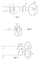
- Fig. 1 shows schematically an example of a system for passive ion therapy in which the invention may be implemented.
- a patient 1 that is to be subjected to ion therapy is shown schematically to the right in Fig. 1 .
- a region of interest ROI, or target 3 within the patient 1 represents the organ or other tissue that is to receive the radiotherapy.
- the maximum width of the target 3 is marked as w.
- a radiation source 5 provides an ion beam 7 having a sufficient energy to achieve the desired maximum range, typically reaching to the distal target 3 edge.
- one or two scattering devices (not shown) is arranged to create a broad field of radiation.
- a uniform scanning technique or wobbling may be used to create a broad field.
- scattering devices are not needed.
- a block and/or a compensator may be used to make an energy layer conform to the shape of the target. The dose is subsequently shaped to the target, that is, the region of interest, using passive devices.
- a range modulator 9 is arranged, in order to create the spread out Bragg peak as will be discussed in more detail in connection with Fig. 4 .
- the range modulator 9 determines the width w (along the beam direction) of the SOBP, which should be wide enough to cover the area of the target 3.
- a block 11 is arranged to shape the beam laterally.
- the target 3 typically has an irregular shape so that the water equivalent distance to the distal edge of the target will vary over the target. For example, in Fig.
- the lower portion of the target 3 extends further into the patient's body 1 than the upper portion.
- the patient geometry will also affect the (water equivalent) distance to the target.
- the body tissues are assumed to have the same properties as water, whereas bone or air pockets will affect the distance in different ways.
- a bone region in the beam path will for example increase the water equivalent depth, while an air cavity will reduce it, as compared to the geometrical distance.
- the beam energy is chosen so that the maximum ion beam range agrees with the most distal point on the target.
- a range compensator 15 is introduced to control the local range over the cross-section of the ion beam.
- the thickness of the range compensator varies across the beam trajectory in a way well known in the art to adapt the beam energy to the distal end of the target in each point.
- the range compensator 15 is arranged to shorten the range of the ion beam to a different degree in different points of the range compensator, so that in any point of the ROI the ion beam will reach as far as the distal end of the ROI.
- a block 11 and a range compensator 15 may also be used during a pencil beam scanning treatment.
- the ion beam is created by means of a large number of small pencil beams with different positions, ranges and intensities.
- This scanning technique gives the possibility to conform the dose well to the target. Therefore, the block is mainly used for sharpening the penumbra, that is, the lateral edges of the beam.
- the range compensator 15 may be used in this case to ensure that the highest energy layer coincides with the distal edge of the target 3.
- the aim of the radiation therapy is to provide a uniform yet conformal dose to the target 3 and as little radiation as possible outside of the target. This may be difficult because of beam spread. Heterogeneous patient geometries and complex target shapes will add to the difficulties. In some particularly complex situations two or more radiation fields are patched and/or matched together to provide a uniform dose to the entire target.
- Fig. 2 shows, schematically, a patient 21 comprising a target ROI 23 where part of the target 23 is blocked by a critical organ 24, which is to receive no radiation. The beam must be shaped such that no radiation reaches the critical organ 24 yet the whole target 23 should be treated.
- first through field 27 and a second field 29 must be patched together as shown in Fig. 2 .
- the first through field 27 is illustrated in Fig. 2 by two dotted vertical lines and the second field 29 is illustrated by two dashed horizontal lines.
- second field 29 is shaped in such a way that its distal edge will coincide with a lateral edge of the first field 27 to form an L shape, but even more complex shapes may be necessary in some cases. Because of the difference in dose gradient, it is common that the dose distribution in the border area between the first and the second field is not uniform. Instead the border will normally contain hot and cold spots, which will affect the treatment negatively.
- Fig. 3 illustrates a setup in which this can be applied.
- a patient 31 has a target ROI 33 which is to receive a target dose of ion radiation represented by two horizontal dashed lines 34.
- a target ROI 33 which is to receive a target dose of ion radiation represented by two horizontal dashed lines 34.
- two structures affect the water equivalent distance to the tumour: a bone structure 35 which will add to the water equivalent distance and an air cavity 36 which will reduce the water equivalent distance.
- a range compensator 38 is arranged to control the range of the ion beam to match the water equivalent depth. In the areas where the beam will only pass through soft tissue, the range compensator has a first thickness w1.
- the range compensator 38 has an area in which it is thinner than the first thickness w1, matching the area of the bone structure 35, to compensate for the increased water equivalent distance in this area.
- the range compensator 38 also has an area in which it is thicker than w1, matching the area of the air cavity 36, to compensate for the reduced water equivalent distance in this area.
- Fig. 4 illustrates schematically the spread out Bragg peak SOBP of a proton beam within a patient in terms of the relative dose as a function of depth.
- the dose increases from a plateau region to a maximum, which is constant over a distance w. After the spread out Bragg peak the dose will fall to zero within a short distance.
- the maximum range of the beam is denoted as R.
- the area of the maximum dose should coincide with the target width as shown in Fig. 1 , that is, the maximum emitted energy should occur when the proton beam travels through the target, after which the emitted energy should fall to zero as soon as possible.
- the depth dose shape for other ions is similar to the proton case, except that there will be a low dose tail after the SOBP resulting from nuclear fragments.
- the range of the beam and the design of the passive devices may be varied. Traditionally this is done by forward planning methods, by computing the design of the passive devices trough ray tracing of the patient geometry.
- the maximum range R of the target along the direction of the beam is computed by tracing the water equivalent depths of the distal target edge for all points, i, within the beam.
- the beam energy is then chosen so that the maximum range of the beam is equal to, or slightly larger than, the maximum range R of the target.
- the maximum width w of the target along the direction of the beam is computed by tracing the water equivalent depths of the distal and proximal target edges for all points, i, within the beam.
- the range modulator is then chosen so that its corresponding SOBP width is equal to, or slightly larger than, the maximum target width.
- a block contour For determining the block contour, traditionally all parts of the beam are traced, registering if the target is hit or not, thus finding where the target edge is situated. Due to beam spread the dose will drop at the beam edge, resulting in lower dose at the target edge. This is accounted for by expanding the block contour laterally, typically by 0.5 - 1 cm.
- a block contour may range from a few cm up to 20-30 cm across, depending on the size of the target area.
- compensator thickness i maximum beam range - distal edge i
- an inverse planning algorithm is used for determining the final shape of the passive devices using dose based optimization.
- different optimization variables are defined for the SOBP range and each of the passive devices, that is, the range modulator, the block and the range compensator.
- the optimization problem is specified by setting up a number of dose optimization functions. With the method according to the invention all devices can be optimized simultaneously.
- the method includes in a first step S41 setting the dose optimization functions and giving them weights, usually including a minimum and maximum dose in the target and a maximum dose in one or more critical risk organs.
- the combination of the weighted dose optimization functions results in the objective function, which is used to evaluate the dose distribution.
- step S42 an initial set of values for the optimization variables are set and in step S43 the initial resulting dose distribution for this initial set of values is determined.
- the possible optimization variables for the different devices will be discussed below.
- step S44 the objective function is evaluated by comparing the current dose distribution to the dose objectives, and in step S45 it is determined if the optimization should continue. If yes, the method continues with step S46, otherwise the method ends. Preferably, the optimization continues until the dose distribution satisfies the dose objectives within a certain tolerance. This typically means that the resulting dose to the whole target will be above the minimum dose and the resulting dose to any organ at risk will be below the maximum dose for this organ.
- step S46 the derivative of the objective function with respect to the optimization variables are computed. This can be used to determine the best modification of the optimization variables, described in the next step, although the modification may also be determined in other ways. Details of the derivative computation will be discussed below.
- step S47 at least one of the variable values is varied to produce a modified value set.
- the resulting dose distribution is computed for the modified set of variable values and the objective function is evaluated with respect to this new dose, i.e. a repetition of step S43 and S44.
- steps S43 - S47 are repeated a number of times, until it is determined in step S46 that the current resulting dose distribution matches the dose objective within a specified tolerance. In that case the last current value set is selected for use in the radiotherapy treatment.
- the optimization may be continued until the dose distribution substantially does not improve for each iteration, or until a number of iterations have been performed.
- steps S43 - S47 may be repeated a preselected number of times and, among the value sets that have been evaluated, the value set resulting in a dose distribution that best matches the dose objective may be selected.
- the optimization variables include the range and width of the SOBP.
- the SOBP range and width should be treated as continuous. In practice this means that they should be changed by very small increments in step S47.
- the width may have to be truncated to the next larger range modulator width when finalizing the optimization.
- optimization method using derivatives has been described above, other optimization methods may be used instead, for example an optimization method based on simulated annealing.
- the optimization variables for block aperture 13 optimization are expressed as an opening ratio matrix, where each pixel has a value between 0 (completely covered) and 1 (completely open).
- a pixel value between 0 and 1 means that the pixel is partly covered by the block contour. This leads to the requirement that partly covered pixels must lie on the edge of the open part, with completely covered pixels on the outside.
- the derivative of dose with respect to opening ratio is equal to the dose contribution from that pixel, since an increase in the opening ration will result in a proportionally equal increase of dose.
- the optimization variables for block aperture optimization are the positions of all vertices in the block contour polygon. Each vertex may move in the x and y direction. If using an optimization algorithm which is using derivatives, the derivative of dose with respect to the vertex position may be computed using finite elements, i.e. as the difference in dose between a small shift in the x and y position of the vertex.
- the optimization variables are the compensator thickness values in all pixels of the compensator matrix.
- each pixel of the compensator matrix may be set individually to allow maximum flexibility of the optimization algorithm.
- the derivative needs to be computed for each compensator pixel in each iteration.
- a corresponding dose distribution for a number of compensator thicknesses in each pixel should be precomputed and cached so that the computation does not have to be performed for each dose planning procedure.
- the derivative computation will be a matter of adding and subtracting cached dose distributions.
- a suitable range of compensator thicknesses may be +/- 1 cm in steps of 1 mm.
- the dose derivatives can be used to determine the best modification of the variables in step S47, however they are not necessary for all optimization algorithms.
- the passive devices 9, 11, 15 can be optimized using robust optimization. This means that their shapes are optimized so that the dose is optimal for a number of scenarios that spans the space of all plausible range and setup errors, not just the nominal scenario.
- Robust optimization takes into account uncertainties regarding for example the exact position of the patient, or the actual range of the beam
- FIG. 6 is a schematic representation of a computer system in which the inventive method may be performed.
- a computer 51 comprises a processor 53, a data memory 54 and a program memory 55.
- a user input means 58 is also present, in the form of a keyboard, a mouse, a joystick, voice recognition means or any other available user input means.
- a treatment plan, one or more value sets and one or more objective functions are found in the data memory 54, as well as the tolerance level used in step S45 above.
- the data in the data memory may be generated in the computer 51, entered by means of the user input means or received from another storage means, in any way known in the art.
- the data memory 54 is only shown schematically. There may be several data memory units, each holding one or more different types of data, for example, one data memory for the value set, one for the objective function, etc.
- the program memory 55 holds a computer program arranged to control the processor to perform the optimization as defined in Fig. 5 . It will be understood that not all of the steps of the method of Fig. 5 are necessarily performed in the computer 51.
Landscapes
- Health & Medical Sciences (AREA)
- Engineering & Computer Science (AREA)
- Biomedical Technology (AREA)
- Pathology (AREA)
- Nuclear Medicine, Radiotherapy & Molecular Imaging (AREA)
- Radiology & Medical Imaging (AREA)
- Life Sciences & Earth Sciences (AREA)
- Animal Behavior & Ethology (AREA)
- General Health & Medical Sciences (AREA)
- Public Health (AREA)
- Veterinary Medicine (AREA)
- Radiation-Therapy Devices (AREA)
Priority Applications (5)
| Application Number | Priority Date | Filing Date | Title |
|---|---|---|---|
| EP15173971.1A EP3108932B1 (fr) | 2015-06-26 | 2015-06-26 | Méthode, programme informatique et un système pour optimiser le traitement de radiothérapie |
| US15/533,420 US10315047B2 (en) | 2015-06-26 | 2016-06-23 | Method, computer program and system for optimizing radiotherapy treatment |
| CN201680002883.7A CN107073289B (zh) | 2015-06-25 | 2016-06-23 | 用于优化放射治疗计划的方法、载体和计算机系统 |
| PCT/EP2016/064551 WO2016207286A1 (fr) | 2015-06-25 | 2016-06-23 | Procédé, programme informatique et système optimisant le traitement par radiothérapie |
| JP2017511331A JP6375055B2 (ja) | 2015-06-25 | 2016-06-23 | 放射線治療を最適化するための方法、コンピュータプログラムおよびシステム |
Applications Claiming Priority (1)
| Application Number | Priority Date | Filing Date | Title |
|---|---|---|---|
| EP15173971.1A EP3108932B1 (fr) | 2015-06-26 | 2015-06-26 | Méthode, programme informatique et un système pour optimiser le traitement de radiothérapie |
Publications (2)
| Publication Number | Publication Date |
|---|---|
| EP3108932A1 true EP3108932A1 (fr) | 2016-12-28 |
| EP3108932B1 EP3108932B1 (fr) | 2018-01-31 |
Family
ID=53765053
Family Applications (1)
| Application Number | Title | Priority Date | Filing Date |
|---|---|---|---|
| EP15173971.1A Active EP3108932B1 (fr) | 2015-06-25 | 2015-06-26 | Méthode, programme informatique et un système pour optimiser le traitement de radiothérapie |
Country Status (5)
| Country | Link |
|---|---|
| US (1) | US10315047B2 (fr) |
| EP (1) | EP3108932B1 (fr) |
| JP (1) | JP6375055B2 (fr) |
| CN (1) | CN107073289B (fr) |
| WO (1) | WO2016207286A1 (fr) |
Cited By (4)
| Publication number | Priority date | Publication date | Assignee | Title |
|---|---|---|---|---|
| WO2019025460A1 (fr) * | 2017-07-31 | 2019-02-07 | Koninklijke Philips N.V. | Mécanisme de réglage pour les objectifs liés aux oar et cibles pendant une optimisation |
| EP3669941A1 (fr) * | 2018-12-20 | 2020-06-24 | RaySearch Laboratories AB | Système et procédé de planification de traitement par radiothérapie ionique passif |
| EP3943152A1 (fr) * | 2020-07-20 | 2022-01-26 | RaySearch Laboratories AB | Évaluation de plan ou de planification de traitement robuste |
| US20220040500A1 (en) * | 2018-12-20 | 2022-02-10 | Raysearch Laboratories Ab | System and method for passive ion radiotherapy treatment planning and delivery |
Families Citing this family (32)
| Publication number | Priority date | Publication date | Assignee | Title |
|---|---|---|---|---|
| US20150213232A1 (en) | 2014-01-29 | 2015-07-30 | Muses Labs, Inc. | Interactive and analytical system that provides a dynamic tool for therapies to prevent and cure dementia-related diseases |
| US11257593B2 (en) | 2014-01-29 | 2022-02-22 | Umethod Health, Inc. | Interactive and analytical system that provides a dynamic tool for therapies to prevent and cure dementia-related diseases |
| US9855445B2 (en) | 2016-04-01 | 2018-01-02 | Varian Medical Systems, Inc. | Radiation therapy systems and methods for delivering doses to a target volume |
| WO2017216219A1 (fr) * | 2016-06-14 | 2017-12-21 | Koninklijke Philips N.V. | Optimisation de faisceau large robuste pour thérapie par protons |
| EP3654976A1 (fr) | 2017-07-21 | 2020-05-27 | Varian Medical Systems, Inc. | Procédés d'utilisation de rayonnement à débit de dose ultra élevé et d'agents thérapeutiques |
| US10183179B1 (en) | 2017-07-21 | 2019-01-22 | Varian Medical Systems, Inc. | Triggered treatment systems and methods |
| US11590364B2 (en) | 2017-07-21 | 2023-02-28 | Varian Medical Systems International Ag | Material inserts for radiation therapy |
| US10549117B2 (en) | 2017-07-21 | 2020-02-04 | Varian Medical Systems, Inc | Geometric aspects of radiation therapy planning and treatment |
| US10092774B1 (en) | 2017-07-21 | 2018-10-09 | Varian Medical Systems International, AG | Dose aspects of radiation therapy planning and treatment |
| US11712579B2 (en) | 2017-07-21 | 2023-08-01 | Varian Medical Systems, Inc. | Range compensators for radiation therapy |
| US10843011B2 (en) | 2017-07-21 | 2020-11-24 | Varian Medical Systems, Inc. | Particle beam gun control systems and methods |
| WO2019033105A1 (fr) * | 2017-08-11 | 2019-02-14 | The Regents Of The University Of California | Détermination de propriétés de tissu pour une radiothérapie à particules chargées |
| EP3710111B1 (fr) | 2017-11-16 | 2021-12-29 | Varian Medical Systems, Inc. | Sortie de faisceau améliorée et mise en forme de champ dynamique destinés à un système de radiothérapie |
| US10910188B2 (en) | 2018-07-25 | 2021-02-02 | Varian Medical Systems, Inc. | Radiation anode target systems and methods |
| WO2020097800A1 (fr) * | 2018-11-13 | 2020-05-22 | 西安大医集团有限公司 | Filtre optique, appareil de balayage de rayonnement et procédé de balayage de rayonnement |
| EP3669939B1 (fr) * | 2018-12-20 | 2025-10-29 | RaySearch Laboratories AB | Procédé, programme informatique et système informatique pour l'optimisation d'au moins un plan de traitement |
| US10814144B2 (en) | 2019-03-06 | 2020-10-27 | Varian Medical Systems, Inc. | Radiation treatment based on dose rate |
| US11116995B2 (en) | 2019-03-06 | 2021-09-14 | Varian Medical Systems, Inc. | Radiation treatment planning based on dose rate |
| US11103727B2 (en) | 2019-03-08 | 2021-08-31 | Varian Medical Systems International Ag | Model based PBS optimization for flash therapy treatment planning and oncology information system |
| US11090508B2 (en) | 2019-03-08 | 2021-08-17 | Varian Medical Systems Particle Therapy Gmbh & Co. Kg | System and method for biological treatment planning and decision support |
| US10918886B2 (en) | 2019-06-10 | 2021-02-16 | Varian Medical Systems, Inc. | Flash therapy treatment planning and oncology information system having dose rate prescription and dose rate mapping |
| US11291859B2 (en) | 2019-10-03 | 2022-04-05 | Varian Medical Systems, Inc. | Radiation treatment planning for delivering high dose rates to spots in a target |
| US12390662B2 (en) | 2020-04-02 | 2025-08-19 | Siemens Healthineers International Ag | System and method for proton therapy treatment planning with proton energy and spot optimization |
| US11865361B2 (en) | 2020-04-03 | 2024-01-09 | Varian Medical Systems, Inc. | System and method for scanning pattern optimization for flash therapy treatment planning |
| US11541252B2 (en) | 2020-06-23 | 2023-01-03 | Varian Medical Systems, Inc. | Defining dose rate for pencil beam scanning |
| US11957934B2 (en) | 2020-07-01 | 2024-04-16 | Siemens Healthineers International Ag | Methods and systems using modeling of crystalline materials for spot placement for radiation therapy |
| US12064645B2 (en) | 2020-07-02 | 2024-08-20 | Siemens Healthineers International Ag | Methods and systems used for planning radiation treatment |
| EP3957361B1 (fr) * | 2020-08-21 | 2024-12-04 | RaySearch Laboratories AB | Dispositif statique à utiliser dans un traitement par radiothérapie et procédé de conception d'un tel dispositif |
| JP2024513987A (ja) * | 2021-04-13 | 2024-03-27 | ザ ニューヨーク プロトン センター | Flash放射線療法システム及び使用方法 |
| EP4082608B1 (fr) * | 2021-04-26 | 2023-06-07 | RaySearch Laboratories AB | Dispositif statique à utiliser dans un traitement par radiothérapie et procédé de conception d'un tel dispositif |
| EP4327864B1 (fr) * | 2022-08-24 | 2025-01-22 | Ion Beam Applications | Contrôle de qualité hors ligne d'un dispositif de mise en forme du faisceau pour la radiothérapie |
| EP4678227A1 (fr) * | 2024-07-12 | 2026-01-14 | RaySearch Laboratories AB | Procédé d'optimisation d'un plan de traitement par rayonnement |
Citations (3)
| Publication number | Priority date | Publication date | Assignee | Title |
|---|---|---|---|---|
| US20040165696A1 (en) * | 1999-11-05 | 2004-08-26 | Lee Eva K. | Systems and methods for global optimization of treatment planning for external beam radiation therapy |
| US20060045238A1 (en) * | 2004-08-25 | 2006-03-02 | Prowess, Inc. | Method for intensity modulated radiation treatment using independent collimator jaws |
| WO2008114159A1 (fr) | 2007-03-19 | 2008-09-25 | Koninklijke Philips Electronics N.V. | Optimisation de traitement |
Family Cites Families (2)
| Publication number | Priority date | Publication date | Assignee | Title |
|---|---|---|---|---|
| JP3932667B2 (ja) * | 1998-04-16 | 2007-06-20 | 株式会社日立製作所 | 陽子線治療計画システム |
| CN101247852B (zh) * | 2005-07-25 | 2011-12-07 | 卡尔·奥托 | 用于计划和供给放射治疗的方法和装置 |
-
2015
- 2015-06-26 EP EP15173971.1A patent/EP3108932B1/fr active Active
-
2016
- 2016-06-23 CN CN201680002883.7A patent/CN107073289B/zh active Active
- 2016-06-23 WO PCT/EP2016/064551 patent/WO2016207286A1/fr not_active Ceased
- 2016-06-23 US US15/533,420 patent/US10315047B2/en active Active
- 2016-06-23 JP JP2017511331A patent/JP6375055B2/ja active Active
Patent Citations (3)
| Publication number | Priority date | Publication date | Assignee | Title |
|---|---|---|---|---|
| US20040165696A1 (en) * | 1999-11-05 | 2004-08-26 | Lee Eva K. | Systems and methods for global optimization of treatment planning for external beam radiation therapy |
| US20060045238A1 (en) * | 2004-08-25 | 2006-03-02 | Prowess, Inc. | Method for intensity modulated radiation treatment using independent collimator jaws |
| WO2008114159A1 (fr) | 2007-03-19 | 2008-09-25 | Koninklijke Philips Electronics N.V. | Optimisation de traitement |
Non-Patent Citations (1)
| Title |
|---|
| LI ET AL.: "A novel patch-field design using an optimized grid filter for passively scattered proton beams", PHYS. MED. BIOL., vol. 52, 2007, pages N265 - N275, XP020112932, DOI: doi:10.1088/0031-9155/52/12/N01 |
Cited By (14)
| Publication number | Priority date | Publication date | Assignee | Title |
|---|---|---|---|---|
| WO2019025460A1 (fr) * | 2017-07-31 | 2019-02-07 | Koninklijke Philips N.V. | Mécanisme de réglage pour les objectifs liés aux oar et cibles pendant une optimisation |
| CN111050848A (zh) * | 2017-07-31 | 2020-04-21 | 皇家飞利浦有限公司 | 在优化期间用于oar和靶目标的调谐机制 |
| CN111050848B (zh) * | 2017-07-31 | 2023-03-14 | 皇家飞利浦有限公司 | 在优化期间用于oar和靶目标的调谐方法和介质 |
| US11517766B2 (en) | 2017-07-31 | 2022-12-06 | Koninklijke Philips N.V. | Tuning mechanism for OAR and target objectives during optimization |
| JP2022514092A (ja) * | 2018-12-20 | 2022-02-09 | レイサーチ ラボラトリーズ,エービー | パッシブイオン放射線治療計画のためのシステムおよび方法 |
| US20220040500A1 (en) * | 2018-12-20 | 2022-02-10 | Raysearch Laboratories Ab | System and method for passive ion radiotherapy treatment planning and delivery |
| WO2020127659A1 (fr) * | 2018-12-20 | 2020-06-25 | Raysearch Laboratories Ab | Système et méthode de planification d'un traitement par radiothérapie ionique passive |
| EP3669941A1 (fr) * | 2018-12-20 | 2020-06-24 | RaySearch Laboratories AB | Système et procédé de planification de traitement par radiothérapie ionique passif |
| US11969608B2 (en) | 2018-12-20 | 2024-04-30 | Raysearch Laboratories Ab | System and method for passive ion radiotherapy treatment planning and delivery |
| EP3669940B1 (fr) * | 2018-12-20 | 2024-05-01 | RaySearch Laboratories AB | Système et procédé de planification et d'administration de traitement radiothérapeutique ionique passif |
| WO2022017684A1 (fr) * | 2020-07-20 | 2022-01-27 | Raysearch Laboratories Ab | Évaluation fiable de planification ou de plan de traitement |
| EP3943152A1 (fr) * | 2020-07-20 | 2022-01-26 | RaySearch Laboratories AB | Évaluation de plan ou de planification de traitement robuste |
| CN115702021A (zh) * | 2020-07-20 | 2023-02-14 | 光线搜索实验室公司 | 稳健治疗规划或计划评估 |
| US12285629B2 (en) | 2020-07-20 | 2025-04-29 | Raysearch Laboratories Ab (Publ) | Robust treatment planning or plan evaluation |
Also Published As
| Publication number | Publication date |
|---|---|
| JP6375055B2 (ja) | 2018-08-15 |
| WO2016207286A1 (fr) | 2016-12-29 |
| US20170333733A1 (en) | 2017-11-23 |
| US10315047B2 (en) | 2019-06-11 |
| CN107073289A (zh) | 2017-08-18 |
| JP2018510664A (ja) | 2018-04-19 |
| EP3108932B1 (fr) | 2018-01-31 |
| CN107073289B (zh) | 2019-02-01 |
Similar Documents
| Publication | Publication Date | Title |
|---|---|---|
| US10315047B2 (en) | Method, computer program and system for optimizing radiotherapy treatment | |
| CN109414592B (zh) | 用于放射疗法治疗计划的计算机系统 | |
| CN103157196B (zh) | 用于粒子治疗的辐照规划方法和辐照规划装置 | |
| CN116457061A (zh) | 粒子弧治疗计划 | |
| US20190290931A1 (en) | Robust broad beam optimization for proton therapy | |
| US12147734B2 (en) | Static device for use in radiotherapy treatment and design method for such a device | |
| US11969608B2 (en) | System and method for passive ion radiotherapy treatment planning and delivery | |
| JP2014054346A (ja) | 放射線治療計画装置 | |
| EP4292648B1 (fr) | Positionnement de point basé sur des objectifs de contrainte et d'optimisation d'unité de surveillance minimale (mu) pour un système de radiothérapie | |
| JP5401391B2 (ja) | 粒子線治療計画装置及び治療計画方法 | |
| CN116920285A (zh) | 辐射治疗计划中的监测单元优化约束 | |
| CN113877082B (zh) | 用于计划辐射处理的方法和系统 | |
| EP4252837A1 (fr) | Modélisation d'effet d'étalement de dose pour plan de traitement par rayonnement | |
| CN107961447B (zh) | 一种放疗计划的获得方法和装置 | |
| US11798674B2 (en) | Static device for use in radiotherapy treatment and design method for such a device | |
| JP7357059B2 (ja) | パッシブイオン放射線治療計画のためのシステムおよび方法 | |
| Fjæra et al. | Implementation of a double scattering nozzle for Monte Carlo recalculation of proton plans with variable relative biological effectiveness | |
| US11052265B2 (en) | Fluence map optimization for field-in-field radiation therapy | |
| EP4427802A1 (fr) | Procédés et systèmes de planification de traitement pour commander l'uniformité de distributions de dose de champs de radiothérapie |
Legal Events
| Date | Code | Title | Description |
|---|---|---|---|
| PUAI | Public reference made under article 153(3) epc to a published international application that has entered the european phase |
Free format text: ORIGINAL CODE: 0009012 |
|
| 17P | Request for examination filed |
Effective date: 20160324 |
|
| AK | Designated contracting states |
Kind code of ref document: A1 Designated state(s): AL AT BE BG CH CY CZ DE DK EE ES FI FR GB GR HR HU IE IS IT LI LT LU LV MC MK MT NL NO PL PT RO RS SE SI SK SM TR |
|
| AX | Request for extension of the european patent |
Extension state: BA ME |
|
| GRAP | Despatch of communication of intention to grant a patent |
Free format text: ORIGINAL CODE: EPIDOSNIGR1 |
|
| GRAJ | Information related to disapproval of communication of intention to grant by the applicant or resumption of examination proceedings by the epo deleted |
Free format text: ORIGINAL CODE: EPIDOSDIGR1 |
|
| INTG | Intention to grant announced |
Effective date: 20170217 |
|
| INTC | Intention to grant announced (deleted) | ||
| RIN1 | Information on inventor provided before grant (corrected) |
Inventor name: GLIMELIUS, LARS Inventor name: ERSMARK, TORE Inventor name: JANSON, MARTIN |
|
| GRAS | Grant fee paid |
Free format text: ORIGINAL CODE: EPIDOSNIGR3 |
|
| GRAP | Despatch of communication of intention to grant a patent |
Free format text: ORIGINAL CODE: EPIDOSNIGR1 |
|
| INTG | Intention to grant announced |
Effective date: 20170530 |
|
| GRAA | (expected) grant |
Free format text: ORIGINAL CODE: 0009210 |
|
| AK | Designated contracting states |
Kind code of ref document: B1 Designated state(s): AL AT BE BG CH CY CZ DE DK EE ES FI FR GB GR HR HU IE IS IT LI LT LU LV MC MK MT NL NO PL PT RO RS SE SI SK SM TR |
|
| REG | Reference to a national code |
Ref country code: GB Ref legal event code: FG4D Ref country code: CH Ref legal event code: EP |
|
| REG | Reference to a national code |
Ref country code: AT Ref legal event code: REF Ref document number: 966804 Country of ref document: AT Kind code of ref document: T Effective date: 20180215 |
|
| REG | Reference to a national code |
Ref country code: IE Ref legal event code: FG4D |
|
| REG | Reference to a national code |
Ref country code: DE Ref legal event code: R096 Ref document number: 602015007690 Country of ref document: DE |
|
| REG | Reference to a national code |
Ref country code: NL Ref legal event code: MP Effective date: 20180131 |
|
| REG | Reference to a national code |
Ref country code: LT Ref legal event code: MG4D |
|
| REG | Reference to a national code |
Ref country code: AT Ref legal event code: MK05 Ref document number: 966804 Country of ref document: AT Kind code of ref document: T Effective date: 20180131 |
|
| REG | Reference to a national code |
Ref country code: FR Ref legal event code: PLFP Year of fee payment: 4 |
|
| PG25 | Lapsed in a contracting state [announced via postgrant information from national office to epo] |
Ref country code: ES Free format text: LAPSE BECAUSE OF FAILURE TO SUBMIT A TRANSLATION OF THE DESCRIPTION OR TO PAY THE FEE WITHIN THE PRESCRIBED TIME-LIMIT Effective date: 20180131 Ref country code: NL Free format text: LAPSE BECAUSE OF FAILURE TO SUBMIT A TRANSLATION OF THE DESCRIPTION OR TO PAY THE FEE WITHIN THE PRESCRIBED TIME-LIMIT Effective date: 20180131 Ref country code: NO Free format text: LAPSE BECAUSE OF FAILURE TO SUBMIT A TRANSLATION OF THE DESCRIPTION OR TO PAY THE FEE WITHIN THE PRESCRIBED TIME-LIMIT Effective date: 20180430 Ref country code: LT Free format text: LAPSE BECAUSE OF FAILURE TO SUBMIT A TRANSLATION OF THE DESCRIPTION OR TO PAY THE FEE WITHIN THE PRESCRIBED TIME-LIMIT Effective date: 20180131 Ref country code: HR Free format text: LAPSE BECAUSE OF FAILURE TO SUBMIT A TRANSLATION OF THE DESCRIPTION OR TO PAY THE FEE WITHIN THE PRESCRIBED TIME-LIMIT Effective date: 20180131 Ref country code: FI Free format text: LAPSE BECAUSE OF FAILURE TO SUBMIT A TRANSLATION OF THE DESCRIPTION OR TO PAY THE FEE WITHIN THE PRESCRIBED TIME-LIMIT Effective date: 20180131 |
|
| PG25 | Lapsed in a contracting state [announced via postgrant information from national office to epo] |
Ref country code: BG Free format text: LAPSE BECAUSE OF FAILURE TO SUBMIT A TRANSLATION OF THE DESCRIPTION OR TO PAY THE FEE WITHIN THE PRESCRIBED TIME-LIMIT Effective date: 20180430 Ref country code: GR Free format text: LAPSE BECAUSE OF FAILURE TO SUBMIT A TRANSLATION OF THE DESCRIPTION OR TO PAY THE FEE WITHIN THE PRESCRIBED TIME-LIMIT Effective date: 20180501 Ref country code: PL Free format text: LAPSE BECAUSE OF FAILURE TO SUBMIT A TRANSLATION OF THE DESCRIPTION OR TO PAY THE FEE WITHIN THE PRESCRIBED TIME-LIMIT Effective date: 20180131 Ref country code: AT Free format text: LAPSE BECAUSE OF FAILURE TO SUBMIT A TRANSLATION OF THE DESCRIPTION OR TO PAY THE FEE WITHIN THE PRESCRIBED TIME-LIMIT Effective date: 20180131 Ref country code: LV Free format text: LAPSE BECAUSE OF FAILURE TO SUBMIT A TRANSLATION OF THE DESCRIPTION OR TO PAY THE FEE WITHIN THE PRESCRIBED TIME-LIMIT Effective date: 20180131 Ref country code: SE Free format text: LAPSE BECAUSE OF FAILURE TO SUBMIT A TRANSLATION OF THE DESCRIPTION OR TO PAY THE FEE WITHIN THE PRESCRIBED TIME-LIMIT Effective date: 20180131 Ref country code: IS Free format text: LAPSE BECAUSE OF FAILURE TO SUBMIT A TRANSLATION OF THE DESCRIPTION OR TO PAY THE FEE WITHIN THE PRESCRIBED TIME-LIMIT Effective date: 20180531 Ref country code: RS Free format text: LAPSE BECAUSE OF FAILURE TO SUBMIT A TRANSLATION OF THE DESCRIPTION OR TO PAY THE FEE WITHIN THE PRESCRIBED TIME-LIMIT Effective date: 20180131 |
|
| PG25 | Lapsed in a contracting state [announced via postgrant information from national office to epo] |
Ref country code: IT Free format text: LAPSE BECAUSE OF FAILURE TO SUBMIT A TRANSLATION OF THE DESCRIPTION OR TO PAY THE FEE WITHIN THE PRESCRIBED TIME-LIMIT Effective date: 20180131 Ref country code: AL Free format text: LAPSE BECAUSE OF FAILURE TO SUBMIT A TRANSLATION OF THE DESCRIPTION OR TO PAY THE FEE WITHIN THE PRESCRIBED TIME-LIMIT Effective date: 20180131 Ref country code: EE Free format text: LAPSE BECAUSE OF FAILURE TO SUBMIT A TRANSLATION OF THE DESCRIPTION OR TO PAY THE FEE WITHIN THE PRESCRIBED TIME-LIMIT Effective date: 20180131 |
|
| REG | Reference to a national code |
Ref country code: DE Ref legal event code: R097 Ref document number: 602015007690 Country of ref document: DE |
|
| PG25 | Lapsed in a contracting state [announced via postgrant information from national office to epo] |
Ref country code: DK Free format text: LAPSE BECAUSE OF FAILURE TO SUBMIT A TRANSLATION OF THE DESCRIPTION OR TO PAY THE FEE WITHIN THE PRESCRIBED TIME-LIMIT Effective date: 20180131 Ref country code: SM Free format text: LAPSE BECAUSE OF FAILURE TO SUBMIT A TRANSLATION OF THE DESCRIPTION OR TO PAY THE FEE WITHIN THE PRESCRIBED TIME-LIMIT Effective date: 20180131 Ref country code: CZ Free format text: LAPSE BECAUSE OF FAILURE TO SUBMIT A TRANSLATION OF THE DESCRIPTION OR TO PAY THE FEE WITHIN THE PRESCRIBED TIME-LIMIT Effective date: 20180131 Ref country code: SK Free format text: LAPSE BECAUSE OF FAILURE TO SUBMIT A TRANSLATION OF THE DESCRIPTION OR TO PAY THE FEE WITHIN THE PRESCRIBED TIME-LIMIT Effective date: 20180131 |
|
| PLBE | No opposition filed within time limit |
Free format text: ORIGINAL CODE: 0009261 |
|
| STAA | Information on the status of an ep patent application or granted ep patent |
Free format text: STATUS: NO OPPOSITION FILED WITHIN TIME LIMIT |
|
| 26N | No opposition filed |
Effective date: 20181102 |
|
| REG | Reference to a national code |
Ref country code: CH Ref legal event code: PL |
|
| PG25 | Lapsed in a contracting state [announced via postgrant information from national office to epo] |
Ref country code: SI Free format text: LAPSE BECAUSE OF FAILURE TO SUBMIT A TRANSLATION OF THE DESCRIPTION OR TO PAY THE FEE WITHIN THE PRESCRIBED TIME-LIMIT Effective date: 20180131 |
|
| REG | Reference to a national code |
Ref country code: BE Ref legal event code: MM Effective date: 20180630 |
|
| REG | Reference to a national code |
Ref country code: IE Ref legal event code: MM4A |
|
| PG25 | Lapsed in a contracting state [announced via postgrant information from national office to epo] |
Ref country code: LU Free format text: LAPSE BECAUSE OF NON-PAYMENT OF DUE FEES Effective date: 20180626 Ref country code: MC Free format text: LAPSE BECAUSE OF FAILURE TO SUBMIT A TRANSLATION OF THE DESCRIPTION OR TO PAY THE FEE WITHIN THE PRESCRIBED TIME-LIMIT Effective date: 20180131 |
|
| PG25 | Lapsed in a contracting state [announced via postgrant information from national office to epo] |
Ref country code: IE Free format text: LAPSE BECAUSE OF NON-PAYMENT OF DUE FEES Effective date: 20180626 Ref country code: CH Free format text: LAPSE BECAUSE OF NON-PAYMENT OF DUE FEES Effective date: 20180630 Ref country code: LI Free format text: LAPSE BECAUSE OF NON-PAYMENT OF DUE FEES Effective date: 20180630 |
|
| PG25 | Lapsed in a contracting state [announced via postgrant information from national office to epo] |
Ref country code: BE Free format text: LAPSE BECAUSE OF NON-PAYMENT OF DUE FEES Effective date: 20180630 |
|
| PG25 | Lapsed in a contracting state [announced via postgrant information from national office to epo] |
Ref country code: MT Free format text: LAPSE BECAUSE OF NON-PAYMENT OF DUE FEES Effective date: 20180626 |
|
| PG25 | Lapsed in a contracting state [announced via postgrant information from national office to epo] |
Ref country code: TR Free format text: LAPSE BECAUSE OF FAILURE TO SUBMIT A TRANSLATION OF THE DESCRIPTION OR TO PAY THE FEE WITHIN THE PRESCRIBED TIME-LIMIT Effective date: 20180131 |
|
| PG25 | Lapsed in a contracting state [announced via postgrant information from national office to epo] |
Ref country code: PT Free format text: LAPSE BECAUSE OF FAILURE TO SUBMIT A TRANSLATION OF THE DESCRIPTION OR TO PAY THE FEE WITHIN THE PRESCRIBED TIME-LIMIT Effective date: 20180131 |
|
| PG25 | Lapsed in a contracting state [announced via postgrant information from national office to epo] |
Ref country code: RO Free format text: LAPSE BECAUSE OF FAILURE TO SUBMIT A TRANSLATION OF THE DESCRIPTION OR TO PAY THE FEE WITHIN THE PRESCRIBED TIME-LIMIT Effective date: 20180131 Ref country code: HU Free format text: LAPSE BECAUSE OF FAILURE TO SUBMIT A TRANSLATION OF THE DESCRIPTION OR TO PAY THE FEE WITHIN THE PRESCRIBED TIME-LIMIT; INVALID AB INITIO Effective date: 20150626 Ref country code: CY Free format text: LAPSE BECAUSE OF FAILURE TO SUBMIT A TRANSLATION OF THE DESCRIPTION OR TO PAY THE FEE WITHIN THE PRESCRIBED TIME-LIMIT Effective date: 20180131 Ref country code: MK Free format text: LAPSE BECAUSE OF NON-PAYMENT OF DUE FEES Effective date: 20180131 |
|
| P01 | Opt-out of the competence of the unified patent court (upc) registered |
Effective date: 20230731 |
|
| PGFP | Annual fee paid to national office [announced via postgrant information from national office to epo] |
Ref country code: DE Payment date: 20250617 Year of fee payment: 11 |
|
| PGFP | Annual fee paid to national office [announced via postgrant information from national office to epo] |
Ref country code: GB Payment date: 20250617 Year of fee payment: 11 |
|
| PGFP | Annual fee paid to national office [announced via postgrant information from national office to epo] |
Ref country code: FR Payment date: 20250618 Year of fee payment: 11 |