EP3108979B1 - Grain de poussée pour une presse d'extrusion - Google Patents
Grain de poussée pour une presse d'extrusion Download PDFInfo
- Publication number
- EP3108979B1 EP3108979B1 EP15173525.5A EP15173525A EP3108979B1 EP 3108979 B1 EP3108979 B1 EP 3108979B1 EP 15173525 A EP15173525 A EP 15173525A EP 3108979 B1 EP3108979 B1 EP 3108979B1
- Authority
- EP
- European Patent Office
- Prior art keywords
- dummy block
- groove
- filler ring
- wall portion
- block body
- Prior art date
- Legal status (The legal status is an assumption and is not a legal conclusion. Google has not performed a legal analysis and makes no representation as to the accuracy of the status listed.)
- Not-in-force
Links
Images


Classifications
-
- B—PERFORMING OPERATIONS; TRANSPORTING
- B21—MECHANICAL METAL-WORKING WITHOUT ESSENTIALLY REMOVING MATERIAL; PUNCHING METAL
- B21C—MANUFACTURE OF METAL SHEETS, WIRE, RODS, TUBES, PROFILES OR LIKE SEMI-MANUFACTURED PRODUCTS OTHERWISE THAN BY ROLLING; AUXILIARY OPERATIONS USED IN CONNECTION WITH METAL-WORKING WITHOUT ESSENTIALLY REMOVING MATERIAL
- B21C26/00—Rams or plungers for metal extruding; Discs therefor
Definitions
- the present invention relates to a dummy block for an extrusion press having a die, a container for receiving a billet to be extruded through the die, and an extrusion stem for exerting a pressure on the billet sufficient to extrude it through the die, said dummy block being positioned between the extrusion stem and the billet and comprising:
- the object of the present invention is to provide a dummy block of a less complicated design, which can be produced with a reduced consumption of structural material, simple mounting and at lower costs compared with the dummy blocks described in the prior art.
- Such a dummy block consists of few components (only two, apart from screws), and is of a very simple and axially compact design, reducing the required amount of structural material considerably.
- both of the groove sides of the dummy body and both of the matching sides of the filler ring are conical, they converge toward the bottom of the groove.
- the filler ring will expand radially when being pressed into the groove, and the sealing lip will consequently be expanded radially both by conical outer wall portion and by the conical inner wall portion of the filler ring.
- the central pressing surface is located in a first plane
- the peripheral pressing surface is located in a second plane parallel to the first plane but closer to the rear face of the dummy block body
- the filler ring has a pressing surface located in a position between said first and said second plane.
- the pressing surface of the filler ring is located in a third plane parallel to the two other planes described above. Thereby, most of the air is evacuated through said gap before the rear face of the deformed billet abuts the pressing surface of the filler ring and the pressing surface of said sealing lip. As soon as the pressure from the billet on the filler ring is sufficiently high, it presses the filler ring downward into the groove, thereby causing said sealing lip radially outside the groove to elastically expand radially to seal against the interior wall of the container. This design results in a delayed sealing effect which makes it possible for all air to come out during the compression.
- the rear face of the dummy block body is provided with at least one stepped through bore opening in the bottom of the groove
- the filler ring has a bottom surface provided with at least one threaded bore aligned with the stepped through bore of the dummy block body, and a screw extends through the stepped bore into the threaded bore to anchor the filler ring in the groove.
- the filler ring is prevented from falling out of the groove when handling the dummy block outside of the container.
- both the dummy block body and the filler ring have two or more such bores, which are equiangularly spaced from each other.
- a venting channel is provided for permitting air to escape from the bottom of the groove through the stepped bore and between the extrusion stem and the rear face of the dummy block body and out to a space radially outside the stem.
- the dummy block body preferably has a female receptor of a bayonet mount for receiving a mating male portion on the stem.
- the female receptor of a bayonet mount suitably has two or more equiangularly spaced internal cams for cooperation with two or more equiangularly spaced external cams on the male portion of the stem.
- the rear face of the dummy block body has at least one threaded bore located close to an outer circumference thereof, and the extrusion stem has a slot-shaped recess placed correspondingly to said at least one threaded bore, the recess permitting insertion and tightening of a machine screw having a head that prevents an involuntary uncoupling of the bayonet mount by being stopped by sides of the slot-shaped recess.
- the rear face of the dummy block body has two or more such threaded bores that are equiangularly spaced and the extrusion stem has two or more such slot-shaped recesses that are equiangularly spaced.
- the elastically deformable sealing lip formed radially outside the groove is stepped in its longitudinal direction and has a larger diameter at said front face than at said rear face, thereby, when under pressure, during the extrusion generating a sealing surface for sealing against the inside wall of the container lining.
- This sealing feature surceases once the billet is extruded and the pressure against the dummy block disappears; the elastically deformable sealing lip retakes its initial dimensions and permits a friction free retreat of the stem out of the container.
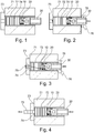
- Figs. 1-4 illustrates the working principle of the dummy block of the present invention by showing a starting sequence of an extrusion.
- the shown extrusion press has a container 71 with a lining 72, a die 73 and an extrusion stem 30 with a dummy block 20 for pressing a billet 74 in the container 71 through the die 73 to form an extruded profile 75.
- a billet 74 is placed in the container 71, which billet 74 is pressed against the die 73 by a central portion of the dummy block 2.
- Fig. 1 a billet 74 is placed in the container 71, which billet 74 is pressed against the die 73 by a central portion of the dummy block 2.
- the pressure from the extrusion stem 30 on the billet 74 is increased to cause a plastic deformation at the front of the billet 74, which expands radially and also starts to enter the die 73, so that air remaining in the extrusion compartment is forced backward to pass the dummy block 2 as there is no seal between the dummy block 2 and the lining 72.
- the escaping air is marked with reference numeral 76 in Figs. 2 and 3 .
- the material of the billet is preferably metal, including steel, aluminum, copper, zirconium, titanium, molybdenum, beryllium, vanadium, or niobium.
- the dummy block of the present invention is applicable primarily for hot extrusion, more preferably for metals at a temperature between 100 and 1300 °C.
- Figs. 5-10 show the invention more in detail.
- the extrusion stem 30, or more specifically an adapter 31 carried by the extrusion stem 30, is connected to the dummy block 2 by means of a first connecting member 32 of the adapter 31 mating with a second connecting member of the dummy block 2.
- the two connecting members suitably are a male member on the adapter 31 and a female member formed by a recess in the dummy block 2, and together they preferably form a bayonet coupling.
- any other suitable coupling may be used, e.g. threaded, pin locking system, etc.
- the dummy block 2 comprises a dummy block body 20 with a rear face 201 adapted to be connected to the extrusion stem 30, and a front face provided with a circular groove 40 defining a central pressing surface 21 for exerting a pressure on the billet 74.
- the dummy block body 20 has a peripheral annular pressing surface 281 for exerting a pressure on the billet 74.
- the peripheral annular pressing surface 281 is located on said elastically deformable sealing lip 28 formed radially outside the groove 40, and the sealing lip 28 is sufficiently elastically deformable to be pressed outward by the extrusion pressure to seal against an inside wall of the lining 72 in the container 71.
- the circular groove 40 has a radially inner wall portion 23, a radially outer wall portion 24, and a bottom 22; the outer wall portion 24 is conical to make the groove 40 open axially outward.
- the dummy block 2 also comprises said filler ring 10 adapted to fit in an upper part of the groove 40 while forming a gap 41 toward the bottom 22 of the groove 40.
- the ring 10 has a conical outer wall portion 14 complementary to the conical outer wall portion 24 of the groove 40.
- the inner wall portion 23 of the groove 40 is conical to make a cross-section of the groove 40 substantially symmetrical, and the filler ring 10 has an conical inner wall portion 13 complementary to the conical inner wall portion 23 of the groove 40.
- the dummy block 2 of the present invention consists of few components (only two, viz. the dummy block body 20 and the filler ring 10, apart from screws), and is of a very simple and axially compact design, reducing the required amount of structural material considerably.
- both of the groove sides 23 and 24 and both of the matching sides 13 and 14 of the filler ring 10 are conical, they converge toward the bottom 22 of the groove 40.
- the filler ring 10 will expand radially when being pressed downward, and the sealing lip 28 will consequently be expanded radially both by the conical taper of the radial outside 14 of the ring 10 and by the conical taper of the radial inside 13 of the filler ring 10.
- the cone angle of both of the groove sides 23 and 24 and both of the matching sides 13 and 14 of the filler ring 10 are sufficiently large to prevent the ring 10 from getting stuck in the groove 40, and as the sealing lip 28 is elastically deformable, after completed extrusion the sealing lip 28 will press back the filler ring 10 and resume its original shape, so that the dummy block 2 is reusable.
- the central pressing surface 21 is located in a first plane 80
- the peripheral annular pressing surface 281 on the sealing lip 28 is located in a second plane 81 parallel to the first plane but closer to the rear face 201 of the dummy block body 20, and as best shown in Fig. 5 the filler ring 10 has a pressing surface 11 located in a position between said first and second planes 80 and 81.
- the central pressing surface 21 of the dummy block body 20 will start deforming the billet 74 by reducing its length but increasing its diameter, so that the air surrounding the billet 74 in the container 71 will be pressed backward through the peripheral gap between the inside wall of the lining 72 in the container 71 and sealing lip 28 formed radially outside the groove 40 and further past the dummy block 2 and the extrusion stem 30 to reduce the risk of blisters in the extruded profile 75 discharged from the extrusion press.
- the pressing surface 11 of the filler ring 10 is located in a third plane 82 parallel to the two other planes 80 and 81. Thereby, most of the air is evacuated through said gap before the rear face of the deformed billet 74 abuts the pressing surface 11 of the filler ring 10 and the pressing surface 281 of said sealing lip 28. As soon as the pressure from the billet 74 on the filler ring 10 is sufficiently high, it presses the filler ring 10 downward into the groove 40, thereby causing said sealing lip 28 radially outside the groove to elastically expand radially to seal against the inside wall of the lining 72 in the container 71, while gap 41 decreases to 0 mm.
- the lower portion of the groove sides 23 and 24 and also the lower portion of the matching sides 13 and 14 of the filler ring 10 are not conical but cylindrical and extend parallel to a longitudinal axis of the dummy block 2.
- the length of the cylindrical portion and the height of the conical portion are of substantially the same size, while in the groove 40 the length of the cylindrical portion is slightly longer than the height of the conical portion.
- the pressing surface 11 of the filler ring 10 will be located in the third plane 82 and the pressing surface 281 of the sealing lip 28 in the second plane 81.
- the gap 41 will be formed between the bottom surface 12 of the filler ring 10 and the bottom 22 of the groove 40.
- the rear face 201 of the dummy block body 20 is provided with at least one stepped through bore 25 opening in the bottom 22 of the groove 40
- the filler ring 10 has a bottom surface 12 provided with at least one threaded bore 15 aligned with the stepped through bore 25 of the dummy block body 20, and a screw 50 extends through the stepped bore 25 into the threaded bore 15 to anchor the filler ring 10 in the groove 40.
- the filler ring 10 is prevented from falling out of the groove 40 when handling the dummy block 2 outside of the container 71.
- both the dummy block body 20 and the filler ring 10 have two or more such bores 15 and 25, which are equiangularly spaced from each other.
- a venting channel 251 is provided for permitting air to escape from the bottom 22 of the groove 40 through the stepped bore 25 and between the extrusion stem 30 and the rear face 201 of the dummy block body 20 and out to a space radially outside the extrusion stem 30.
- the dummy block body 20 preferably has a female receptor 27 of a bayonet mount for receiving a mating male portion 32 on the extrusion stem 30. Thereby the dummy block 2 can be made short and compact.
- the female receptor 27 of the bayonet mount suitably has two or more equiangularly spaced internal cams 271 for cooperation with two or more equiangularly spaced external cams 33 on the male portion of the extrusion stem 30.
- the rear face 201 of the dummy block body 20 has at least one threaded bore 26 located close to an outer circumference thereof, and the extrusion stem 30 has a correspondingly placed slot-shaped recess 36 that permits insertion and tightening of a machine screw 60 having a head that prevents an involuntary uncoupling of the bayonet mount by being stopped by sides of the slot-shaped recess 36. Further, it is recommendable that the rear face 201 of the dummy block body 20 has two or more such threaded bores 26 that are equiangularly spaced and the extrusion stem 30 has two or more such slot-shaped recesses 36 that are equiangularly spaced.
- the elastically deformable sealing lip 28 formed radially outside the groove 40 is stepped in its longitudinal direction and has a larger diameter at said front face 281 than at said rear face 201, thereby forming a sealing surface 29 for sealing against an inside wall of the container lining 72.
- the dummy block of the present invention is applicable primarily for hot extrusion of metals in both front and back loaded extrusion presses, but can be used also for cold extrusion.
Landscapes
- Engineering & Computer Science (AREA)
- Mechanical Engineering (AREA)
- Extrusion Of Metal (AREA)
Claims (12)
- Un bloc de poussée (2) pour une presse à extrusion comportant une filière (73), un récipient (71) pour recevoir une billette (74) destinée à être extrudée à travers la filière (73) et une tige d'extrusion (30) pour exercer une pression sur la billette (74) suffisante pour l'extruder à travers la filière (73), ledit bloc de poussée (2)en utilisation, positionné entre la tige d'extrusion (30) et la billette (74) et comprenant :un corps (20) de bloc de poussée ayant une face arrière (201) adaptée pour être connectée à la tige d'extrusion (30), et une face avant présentant une rainure (40) définissant une surface de pression (21) pour exercer une pression sur le billet (74), et, à l'extérieur de la rainure (40), une surface de pression (281) périphérique pour exercer une pression sur la billette (74), une lèvre d'étanchéité (28) formée radialement à l'extérieur de la rainure (40), ladite rainure (40) ayant une partie de paroi interne (23), une partie de paroi externe (24) et un fond (22), ladite partie de paroi extérieure (24) étant conique pour faire que la rainure (40) soit ouverte vers l'extérieur ; etune bague de remplissage (10) adaptée pour s'adapter dans une partie supérieure de la rainure (40) tout en formant un espace (41) vers le fond (22) de la rainure (40), ladite bague (10) ayant une partie de paroi externe (14) conique, complémentaire de la partie de paroi extérieure (24) conique de la rainure (40), ladite bague (10), lorsqu'elle est pressée en direction du fond (22) de la rainure (40), forçant ladite lèvre d'étanchéité (28) vers l'extérieur de façon qu'elle s'applique avec étanchéité contre la doublure intérieure (72) du récipient (71) ;caractérisé par le fait que :ladite partie de paroi interne (23) de la rainure (40) est conique pour faire en sorte qu'une coupe transversale de la rainure (40) soit sensiblement symétrique ; etladite bague de remplissage (10) présente une partie de paroi intérieure conique (13) complémentaire de la partie de paroi intérieure conique (23) de la rainure (40).
- Un bloc de poussée selon la revendication 1, dans lequel la lèvre d'étanchéité (28) est suffisamment déformable élastiquement pour être pressée vers l'extérieur par la pression d'extrusion de façon à venir en application étanche contre la doublure intérieure (72) du récipient (71).
- Un bloc de poussée selon la revendication 1 ou la revendication 2, dans lequel la surface de pression (21) centrale est située dans un premier plan (80), la surface de pression annulaire périphérique (281) est située dans un deuxième plan (81) parallèle au premier plan, mais plus proche de la face arrière (201) du corps (20) de bloc de poussée, et la bague de remplissage (10) présente une surface de pression (11) située dans une position se trouvant entre lesdits premier et deuxième plans (80, 81).
- Un bloc de poussée selon l'une quelconque des revendications 1 à 3, dans lequel la surface de pression (11) de la bague de remplissage (10) est située dans un troisième plan (82) parallèle aux deux autres plans (80, 81).
- Un bloc de poussée selon l'une quelconque des revendications 1 à 4, dans lequel la face arrière (201) du corps (20) de bloc de poussée est pourvue d'au moins un alésage traversant (25) à épaulement, s'ouvrant dans le fond (22) de la rainure (40), la bague de remplissage (10) ayant une surface inférieure (12) présentant au moins un alésage fileté (15) aligné avec l'alésage traversant (25) à épaulement du corps (20) du bloc de poussée et une vis (50) s'étend à travers l'alésage (25) à épaulement jusque dans l'alésage fileté (15) pour ancrer la bague de remplissage (10) dans la rainure (40).
- Un bloc de poussée selon la revendication 5, dans lequel à la fois le corps (20) du bloc de poussée et la bague de remplissage (10) présentent deux ou plusieurs alésages (25 ; 15) espacés de manière équiangulaire l'un de l'autre.
- Un bloc de poussée selon la revendication 5 ou la revendication 6, dans lequel un conduit (251) d'évacuation d'air est prévu pour permettre à l'air de s'échapper du fond (22) de la rainure (40) à travers l'alésage (25) à épaulement et entre la tige d'extrusion (30) et la face arrière (201) du corps (20) du bloc de poussée et vers un espace situé radialement à l'extérieur de la tige d'extrusion (30).
- Un bloc de poussée selon l'une quelconque des revendications 1 à 7, dans lequel le corps (20) du bloc de poussée présente un récepteur femelle d'un montage à baïonnette, pour recevoir une partie mâle (32) associée située sur la tige d'extrusion (30).
- Un bloc de poussée selon la revendication 8, dans lequel le récepteur femelle d'un montage à baïonnette comporte deux ou plusieurs cames internes (27) espacées de manière équiangulaire pour coopérer avec deux ou plusieurs cames externes (33) espacées de manière équiangulaire sur la partie mâle (32) de la tige d'extrusion (30).
- Un bloc de poussée selon la revendication 8 ou la revendication 9, dans lequel la face arrière (201) du corps (20) du bloc de poussée présente au moins un alésage fileté (26) situé à proximité d'une circonférence extérieure de celui-ci, et la tige d'extrusion (30) comporte un évidement (36) en forme de fente placé de manière correspondante audit alésage fileté (26), l'évidement (36) permettant l'insertion et le serrage d'une vis de machine (60) ayant une tête qui empêche un désaccouplement involontaire du montage à baïonnette en étant arrêtée par des côtés de l'évidement en forme de fente (36).
- Un bloc de poussée selon la revendication 10, dans lequel la face arrière (201) du corps (20) du bloc de poussée comporte deux ou plusieurs desdits alésages filetés (26) qui sont espacés de manière équiangulaire et la tige d'extrusion (30) a deux ou plus desdits évidements (36) en forme de fente, qui sont espacés de manière équiangulaire.
- Un bloc de poussée selon l'une quelconque des revendications 1 à 11, dans lequel la lèvre d'étanchéité (28) élastiquement déformable formée radialement à l'extérieur de la rainure (40) est inclinée dans sa direction longitudinale et a un diamètre plus grand sur ladite face avant (281) que sur ladite face arrière (201).
Priority Applications (3)
| Application Number | Priority Date | Filing Date | Title |
|---|---|---|---|
| PL15173525T PL3108979T3 (pl) | 2015-06-24 | 2015-06-24 | Blok cisnący dla prasy do wyciskania |
| EP15173525.5A EP3108979B1 (fr) | 2015-06-24 | 2015-06-24 | Grain de poussée pour une presse d'extrusion |
| PCT/EP2016/064379 WO2016207198A1 (fr) | 2015-06-24 | 2016-06-22 | Bloc factice pour une presse à extrusion |
Applications Claiming Priority (1)
| Application Number | Priority Date | Filing Date | Title |
|---|---|---|---|
| EP15173525.5A EP3108979B1 (fr) | 2015-06-24 | 2015-06-24 | Grain de poussée pour une presse d'extrusion |
Publications (2)
| Publication Number | Publication Date |
|---|---|
| EP3108979A1 EP3108979A1 (fr) | 2016-12-28 |
| EP3108979B1 true EP3108979B1 (fr) | 2017-08-09 |
Family
ID=53496466
Family Applications (1)
| Application Number | Title | Priority Date | Filing Date |
|---|---|---|---|
| EP15173525.5A Not-in-force EP3108979B1 (fr) | 2015-06-24 | 2015-06-24 | Grain de poussée pour une presse d'extrusion |
Country Status (3)
| Country | Link |
|---|---|
| EP (1) | EP3108979B1 (fr) |
| PL (1) | PL3108979T3 (fr) |
| WO (1) | WO2016207198A1 (fr) |
Families Citing this family (9)
| Publication number | Priority date | Publication date | Assignee | Title |
|---|---|---|---|---|
| WO2020102806A1 (fr) * | 2018-11-15 | 2020-05-22 | The Regents Of The University Of Michigan | Extrusion de matériau métallique à l'aide d'un bloc factice ayant une surface incurvée |
| CN109968628B (zh) * | 2019-04-11 | 2024-04-16 | 昌乐友谊塑胶科技股份有限公司 | 橡塑管用双层共挤出模具 |
| CN110961479B (zh) * | 2019-11-18 | 2021-07-16 | 太重(天津)滨海重型机械有限公司 | 用于反向挤压机的自胀型模具及其装配方法 |
| CN112775203B (zh) * | 2020-12-23 | 2024-01-19 | 西部新锆核材料科技有限公司 | 一种锆或锆合金挤压型材的制备方法 |
| CN114309111A (zh) * | 2022-01-27 | 2022-04-12 | 佛山市南海区明晟机械制造有限公司 | 一种用于反向挤压机的模具组件 |
| CN116197293B (zh) * | 2023-04-27 | 2023-07-21 | 中北大学 | 内外双金属杯型构件反挤压制备模具及构件制备方法 |
| CN117301615B (zh) * | 2023-10-12 | 2026-03-03 | 西南铝业(集团)有限责任公司 | 一种挤压模具 |
| CN117505572A (zh) * | 2024-01-08 | 2024-02-06 | 中国重型机械研究院股份公司 | 一种单动挤压机生产无缝管的工模具结构及挤压方法 |
| CN118926338B (zh) * | 2024-08-29 | 2025-10-10 | 上海交通大学 | 具有自对中功能的薄壁管材反挤压模具及其加工方法 |
Family Cites Families (4)
| Publication number | Priority date | Publication date | Assignee | Title |
|---|---|---|---|---|
| DE20022762U1 (de) * | 2000-07-25 | 2002-05-08 | Binger, Anna Dora, Raeren | Feste Pressscheibe |
| AU2002316803A1 (en) * | 2002-05-29 | 2003-12-12 | Alex-Tech Aps | Dummy block for an extrusion press |
| DE102010064400B4 (de) | 2010-12-01 | 2012-09-20 | Horst Heydasch | Pressscheibe und Pressvorrichtung mit einer solchen Pressscheibe |
| CN202155388U (zh) * | 2011-06-15 | 2012-03-07 | 亚太轻合金(南通)科技有限公司 | 新型铝型材挤压机可调径固定挤压垫 |
-
2015
- 2015-06-24 PL PL15173525T patent/PL3108979T3/pl unknown
- 2015-06-24 EP EP15173525.5A patent/EP3108979B1/fr not_active Not-in-force
-
2016
- 2016-06-22 WO PCT/EP2016/064379 patent/WO2016207198A1/fr not_active Ceased
Non-Patent Citations (1)
| Title |
|---|
| None * |
Also Published As
| Publication number | Publication date |
|---|---|
| PL3108979T3 (pl) | 2018-01-31 |
| WO2016207198A1 (fr) | 2016-12-29 |
| EP3108979A1 (fr) | 2016-12-28 |
Similar Documents
| Publication | Publication Date | Title |
|---|---|---|
| EP3108979B1 (fr) | Grain de poussée pour une presse d'extrusion | |
| US5373720A (en) | Method of making battery terminal with necked flange | |
| CN105880308A (zh) | 一种动触头两次挤压模具及其第二序挤压模具 | |
| US5954116A (en) | Shot sleeve and shot unit for a die casting machine | |
| US9839950B2 (en) | Dummy block for extrusion press | |
| IL311589A (en) | Method and tool for manufacturing a base part of a multi-part cartridge case, a base part and a cartridge case | |
| CN106102950A (zh) | 用于工件的成型模具及带有该模具的用于使工件变形的装置 | |
| CN110743927A (zh) | 一种镁合金环件挤压成形模具 | |
| US2925176A (en) | Dummy head or block for end of extrusion ram | |
| CN105312349A (zh) | 一种增大金属反挤压筒形件筒底变形量的方法 | |
| CN205888121U (zh) | 一种车床用外涨芯轴 | |
| CN105855354A (zh) | 一种链轮冲裁成形方法和装置 | |
| CN103537507A (zh) | 一种空心外法兰零件挤压成形模具及其凸模 | |
| EP3057726B1 (fr) | Bague d'usure pour un piston de moulage sous pression, piston de moulage sous pression incorporant cette dernière, et son procédé de fabrication | |
| CN113664088A (zh) | 一种柱塞滑靴收口工装 | |
| GB2067944A (en) | Extrusion process | |
| CN212551069U (zh) | 一种用于金属加工的挤压工具 | |
| CN114054660B (zh) | 一种用于冷镦带帽杆件的组合模具 | |
| JP2000343171A (ja) | 前方押出鍛造方法 | |
| US10549328B2 (en) | Dummy block for extrusion press | |
| CN109505850A (zh) | 压铆螺母 | |
| EP4385636B1 (fr) | Grain de poussee pour presse d'extrusion | |
| RU2146977C1 (ru) | Устройство для горячего прессования труб и его передняя втулка | |
| CN105945193A (zh) | 一种承压支撑体锻造模具 | |
| US20200376529A1 (en) | Extrusion of metal material using a dummy block having a curved surface |
Legal Events
| Date | Code | Title | Description |
|---|---|---|---|
| PUAI | Public reference made under article 153(3) epc to a published international application that has entered the european phase |
Free format text: ORIGINAL CODE: 0009012 |
|
| 17P | Request for examination filed |
Effective date: 20160202 |
|
| AK | Designated contracting states |
Kind code of ref document: A1 Designated state(s): AL AT BE BG CH CY CZ DE DK EE ES FI FR GB GR HR HU IE IS IT LI LT LU LV MC MK MT NL NO PL PT RO RS SE SI SK SM TR |
|
| AX | Request for extension of the european patent |
Extension state: BA ME |
|
| GRAP | Despatch of communication of intention to grant a patent |
Free format text: ORIGINAL CODE: EPIDOSNIGR1 |
|
| INTG | Intention to grant announced |
Effective date: 20170404 |
|
| GRAS | Grant fee paid |
Free format text: ORIGINAL CODE: EPIDOSNIGR3 |
|
| GRAA | (expected) grant |
Free format text: ORIGINAL CODE: 0009210 |
|
| AK | Designated contracting states |
Kind code of ref document: B1 Designated state(s): AL AT BE BG CH CY CZ DE DK EE ES FI FR GB GR HR HU IE IS IT LI LT LU LV MC MK MT NL NO PL PT RO RS SE SI SK SM TR |
|
| REG | Reference to a national code |
Ref country code: GB Ref legal event code: FG4D |
|
| REG | Reference to a national code |
Ref country code: CH Ref legal event code: EP Ref country code: AT Ref legal event code: REF Ref document number: 916256 Country of ref document: AT Kind code of ref document: T Effective date: 20170815 |
|
| REG | Reference to a national code |
Ref country code: IE Ref legal event code: FG4D |
|
| REG | Reference to a national code |
Ref country code: DE Ref legal event code: R096 Ref document number: 602015003977 Country of ref document: DE |
|
| REG | Reference to a national code |
Ref country code: NL Ref legal event code: FP |
|
| REG | Reference to a national code |
Ref country code: SE Ref legal event code: TRGR |
|
| REG | Reference to a national code |
Ref country code: LT Ref legal event code: MG4D |
|
| REG | Reference to a national code |
Ref country code: AT Ref legal event code: MK05 Ref document number: 916256 Country of ref document: AT Kind code of ref document: T Effective date: 20170809 |
|
| PG25 | Lapsed in a contracting state [announced via postgrant information from national office to epo] |
Ref country code: HR Free format text: LAPSE BECAUSE OF FAILURE TO SUBMIT A TRANSLATION OF THE DESCRIPTION OR TO PAY THE FEE WITHIN THE PRESCRIBED TIME-LIMIT Effective date: 20170809 Ref country code: AT Free format text: LAPSE BECAUSE OF FAILURE TO SUBMIT A TRANSLATION OF THE DESCRIPTION OR TO PAY THE FEE WITHIN THE PRESCRIBED TIME-LIMIT Effective date: 20170809 Ref country code: NO Free format text: LAPSE BECAUSE OF FAILURE TO SUBMIT A TRANSLATION OF THE DESCRIPTION OR TO PAY THE FEE WITHIN THE PRESCRIBED TIME-LIMIT Effective date: 20171109 Ref country code: LT Free format text: LAPSE BECAUSE OF FAILURE TO SUBMIT A TRANSLATION OF THE DESCRIPTION OR TO PAY THE FEE WITHIN THE PRESCRIBED TIME-LIMIT Effective date: 20170809 |
|
| PG25 | Lapsed in a contracting state [announced via postgrant information from national office to epo] |
Ref country code: LV Free format text: LAPSE BECAUSE OF FAILURE TO SUBMIT A TRANSLATION OF THE DESCRIPTION OR TO PAY THE FEE WITHIN THE PRESCRIBED TIME-LIMIT Effective date: 20170809 Ref country code: GR Free format text: LAPSE BECAUSE OF FAILURE TO SUBMIT A TRANSLATION OF THE DESCRIPTION OR TO PAY THE FEE WITHIN THE PRESCRIBED TIME-LIMIT Effective date: 20171110 Ref country code: ES Free format text: LAPSE BECAUSE OF FAILURE TO SUBMIT A TRANSLATION OF THE DESCRIPTION OR TO PAY THE FEE WITHIN THE PRESCRIBED TIME-LIMIT Effective date: 20170809 Ref country code: RS Free format text: LAPSE BECAUSE OF FAILURE TO SUBMIT A TRANSLATION OF THE DESCRIPTION OR TO PAY THE FEE WITHIN THE PRESCRIBED TIME-LIMIT Effective date: 20170809 Ref country code: BG Free format text: LAPSE BECAUSE OF FAILURE TO SUBMIT A TRANSLATION OF THE DESCRIPTION OR TO PAY THE FEE WITHIN THE PRESCRIBED TIME-LIMIT Effective date: 20171109 Ref country code: IS Free format text: LAPSE BECAUSE OF FAILURE TO SUBMIT A TRANSLATION OF THE DESCRIPTION OR TO PAY THE FEE WITHIN THE PRESCRIBED TIME-LIMIT Effective date: 20171209 |
|
| REG | Reference to a national code |
Ref country code: DE Ref legal event code: R081 Ref document number: 602015003977 Country of ref document: DE Owner name: VOESTALPINE HIGH PERFORMANCE METALS SWEDEN AB, SE Free format text: FORMER OWNER: UDDEHOLM SVENSKA AB, MOELNDAL, SE |
|
| RAP2 | Party data changed (patent owner data changed or rights of a patent transferred) |
Owner name: VOESTALPINE HIGH PERFORMANCE METALS SWEDEN AB |
|
| PG25 | Lapsed in a contracting state [announced via postgrant information from national office to epo] |
Ref country code: DK Free format text: LAPSE BECAUSE OF FAILURE TO SUBMIT A TRANSLATION OF THE DESCRIPTION OR TO PAY THE FEE WITHIN THE PRESCRIBED TIME-LIMIT Effective date: 20170809 Ref country code: CZ Free format text: LAPSE BECAUSE OF FAILURE TO SUBMIT A TRANSLATION OF THE DESCRIPTION OR TO PAY THE FEE WITHIN THE PRESCRIBED TIME-LIMIT Effective date: 20170809 |
|
| REG | Reference to a national code |
Ref country code: NL Ref legal event code: HC Owner name: VOESTALPINE HIGH PERFORMANCE METALS SWEDEN AB.; SE Free format text: DETAILS ASSIGNMENT: CHANGE OF OWNER(S), CHANGE OF OWNER(S) NAME; FORMER OWNER NAME: UDDEHOLM SVENSKA AB Effective date: 20180309 |
|
| REG | Reference to a national code |
Ref country code: DE Ref legal event code: R097 Ref document number: 602015003977 Country of ref document: DE |
|
| PG25 | Lapsed in a contracting state [announced via postgrant information from national office to epo] |
Ref country code: EE Free format text: LAPSE BECAUSE OF FAILURE TO SUBMIT A TRANSLATION OF THE DESCRIPTION OR TO PAY THE FEE WITHIN THE PRESCRIBED TIME-LIMIT Effective date: 20170809 Ref country code: SM Free format text: LAPSE BECAUSE OF FAILURE TO SUBMIT A TRANSLATION OF THE DESCRIPTION OR TO PAY THE FEE WITHIN THE PRESCRIBED TIME-LIMIT Effective date: 20170809 Ref country code: SK Free format text: LAPSE BECAUSE OF FAILURE TO SUBMIT A TRANSLATION OF THE DESCRIPTION OR TO PAY THE FEE WITHIN THE PRESCRIBED TIME-LIMIT Effective date: 20170809 |
|
| PLBE | No opposition filed within time limit |
Free format text: ORIGINAL CODE: 0009261 |
|
| REG | Reference to a national code |
Ref country code: FR Ref legal event code: PLFP Year of fee payment: 4 |
|
| STAA | Information on the status of an ep patent application or granted ep patent |
Free format text: STATUS: NO OPPOSITION FILED WITHIN TIME LIMIT |
|
| REG | Reference to a national code |
Ref country code: BE Ref legal event code: HC Owner name: VOESTALPINE HIGH PERFORMANCE METALS SWEDEN AB; SE Free format text: DETAILS ASSIGNMENT: CHANGE OF OWNER(S), CHANGEMENT DE NOM DU PROPRIETAIRE; FORMER OWNER NAME: UDDEHOLM SVENSKA AB Effective date: 20180308 |
|
| 26N | No opposition filed |
Effective date: 20180511 |
|
| PG25 | Lapsed in a contracting state [announced via postgrant information from national office to epo] |
Ref country code: SI Free format text: LAPSE BECAUSE OF FAILURE TO SUBMIT A TRANSLATION OF THE DESCRIPTION OR TO PAY THE FEE WITHIN THE PRESCRIBED TIME-LIMIT Effective date: 20170809 |
|
| REG | Reference to a national code |
Ref country code: CH Ref legal event code: PL |
|
| REG | Reference to a national code |
Ref country code: IE Ref legal event code: MM4A |
|
| PG25 | Lapsed in a contracting state [announced via postgrant information from national office to epo] |
Ref country code: MC Free format text: LAPSE BECAUSE OF FAILURE TO SUBMIT A TRANSLATION OF THE DESCRIPTION OR TO PAY THE FEE WITHIN THE PRESCRIBED TIME-LIMIT Effective date: 20170809 Ref country code: LU Free format text: LAPSE BECAUSE OF NON-PAYMENT OF DUE FEES Effective date: 20180624 |
|
| PG25 | Lapsed in a contracting state [announced via postgrant information from national office to epo] |
Ref country code: IE Free format text: LAPSE BECAUSE OF NON-PAYMENT OF DUE FEES Effective date: 20180624 Ref country code: LI Free format text: LAPSE BECAUSE OF NON-PAYMENT OF DUE FEES Effective date: 20180630 Ref country code: CH Free format text: LAPSE BECAUSE OF NON-PAYMENT OF DUE FEES Effective date: 20180630 |
|
| PG25 | Lapsed in a contracting state [announced via postgrant information from national office to epo] |
Ref country code: MT Free format text: LAPSE BECAUSE OF NON-PAYMENT OF DUE FEES Effective date: 20180624 |
|
| GBPC | Gb: european patent ceased through non-payment of renewal fee |
Effective date: 20190624 |
|
| PG25 | Lapsed in a contracting state [announced via postgrant information from national office to epo] |
Ref country code: TR Free format text: LAPSE BECAUSE OF FAILURE TO SUBMIT A TRANSLATION OF THE DESCRIPTION OR TO PAY THE FEE WITHIN THE PRESCRIBED TIME-LIMIT Effective date: 20170809 |
|
| PG25 | Lapsed in a contracting state [announced via postgrant information from national office to epo] |
Ref country code: GB Free format text: LAPSE BECAUSE OF NON-PAYMENT OF DUE FEES Effective date: 20190624 |
|
| PG25 | Lapsed in a contracting state [announced via postgrant information from national office to epo] |
Ref country code: PT Free format text: LAPSE BECAUSE OF FAILURE TO SUBMIT A TRANSLATION OF THE DESCRIPTION OR TO PAY THE FEE WITHIN THE PRESCRIBED TIME-LIMIT Effective date: 20170809 |
|
| PG25 | Lapsed in a contracting state [announced via postgrant information from national office to epo] |
Ref country code: CY Free format text: LAPSE BECAUSE OF FAILURE TO SUBMIT A TRANSLATION OF THE DESCRIPTION OR TO PAY THE FEE WITHIN THE PRESCRIBED TIME-LIMIT Effective date: 20170809 Ref country code: HU Free format text: LAPSE BECAUSE OF FAILURE TO SUBMIT A TRANSLATION OF THE DESCRIPTION OR TO PAY THE FEE WITHIN THE PRESCRIBED TIME-LIMIT; INVALID AB INITIO Effective date: 20150624 Ref country code: MK Free format text: LAPSE BECAUSE OF NON-PAYMENT OF DUE FEES Effective date: 20170809 Ref country code: RO Free format text: LAPSE BECAUSE OF FAILURE TO SUBMIT A TRANSLATION OF THE DESCRIPTION OR TO PAY THE FEE WITHIN THE PRESCRIBED TIME-LIMIT Effective date: 20170809 |
|
| PG25 | Lapsed in a contracting state [announced via postgrant information from national office to epo] |
Ref country code: AL Free format text: LAPSE BECAUSE OF FAILURE TO SUBMIT A TRANSLATION OF THE DESCRIPTION OR TO PAY THE FEE WITHIN THE PRESCRIBED TIME-LIMIT Effective date: 20170809 |
|
| PGFP | Annual fee paid to national office [announced via postgrant information from national office to epo] |
Ref country code: SE Payment date: 20220623 Year of fee payment: 8 Ref country code: NL Payment date: 20220630 Year of fee payment: 8 Ref country code: IT Payment date: 20220620 Year of fee payment: 8 Ref country code: DE Payment date: 20220621 Year of fee payment: 8 |
|
| PGFP | Annual fee paid to national office [announced via postgrant information from national office to epo] |
Ref country code: PL Payment date: 20220524 Year of fee payment: 8 Ref country code: FI Payment date: 20220621 Year of fee payment: 8 Ref country code: BE Payment date: 20220613 Year of fee payment: 8 |
|
| PGFP | Annual fee paid to national office [announced via postgrant information from national office to epo] |
Ref country code: FR Payment date: 20220614 Year of fee payment: 8 |
|
| REG | Reference to a national code |
Ref country code: DE Ref legal event code: R119 Ref document number: 602015003977 Country of ref document: DE |
|
| REG | Reference to a national code |
Ref country code: SE Ref legal event code: EUG |
|
| PG25 | Lapsed in a contracting state [announced via postgrant information from national office to epo] |
Ref country code: FI Free format text: LAPSE BECAUSE OF NON-PAYMENT OF DUE FEES Effective date: 20230624 |
|
| REG | Reference to a national code |
Ref country code: NL Ref legal event code: MM Effective date: 20230701 |
|
| REG | Reference to a national code |
Ref country code: BE Ref legal event code: MM Effective date: 20230630 |
|
| PG25 | Lapsed in a contracting state [announced via postgrant information from national office to epo] |
Ref country code: NL Free format text: LAPSE BECAUSE OF NON-PAYMENT OF DUE FEES Effective date: 20230701 |
|
| PG25 | Lapsed in a contracting state [announced via postgrant information from national office to epo] |
Ref country code: DE Free format text: LAPSE BECAUSE OF NON-PAYMENT OF DUE FEES Effective date: 20240103 |
|
| PG25 | Lapsed in a contracting state [announced via postgrant information from national office to epo] |
Ref country code: SE Free format text: LAPSE BECAUSE OF NON-PAYMENT OF DUE FEES Effective date: 20230625 Ref country code: FR Free format text: LAPSE BECAUSE OF NON-PAYMENT OF DUE FEES Effective date: 20230630 Ref country code: BE Free format text: LAPSE BECAUSE OF NON-PAYMENT OF DUE FEES Effective date: 20230630 |
|
| PG25 | Lapsed in a contracting state [announced via postgrant information from national office to epo] |
Ref country code: IT Free format text: LAPSE BECAUSE OF NON-PAYMENT OF DUE FEES Effective date: 20230624 |
|
| PG25 | Lapsed in a contracting state [announced via postgrant information from national office to epo] |
Ref country code: PL Free format text: LAPSE BECAUSE OF NON-PAYMENT OF DUE FEES Effective date: 20230624 |
|
| PG25 | Lapsed in a contracting state [announced via postgrant information from national office to epo] |
Ref country code: PL Free format text: LAPSE BECAUSE OF NON-PAYMENT OF DUE FEES Effective date: 20230624 |