EP3109014B1 - Motorisierter gelenkarm mit capstan mit kabel, der eine bremse umfasst - Google Patents
Motorisierter gelenkarm mit capstan mit kabel, der eine bremse umfasst Download PDFInfo
- Publication number
- EP3109014B1 EP3109014B1 EP16175633.3A EP16175633A EP3109014B1 EP 3109014 B1 EP3109014 B1 EP 3109014B1 EP 16175633 A EP16175633 A EP 16175633A EP 3109014 B1 EP3109014 B1 EP 3109014B1
- Authority
- EP
- European Patent Office
- Prior art keywords
- arm
- axis
- transmission
- rotation
- torque
- Prior art date
- Legal status (The legal status is an assumption and is not a legal conclusion. Google has not performed a legal analysis and makes no representation as to the accuracy of the status listed.)
- Active
Links
Images



Classifications
-
- B—PERFORMING OPERATIONS; TRANSPORTING
- B25—HAND TOOLS; PORTABLE POWER-DRIVEN TOOLS; MANIPULATORS
- B25J—MANIPULATORS; CHAMBERS PROVIDED WITH MANIPULATION DEVICES
- B25J3/00—Manipulators of leader-follower type, i.e. both controlling unit and controlled unit perform corresponding spatial movements
- B25J3/04—Manipulators of leader-follower type, i.e. both controlling unit and controlled unit perform corresponding spatial movements involving servo mechanisms
-
- B—PERFORMING OPERATIONS; TRANSPORTING
- B25—HAND TOOLS; PORTABLE POWER-DRIVEN TOOLS; MANIPULATORS
- B25J—MANIPULATORS; CHAMBERS PROVIDED WITH MANIPULATION DEVICES
- B25J13/00—Controls for manipulators
- B25J13/02—Hand grip control means
- B25J13/025—Hand grip control means comprising haptic means
-
- B—PERFORMING OPERATIONS; TRANSPORTING
- B25—HAND TOOLS; PORTABLE POWER-DRIVEN TOOLS; MANIPULATORS
- B25J—MANIPULATORS; CHAMBERS PROVIDED WITH MANIPULATION DEVICES
- B25J18/00—Arms
-
- B—PERFORMING OPERATIONS; TRANSPORTING
- B25—HAND TOOLS; PORTABLE POWER-DRIVEN TOOLS; MANIPULATORS
- B25J—MANIPULATORS; CHAMBERS PROVIDED WITH MANIPULATION DEVICES
- B25J19/00—Accessories fitted to manipulators, e.g. for monitoring, for viewing; Safety devices combined with or specially adapted for use in connection with manipulators
- B25J19/0004—Braking devices
Definitions
- the field of the invention is that of haptic interfaces, force feedback systems, master arms for teleoperation and comanipulation robots.
- the related domain is that of automata devoted to the manipulation of objects in space.
- the invention relates to a human-machine control member for constraining or accompanying the movement of an operator in particular for the purpose of stimulating his kinesthetic sensory system.
- the invention has numerous haptic applications, such as, for example, teleoperation, rehabilitation support activity, human / robot comanipulation during medical or industrial interventions, interconnection of a human being with an environment of virtual reality.
- Robots working in collaboration with humans are increasingly used in multiple fields of application.
- Such robots may for example be used in the field of laparoscopic surgery which consists in particular of making small diameter holes in the body of a patient to slide surgical tools in order to perform a surgical operation.
- the robot comprises for example an articulated arm movable in rotation relative to a frame, where appropriate along several axes, and motors capable of transmitting torques to the arm around these axes.
- the arm is intended to carry a surgical instrument that will be moved by a surgeon during an operation.
- the robot In order to stimulate the haptic receivers of the surgeon during the operation in such a way that he perceives the medium with which he interacts during the operation, the robot is previously programmed so that the motor (s) transmit to the arm driving couples or resistant corresponding to different areas (tissues, organs, nerves ...) of the environment in which the surgeon acts.
- the motors thus make it possible to accompany or constrain the movements of the articulated arm and consequently those of the surgeon manipulating the arm. The surgeon thus receives feedback during the operation allowing him to feel the environment he is handling.
- the robot To fulfill its role, the robot must not only transmit torques to the articulated arm via the motors but also control the forces applied to it by its environment, for example an operator such as a surgeon, so as to adapt the couples that its engines transmit. .
- the robot is therefore controlled by effort.
- the friction in the joints of the robot must be very weak.
- the motors must be dimensioned accordingly. They are so large which affects the compactness of the robot.
- cable gearboxes have the advantage of not inducing friction, as would be the case, for example, with a gear reducer or gearbox.
- belt Indeed, a gear reducer would introduce a friction between the teeth of the gears.
- a slight prestressing between the input and output axes is generally used to minimize the transmission play. This preload adds friction on the bearings and between the teeth in contact.
- a belt reducer would also introduce significant friction. For the belt to work properly, it must be tensioned. This tension adds friction in the bearings of the input and output shafts. On the other hand, the belt rubs upon arrival and departure pulleys.
- the document US 5,046,375 discloses an example of a cable reducer comprising a pulley placed at the output of an engine, a pulley secured to the joint and a cable wound around the pulley secured to the motor passing around the pulley secured to the joint. Rotation in one direction or the other of the motor rotates the pulley secured to its shaft and the joint via the pulley secured to it and the cable.
- Capstan-type cable gear reducers such as the one illustrated in FIG. figure 1 .
- This figure partially illustrates a motorized articulated arm haptic interface.
- This articulated arm comprises a frame 1 to which is connected an arm 3 rotatably about an axis 2 by means of a hinge 4.
- the arm 3 can be driven in rotation about the axis 2 by means of a motor 5 and a capstan-type cable reducer 6.
- the reduction ratio is determined by the ratio of the sum of the radius of the motor pulley 61 and the radius of the cable on the one hand and the sum of the radius of the sector 62 and the radius of the cable on the other hand.
- the rotation of the motor induces a rotation of the motor pulley 61.
- the sector 62 then rotated by the cable 63 at a slower speed, in turn drives the articulated arm 3 in rotation about the axis 2 by transmitting a torque higher than the output torque of the motor 5.
- Cable reducers including capstan type, have the advantage of inducing very low friction. Indeed, the cable transmits efforts tangentially to the axes of the pulleys. The guide bearings of the pulleys are therefore not loaded by the forces transmitted.
- reducers of this type thus makes it possible to effectively ensure the gearbox function and to reliably measure the forces transmitted to the arm without the measurement being disturbed by significant friction in the gearbox. The evaluation of these forces is obtained by measuring the current flowing through the motor whose value is proportional to the torque it delivers.
- the force capacity of the robots that is to say their ability to transmit to the arm drive couples and resistant couples, respectively to guide or constrain the movements of the user, is an important design criterion. Therefore, their designers are constantly improving the effort capacity of robots while trying to maintain their compactness. This compromise is achieved by working on the dimensioning of the motors and gear reduction ratio.
- the motors must be sized to ensure that the maximum torques they are capable of delivering are sufficient to properly constrain the movement of a user's hand. when it is desired to prevent access to a given area so that this area is not actually accessible to him.
- the size of the motors is substantially proportional to the maximum torque that they are able to deliver.
- the optimization of the compactness of the motorized articulated arms will thus generally pass through the most accurate dimensioning of the motors.
- a brake to generate the resistive force necessary to constrain the movement of the user.
- the implementation of a large capacity brake can assist the engine and reduce the size and thus optimize the size of the robot while having a significant resistive effort.
- the diameter of the cable will be minimized to improve compactness.
- this entails the risk that, if excessive force is exerted on the arm of the robot, the cable is deformed. In extreme situations, this could lead to cable breakage. The operation of the robot would be disrupted with consequences more or less harmful and acceptable depending on the nature of the task performed.
- the invention particularly aims to provide an effective solution to at least some of these different problems.
- an object of the invention is to provide an articulated haptic interface arm with a cable reducer that has a high capacity in particular resistive effort.
- the object of the invention is, according to at least one embodiment, to improve the resistive force capacity of such an articulated arm, while guaranteeing a natural functioning of the device.
- Another object of the invention is to provide, in at least one embodiment, such an articulated arm which is compact.
- Another object of the invention is, according to at least one embodiment, to provide such an articulated arm which is simple in design and / or easy to implement.
- said means for evaluating at least one piece of information representative of a deformation of said transmission comprise means for evaluating the deformation of said cable.
- the deformation of the cable gives a faithful and precise indication of the deformation of the transmission.
- said means for determining the actual angular position of said arm about its axis of rotation relative to said frame comprise an angular position sensor of said arm about its axis of rotation.
- said auxiliary transmission is configured to take said active state when the forces applied by the environment to said arm against the effect of said resisting torque induce a deformation of said upper cable to a predetermined threshold.
- This threshold will be determined in such a way that the auxiliary transmission activates before the torque generated on the arm induces a deformation of the cable likely to degrade it. This guarantees the safety and reliability of the arm according to the invention.
- said means for evaluating at least one piece of information representative of a deformation of said transmission comprise means for detecting whether the said pinion is in contact with said wheel, said threshold value of the information representative of said deformation triggering the deactivation of said braking means being achieved when said pinion and said wheel do not come into contact while said activation means activate said braking means.
- the gears of the auxiliary transmission constitute a sensor to know when, during braking, the forces applied by the environment to the arm are low enough so that the brake can be released.
- said means for detecting the entry into contact of said pinion with said wheel comprise said pinion and said gear which constitute an open electrical circuit as long as they are not in contact and closed when in contact with each other.
- the difference between said distances is between 0.1 and 0.5 times the height of the teeth of said pinion and said wheel.
- a difference in spacing, that is to say a clearance between the pitch and wheel pitch diameters, included within this interval provides an important level of safety by ensuring that the gearbox is engaged. auxiliary transmission before the cable is degraded.
- said arm is rotatably mounted relative to said frame along a plurality of axes, said articulated arm comprising as many sets of motor means, main transmission, torque evaluation means, braking means , activation means, means for evaluating at least one piece of information representative of a deformation, means of deactivation, and optionally auxiliary transmission, that axes around which said arm can rotate, each set being dedicated to the transmission of torque along one of said axes.
- such a motorized articulated arm comprises a frame 1 and an arm 3 secured to the frame 1 rotatable about an axis 2 by means of a hinge 4.
- the transmission mechanism of the articulated arm is covered with a cowling 10.
- the arm 3 is intended to be set in motion about the axis 2 by the external environment or environment of the motorized articulated arm, such as for example an operator, to perform any task such as for example a surgical operation, an object manipulation , ...
- the arm 3 comprises two arm portions 31, 32 hinged together by means of a hinge 33.
- the arm 3 can of course take any form adapted to the intended application. It may for example comprise a single portion or more than two articulated portions.
- the articulated arm comprises motor means that can be implemented to transmit torque to the arm 3 around the axis 2.
- these motor means comprise an electric motor 5.
- the torques delivered by the motor may be sometimes motor or resistant depending on whether it is desired to accompany or constrain the movement of the arm.
- the motor 5 is particularly capable of delivering a resisting torque opposing the movement of the arm about its axis of rotation under the effect of forces being printed by its environment.
- the motor is by design not capable of delivering a resistant torque beyond a maximum resistance torque value.
- the motor conventionally comprises a stator and a rotor movable in rotation with respect to the stator.
- the articulated arm comprises a main transmission 6 to the arm 3 of couples about the axis 2 generated by the motor 5 and opposing or not to the movement printed on the arm by its environment.
- the main transmission 6 comprises a cable reducer, in particular of the capstan type.
- This capstan-type cable gearbox conventionally comprises a pulley 61 mounted to rotate with the output shaft 51 of the motor 5. It also comprises a larger-diameter pulley portion 62, also known as a sector or angular sector, integral with rotation of the arm 3 and whose axis of rotation coincides with the axis 2 of rotation of the arm. In a variant, the portion of pulley or sector 62 may be replaced by a pulley.
- the reducer further comprises a cable 63. The free ends of the cable are secured on either side of the sector 62 by means of screws 621 provided for this purpose. The cable 63 extends along the sector 62, more particularly the peripheral contour thereof, by wrapping around the pulley 61.
- the distance between the axis of the pulley 61 and the axis of the sector 62 is greater than the sum of the radius of the pulley 61, the sector 62 and the diameter of the cable 63.
- a gap of about one millimeter is often found. This prevents the cable from rubbing on the pulley and the sector simultaneously.
- the articulated arm comprises means 9 for braking the rotation of the arm 3 about its axis of rotation 2.
- These braking means may for example comprise a magnetic brake known to those skilled in the art such as those marketed by the company. KEB. They can alternatively include any other type of remotely controllable brake.
- such a brake may in particular comprise a rotor and a stator, permanent magnets and a coil.
- the permanent magnets When the brake is not supplied with electric current, the permanent magnets produce a magnetic field which generates a large coupling force between the rotor and the stator inducing a braking torque between them.
- the brake coil When the brake coil is supplied with electric current, the magnetic field is neutralized. The rotor and the stator then separate without residual torque by means of a spring blade so that no braking torque is applied.
- the articulated arm comprises means for activating the braking means when the rated resisting torque reaches the maximum resistive torque that can be delivered by the motor 5.
- the braking level can be regulated by controlling the current and therefore the magnetic field in the brake coil. Regulation could limit the current flowing in the brake and thus limit the increase in brake temperature.
- the current could be controlled by a dimmer as a motor.
- the articulated arm comprises means for deactivating the braking means.
- the articulated arm also comprises evaluation means for evaluating, after the braking means have been activated, the forces transmitted to the arm 3 by its environment.
- evaluation means comprise means for determining at least one piece of information representative of a deformation of the main transmission under the effect of the forces transmitted to the arm by its environment, in particular the torque around its axis of rotation 2.
- the information in question is according to this embodiment representative of the deformation of the cable.
- the deformation of the cable which is a deformation of the main transmission, is proportional to the forces applied to the arm by its environment.
- the means for deactivating the brake are designed to deactivate the brake when the difference between the theoretical value and the actual value of the angular position of the arm about its axis of rotation becomes less than a predetermined threshold value.
- a predetermined threshold value which corresponds to the attainment by the information representative of the deformation of the main transmission of the threshold value below which the deactivation means are implemented to deactivate the brake.
- This threshold value is determined in such a way that its reach corresponds to the reached by the forces transmitted to the arm by its environment of a level such that the engine becomes able to oppose it again without the aid of the brake.
- the arm comprises a central unit 101 programmed to regulate the operation of the brake and perform all the measurements and calculations necessary for the implementation of this regulation.
- the regulation of the braking is carried out in the following manner with reference to the figure 8 .
- the value of the torque thus evaluated is compared with the maximum value of the resistive torque that can be delivered by the motor.
- the activation means implement a step 91 of activation of the brake during which they control the activation of the brake.
- the engine which is no longer able to oppose alone the forces applied to the arm by its environment to constrain the movement of the arm just because of the resistant torque it delivers, is then assisted by the brake to achieve it. This ensures that the movement of the arm is properly constrained whenever required.
- the deactivation means then implement a step 93 of deactivating the brake when the difference between the theoretical value and the actual value of the angular position of the arm about its axis of rotation becomes less than a predetermined threshold value.
- This threshold value is determined experimentally so that its achievement corresponds to the attainment by the forces transmitted to the arm by its environment of a level such that the engine becomes able to oppose it without the assistance of the brake.
- the arm has rotated 8 ° under the effect of the deformation of the cable. If it is considered that below a pivoting of the arm under the effect of the deformation of the cable equal to 4 ° the motor again becomes capable of ensuring the placing in constraint of the movement of the arm without the assistance of the brake, then the brake will be disabled when the actual angular position of the arm is 14 °.
- the operation of the arm has been described here by insisting on the phases in which the motor transmits resistant torques to constrain the movement of the arm.
- the motor can also transmit driving torques during phases during which it is desired to accompany the movement of the arm.
- the robotic arm is conventionally programmed for this purpose and controlled in this sense by the central unit.
- the forces applied by the motors are calculated by the central unit to prohibit the user to intervene in certain areas.
- An arm according to this second embodiment is identical to that according to the first embodiment except as regards the means for evaluating at least one information representative of a deformation of the main transmission which are different from those described in FIG. relationship with the first embodiment and the fact that it further comprises an auxiliary transmission.
- This auxiliary transmission 7 makes it possible to transmit torque to the arm about the axis 2 generated by the motor and whether or not it opposes the movement printed on the arm 3 by its environment.
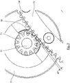
- This auxiliary transmission comprises a pinion 71 mounted to rotate with the output shaft 51 of the motor 5 in the extension of the pulley 61. It also comprises a gear portion 72 integral with the sector 62 and concentric with it. Its teeth protrude at the peripheral surface of the sector. Alternatively, the gear portion may be replaced by a complete gear, especially when the sector will be replaced by a pulley.
- the gear portion 72 is provided to mesh with the gear 71.
- the gear 71 and the gear 72 constitute a gear reducer.
- the reduction ratio of the gearbox to the main transmission is equal to that of the gearbox of the auxiliary transmission.
- the pitch diameter of the pinion 71 is equal to the sum of the diameter of the pulley 61 and the diameter of the cable 63
- the pitch diameter of the gear portion 72 is equal to the sum of the diameter of the sector 62 and the cable diameter 63.
- the spacing between the pinion 71 and the gear portion 72 is slightly increased relative to the distance between the pulley 61 and the sector 62.
- the pitch diameter dp of the pinion 71 is not secant nor tangent to the pitch diameter DP of the gear portion 72. These primitive diameters are instead slightly distant from each other. Thus, in the inactive state, there is a clearance between the teeth of the pinion and the teeth of the toothed wheel.
- the adjustment of this difference in center distance may for example be obtained by mounting the motor on a support that can be moved over a range of adjustment relative to the frame and held in position after adjustment.
- the pinion 71 is not in contact with the wheel portion 72.
- the transmission of torque to the arm 3 is then effected by the main transmission 6 including the capstan reducer and not the auxiliary transmission which is then in an inactive state.
- the cable 63 elongates without breaking until the teeth of the pinion 71 and the gear portion 72 come into contact.
- the mechanical strength of the joint is then provided by the gear system of the auxiliary transmission.
- the torque is then transmitted to the arm by the auxiliary transmission at gear reducer that is in active condition and no longer by the main gearbox transmission.
- the backlash between the teeth of the gear reducer in the idle state and the stiffness of the cable determine the limit force for switching from the gearbox mode to the gearbox mode operation.
- This game will preferably be between 0.1 and 0.5 times the height of the teeth of the gears. It will obviously be determined in such a way that the cable does not break before and during the phases when the auxiliary transmission becomes active.
- the extension of the cable inducing the passage of the auxiliary transmission from its inactive state to its active state will preferably be in the field of elastic deformation.
- the implementation of the auxiliary transmission thus makes it possible to have the transparency and the fluidity of the cable reducer as long as the forces on the arm remain low, and the strong mechanical strength of the gear reducer when the load on the arm becomes stronger.
- the difference dE between the centers is chosen such that when the resisting torque delivered by the motor reaches its maximum value and is no longer sufficient to counteract the forces applied to the arm by its environment, the pinion 71 and the wheel 72 come into contact with each other. This bringing into contact results from the deformation of the main transmission, more particularly of the elongation of the cable, under the effect of the forces applied to the arm by its environment.
- the means for evaluating at least one piece of information representative of a deformation of the main transmission comprise means of detecting whether or not the pinion 71 is in contact with the wheel 72.
- the means for detecting the contact between the pinion and the wheel comprise the pinion and the toothed wheel, made of a conductive material, which constitute an open electrical circuit as long as they are not in contact and closed when they are in touch.
- the deactivation of the braking means is then implemented when, during a braking phase, the pinion and the wheel do not come into contact, which corresponds to the achievement by the information representative of the deformation of the main transmission of the threshold value below which the deactivation means are implemented to deactivate the brake.
- the regulation of the braking is carried out in the following manner with reference to the figure 9 .
- the value of the torque thus evaluated is compared with the maximum value of the resistive torque that can be delivered by the motor.
- the activation means implement a step 91 of activation of the brake during which they control the activation of the brake.
- the brake could be triggered when, during a non-braking phase, the pinion and the wheel come into contact.
- the corresponding technical means can then be implemented for this purpose.
- a step 92 for evaluating the forces transmitted to the arm by its environment is implemented, in this case the torque transmitted by its environment to the arm about its axis of rotation.
- This step consists in measuring at least one piece of information representative of the deformation of the main transmission, which is in this case information representative of the deformation of the cable.
- this step 920 it is detected in a step 921 'the moment at which the pinion and the wheel does not come into contact during braking, that is to say the moment when the circuit they form opens.
- the deactivation means implement a step 93 of deactivating the brake.
- the operation of the arm has been described here by insisting on the phases in which the motor transmits resistant torques to constrain the movement of the arm.
- the motor can also transmit motor torques during phases during which it is desired to accompany the movement of the arm.
- the robotic arm is conventionally programmed for this purpose and controlled by the central unit.
- the forces applied by the motors are calculated by the central unit to prohibit the user to intervene in certain area.
- the device according to the first embodiment may comprise auxiliary transmission.
- the invention applies to a mobility device of a haptic interface.
- such a mobility device of a haptic interface can be implemented for the rehabilitation of the arm of a patient or for comanipulation during a surgical operation.
- a device may be envisaged, without departing from the scope of the invention, to implement such a device to provide a simple haptic interface intended for example for teleoperation applications, video games, reality virtual, computer-aided sports training or technical training.
- it can be expected to integrate a device for moving to a tool changer for which the object to be animated or manipulated is an articulated clamp.
- an operating member such as a manipulator robot, advantageously incorporates a device according to the invention.
- one or more intermediate reducers may be implemented between the output of the motor and the shaft on which is mounted the motor pulley.
- a main transmission or a main transmission / auxiliary transmission torque may be implemented on either side of the articulation connecting the arm to the frame.
- the arm is rotatable relative to the frame along a single axis. In variants, it could be rotatable relative to the frame along several axes.
- the motorized articulated arm will comprise as many assemblies, or pairs of assemblies, motor means, main transmission means, torque evaluation means, braking means, activation means, means evaluation of at least one piece of information representative of a deformation, of means of deactivation, and possibly of auxiliary transmission, of axes around which the arm can rotate, each assembly being dedicated to the transmission of torque according to one of said axes.
- the arm may for example be rotatable relative to the frame along a first axis 2 and along a second axis 2 'orthogonal to the first, a first set, or pairs of sets, motor means 5, main transmission 6 and the if necessary auxiliary transmission 7 being dedicated to the transmission of torque along the first axis 2 and a second set, or pairs of sets, motor means 5 ', main transmission 6' and optionally auxiliary transmission 7 'being dedicate to the transmission of torque along the second axis 2 '.
- motor means 5 ', main transmission 6' and optionally auxiliary transmission 7 ' being dedicate to the transmission of torque along the second axis 2 '.
- the assembly consisting of the arm 3 movable along a first axis 2, the main transmissions 6 and if necessary auxiliary 7 and the motor 5 may be mounted on a plate 8 movable in rotation relative to the frame 2 along another axis 2 '.
- the motorized arm may then include another motor 5 'and another main transmission 6' and optionally another auxiliary transmission 7 'to drive the plate 8 in rotation along the other axis 2' according to the same principle as that according to which the torque of the motor 5 is transmitted to the arm 3 along the first axis 2.
- the arm 3 can of course be rotatable relative to the frame 2 along more than two axes.
Landscapes
- Engineering & Computer Science (AREA)
- Robotics (AREA)
- Mechanical Engineering (AREA)
- Human Computer Interaction (AREA)
- Manipulator (AREA)
Claims (17)
- Motorisierter Gelenkarm mit haptischer Schnittstelle, der wenigstens aufweist:- ein Gestell (1);- einen Arm (3), der drehbewegbar um wenigstens eine Achse (2) mit dem Gestell (1) verbunden ist, wobei Kräfte von seiner Umgebung auf den Arm (3) aufgebracht werden können;- Motormittel (5), die einen Rotor aufweisen und dazu eingerichtet sind, wenigstens ein maximales Widerstandsdrehmoment um die Achse (2) bereitzustellen, das sich wenigstens teilweise gegen die von seiner Umgebung auf den Arm (3) aufgebrachten Kräfte richtet;- ein Hauptgetriebe (6) zum Übertragen des durch die Motormittel (5) erzeugten Widerstandsdrehmoments auf den Arm (3), wobei das Hauptgetriebe (6) eine Winden-Kabeluntersetzung (63) aufweist;- Mittel zum Auswerten des Widerstandsdrehmoments, das durch die Motormittel (5) auf den Arm (3) übertragen werden;- Mittel zum Bremsen (9) der Rotation des Arms (3) um die Achse (2);- Mittel zum Aktivieren (101) der Mittel zum Bremsen (9), wenn das maximale Widerstandsdrehmoment durch die Motormittel (5) erreicht ist;- Mittel zum Auswerten (101, 102, 103), nach dem Aktivieren der Mittel zum Bremsen (9), der von der Umgebung auf den Arm (3) übertragenen Kräfte, wobei die Mittel zum Auswerten Mittel zum Bestimmen wenigstens einer Information aufweisen, die für eine Deformation des Getriebes (6) unter der Wirkung der Kräfte repräsentativ ist;- Mittel zum Deaktivieren (101) der Mittel zum Bremsen (9), wenn die Information, die für eine Deformation des Getriebes (6) repräsentativ ist, kleiner als ein vordefinierter Schwellwert wird.
- Arm nach Anspruch 1, in welchem die Mittel zum Auswerten (101, 102, 103) wenigstens einer Information, die für eine Deformation des Getriebes repräsentativ ist, Mittel zum Auswerten der Deformation des Kabels (63) aufweisen.
- Arm nach Anspruch 1 oder 2, in welchem die Mittel zum Auswerten wenigstens einer Information, die für eine Deformation des Getriebes unter der Wirkung der von seiner Umgebung auf den Arm (3) übertragenen Kräfte repräsentativ ist, nach dem Aktivieren der Mittel zum Bremsen (9) aufweisen:- Mittel zum Bestimmen (102) der Winkelposition des Rotors um seine Rotationsachse;- Mittel zum Schätzen (102, 101) der theoretischen Winkelposition des Arms (3) um seine Rotationsachse bezüglich des Gestells (1) ausgehend von der Winkelposition des Rotors;- Mittel zum Bestimmen (101, 103) der realen Winkelposition des Arms (3) um seine Rotationsachse bezüglich des Gestells (1);- Mittel zum Bestimmen (101) des Unterschieds zwischen dem theoretischen Wert und dem realen Wert der Winkelposition des Arms (3) um seine Rotationsachse;wobei die Mittel zum Deaktivieren (101) eingerichtet sind, die Mittel zum Bremsen (9) zu deaktivieren, wenn der Unterschied kleiner als der vordefinierte Schwellwert wird.
- Arm nach Anspruch 3, in welchem die Mittel zum Bestimmen (101, 103) der realen Winkelposition des Arms (3) um seine Rotationsachse bezüglich des Gestells (1) einen Winkelpositionssensor (103) des Arms um seine Rotationsachse aufweisen.
- Arm nach einem der Ansprüche 1 bis 4, in welchem das Hauptgetriebe (6) aufweist:- ein Antriebselement (62), das drehbar mit dem Arm (3) verbunden ist, wobei das Antriebselement wenigstens einen Winkelsektor aufweist, dessen Achse mit der Rotationsachse (2) des Arms (3) koinzidiert;- eine Antriebsscheibe (61), die mit den Motormitteln (5) verbunden ist;wobei sich das Kabel (63) der Kabeluntersetzung entlang des Winkelsektors (62) gerollt um die Scheibe (61) erstreckt, wobei die Enden des Kabels (63) an dem Antriebselement (62) fixiert sind.
- Arm nach einem der Ansprüche 1 bis 5, der ein Hilfsgetriebe (7) zum Übertragen des Widerstandsdrehmoments auf den Arm (3) aufweist, wobei das Hilfsgetriebe wenigstens zwei Zustände einnehmen kann:- einen inaktiven Zustand, der solange eingenommen wird, wie die von seiner Umgebung auf den Arm (3) aufgebrachten Kräfte gegen die Wirkung des Drehmoments niedriger als ein vordefinierter Schwellwert sind, in welchem das Hilfsgetriebe (7) kein Drehmoment auf den Arm (3) überträgt;- einen aktiven Zustand, der dann eingenommen wird, wenn die von seiner Umgebung auf den Arm (3) aufgebrachten Kräfte gegen die Wirkung des Drehmoments größer als ein vordefinierter Schwellwert sind, in welchem das Hauptgetriebe (6) kein Drehmoment auf den Arm (3) überträgt.
- Gelenkarm nach Anspruch 6, in welchem das Hilfsgetriebe (7) konfiguriert ist, den aktiven Zustand dann einzunehmen, wenn die von der Umgebung auf den Arm (3) gegen die Wirkung des Widerstandsdrehmoments aufgebrachten Kräfte eine Deformation des Kabels induzieren, die einen vorbestimmten Schwellwert übersteigt.
- Gelenkarm nach Anspruch 7, in welchem das Hilfsgetriebe (7) aufweist:- ein Ritzel (71), das mit den Motormitteln verbunden ist und in der Achse der Scheibe (61) montiert ist,- wenigstens einen Teil eines Zahnrades (72), der mit dem Antriebselement (62) verbunden ist und in das Ritzel (71) eingreift;wobei das Untersetzungsverhältnis des Hilfsgetriebes (7) identisch mit dem des Hauptgetriebes (6) ist,
wobei der Achsabstand zwischen der Rotationsachse des Ritzels (71) und der Rotationsachse des Zahnrades (72) größer als der Achsabstand zwischen der Rotationsachse der Scheibe (61) und der Rotationsachse des Antriebselementes (62) derart ist, dass das Ritzel (71) und das Rad (72) nur dann in Kontakt sind und ineinander eingreifen, wenn sich das Hilfsgetriebe (7) in dem aktiven Zustand befindet. - Arm nach Anspruch 8, in welchem die Mittel zum Auswerten wenigstens einer Information, die für eine Deformation des Getriebes repräsentativ ist, Mittel zur Detektion (101) des Eintritts oder nicht des Kontaktes des Ritzels (71) mit dem Rad (72) aufweisen, wobei der Schwellwert der Information, der für die Deformation repräsentativ ist, der die Deaktivierung der Mittel zum Bremsen (9) auslöst, dann erreicht ist, wenn das Ritzel (71) und das Rad (72) nicht mehr in Kontakt stehen während die Mittel zum Aktivieren (101) die Mittel zum Bremsen (9) aktivieren.
- Arm nach Anspruch 9, in welchem die Mittel zum Detektieren (101) des Eintritts des Ritzels (71) in Kontakt mit dem Rad (72) das Ritzel und das Zahnrad aufweisen, die einen elektrischen Stromkreis bilden, der solange geöffnet ist, solange sie nicht in Kontakt sind, und der geschlossen ist, wenn sie in Kontakt sind.
- Gelenkarm nach einem der Ansprüche 8 bis 10, in welchem der Unterschied zwischen den Achsabständen innerhalb eines Bereiches von 0,1 bis 0,5 mal der Höhe der Zähne des Ritzels (71) und des Zahnrades (72) enthalten ist.
- Arm nach einem der Ansprüche 8 bis 11, in welchem der Unterschied dE zwischen den Achsabständen gemäß der folgenden Formel bestimmt wird:
 mit alpha: Winkel des Druckes der VerzahnungK: Steifigkeit des KabelsF: SicherheitsfaktorCmax: maximale Last auf dem Kabel
 - Gelenkarm nach einem der Ansprüche 1 bis 12, in welchem der Arm (3) drehbewegbar bezüglich des Gestells (1) gemäß einer Vielzahl von Achsen montiert ist, wobei der Gelenkarm ebenso viele Sätze von Motormitteln, von Hauptgetrieben, Mitteln zum Auswerten des Drehmoments, von Mitteln zum Bremsen, von Mitteln zum Aktivieren, von Mitteln zum Auswerten wenigstens einer Information, die für eine Deformation repräsentativ ist, von Mitteln zum Deaktivieren und gegebenenfalls von Hilfsgetrieben, wie es Achsen gibt, um die sich der Arm (3) drehen kann, aufweist, wobei jeder Satz der Übertragung des Drehmoments gemäß einer der Achsen gewidmet ist.
- Anwendung des Arms nach einem der Ansprüche 1 bis 13 in einem technischen Gebiet, das zur Gruppe gehört, umfassend:- haptische Schnittstelle mit einer virtuellen Umgebung;- haptische Schnittstelle mit einer Umgebung der erweiterten Realität;- therapeutische Rehabilitation;- computergestütztes Design;- Telebetrieb;- Sporttraining;- Trainieren technischer Gesten.
- Verfahren zum Steuern eines motorisierten Gelenkarmes mit haptischer Schnittstelle, der wenigstens aufweist:- ein Gestell (1);- einen Arm (3), der mit dem Gestell (1) drehbewegbar um wenigstens eine Achse (2) verbunden ist, wobei die Kräfte von seiner Umgebung auf den Arm (3) aufgebracht werden können;- Motormittel (5), die einen Rotor aufweisen und die dazu eingerichtet sind, wenigstens ein maximales Widerstandsdrehmoment um die Achse (2) zu liefern, das wenigstens teilweise den Kräften, die von seiner Umgebung auf den Arm (3) aufgebracht werden, entgegen wirkt;- ein Hauptgetriebe (6) zum Übertragen des Widerstandsdrehmoments, das durch die Motormittel (5) erzeugt wird, auf den Arm (3), wobei das Hauptgetriebe (6) eine Winden-Kabeluntersetzung (63) aufweist;- Mittel zum Bremsen (9) der Rotation des Arms (3) um die Achse (2);wobei das Verfahren aufweist:- einen Schritt des Auswertens des Widerstandsdrehmoments, das durch die Motormittel (5) auf den Arm (3) übertragen wird;- einen Schritt des Aktivierens der Mittel zum Bremsen (9), wenn das maximale Widerstandsdrehmoment durch die Motormittel (5) erreicht ist;- einen Schritt des Auswertens, nach dem Aktivieren der Mittel zum Bremsen (9), der von der Umgebung auf den Arm (3) übertragenen Kräfte, aufweisend einen Schritt des Bestimmens wenigstens einer Information, die für eine Deformation des Hauptgetriebes (6) unter der Wirkung der Kräfte repräsentativ ist;- einen Schritt des Deaktivierens der Mittel zum Bremsen (9), wenn die Information, die für eine Deformation des Hauptgetriebes (6) repräsentativ ist, niedriger als ein vorbestimmter Schwellwert wird.
- Verfahren zum Steuern eines motorisierten Gelenkarmes nach Anspruch 15, in welchem der Schritt des Auswertens wenigstens einer Information, die für eine Deformation des Getriebes (6) unter der Wirkung der von seiner Umgebung auf den Arm (3) übertragenen Kräfte repräsentativ ist, nach dem Aktivieren der Mittel zum Bremsen (9) aufweist:- einen Schritt des Bestimmens der Winkelposition des Rotors um seine Rotationsachse;- einen Schritt des Schätzens der theoretischen Winkelposition des Arms (3) um seine Rotationsachse bezüglich des Gestells ausgehend von der Winkelposition des Rotors;- einen Schritt des Bestimmens der realen Winkelposition des Arms (3) um seine Rotationsachse bezüglich des Gestells (1);- einen Schritt des Bestimmens des Unterschiedes zwischen dem theoretischen Wert und dem realen Wert der Winkelposition des Arms (3) um seine Rotationsachse (2);- wobei der Schritt des Deaktivierens dann aufgeführt wird, wenn der Unterscheid niedriger als der vorbestimmte Schwellwert wird.
- Verfahren zum Steuern eines motorisierten Gelenkarmes nach Anspruch 15 oder 16, wobei der motorisierte Gelenkarm ein Hilfsgetriebe (7) zum Übertragen des Widerstandsdrehmomentes auf den Arm (3) aufweist, wobei das Hilfsgetriebe (7) wenigstens zwei Zustände einnehmen kann:- einen inaktiven Zustand, der solange eingenommen wird, wie die von seiner Umgebung auf den Arm (3) aufgebrachten Kräfte gegen die Wirkung des Drehmoments geringer als ein Schwellwert sind, in welchem das Hilfsgetriebe (7) kein Drehmoment auf den Arm (3) überträgt;- einen aktiven Zustand, der dann eingenommen wird, wenn die von seiner Umgebung auf den Arm (3) aufgebrachten Kräfte gegen die Wirkung des Drehmoments größer als ein vorbestimmter Schwellwert sind, in welchem das Hauptgetriebe (6) kein Drehmoment auf den Arm (3) überträgt,wobei das Hilfsgetriebe (7) aufweist:- ein Ritzel (71), das mit den Motormitteln (5) verbunden ist und in der Achse der Scheibe (61) montiert ist;- wenigstens einen Teil eines Zahnrades (72), der mit dem Antriebselement (62) verbunden ist und in das Ritzel (71) eingreift;wobei das Untersetzungsverhältnis des Hilfsgetriebes (77) identisch mit dem des Hauptgetriebes (6) ist,
wobei der Achsabstand zwischen der Rotationsachse des Ritzels (71) und der Rotationsachse des Zahnrades (72) größer als der Achsabstand zwischen der Rotationsachse der Scheibe (61) und der Rotationsachse des Antriebselementes (62) ist, derart, dass das Ritzel (71) und das Rad (72) nur dann in Kontakt sind und ineinander eingreifen, wenn sich das Hilfsgetriebe (7) in dem aktiven Zustand befindet;
wobei der Schritt des Auswertens wenigstens einer Information, die für die Deformation des Getriebes (6) repräsentativ ist, einen Schritt des Erkennens, ob das Ritzel (71) mit dem Rad (72) in Kontakt gekommen ist oder nicht, aufweist, wobei der Schwellwert der Information, die für Deformation repräsentativ ist, der die Deaktivierung der Mittel zum Bremsen (9) auslöst, dann erreicht wird, wenn das Ritzel (71) und das Rad (725) nicht länger in Kontakt kommen während die Mittel zum Bremsen (9) aktiviert sind.
Applications Claiming Priority (1)
| Application Number | Priority Date | Filing Date | Title |
|---|---|---|---|
| FR1556001A FR3037840B1 (fr) | 2015-06-26 | 2015-06-26 | Bras articule motorise a cabestan a cable comprenant un frein. |
Publications (2)
| Publication Number | Publication Date |
|---|---|
| EP3109014A1 EP3109014A1 (de) | 2016-12-28 |
| EP3109014B1 true EP3109014B1 (de) | 2017-09-20 |
Family
ID=54186122
Family Applications (1)
| Application Number | Title | Priority Date | Filing Date |
|---|---|---|---|
| EP16175633.3A Active EP3109014B1 (de) | 2015-06-26 | 2016-06-22 | Motorisierter gelenkarm mit capstan mit kabel, der eine bremse umfasst |
Country Status (3)
| Country | Link |
|---|---|
| US (1) | US10118289B2 (de) |
| EP (1) | EP3109014B1 (de) |
| FR (1) | FR3037840B1 (de) |
Cited By (1)
| Publication number | Priority date | Publication date | Assignee | Title |
|---|---|---|---|---|
| DE102019128082A1 (de) * | 2019-10-17 | 2021-04-22 | Franka Emika Gmbh | Drehmomentbegrenztes Bremsen eines Robotermanipulators |
Families Citing this family (22)
| Publication number | Priority date | Publication date | Assignee | Title |
|---|---|---|---|---|
| DE102013223603A1 (de) * | 2013-11-19 | 2015-05-21 | Ferrobotics Compliant Robot Technology Gmbh | Roboterarm |
| TWD176622S (zh) * | 2015-09-24 | 2016-06-21 | 上銀科技股份有限公司 | 移動載具之部分 |
| JP2020532405A (ja) * | 2017-09-05 | 2020-11-12 | コヴィディエン リミテッド パートナーシップ | デュアルエンコーダを含むロボット手術システムの制御アーム |
| CN110547093B (zh) * | 2019-08-28 | 2024-09-03 | 贵州航天智慧农业有限公司 | 一种轻量化农业采摘机械臂 |
| US12042241B2 (en) | 2021-03-31 | 2024-07-23 | Moon Surgical Sas | Co-manipulation surgical system having automated preset robot arm configurations |
| WO2024075047A2 (en) | 2022-10-05 | 2024-04-11 | Moon Surgical Sas | Co-manipulation surgical system having a coupling mechanism removeably attachable to surgical instruments |
| US11819302B2 (en) | 2021-03-31 | 2023-11-21 | Moon Surgical Sas | Co-manipulation surgical system having user guided stage control |
| US11844583B2 (en) | 2021-03-31 | 2023-12-19 | Moon Surgical Sas | Co-manipulation surgical system having an instrument centering mode for automatic scope movements |
| US12167900B2 (en) | 2021-03-31 | 2024-12-17 | Moon Surgical Sas | Co-manipulation surgical system having automated preset robot arm configurations |
| US11832909B2 (en) | 2021-03-31 | 2023-12-05 | Moon Surgical Sas | Co-manipulation surgical system having actuatable setup joints |
| EP4312857B1 (de) | 2021-03-31 | 2025-09-03 | Moon Surgical SAS | Chirurgisches system mit co-manipulation zur verwendung mit chirurgischen instrumenten zur durchführung laparoskopischer chirurgie |
| US11812938B2 (en) | 2021-03-31 | 2023-11-14 | Moon Surgical Sas | Co-manipulation surgical system having a coupling mechanism removeably attachable to surgical instruments |
| US12178418B2 (en) | 2021-03-31 | 2024-12-31 | Moon Surgical Sas | Co-manipulation surgical system having a coupling mechanism removeably attachable to surgical instruments |
| JP7712117B2 (ja) * | 2021-06-08 | 2025-07-23 | 川崎重工業株式会社 | 手術支援システム、操作者側装置および手術支援システムの制御方法 |
| CN117615732A (zh) | 2021-07-05 | 2024-02-27 | 月球外科公司 | 与用于执行腹腔镜外科手术的外科手术器械一起使用的具有光学扫描仪的共同操纵外科手术系统 |
| US20250186142A1 (en) | 2022-04-19 | 2025-06-12 | Moon Surgical Sas | Intelligent robotic comanipulation assistant for surgery |
| AU2024208004A1 (en) | 2023-01-09 | 2025-07-03 | Moon Surgical Sas | Co-manipulation surgical system having automated preset robot arm configurations |
| US12370001B2 (en) | 2023-01-09 | 2025-07-29 | Moon Surgical Sas | Co-manipulation surgical system having automated user override detection |
| US11986165B1 (en) | 2023-01-09 | 2024-05-21 | Moon Surgical Sas | Co-manipulation surgical system for use with surgical instruments for performing laparoscopic surgery while estimating hold force |
| US11832910B1 (en) | 2023-01-09 | 2023-12-05 | Moon Surgical Sas | Co-manipulation surgical system having adaptive gravity compensation |
| WO2026033353A1 (en) | 2024-08-05 | 2026-02-12 | Moon Surgical Sas | Coupling mechanism for removeably attaching surgical instruments to a co-manipulation surgical system |
| WO2026038170A1 (en) | 2024-08-14 | 2026-02-19 | Moon Surgical Sas | Co-manipulation surgical system with backend processing for data handling and analytics |
Family Cites Families (6)
| Publication number | Priority date | Publication date | Assignee | Title |
|---|---|---|---|---|
| US5207114A (en) * | 1988-04-21 | 1993-05-04 | Massachusetts Institute Of Technology | Compact cable transmission with cable differential |
| US5046375A (en) | 1988-04-21 | 1991-09-10 | Massachusetts Institute Of Technology | Compact cable transmission with cable differential |
| US9037295B2 (en) * | 2008-03-07 | 2015-05-19 | Perception Raisonnement Action En Medecine | Dynamic physical constraint for hard surface emulation |
| FR2950831B1 (fr) * | 2009-10-05 | 2012-08-10 | Commissariat Energie Atomique | Articulation motorisee pour bras de robot |
| FR2961423B1 (fr) * | 2010-06-17 | 2012-07-27 | Commissariat Energie Atomique | Reducteur a grand rapport de reduction, robot et interface haptique comportant au moins un tel reducteur |
| KR20140052987A (ko) * | 2011-03-30 | 2014-05-07 | 스큐즈 가부시키가이샤 | 스콧 러셀 기구식 장치 |
-
2015
- 2015-06-26 FR FR1556001A patent/FR3037840B1/fr not_active Expired - Fee Related
-
2016
- 2016-06-22 EP EP16175633.3A patent/EP3109014B1/de active Active
- 2016-06-27 US US15/193,948 patent/US10118289B2/en active Active
Non-Patent Citations (1)
| Title |
|---|
| None * |
Cited By (2)
| Publication number | Priority date | Publication date | Assignee | Title |
|---|---|---|---|---|
| DE102019128082A1 (de) * | 2019-10-17 | 2021-04-22 | Franka Emika Gmbh | Drehmomentbegrenztes Bremsen eines Robotermanipulators |
| DE102019128082B4 (de) | 2019-10-17 | 2022-03-10 | Franka Emika Gmbh | Drehmomentbegrenztes Bremsen eines Robotermanipulators |
Also Published As
| Publication number | Publication date |
|---|---|
| EP3109014A1 (de) | 2016-12-28 |
| FR3037840B1 (fr) | 2017-08-18 |
| FR3037840A1 (fr) | 2016-12-30 |
| US20160375577A1 (en) | 2016-12-29 |
| US10118289B2 (en) | 2018-11-06 |
Similar Documents
| Publication | Publication Date | Title |
|---|---|---|
| EP3109014B1 (de) | Motorisierter gelenkarm mit capstan mit kabel, der eine bremse umfasst | |
| EP3109011B1 (de) | Motorisierter gelenkarm mit sichere capstan mit kabel | |
| EP2485876B1 (de) | Motorgetriebenes selbstsperrendes gelenk für einen roboterarm | |
| WO2011039341A1 (fr) | Structure de robot ou d'interface haptique a bras en parallele | |
| FR2935175A1 (fr) | Dispositif permettant de determiner la position relative entre deux organes dont l'un au moins est mobile, et machines et appareils en faisant application | |
| FR3016512A1 (fr) | Dispositif d'interface maitre pour systeme endoscopique motorise et installation comprenant un tel dispositif | |
| CA2087348C (fr) | Dispositif de support et de positionnement d'un microscope | |
| FR3004680A1 (fr) | Dispositif de commande de la vitesse d'un engin a propulsion electrique et engin correspondant | |
| EP4142632B1 (de) | Steuerschnittstelle und robotersystem mit solch einer steuerschnittstelle | |
| EP3148753A1 (de) | Cobotischer manipulator | |
| CA2552589A1 (fr) | Dispositif de trocart pour le passage d'un instrument chirurgical | |
| EP2054200B1 (de) | Werkzeug mit hilfsvorrichtung zur betätigung | |
| FR3055235B1 (fr) | Dispositif de vissage a mesure de couple de sortie optimisee, et procede de determination du couple de sortie correspondant | |
| WO2020136357A1 (fr) | Dispositif d'application d'effort pour un manche de pilotage d'un aéronef | |
| WO2007122242A1 (fr) | Organe de commande a cables tendus | |
| FR3117912A1 (fr) | Robot de co-manipulation à loi de commande en effort mixte offrant une forte sensibilité de l’effecteur et permettant l’interaction avec le corps du robot. | |
| FR3142174A1 (fr) | Compensateur de vol actif et hybride pour aéronef | |
| JP2009061541A (ja) | 過負荷検出機構及びそれを備えた産業用ロボット | |
| FR2950830A1 (fr) | Structure de robot ou d'interface haptique a bras en paralleles | |
| WO2010112731A2 (fr) | Interface homme-machine | |
| FR3026501A1 (fr) | Procede et interface de commande a retour haptique pour vehicule automobile | |
| EP3107696A1 (de) | Roboterarmgelenk, insbesondere für haptische und/oder cobotic-verwendungen | |
| FR3142173A1 (fr) | Système de commande de vol pour un compensateur de vol à friction, actif et hybride d’un aéronef | |
| CA3236996A1 (fr) | Doigt et dispositif de prehension pour bras de robot, bras de robot equipe d'un tel dispositif | |
| FR3044115A1 (fr) | Procede de programmation d’un effort a exercer par un robot |
Legal Events
| Date | Code | Title | Description |
|---|---|---|---|
| PUAI | Public reference made under article 153(3) epc to a published international application that has entered the european phase |
Free format text: ORIGINAL CODE: 0009012 |
|
| AK | Designated contracting states |
Kind code of ref document: A1 Designated state(s): AL AT BE BG CH CY CZ DE DK EE ES FI FR GB GR HR HU IE IS IT LI LT LU LV MC MK MT NL NO PL PT RO RS SE SI SK SM TR |
|
| AX | Request for extension of the european patent |
Extension state: BA ME |
|
| GRAP | Despatch of communication of intention to grant a patent |
Free format text: ORIGINAL CODE: EPIDOSNIGR1 |
|
| 17P | Request for examination filed |
Effective date: 20170222 |
|
| RBV | Designated contracting states (corrected) |
Designated state(s): AL AT BE BG CH CY CZ DE DK EE ES FI FR GB GR HR HU IE IS IT LI LT LU LV MC MK MT NL NO PL PT RO RS SE SI SK SM TR |
|
| RIC1 | Information provided on ipc code assigned before grant |
Ipc: B25J 19/00 20060101ALI20170316BHEP Ipc: B25J 13/02 20060101AFI20170316BHEP |
|
| INTG | Intention to grant announced |
Effective date: 20170330 |
|
| GRAS | Grant fee paid |
Free format text: ORIGINAL CODE: EPIDOSNIGR3 |
|
| GRAA | (expected) grant |
Free format text: ORIGINAL CODE: 0009210 |
|
| AK | Designated contracting states |
Kind code of ref document: B1 Designated state(s): AL AT BE BG CH CY CZ DE DK EE ES FI FR GB GR HR HU IE IS IT LI LT LU LV MC MK MT NL NO PL PT RO RS SE SI SK SM TR |
|
| REG | Reference to a national code |
Ref country code: GB Ref legal event code: FG4D Free format text: NOT ENGLISH |
|
| REG | Reference to a national code |
Ref country code: CH Ref legal event code: EP |
|
| REG | Reference to a national code |
Ref country code: AT Ref legal event code: REF Ref document number: 929791 Country of ref document: AT Kind code of ref document: T Effective date: 20171015 |
|
| REG | Reference to a national code |
Ref country code: IE Ref legal event code: FG4D Free format text: LANGUAGE OF EP DOCUMENT: FRENCH |
|
| REG | Reference to a national code |
Ref country code: DE Ref legal event code: R096 Ref document number: 602016000424 Country of ref document: DE |
|
| REG | Reference to a national code |
Ref country code: NL Ref legal event code: MP Effective date: 20170920 |
|
| PG25 | Lapsed in a contracting state [announced via postgrant information from national office to epo] |
Ref country code: HR Free format text: LAPSE BECAUSE OF FAILURE TO SUBMIT A TRANSLATION OF THE DESCRIPTION OR TO PAY THE FEE WITHIN THE PRESCRIBED TIME-LIMIT Effective date: 20170920 Ref country code: NO Free format text: LAPSE BECAUSE OF FAILURE TO SUBMIT A TRANSLATION OF THE DESCRIPTION OR TO PAY THE FEE WITHIN THE PRESCRIBED TIME-LIMIT Effective date: 20171220 Ref country code: LT Free format text: LAPSE BECAUSE OF FAILURE TO SUBMIT A TRANSLATION OF THE DESCRIPTION OR TO PAY THE FEE WITHIN THE PRESCRIBED TIME-LIMIT Effective date: 20170920 Ref country code: FI Free format text: LAPSE BECAUSE OF FAILURE TO SUBMIT A TRANSLATION OF THE DESCRIPTION OR TO PAY THE FEE WITHIN THE PRESCRIBED TIME-LIMIT Effective date: 20170920 Ref country code: SE Free format text: LAPSE BECAUSE OF FAILURE TO SUBMIT A TRANSLATION OF THE DESCRIPTION OR TO PAY THE FEE WITHIN THE PRESCRIBED TIME-LIMIT Effective date: 20170920 |
|
| REG | Reference to a national code |
Ref country code: LT Ref legal event code: MG4D |
|
| REG | Reference to a national code |
Ref country code: AT Ref legal event code: MK05 Ref document number: 929791 Country of ref document: AT Kind code of ref document: T Effective date: 20170920 |
|
| PG25 | Lapsed in a contracting state [announced via postgrant information from national office to epo] |
Ref country code: LV Free format text: LAPSE BECAUSE OF FAILURE TO SUBMIT A TRANSLATION OF THE DESCRIPTION OR TO PAY THE FEE WITHIN THE PRESCRIBED TIME-LIMIT Effective date: 20170920 Ref country code: GR Free format text: LAPSE BECAUSE OF FAILURE TO SUBMIT A TRANSLATION OF THE DESCRIPTION OR TO PAY THE FEE WITHIN THE PRESCRIBED TIME-LIMIT Effective date: 20171221 Ref country code: BG Free format text: LAPSE BECAUSE OF FAILURE TO SUBMIT A TRANSLATION OF THE DESCRIPTION OR TO PAY THE FEE WITHIN THE PRESCRIBED TIME-LIMIT Effective date: 20171220 Ref country code: RS Free format text: LAPSE BECAUSE OF FAILURE TO SUBMIT A TRANSLATION OF THE DESCRIPTION OR TO PAY THE FEE WITHIN THE PRESCRIBED TIME-LIMIT Effective date: 20170920 |
|
| PG25 | Lapsed in a contracting state [announced via postgrant information from national office to epo] |
Ref country code: NL Free format text: LAPSE BECAUSE OF FAILURE TO SUBMIT A TRANSLATION OF THE DESCRIPTION OR TO PAY THE FEE WITHIN THE PRESCRIBED TIME-LIMIT Effective date: 20170920 |
|
| PG25 | Lapsed in a contracting state [announced via postgrant information from national office to epo] |
Ref country code: RO Free format text: LAPSE BECAUSE OF FAILURE TO SUBMIT A TRANSLATION OF THE DESCRIPTION OR TO PAY THE FEE WITHIN THE PRESCRIBED TIME-LIMIT Effective date: 20170920 Ref country code: CZ Free format text: LAPSE BECAUSE OF FAILURE TO SUBMIT A TRANSLATION OF THE DESCRIPTION OR TO PAY THE FEE WITHIN THE PRESCRIBED TIME-LIMIT Effective date: 20170920 Ref country code: PL Free format text: LAPSE BECAUSE OF FAILURE TO SUBMIT A TRANSLATION OF THE DESCRIPTION OR TO PAY THE FEE WITHIN THE PRESCRIBED TIME-LIMIT Effective date: 20170920 Ref country code: ES Free format text: LAPSE BECAUSE OF FAILURE TO SUBMIT A TRANSLATION OF THE DESCRIPTION OR TO PAY THE FEE WITHIN THE PRESCRIBED TIME-LIMIT Effective date: 20170920 |
|
| PG25 | Lapsed in a contracting state [announced via postgrant information from national office to epo] |
Ref country code: IS Free format text: LAPSE BECAUSE OF FAILURE TO SUBMIT A TRANSLATION OF THE DESCRIPTION OR TO PAY THE FEE WITHIN THE PRESCRIBED TIME-LIMIT Effective date: 20180120 Ref country code: EE Free format text: LAPSE BECAUSE OF FAILURE TO SUBMIT A TRANSLATION OF THE DESCRIPTION OR TO PAY THE FEE WITHIN THE PRESCRIBED TIME-LIMIT Effective date: 20170920 Ref country code: SM Free format text: LAPSE BECAUSE OF FAILURE TO SUBMIT A TRANSLATION OF THE DESCRIPTION OR TO PAY THE FEE WITHIN THE PRESCRIBED TIME-LIMIT Effective date: 20170920 Ref country code: IT Free format text: LAPSE BECAUSE OF FAILURE TO SUBMIT A TRANSLATION OF THE DESCRIPTION OR TO PAY THE FEE WITHIN THE PRESCRIBED TIME-LIMIT Effective date: 20170920 Ref country code: AT Free format text: LAPSE BECAUSE OF FAILURE TO SUBMIT A TRANSLATION OF THE DESCRIPTION OR TO PAY THE FEE WITHIN THE PRESCRIBED TIME-LIMIT Effective date: 20170920 Ref country code: SK Free format text: LAPSE BECAUSE OF FAILURE TO SUBMIT A TRANSLATION OF THE DESCRIPTION OR TO PAY THE FEE WITHIN THE PRESCRIBED TIME-LIMIT Effective date: 20170920 |
|
| REG | Reference to a national code |
Ref country code: DE Ref legal event code: R097 Ref document number: 602016000424 Country of ref document: DE |
|
| REG | Reference to a national code |
Ref country code: FR Ref legal event code: PLFP Year of fee payment: 3 |
|
| PLBE | No opposition filed within time limit |
Free format text: ORIGINAL CODE: 0009261 |
|
| STAA | Information on the status of an ep patent application or granted ep patent |
Free format text: STATUS: NO OPPOSITION FILED WITHIN TIME LIMIT |
|
| PG25 | Lapsed in a contracting state [announced via postgrant information from national office to epo] |
Ref country code: DK Free format text: LAPSE BECAUSE OF FAILURE TO SUBMIT A TRANSLATION OF THE DESCRIPTION OR TO PAY THE FEE WITHIN THE PRESCRIBED TIME-LIMIT Effective date: 20170920 |
|
| 26N | No opposition filed |
Effective date: 20180621 |
|
| PG25 | Lapsed in a contracting state [announced via postgrant information from national office to epo] |
Ref country code: MT Free format text: LAPSE BECAUSE OF FAILURE TO SUBMIT A TRANSLATION OF THE DESCRIPTION OR TO PAY THE FEE WITHIN THE PRESCRIBED TIME-LIMIT Effective date: 20170920 |
|
| REG | Reference to a national code |
Ref country code: BE Ref legal event code: MM Effective date: 20180630 |
|
| REG | Reference to a national code |
Ref country code: IE Ref legal event code: MM4A |
|
| PG25 | Lapsed in a contracting state [announced via postgrant information from national office to epo] |
Ref country code: LU Free format text: LAPSE BECAUSE OF NON-PAYMENT OF DUE FEES Effective date: 20180622 Ref country code: MC Free format text: LAPSE BECAUSE OF FAILURE TO SUBMIT A TRANSLATION OF THE DESCRIPTION OR TO PAY THE FEE WITHIN THE PRESCRIBED TIME-LIMIT Effective date: 20170920 |
|
| PG25 | Lapsed in a contracting state [announced via postgrant information from national office to epo] |
Ref country code: IE Free format text: LAPSE BECAUSE OF NON-PAYMENT OF DUE FEES Effective date: 20180622 |
|
| PG25 | Lapsed in a contracting state [announced via postgrant information from national office to epo] |
Ref country code: BE Free format text: LAPSE BECAUSE OF NON-PAYMENT OF DUE FEES Effective date: 20180630 |
|
| REG | Reference to a national code |
Ref country code: CH Ref legal event code: PL |
|
| PG25 | Lapsed in a contracting state [announced via postgrant information from national office to epo] |
Ref country code: TR Free format text: LAPSE BECAUSE OF FAILURE TO SUBMIT A TRANSLATION OF THE DESCRIPTION OR TO PAY THE FEE WITHIN THE PRESCRIBED TIME-LIMIT Effective date: 20170920 |
|
| PG25 | Lapsed in a contracting state [announced via postgrant information from national office to epo] |
Ref country code: CH Free format text: LAPSE BECAUSE OF NON-PAYMENT OF DUE FEES Effective date: 20190630 Ref country code: LI Free format text: LAPSE BECAUSE OF NON-PAYMENT OF DUE FEES Effective date: 20190630 Ref country code: PT Free format text: LAPSE BECAUSE OF FAILURE TO SUBMIT A TRANSLATION OF THE DESCRIPTION OR TO PAY THE FEE WITHIN THE PRESCRIBED TIME-LIMIT Effective date: 20170920 |
|
| PG25 | Lapsed in a contracting state [announced via postgrant information from national office to epo] |
Ref country code: CY Free format text: LAPSE BECAUSE OF FAILURE TO SUBMIT A TRANSLATION OF THE DESCRIPTION OR TO PAY THE FEE WITHIN THE PRESCRIBED TIME-LIMIT Effective date: 20170920 Ref country code: MK Free format text: LAPSE BECAUSE OF NON-PAYMENT OF DUE FEES Effective date: 20170920 Ref country code: HU Free format text: LAPSE BECAUSE OF FAILURE TO SUBMIT A TRANSLATION OF THE DESCRIPTION OR TO PAY THE FEE WITHIN THE PRESCRIBED TIME-LIMIT; INVALID AB INITIO Effective date: 20160622 |
|
| PG25 | Lapsed in a contracting state [announced via postgrant information from national office to epo] |
Ref country code: AL Free format text: LAPSE BECAUSE OF FAILURE TO SUBMIT A TRANSLATION OF THE DESCRIPTION OR TO PAY THE FEE WITHIN THE PRESCRIBED TIME-LIMIT Effective date: 20170920 |
|
| PG25 | Lapsed in a contracting state [announced via postgrant information from national office to epo] |
Ref country code: SI Free format text: LAPSE BECAUSE OF NON-PAYMENT OF DUE FEES Effective date: 20180622 |
|
| P01 | Opt-out of the competence of the unified patent court (upc) registered |
Effective date: 20230530 |
|
| REG | Reference to a national code |
Ref country code: DE Ref legal event code: R082 Ref document number: 602016000424 Country of ref document: DE Representative=s name: VOSSIUS & PARTNER PATENTANWAELTE RECHTSANWAELT, DE Ref country code: DE Ref legal event code: R081 Ref document number: 602016000424 Country of ref document: DE Owner name: MOON SURGICAL SAS, FR Free format text: FORMER OWNER: HAPTION, SOULGE-SUR-OUETTE, FR |
|
| REG | Reference to a national code |
Ref country code: GB Ref legal event code: 732E Free format text: REGISTERED BETWEEN 20231019 AND 20231025 |
|
| REG | Reference to a national code |
Ref country code: DE Ref legal event code: R088 Ref document number: 602016000424 Country of ref document: DE |
|
| REG | Reference to a national code |
Ref country code: GB Ref legal event code: 732E Free format text: REGISTERED BETWEEN 20240620 AND 20240627 |
|
| PGFP | Annual fee paid to national office [announced via postgrant information from national office to epo] |
Ref country code: GB Payment date: 20250626 Year of fee payment: 10 |
|
| PGFP | Annual fee paid to national office [announced via postgrant information from national office to epo] |
Ref country code: FR Payment date: 20250623 Year of fee payment: 10 |
|
| PGFP | Annual fee paid to national office [announced via postgrant information from national office to epo] |
Ref country code: DE Payment date: 20250717 Year of fee payment: 10 |