EP3109075B1 - Bedienerstation - Google Patents
Bedienerstation Download PDFInfo
- Publication number
- EP3109075B1 EP3109075B1 EP16169886.5A EP16169886A EP3109075B1 EP 3109075 B1 EP3109075 B1 EP 3109075B1 EP 16169886 A EP16169886 A EP 16169886A EP 3109075 B1 EP3109075 B1 EP 3109075B1
- Authority
- EP
- European Patent Office
- Prior art keywords
- air
- operator
- roof
- conditioning module
- floor
- Prior art date
- Legal status (The legal status is an assumption and is not a legal conclusion. Google has not performed a legal analysis and makes no representation as to the accuracy of the status listed.)
- Active
Links
Images



Classifications
-
- B—PERFORMING OPERATIONS; TRANSPORTING
- B60—VEHICLES IN GENERAL
- B60H—ARRANGEMENTS OF HEATING, COOLING, VENTILATING OR OTHER AIR-TREATING DEVICES SPECIALLY ADAPTED FOR PASSENGER OR GOODS SPACES OF VEHICLES
- B60H1/00—Heating, cooling or ventilating devices
- B60H1/00357—Air-conditioning arrangements specially adapted for particular vehicles
- B60H1/00378—Air-conditioning arrangements specially adapted for particular vehicles for tractor or load vehicle cabins
-
- B—PERFORMING OPERATIONS; TRANSPORTING
- B60—VEHICLES IN GENERAL
- B60H—ARRANGEMENTS OF HEATING, COOLING, VENTILATING OR OTHER AIR-TREATING DEVICES SPECIALLY ADAPTED FOR PASSENGER OR GOODS SPACES OF VEHICLES
- B60H1/00—Heating, cooling or ventilating devices
- B60H1/24—Ventilating devices where the heating or cooling is irrelevant
- B60H1/241—Ventilating devices where the heating or cooling is irrelevant characterised by the location of ventilation devices in the vehicle
- B60H1/245—Ventilating devices where the heating or cooling is irrelevant characterised by the location of ventilation devices in the vehicle located in the roof
-
- B—PERFORMING OPERATIONS; TRANSPORTING
- B60—VEHICLES IN GENERAL
- B60H—ARRANGEMENTS OF HEATING, COOLING, VENTILATING OR OTHER AIR-TREATING DEVICES SPECIALLY ADAPTED FOR PASSENGER OR GOODS SPACES OF VEHICLES
- B60H1/00—Heating, cooling or ventilating devices
- B60H1/24—Ventilating devices where the heating or cooling is irrelevant
- B60H1/241—Ventilating devices where the heating or cooling is irrelevant characterised by the location of ventilation devices in the vehicle
- B60H1/246—Ventilating devices where the heating or cooling is irrelevant characterised by the location of ventilation devices in the vehicle located in the interior of the vehicle or in or below the floor
-
- B—PERFORMING OPERATIONS; TRANSPORTING
- B62—LAND VEHICLES FOR TRAVELLING OTHERWISE THAN ON RAILS
- B62D—MOTOR VEHICLES; TRAILERS
- B62D33/00—Superstructures for load-carrying vehicles
- B62D33/06—Drivers' cabs
- B62D33/0617—Drivers' cabs for tractors or off-the-road vehicles
-
- B—PERFORMING OPERATIONS; TRANSPORTING
- B60—VEHICLES IN GENERAL
- B60H—ARRANGEMENTS OF HEATING, COOLING, VENTILATING OR OTHER AIR-TREATING DEVICES SPECIALLY ADAPTED FOR PASSENGER OR GOODS SPACES OF VEHICLES
- B60H1/00—Heating, cooling or ventilating devices
- B60H1/00507—Details, e.g. mounting arrangements, desaeration devices
- B60H1/00557—Details of ducts or cables
- B60H1/00564—Details of ducts or cables of air ducts
-
- B—PERFORMING OPERATIONS; TRANSPORTING
- B60—VEHICLES IN GENERAL
- B60H—ARRANGEMENTS OF HEATING, COOLING, VENTILATING OR OTHER AIR-TREATING DEVICES SPECIALLY ADAPTED FOR PASSENGER OR GOODS SPACES OF VEHICLES
- B60H1/00—Heating, cooling or ventilating devices
- B60H1/00007—Combined heating, ventilating, or cooling devices
- B60H1/00207—Combined heating, ventilating, or cooling devices characterised by the position of the HVAC devices with respect to the passenger compartment
- B60H2001/00221—Devices in the floor or side wall area of the passenger compartment
-
- B—PERFORMING OPERATIONS; TRANSPORTING
- B60—VEHICLES IN GENERAL
- B60H—ARRANGEMENTS OF HEATING, COOLING, VENTILATING OR OTHER AIR-TREATING DEVICES SPECIALLY ADAPTED FOR PASSENGER OR GOODS SPACES OF VEHICLES
- B60H1/00—Heating, cooling or ventilating devices
- B60H1/00007—Combined heating, ventilating, or cooling devices
- B60H1/00207—Combined heating, ventilating, or cooling devices characterised by the position of the HVAC devices with respect to the passenger compartment
- B60H2001/00228—Devices in the interior of the passenger compartment
Definitions
- the invention relates to work vehicles, such as construction or agricultural vehicles. More particularly it relates to air-conditioning systems and air conduits for operator stations of such work vehicles.
- Work vehicles such as construction or agricultural vehicles typically have small enclosed operator stations. These operator stations are small, enclosed cabins, typically with seating for only a single person who is the operator of the work vehicle, although some enclosed operator stations may provide a small, stowable sitting platform or "jump seat” to temporarily accommodate a second person within the cabin for short periods of time.
- the operator seat is centrally located (side-to-side) within the operator station. This is beneficial since the operator station is intended (one) to accommodate a single operator and (two) to provide significant operator visibility to the work vehicle and to the surrounding environment upon which the work vehicle works.
- the operator station has significantly greater visibility of the vehicle and the surrounding environment typically by providing glass walls.
- the operator station includes a glass front wall, left side wall, and right side wall that extend substantially from the floor of the operator station to the roof of the operator station.
- a significant problem with operator stations is maintaining a comfortable working environment for the operator. Due to the small internal volume of operator compartments, the air must be regularly recirculated and supplemented with fresh outside air to keep the operator comfortable. Work vehicles, however, are typically operated in dirty environments with significant dust, dirt, and particles of plant matter contaminating the outside air. As a result, not only must the air be recirculated at a relatively high rate, but it must also be filtered very well to keep clean the operator, his clothing, his lungs, and the various controls.
- the interior of the operator compartment can become extremely hot or extremely cold due to solar radiation received through the large glass walls and lost through those same walls due to outward radiation and thermal conduction.
- operator stations of work vehicles are typically provided with high-capacity air filtration and air-conditioning modules--both for heating and cooling.
- These air-conditioning modules are typically mounted on the interior of the operator station roof, with holes provided to the roof to permit the easy flow of air. Due to the limited size of the operator compartments, however, these air-conditioning modules typically reduce the operator's headroom. Further, conduits for distributing air within the operator compartment typically extend downward from the air-conditioning modules, thus further invading the operator's headroom and workspace.
- US 2014/0339001 A1 , JP 2004 352085 A , JP H08 119155 A1 and EP 2 080 649 A2 each show an operation station with an air conditioning module beneath an operator seat. Air is led to outlets in the roof via hollow corner or side pillars of the operator station, while the outside air inlet is at the rear of the operator station.
- EP 2 921 327 A2 published after the priority date of this document, shows another operator station with an air conditioning unit at the floor and air outlets in the pillars.
- US 2013/0203333 A1 and US 2012/0003911 A1 show operator stations with an air inlet in the roof, which is connected to the air conditioning module via conduits located in the rear corner pillars.
- An operator station for a work vehicle comprises a roof, wherein the roof defines an outside air inlet for receiving outside air and defines a first conditioned air outlet; a floor disposed underneath the roof; a plurality of windows extending between the floor and the roof (and together with the floor and the roof defining an operator compartment that is enclosed on all sides; an operator seat supported on the floor and disposed within the operator compartment; an air-conditioning module disposed adjacent to the floor, wherein the air-conditioning module has a first air inlet and a first conditioned air outlet; a first air conduit extending between the outside air inlet and the air-conditioning module and configured to communicate outside air from the outside air inlet into the first air inlet of the air-conditioning module; and a second air conduit extending between the first conditioned air outlet of the air-conditioning module and the first conditioned air outlet of the roof and configured to communicate conditioned air from the air-conditioning module to the first conditioned air outlet of the roof.
- the second air conduit includes a second generally vertical conduit portion disposed behind the
- the air-conditioning module may have a second air inlet opening directly into the operator compartment, wherein the second air inlet is disposed adjacent to the floor.
- the air-conditioning module may have a second conditioned air outlet opening directly into the operator compartment, wherein the second conditioned air outlet of the air-conditioning module is disposed adjacent to the floor.
- the first generally vertical conduit portion may be coupled to a first generally horizontal air conduit portion, and the first generally horizontal air conduit portion may be disposed within the roof.
- the operator station 100 for a work vehicle is shown.
- the operator station 100 includes a roof 102, vertical supports 104, windows 106, an operator seat 108, air-conditioning module 112, and a rear vertical conduit 114.
- the operator station is completely enclosed in the arrangement shown herein. It has a floor 115 from which the vertical supports 104 extend upward. Between the vertical supports are windows 106 which provide a view to the front, both sides, and the rear of the vehicle. The operator seat 108 faces forward so the operator can view vehicle operations through the windshield (the front facing window 106). A door 116 is provided to provide the operator with a left side view of vehicle operations. One of the windows 106 is disposed in the door 116.
- the air-conditioning module 112 is disposed underneath the operator seat 108 where it will not block the operator's view. Air inlets 118 are provided in a front-facing surface of the air-conditioning module 112 to receive air from within the cab. The air-conditioning module 112 is configured to condition the air (heating, cooling, or both) and to force the air upward through the rear vertical conduit 114.
- the rear vertical conduit 114 is coupled to the roof 102.
- the roof 102 receives air transmitted upward through the rear vertical conduit 114.
- the roof 102 distributes the air laterally and forwardly through internal conduits in the roof 102, whereupon the air exits through downwardly facing air directors at the terminus of those conduits. The air exits into the operator station, thereby providing the operator with a continuous source of conditioned air.
- the roof 102 has a molded roof portion 200, that is formed by rotational molding.
- the molded roof portion 200 has a first surface 202 that is an outer and upwardly facing surface.
- the first surface 202 is exposed to the elements, and is integrally formed as part of the rotational molding process. There may be passages that extend through the first surface 202 to accommodate the heads of fasteners, antennas, and the like, but the first surface 202 is generally slightly convex, planar, and otherwise continuous over substantially its entire length and width.
- outside air is received in an outside air inlet 201 that is disposed in a portion of the roof 102 that overhangs the left side of the operator station 100 and is disposed outside the operator compartment itself.
- the operator compartment is defined as the portion of the operator station that is enclosed by the roof 102, the floor 115, the windows 106 which form the front, left and right side walls of the operator station 100, and the vertical supports 104.
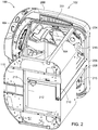
- Air is received in the outside air inlet 201 and is communicated rearward through a horizontal air conduit 204 formed inside the roof 102.
- a vertical conduit 208 is coupled to the air outlet 206 directly behind the operator seat and carries the air vertically downward to a point adjacent to the floor 115.
- the lower end of the vertical conduit 208 is coupled to a further conduit 210.
- Conduit 210 extends around the floor 115 and an exposed lower portion of the air-conditioning module 112 that extends through the floor 115.
- Conduit 210 is in turn coupled to an air inlet 213 on the bottom of the air-conditioning module 112 to communicate air into the air-conditioning module 112. In this manner, a fan in the air-conditioning module 112 sucks air from roof 102, high outside the vehicle, through the outside air inlet 201 and down into the air-conditioning module 112 for conditioning.
- the air-conditioning module 112 is also configured to receive air from inside the operator compartment through the air inlets 118 and to condition it.
- the air-conditioning module 12 includes a fan to suck air into the air-conditioning module 112, and to blow air out of the air-conditioning module 112.
- the air-conditioning module 112 further includes a means for conditioning the air passing their through, which can include heat exchangers for conveying engine heat to the air being conditioned (i.e. heating the air). It can also include heat exchangers such as evaporators for conveying heat out of the air being conditioned (i.e. cooling the air). It can also include various vents, flaps and internal conduits to direct the air between the various inlets and outlets of the air-conditioning module 112 and through the various air-conditioning elements. These various internal elements are of conventional arrangement.
- Air that has been conditioned in the air-conditioning module 112 is directed out of the air-conditioning module 112 and through air outlets 212 adjacent to the floor 115 to enter the operator compartment directly.
- Air that has been conditioned in the air-conditioning module 112 is also directed out of the air-conditioning module 112 and into the rear vertical conduit 114, which carries the air upward and into the roof 102 at a location above and directly behind the operator.
- the air received into the roof 102 is communicated forward and to each side of the vehicle through conduits 214 formed in the roof 102.
- Air outlets 215 disposed in the roof 102 receive air from the conduits 214 and pass the conditioned air into the operator compartment at the roof level. Further details of the construction of the air conduits in the roof 102 can be found in the patent application entitled "Roof for a Work Vehicle" (docket number P22942-US-PRI) filed contemporaneously herewith.
- the air-conditioning module 112 is of conventional arrangement, having operator controls that are configured to alternatively and selectively heat and cool the air in the operator compartment.
- the operator can select heating or cooling.
- the operator can select a desired source of air and air inlet (i.e. outside air inlet 201 or inside air inlet 118).
- the operator can also select the desired conditioned air outlets 215 in the roof, or air outlet 212 adjacent to the floor.
- the operator controls by which the operator makes these selections of airflow and air temperature are disposed inside the operator compartment and are configured in a conventional manner.
Landscapes
- Engineering & Computer Science (AREA)
- Mechanical Engineering (AREA)
- Physics & Mathematics (AREA)
- Thermal Sciences (AREA)
- Chemical & Material Sciences (AREA)
- Combustion & Propulsion (AREA)
- Transportation (AREA)
- Air-Conditioning For Vehicles (AREA)
- Body Structure For Vehicles (AREA)
- Automatic Assembly (AREA)
Claims (5)
- Bedienerstation (100) für ein Arbeitsfahrzeug, Folgendes umfassend:ein Dach (102), wobei das Dach (102) einen ersten Klimaanlagenauslass definiert;einen Boden (115), der unter dem Dach (102) angeordnet ist;mehrere Fenster (106), die sich zwischen dem Boden (115) und dem Dach (102) erstrecken und zusammen mit dem Boden (115) und dem Dach (102) einen Bedienerraum definieren, der auf allen Seiten umschlossen ist;einen Bedienersitz (108), der auf dem Boden (115) getragen wird und im Bedienerraum angeordnet ist;ein Klimaanlagenmodul (112), das an den Boden (115) angrenzend angeordnet ist, wobei das Klimaanlagenmodul (112) einen ersten Lufteinlass und einen ersten Klimaanlagenauslass aufweist;eine erste Luftleitung (208), die sich zwischen einem Umgebungslufteinlass (201), der dazu eingerichtet ist, Umgebungsluft aufzunehmen, und dem Klimaanlagenmodul (112) erstreckt und dazu ausgelegt ist, Umgebungsluft vom Umgebungslufteinlass (201) in den ersten Lufteinlass des Klimaanlagenmoduls (112) zu leiten; undeine zweite Luftleitung (114), die sich zwischen dem ersten Klimaanlagenauslass des Klimaanlagenmoduls (112) und dem ersten Klimaanlagenauslass des Dachs (102) erstreckt und dazu ausgelegt ist, Klimaanlagenluft vom Klimaanlagenmodul (112) zum ersten Klimaanlagenauslass des Dachs (102) zu leiten, wobei die zweite Luftleitung (114) einen zweiten im Allgemeinen vertikalen Leitungsabschnitt enthält, der hinter dem Bedienersitz (108) angeordnet ist, dadurch gekennzeichnet, dass das Dach (102) den Umgebungslufteinlass (201) definiert und dass die erste Luftleitung (208) einen ersten im Allgemeinen vertikalen Leitungsabschnitt enthält, der hinter dem Bedienersitz (108) angeordnet ist.
- Bedienerstation (100) nach Anspruch 1, wobei das Klimaanlagenmodul (112) eine zweite Lufteinlassöffnung aufweist, die sich direkt in den Bedienerraum öffnet, wobei der zweite Lufteinlass an den Boden (115) angrenzend angeordnet ist.
- Bedienerstation (100) nach Anspruch 1, wobei das Klimaanlagenmodul (112) einen zweiten Klimaanlagenauslass aufweist, der sich direkt in den Bedienerraum öffnet, wobei der zweite Klimaanlagenauslass des Klimaanlagenmoduls (112) an den Boden angrenzend (115) angeordnet ist.
- Bedienerstation (100) nach Anspruch 2, wobei der erste im Allgemeinen vertikale Leitungsabschnitt mit einem ersten im Allgemeinen horizontalen Luftleitungsabschnitt gekoppelt ist und ferner wobei der erste im Allgemeinen horizontale Luftleitungsabschnitt im Dach (102) angeordnet ist.
- Arbeitsfahrzeug mit einer Bedienerstation (100) nach einem der vorstehenden Ansprüche.
Applications Claiming Priority (1)
| Application Number | Priority Date | Filing Date | Title |
|---|---|---|---|
| US14/747,008 US9821629B2 (en) | 2015-06-23 | 2015-06-23 | Operator station |
Publications (2)
| Publication Number | Publication Date |
|---|---|
| EP3109075A1 EP3109075A1 (de) | 2016-12-28 |
| EP3109075B1 true EP3109075B1 (de) | 2019-11-20 |
Family
ID=56024122
Family Applications (1)
| Application Number | Title | Priority Date | Filing Date |
|---|---|---|---|
| EP16169886.5A Active EP3109075B1 (de) | 2015-06-23 | 2016-05-17 | Bedienerstation |
Country Status (3)
| Country | Link |
|---|---|
| US (1) | US9821629B2 (de) |
| EP (1) | EP3109075B1 (de) |
| BR (1) | BR102016014630B1 (de) |
Families Citing this family (7)
| Publication number | Priority date | Publication date | Assignee | Title |
|---|---|---|---|---|
| JP2016030559A (ja) * | 2014-07-30 | 2016-03-07 | ヤンマー株式会社 | 作業車両 |
| DE102018206111A1 (de) | 2018-04-20 | 2019-10-24 | Deere & Company | Dachstruktur |
| JP7131173B2 (ja) * | 2018-07-27 | 2022-09-06 | コベルコ建機株式会社 | 建設機械のキャブ |
| JP6942106B2 (ja) * | 2018-09-25 | 2021-09-29 | 日立建機株式会社 | 作業機械の運転室及び作業機械 |
| EP3984822A4 (de) * | 2019-06-11 | 2023-07-05 | Kubota Corporation | Schutzvorrichtung für arbeitsfahrzeug und mit dieser ausgestattetes arbeitsfahrzeug |
| US11486460B2 (en) | 2019-08-27 | 2022-11-01 | Deere & Company | Work vehicle with tuned mass dampers |
| JP7477376B2 (ja) * | 2020-06-09 | 2024-05-01 | 日立建機株式会社 | 作業機械 |
Family Cites Families (18)
| Publication number | Priority date | Publication date | Assignee | Title |
|---|---|---|---|---|
| US4344356A (en) * | 1980-06-23 | 1982-08-17 | Deere & Company | Air distribution system |
| US4531453A (en) * | 1983-05-16 | 1985-07-30 | Deere & Company | Atmosphere control arrangement for an operator enclosure |
| DE4001148A1 (de) * | 1990-01-17 | 1991-07-18 | Deere & Co | Belueftungseinrichtung fuer fahrzeugkabine |
| JPH08119155A (ja) | 1994-10-24 | 1996-05-14 | Kubota Corp | キャビン付トラクタの空調装置 |
| US6398294B1 (en) * | 2000-06-06 | 2002-06-04 | Deere & Company | Easy access HVAC module on work vehicle |
| JP2004352085A (ja) | 2003-05-29 | 2004-12-16 | Denso Corp | 車両用空調装置 |
| DE10362300B4 (de) * | 2003-11-18 | 2013-06-20 | Volkswagen Ag | Belüftungseinrichtung für einen Fahrzeuginnenraum eines Fahrzeuges, insbesondere eines Nutzfahrzeuges |
| US20070205633A1 (en) * | 2006-03-01 | 2007-09-06 | Waco Douglas L | Roof system with integrated hvac ducting |
| US7334834B2 (en) * | 2006-03-09 | 2008-02-26 | Deere & Company | Tractor cab roof with integral HVAC air ducts |
| DE102008005186A1 (de) | 2008-01-18 | 2009-07-23 | Claas Selbstfahrende Erntemaschinen Gmbh | Selbstfahrende Arbeitsmaschine mit einer Fahrzeugkabine |
| GB2466766A (en) * | 2008-10-27 | 2010-07-07 | Agco Gmbh | Tractor cab with cavity floor for HVAC unit and ducting |
| GB0822586D0 (en) * | 2008-12-11 | 2009-01-14 | Agco Gmbh | Tractor cab heating and ventilating systems |
| US8485589B2 (en) * | 2010-03-30 | 2013-07-16 | Kubota Corporation | Cabin system |
| IT1401209B1 (it) | 2010-07-02 | 2013-07-12 | Cnh Italia Spa | Cabina per veicolo agricolo attrezzata con un sistema di ventilazione e di condizionamento dell'aria |
| EP2428376B1 (de) * | 2010-09-14 | 2013-08-21 | CLAAS Tractor SAS | Vormontierte Heckmodule einer Kabine eines Schwerfahrzeugs |
| JP5654145B1 (ja) | 2013-05-15 | 2015-01-14 | 株式会社小松製作所 | キャブ、及び作業車両 |
| DE102014103574A1 (de) | 2014-03-17 | 2015-09-17 | Claas Tractor Sas | Fahrerkabine einer land- oder bauwirtschaftlich nutzbaren Arbeitsmaschine |
| US9346495B2 (en) * | 2014-04-21 | 2016-05-24 | Caterpillar Inc. | Machine cabin having improved operator visibility |
-
2015
- 2015-06-23 US US14/747,008 patent/US9821629B2/en active Active
-
2016
- 2016-05-17 EP EP16169886.5A patent/EP3109075B1/de active Active
- 2016-06-21 BR BR102016014630-5A patent/BR102016014630B1/pt active IP Right Grant
Non-Patent Citations (1)
| Title |
|---|
| None * |
Also Published As
| Publication number | Publication date |
|---|---|
| BR102016014630B1 (pt) | 2022-12-13 |
| EP3109075A1 (de) | 2016-12-28 |
| BR102016014630A8 (pt) | 2018-02-27 |
| US9821629B2 (en) | 2017-11-21 |
| US20160375741A1 (en) | 2016-12-29 |
Similar Documents
| Publication | Publication Date | Title |
|---|---|---|
| EP3109075A1 (de) | Bedienerstation | |
| US11014426B2 (en) | Agricultural vehicle cab fitted with an HVAC system | |
| US5385382A (en) | Combination seat frame and ventilation apparatus | |
| EP0756955B2 (de) | Luftbehandlungssystem für Kraftfahrzeuge | |
| US4612975A (en) | Air conditioning device installed in a cabin of an earth-moving vehicle | |
| WO2012056303A1 (en) | An air-conditioned seat for a cabin of a vehicle | |
| CN109000078B (zh) | 空气导入结构 | |
| US3289564A (en) | Air-conditioning devices for automobile vehicles | |
| CN210478346U (zh) | 用于自动驾驶的车辆 | |
| EP4052614B1 (de) | Baumaschine | |
| US6902473B1 (en) | Vehicle ventilation conduit system | |
| CN109906162B (zh) | 结构车顶围绕物中的通风装置布置和包括这种布置的车辆 | |
| EP2532541A1 (de) | Aufbewahrungsbehälter auf einem Fahrzeug | |
| EP1787835B1 (de) | Dach eines Fahrerhauses, insbesondere für eine landwirtschaftliche Maschine | |
| US20200023708A1 (en) | A conditioned air distribution system for a vehicle | |
| CN200996157Y (zh) | 用于工程机械车辆的驾驶室及包括其的车辆 | |
| US20090042501A1 (en) | Localized Air Distribution System | |
| EP2428376B1 (de) | Vormontierte Heckmodule einer Kabine eines Schwerfahrzeugs | |
| CN210617786U (zh) | 双空调温控装置及车辆 | |
| US20250367999A1 (en) | Localized hvac systems for recreational vehicles and methods for same | |
| CN223982369U (zh) | 一种车身、车辆内置空调风道结构及车辆 | |
| EP4722008A1 (de) | Luftstromoptimierung für kabinenkomfort | |
| CN112776558B (zh) | 空调装置以及车辆 | |
| EP1382471A1 (de) | Luftverteilsystem für den Fahrgastraum eines Kraftfahrzeuges | |
| JPH11334415A (ja) | インストルメントパネル |
Legal Events
| Date | Code | Title | Description |
|---|---|---|---|
| PUAI | Public reference made under article 153(3) epc to a published international application that has entered the european phase |
Free format text: ORIGINAL CODE: 0009012 |
|
| STAA | Information on the status of an ep patent application or granted ep patent |
Free format text: STATUS: THE APPLICATION HAS BEEN PUBLISHED |
|
| AK | Designated contracting states |
Kind code of ref document: A1 Designated state(s): AL AT BE BG CH CY CZ DE DK EE ES FI FR GB GR HR HU IE IS IT LI LT LU LV MC MK MT NL NO PL PT RO RS SE SI SK SM TR |
|
| AX | Request for extension of the european patent |
Extension state: BA ME |
|
| STAA | Information on the status of an ep patent application or granted ep patent |
Free format text: STATUS: REQUEST FOR EXAMINATION WAS MADE |
|
| 17P | Request for examination filed |
Effective date: 20170628 |
|
| RBV | Designated contracting states (corrected) |
Designated state(s): AL AT BE BG CH CY CZ DE DK EE ES FI FR GB GR HR HU IE IS IT LI LT LU LV MC MK MT NL NO PL PT RO RS SE SI SK SM TR |
|
| STAA | Information on the status of an ep patent application or granted ep patent |
Free format text: STATUS: EXAMINATION IS IN PROGRESS |
|
| 17Q | First examination report despatched |
Effective date: 20190423 |
|
| GRAP | Despatch of communication of intention to grant a patent |
Free format text: ORIGINAL CODE: EPIDOSNIGR1 |
|
| STAA | Information on the status of an ep patent application or granted ep patent |
Free format text: STATUS: GRANT OF PATENT IS INTENDED |
|
| INTG | Intention to grant announced |
Effective date: 20190614 |
|
| GRAS | Grant fee paid |
Free format text: ORIGINAL CODE: EPIDOSNIGR3 |
|
| GRAA | (expected) grant |
Free format text: ORIGINAL CODE: 0009210 |
|
| STAA | Information on the status of an ep patent application or granted ep patent |
Free format text: STATUS: THE PATENT HAS BEEN GRANTED |
|
| AK | Designated contracting states |
Kind code of ref document: B1 Designated state(s): AL AT BE BG CH CY CZ DE DK EE ES FI FR GB GR HR HU IE IS IT LI LT LU LV MC MK MT NL NO PL PT RO RS SE SI SK SM TR |
|
| REG | Reference to a national code |
Ref country code: GB Ref legal event code: FG4D |
|
| REG | Reference to a national code |
Ref country code: CH Ref legal event code: EP |
|
| REG | Reference to a national code |
Ref country code: IE Ref legal event code: FG4D |
|
| REG | Reference to a national code |
Ref country code: DE Ref legal event code: R096 Ref document number: 602016024529 Country of ref document: DE |
|
| REG | Reference to a national code |
Ref country code: AT Ref legal event code: REF Ref document number: 1203790 Country of ref document: AT Kind code of ref document: T Effective date: 20191215 |
|
| REG | Reference to a national code |
Ref country code: NL Ref legal event code: MP Effective date: 20191120 |
|
| REG | Reference to a national code |
Ref country code: LT Ref legal event code: MG4D |
|
| PG25 | Lapsed in a contracting state [announced via postgrant information from national office to epo] |
Ref country code: LV Free format text: LAPSE BECAUSE OF FAILURE TO SUBMIT A TRANSLATION OF THE DESCRIPTION OR TO PAY THE FEE WITHIN THE PRESCRIBED TIME-LIMIT Effective date: 20191120 Ref country code: SE Free format text: LAPSE BECAUSE OF FAILURE TO SUBMIT A TRANSLATION OF THE DESCRIPTION OR TO PAY THE FEE WITHIN THE PRESCRIBED TIME-LIMIT Effective date: 20191120 Ref country code: NL Free format text: LAPSE BECAUSE OF FAILURE TO SUBMIT A TRANSLATION OF THE DESCRIPTION OR TO PAY THE FEE WITHIN THE PRESCRIBED TIME-LIMIT Effective date: 20191120 Ref country code: LT Free format text: LAPSE BECAUSE OF FAILURE TO SUBMIT A TRANSLATION OF THE DESCRIPTION OR TO PAY THE FEE WITHIN THE PRESCRIBED TIME-LIMIT Effective date: 20191120 Ref country code: GR Free format text: LAPSE BECAUSE OF FAILURE TO SUBMIT A TRANSLATION OF THE DESCRIPTION OR TO PAY THE FEE WITHIN THE PRESCRIBED TIME-LIMIT Effective date: 20200221 Ref country code: NO Free format text: LAPSE BECAUSE OF FAILURE TO SUBMIT A TRANSLATION OF THE DESCRIPTION OR TO PAY THE FEE WITHIN THE PRESCRIBED TIME-LIMIT Effective date: 20200220 Ref country code: FI Free format text: LAPSE BECAUSE OF FAILURE TO SUBMIT A TRANSLATION OF THE DESCRIPTION OR TO PAY THE FEE WITHIN THE PRESCRIBED TIME-LIMIT Effective date: 20191120 Ref country code: BG Free format text: LAPSE BECAUSE OF FAILURE TO SUBMIT A TRANSLATION OF THE DESCRIPTION OR TO PAY THE FEE WITHIN THE PRESCRIBED TIME-LIMIT Effective date: 20200220 |
|
| PG25 | Lapsed in a contracting state [announced via postgrant information from national office to epo] |
Ref country code: RS Free format text: LAPSE BECAUSE OF FAILURE TO SUBMIT A TRANSLATION OF THE DESCRIPTION OR TO PAY THE FEE WITHIN THE PRESCRIBED TIME-LIMIT Effective date: 20191120 Ref country code: HR Free format text: LAPSE BECAUSE OF FAILURE TO SUBMIT A TRANSLATION OF THE DESCRIPTION OR TO PAY THE FEE WITHIN THE PRESCRIBED TIME-LIMIT Effective date: 20191120 Ref country code: IS Free format text: LAPSE BECAUSE OF FAILURE TO SUBMIT A TRANSLATION OF THE DESCRIPTION OR TO PAY THE FEE WITHIN THE PRESCRIBED TIME-LIMIT Effective date: 20200320 |
|
| PG25 | Lapsed in a contracting state [announced via postgrant information from national office to epo] |
Ref country code: AL Free format text: LAPSE BECAUSE OF FAILURE TO SUBMIT A TRANSLATION OF THE DESCRIPTION OR TO PAY THE FEE WITHIN THE PRESCRIBED TIME-LIMIT Effective date: 20191120 |
|
| PG25 | Lapsed in a contracting state [announced via postgrant information from national office to epo] |
Ref country code: RO Free format text: LAPSE BECAUSE OF FAILURE TO SUBMIT A TRANSLATION OF THE DESCRIPTION OR TO PAY THE FEE WITHIN THE PRESCRIBED TIME-LIMIT Effective date: 20191120 Ref country code: CZ Free format text: LAPSE BECAUSE OF FAILURE TO SUBMIT A TRANSLATION OF THE DESCRIPTION OR TO PAY THE FEE WITHIN THE PRESCRIBED TIME-LIMIT Effective date: 20191120 Ref country code: PT Free format text: LAPSE BECAUSE OF FAILURE TO SUBMIT A TRANSLATION OF THE DESCRIPTION OR TO PAY THE FEE WITHIN THE PRESCRIBED TIME-LIMIT Effective date: 20200412 Ref country code: EE Free format text: LAPSE BECAUSE OF FAILURE TO SUBMIT A TRANSLATION OF THE DESCRIPTION OR TO PAY THE FEE WITHIN THE PRESCRIBED TIME-LIMIT Effective date: 20191120 Ref country code: DK Free format text: LAPSE BECAUSE OF FAILURE TO SUBMIT A TRANSLATION OF THE DESCRIPTION OR TO PAY THE FEE WITHIN THE PRESCRIBED TIME-LIMIT Effective date: 20191120 Ref country code: ES Free format text: LAPSE BECAUSE OF FAILURE TO SUBMIT A TRANSLATION OF THE DESCRIPTION OR TO PAY THE FEE WITHIN THE PRESCRIBED TIME-LIMIT Effective date: 20191120 |
|
| REG | Reference to a national code |
Ref country code: AT Ref legal event code: MK05 Ref document number: 1203790 Country of ref document: AT Kind code of ref document: T Effective date: 20191120 |
|
| REG | Reference to a national code |
Ref country code: DE Ref legal event code: R097 Ref document number: 602016024529 Country of ref document: DE |
|
| PG25 | Lapsed in a contracting state [announced via postgrant information from national office to epo] |
Ref country code: SK Free format text: LAPSE BECAUSE OF FAILURE TO SUBMIT A TRANSLATION OF THE DESCRIPTION OR TO PAY THE FEE WITHIN THE PRESCRIBED TIME-LIMIT Effective date: 20191120 Ref country code: SM Free format text: LAPSE BECAUSE OF FAILURE TO SUBMIT A TRANSLATION OF THE DESCRIPTION OR TO PAY THE FEE WITHIN THE PRESCRIBED TIME-LIMIT Effective date: 20191120 |
|
| PLBE | No opposition filed within time limit |
Free format text: ORIGINAL CODE: 0009261 |
|
| STAA | Information on the status of an ep patent application or granted ep patent |
Free format text: STATUS: NO OPPOSITION FILED WITHIN TIME LIMIT |
|
| 26N | No opposition filed |
Effective date: 20200821 |
|
| PG25 | Lapsed in a contracting state [announced via postgrant information from national office to epo] |
Ref country code: PL Free format text: LAPSE BECAUSE OF FAILURE TO SUBMIT A TRANSLATION OF THE DESCRIPTION OR TO PAY THE FEE WITHIN THE PRESCRIBED TIME-LIMIT Effective date: 20191120 Ref country code: AT Free format text: LAPSE BECAUSE OF FAILURE TO SUBMIT A TRANSLATION OF THE DESCRIPTION OR TO PAY THE FEE WITHIN THE PRESCRIBED TIME-LIMIT Effective date: 20191120 Ref country code: SI Free format text: LAPSE BECAUSE OF FAILURE TO SUBMIT A TRANSLATION OF THE DESCRIPTION OR TO PAY THE FEE WITHIN THE PRESCRIBED TIME-LIMIT Effective date: 20191120 |
|
| PG25 | Lapsed in a contracting state [announced via postgrant information from national office to epo] |
Ref country code: IT Free format text: LAPSE BECAUSE OF FAILURE TO SUBMIT A TRANSLATION OF THE DESCRIPTION OR TO PAY THE FEE WITHIN THE PRESCRIBED TIME-LIMIT Effective date: 20191120 Ref country code: LI Free format text: LAPSE BECAUSE OF NON-PAYMENT OF DUE FEES Effective date: 20200531 Ref country code: CH Free format text: LAPSE BECAUSE OF NON-PAYMENT OF DUE FEES Effective date: 20200531 Ref country code: MC Free format text: LAPSE BECAUSE OF FAILURE TO SUBMIT A TRANSLATION OF THE DESCRIPTION OR TO PAY THE FEE WITHIN THE PRESCRIBED TIME-LIMIT Effective date: 20191120 |
|
| REG | Reference to a national code |
Ref country code: BE Ref legal event code: MM Effective date: 20200531 |
|
| GBPC | Gb: european patent ceased through non-payment of renewal fee |
Effective date: 20200517 |
|
| PG25 | Lapsed in a contracting state [announced via postgrant information from national office to epo] |
Ref country code: LU Free format text: LAPSE BECAUSE OF NON-PAYMENT OF DUE FEES Effective date: 20200517 |
|
| PG25 | Lapsed in a contracting state [announced via postgrant information from national office to epo] |
Ref country code: FR Free format text: LAPSE BECAUSE OF NON-PAYMENT OF DUE FEES Effective date: 20200531 Ref country code: GB Free format text: LAPSE BECAUSE OF NON-PAYMENT OF DUE FEES Effective date: 20200517 Ref country code: IE Free format text: LAPSE BECAUSE OF NON-PAYMENT OF DUE FEES Effective date: 20200517 |
|
| PG25 | Lapsed in a contracting state [announced via postgrant information from national office to epo] |
Ref country code: BE Free format text: LAPSE BECAUSE OF NON-PAYMENT OF DUE FEES Effective date: 20200531 |
|
| PG25 | Lapsed in a contracting state [announced via postgrant information from national office to epo] |
Ref country code: TR Free format text: LAPSE BECAUSE OF FAILURE TO SUBMIT A TRANSLATION OF THE DESCRIPTION OR TO PAY THE FEE WITHIN THE PRESCRIBED TIME-LIMIT Effective date: 20191120 Ref country code: MT Free format text: LAPSE BECAUSE OF FAILURE TO SUBMIT A TRANSLATION OF THE DESCRIPTION OR TO PAY THE FEE WITHIN THE PRESCRIBED TIME-LIMIT Effective date: 20191120 Ref country code: CY Free format text: LAPSE BECAUSE OF FAILURE TO SUBMIT A TRANSLATION OF THE DESCRIPTION OR TO PAY THE FEE WITHIN THE PRESCRIBED TIME-LIMIT Effective date: 20191120 |
|
| PG25 | Lapsed in a contracting state [announced via postgrant information from national office to epo] |
Ref country code: MK Free format text: LAPSE BECAUSE OF FAILURE TO SUBMIT A TRANSLATION OF THE DESCRIPTION OR TO PAY THE FEE WITHIN THE PRESCRIBED TIME-LIMIT Effective date: 20191120 |
|
| PGFP | Annual fee paid to national office [announced via postgrant information from national office to epo] |
Ref country code: DE Payment date: 20250423 Year of fee payment: 10 |