EP3109146A2 - Cadre de bicyclette à support de batterie amélioré - Google Patents
Cadre de bicyclette à support de batterie amélioré Download PDFInfo
- Publication number
- EP3109146A2 EP3109146A2 EP16176239.8A EP16176239A EP3109146A2 EP 3109146 A2 EP3109146 A2 EP 3109146A2 EP 16176239 A EP16176239 A EP 16176239A EP 3109146 A2 EP3109146 A2 EP 3109146A2
- Authority
- EP
- European Patent Office
- Prior art keywords
- battery
- boss
- frame
- mount
- bicycle
- Prior art date
- Legal status (The legal status is an assumption and is not a legal conclusion. Google has not performed a legal analysis and makes no representation as to the accuracy of the status listed.)
- Granted
Links
Images








Classifications
-
- B—PERFORMING OPERATIONS; TRANSPORTING
- B62—LAND VEHICLES FOR TRAVELLING OTHERWISE THAN ON RAILS
- B62M—RIDER PROPULSION OF WHEELED VEHICLES OR SLEDGES; POWERED PROPULSION OF SLEDGES OR SINGLE-TRACK CYCLES; TRANSMISSIONS SPECIALLY ADAPTED FOR SUCH VEHICLES
- B62M6/00—Rider propulsion of wheeled vehicles with additional source of power, e.g. combustion engine or electric motor
- B62M6/80—Accessories, e.g. power sources; Arrangements thereof
- B62M6/90—Batteries
-
- B—PERFORMING OPERATIONS; TRANSPORTING
- B62—LAND VEHICLES FOR TRAVELLING OTHERWISE THAN ON RAILS
- B62K—CYCLES; CYCLE FRAMES; CYCLE STEERING DEVICES; RIDER-OPERATED TERMINAL CONTROLS SPECIALLY ADAPTED FOR CYCLES; CYCLE AXLE SUSPENSIONS; CYCLE SIDECARS, FORECARS, OR THE LIKE
- B62K11/00—Motorcycles, engine-assisted cycles or motor scooters with one or two wheels
- B62K11/02—Frames
- B62K11/04—Frames characterised by the engine being between front and rear wheels
-
- B—PERFORMING OPERATIONS; TRANSPORTING
- B62—LAND VEHICLES FOR TRAVELLING OTHERWISE THAN ON RAILS
- B62M—RIDER PROPULSION OF WHEELED VEHICLES OR SLEDGES; POWERED PROPULSION OF SLEDGES OR SINGLE-TRACK CYCLES; TRANSMISSIONS SPECIALLY ADAPTED FOR SUCH VEHICLES
- B62M6/00—Rider propulsion of wheeled vehicles with additional source of power, e.g. combustion engine or electric motor
- B62M6/40—Rider propelled cycles with auxiliary electric motor
-
- H—ELECTRICITY
- H01—ELECTRIC ELEMENTS
- H01M—PROCESSES OR MEANS, e.g. BATTERIES, FOR THE DIRECT CONVERSION OF CHEMICAL ENERGY INTO ELECTRICAL ENERGY
- H01M50/00—Constructional details or processes of manufacture of the non-active parts of electrochemical cells other than fuel cells, e.g. hybrid cells
- H01M50/20—Mountings; Secondary casings or frames; Racks, modules or packs; Suspension devices; Shock absorbers; Transport or carrying devices; Holders
- H01M50/249—Mountings; Secondary casings or frames; Racks, modules or packs; Suspension devices; Shock absorbers; Transport or carrying devices; Holders specially adapted for aircraft or vehicles, e.g. cars or trains
-
- B—PERFORMING OPERATIONS; TRANSPORTING
- B62—LAND VEHICLES FOR TRAVELLING OTHERWISE THAN ON RAILS
- B62K—CYCLES; CYCLE FRAMES; CYCLE STEERING DEVICES; RIDER-OPERATED TERMINAL CONTROLS SPECIALLY ADAPTED FOR CYCLES; CYCLE AXLE SUSPENSIONS; CYCLE SIDECARS, FORECARS, OR THE LIKE
- B62K25/00—Axle suspensions
- B62K25/04—Axle suspensions for mounting axles resiliently on cycle frame or fork
- B62K25/28—Axle suspensions for mounting axles resiliently on cycle frame or fork with pivoted chain-stay
- B62K25/286—Axle suspensions for mounting axles resiliently on cycle frame or fork with pivoted chain-stay the shock absorber being connected to the chain-stay via a linkage mechanism
-
- B—PERFORMING OPERATIONS; TRANSPORTING
- B62—LAND VEHICLES FOR TRAVELLING OTHERWISE THAN ON RAILS
- B62M—RIDER PROPULSION OF WHEELED VEHICLES OR SLEDGES; POWERED PROPULSION OF SLEDGES OR SINGLE-TRACK CYCLES; TRANSMISSIONS SPECIALLY ADAPTED FOR SUCH VEHICLES
- B62M6/00—Rider propulsion of wheeled vehicles with additional source of power, e.g. combustion engine or electric motor
- B62M6/40—Rider propelled cycles with auxiliary electric motor
- B62M6/45—Control or actuating devices therefor
-
- B—PERFORMING OPERATIONS; TRANSPORTING
- B62—LAND VEHICLES FOR TRAVELLING OTHERWISE THAN ON RAILS
- B62M—RIDER PROPULSION OF WHEELED VEHICLES OR SLEDGES; POWERED PROPULSION OF SLEDGES OR SINGLE-TRACK CYCLES; TRANSMISSIONS SPECIALLY ADAPTED FOR SUCH VEHICLES
- B62M6/00—Rider propulsion of wheeled vehicles with additional source of power, e.g. combustion engine or electric motor
- B62M6/40—Rider propelled cycles with auxiliary electric motor
- B62M6/55—Rider propelled cycles with auxiliary electric motor power-driven at crank shafts parts
-
- H—ELECTRICITY
- H01—ELECTRIC ELEMENTS
- H01M—PROCESSES OR MEANS, e.g. BATTERIES, FOR THE DIRECT CONVERSION OF CHEMICAL ENERGY INTO ELECTRICAL ENERGY
- H01M2220/00—Batteries for particular applications
- H01M2220/20—Batteries in motive systems, e.g. vehicle, ship, plane
-
- Y—GENERAL TAGGING OF NEW TECHNOLOGICAL DEVELOPMENTS; GENERAL TAGGING OF CROSS-SECTIONAL TECHNOLOGIES SPANNING OVER SEVERAL SECTIONS OF THE IPC; TECHNICAL SUBJECTS COVERED BY FORMER USPC CROSS-REFERENCE ART COLLECTIONS [XRACs] AND DIGESTS
- Y02—TECHNOLOGIES OR APPLICATIONS FOR MITIGATION OR ADAPTATION AGAINST CLIMATE CHANGE
- Y02E—REDUCTION OF GREENHOUSE GAS [GHG] EMISSIONS, RELATED TO ENERGY GENERATION, TRANSMISSION OR DISTRIBUTION
- Y02E60/00—Enabling technologies; Technologies with a potential or indirect contribution to GHG emissions mitigation
- Y02E60/10—Energy storage using batteries
Definitions
- the present invention relates to bicycle frames and specifically to a bicycle frame that is adapted to support a battery, such as for powering an electric motor.
- the present invention provides a bicycle comprising a pivot interface between a battery and a frame.
- the pivot interface includes a pivot mount defining a recess on one of the frame and the battery, and an eccentric boss on the other of the frame and the battery.
- the boss has a first boss width that is insertable into the recess when the battery is in a first position, and the boss further has a second boss width larger than the first boss width and creating an interference fit with the recess when the battery is in a second position.
- At least one of the pivot mount and the boss is resilient in order to accommodate the interference fit.
- the pivot mount is on the frame and the boss is on the battery, and also the pivot mount preferably comprises a resilient material.
- the eccentric boss comprises an elongated shaft rotatable in the recess, and the shaft has a cam profile with a low point defining the first boss width and a high point defining the second boss width.
- the shaft can define a central axis and the cam profile is symmetrically positioned around the central axis.
- the pivot interface can be positioned adjacent one end of the battery, and an opposite end of the battery can include an opening.
- the bicycle further preferably comprises a through axle positioned through the opening and through a portion of the frame to secure the opposite end of the battery to the frame.
- a protective cover can be positioned to protect a portion of the battery.
- the protective cover can be detachably secured to the battery.
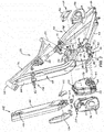
- Figs. 1-3 illustrate a bicycle 20 embodying the present invention.
- the illustrated bicycle 20 includes a front wheel 22 and a rear wheel 24 that cooperatively define a central plane 26 and forward and rearward directions.
- a front fork 28 is supported by the front wheel 22, and a frame 30 is supported by the front fork 28 and the rear wheel 24.
- the illustrated frame 30 includes a head tube 32 rotationally coupled to the front fork 28, a down tube 34 extending downward and rearward from the head tube 32, a top tube 36 extending rearward from the head tube 32, a seat tube 38 extending downward from the top tube 36, and a motor mount 40 connecting the down tube 34 and the seat tube 38.
- the frame 30 further comprises a rear suspension assembly 42 including chainstays 44, rear wheel mounts 46, seat stays 48, and a rear shock 50, the functions of which are well known in the art.
- the illustrated bicycle 20 further includes an electric motor 52 adapted to provide power to the bicycle 20.
- the illustrated electric motor 52 includes three mounting studs 54 for securing the electric motor 52 to the frame 30 via mounting nuts 55.
- the electric motor 52 further includes a drive shaft 56 connected to left and right cranks 58 that are adapted to receive corresponding pedals 59 that facilitate pedaling of the bicycle 20 by a user.
- Power is provided to the electric motor 52 via a battery 60 mounted within a tube recess 62 in the down tube 34, as explained below in more detail.
- the motor mount 40 includes a down tube mount 64 coupled to the down tube 34, a seat tube mount 66 coupled to the seat tube 38, and a chainstay mount 68 coupled to the chainstays 44.
- the illustrated down tube mount 64 and seat tube mount 66 are welded to the down tube 34 and seat tube 38, respectively, but any suitable connection (e.g., bonding, fastening, or unitary construction) will suffice.
- the illustrated chainstay mount 68 comprises a pivot mount 70 for pivotally connecting the motor mount 40 to the chainstays 44 using a pivot shaft 72.
- the motor mount 40 further includes a side brace 74 connecting the down tube mount 64 to the chainstay mount 68 along the left side of the electric motor 52.
- the side brace 74 is positioned to structurally and visually extend from the down tube 34 directly toward the chainstay mount 68.
- the right side of the motor mount 40 does not include a side brace 74 and is completely open to facilitate insertion and removal of the electric motor 52 from the motor mount 40.
- the motor mount 40 further includes an upper support 76 connecting the down tube mount 64 with the seat tube mount 66, a rear support 78 connecting the seat tube mount 66 with the chainstay mount 68, and a lower support 80 connecting the down tube mount 64 with the chainstay mount 68.
- the upper support 76 includes an upper flange 82 aligned with the central plane 26 and including a flange opening 84 adapted to receive one of the mounting studs 54 in order to facilitate attachment of the electric motor 52 to the motor mount 40 by the mounting nuts 55.
- the lower support 80 includes a lower flange 85 aligned with the central plane 26 and including two flange openings 84 adapted to receive two of the mounting studs 54 in order to facilitate attachment of the electric motor 52 to the motor mount 40.
- the combination of the down tube mount 64, the upper support 76 the seat tube mount 66, the rear support 78, the chainstay mount 68, and the lower support 80 provides complete enclosure of the electric motor 52 along the central plane 26 of the bicycle 20.
- This arrangement provides structural integrity to the bicycle frame 30 and also helps to protect the electric motor 52 from damage that could be caused by impact of the bicycle 20 with other objects (e.g., rocks or logs).
- This arrangement also utilizes the electric motor 52 as a stressed member to further improve the strength and rigidity of the bicycle frame 30.
- the structural arrangement of the motor mount 40 results in an upper left opening 86, a lower left opening 88, and a right opening 90. These openings are fitted with an upper left cover 92, a lower left cover 94 and a right cover 96, respectively.
- Each of the upper support 76, lower support 80, and rear support 78 includes threaded openings 98 for receiving threaded fasteners 100 that attach the covers to the motor mount 40. The covers protect the electric motor 52 from damage and debris infiltrating the electric motor 52.
- the illustrated battery 60 includes an upper battery mount 102 and a lower battery mount 104 that facilitates securing the battery 60 to the bicycle frame 30 at an upper frame mount 106 and a lower frame mount 108, respectively.
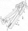
- the lower battery mount 104 is first engaged with the lower frame mount 108 with the battery 60 in a partially attached position, as shown in Fig. 7 .
- the battery 60 is then pivoted upwardly toward the frame 30 to a fully attached position, as shown in Fig. 8 and described below in more detail.
- the lower battery mount 104 and lower frame mount 108 define a pivot interface between the battery 60 and the frame 30.
- the lower battery mount 104 comprises an eccentric boss 110 adapted to engage the lower frame mount 108.
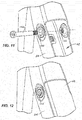
- the eccentric boss 110 comprises an elongated shaft having a cam profile with a low point 112 defining a first boss width W1 and a high point 114 defining a second boss width W2 larger than the first boss width.
- the illustrated lower frame mount 108 defines a depression in the form of a slot 116 that is dimensioned to receive the eccentric boss 110.
- the slot 116 has a width that is dimensioned to easily receive the first boss width W1 of the eccentric boss 110. This is the orientation of the eccentric boss 110 that will be presented to the lower frame mount 108 when the battery 60 is in the partially attached position of Figs. 7 and 9 .
- the cam profile of the eccentric boss 110 is rotated such that the second boss width W2 of the eccentric boss 110 is presented to the slot 116 of the lower frame mount 108, thereby wedging the eccentric boss 110 in the lower frame mount 108, as shown in Figs.
- the lower frame mount 108 is resilient (e.g., made from a resilient material such as polyurethane or resiliently mounted, such as spring-biased).
- the resilient slot 116 configuration of the lower frame mount 108 will inherently accommodate slight differences in battery 60 lengths. It should be understood that the positions of the eccentric boss 110 and depression could be reversed (i.e., the depression could be positioned on the battery 60 and the eccentric boss 110 could be positioned on the frame 30).
- the eccentric boss 110 could be made of a resilient material instead of or in addition to the lower frame mount 108.
- the upper battery mount 102 comprises a battery hole 118 extending all the way through the battery 60
- the upper frame mount 106 includes tube holes 120 through the left and right walls of the down tube 34 adjacent an upper end of the tube recess 62.
- the battery hole 118 of the upper battery mount 102 will be aligned with the tube holes 120 of the upper frame mount 106, and a battery mounting pin 122 can be inserted through the aligned tube holes 120 and battery hole 118 to secure the battery 60 in the fully attached position.
- one of the tube holes 120 is threaded and an end of the battery mounting pin 122 is similarly threaded to secure the mounting pin in place.
- the illustrated bicycle 20 further includes a rock guard 124 secured to and removable from a lower end of the battery 60.
- the rock guard 124 includes a forked end 126 adapted to fit on opposing sides of the lower battery mount 104.
- the forked end 126 of the rock guard 124 is secured to the battery 60 by the same battery fastener 128 that secures the eccentric boss 110 to the battery 60, as best shown in Fig. 3 .
- the rock guard 124 further includes two threaded openings (not shown) facing the battery 60 and adapted to receive fasteners (not shown) that can be inserted through holes in the battery 60 and threaded into the threaded openings 98 in the rock guard 124 to further secure the rock guard 124 to the battery 30.
- the rock guard 124 provides protection to the lower end of the battery 60 and can be easily replaced if damaged.
- the battery 60 further includes a battery control panel 130 that facilitates control of the operation of the battery 60, best seen in Fig. 13 .
- the battery control panel 130 includes a power button 132, a plus button 134 and a minus button 136. These buttons can be used to power the battery 60 on and off and also to select different modes of the battery 60.
- the battery control panel 130 further includes a series of perimeter lights 138 that indicate the battery charge.
- the battery 60 further includes a battery connector 140 on the left side of the battery 60 near the lower battery mount 104.
- the illustrated battery connector 140 can be used both to charge the battery 60 (e.g., with an appropriate charger, not shown) and also to provide connection to the electric motor 52 via a motor connector 142 wired to the electric motor 52.
- the illustrated motor connector 142 includes an overmolded housing 144 that fits into and is flush with the surrounding surfaces.
- the illustrated bicycle 20 further includes a speed sensor 146 secured to an inner face 148 of the left rear wheel 24 support, as illustrated in Fig. 15 .
- the speed sensor senses the rotation of the rear wheel 24, and this information can be used to calculate the speed of the bicycle 20.
- the speed sensor 146 is protected from damage and is further not visible from the left side of the bicycle 20, thus improving aesthetics of the bicycle 20.
- the inside surface of the right cover 96 includes an integral cable channel 150 that facilities routing of a cable through the motor mount 40. More specifically, with the right cover 96 secured to the motor mount 40, the cable channel 150 will be positioned against the electric motor 52, thereby creating a substantially enclosed passageway. With this substantially enclosed passage way, a cable or housing can be inserted into the passage way from the down tube 34 (see arrows in Fig. 16 ) and pushed until it exits adjacent the chainstay mount. This arrangement avoids the need to remove the right cover 96 when threading a new cable or housing through the motor mount 40.
Landscapes
- Engineering & Computer Science (AREA)
- Chemical & Material Sciences (AREA)
- Combustion & Propulsion (AREA)
- Mechanical Engineering (AREA)
- Transportation (AREA)
- Aviation & Aerospace Engineering (AREA)
- Chemical Kinetics & Catalysis (AREA)
- Electrochemistry (AREA)
- General Chemical & Material Sciences (AREA)
- Battery Mounting, Suspending (AREA)
- Arrangement Or Mounting Of Propulsion Units For Vehicles (AREA)
Applications Claiming Priority (1)
| Application Number | Priority Date | Filing Date | Title |
|---|---|---|---|
| US14/752,331 US9580141B2 (en) | 2015-06-26 | 2015-06-26 | Bicycle frame with improved battery mount |
Publications (3)
| Publication Number | Publication Date |
|---|---|
| EP3109146A2 true EP3109146A2 (fr) | 2016-12-28 |
| EP3109146A3 EP3109146A3 (fr) | 2017-01-04 |
| EP3109146B1 EP3109146B1 (fr) | 2019-09-11 |
Family
ID=56235724
Family Applications (1)
| Application Number | Title | Priority Date | Filing Date |
|---|---|---|---|
| EP16176239.8A Active EP3109146B1 (fr) | 2015-06-26 | 2016-06-24 | Cadre de bicyclette à support de batterie amélioré |
Country Status (3)
| Country | Link |
|---|---|
| US (1) | US9580141B2 (fr) |
| EP (1) | EP3109146B1 (fr) |
| TW (1) | TW201702110A (fr) |
Cited By (6)
| Publication number | Priority date | Publication date | Assignee | Title |
|---|---|---|---|---|
| AT15420U1 (de) * | 2016-04-21 | 2017-08-15 | Ktm Fahrrad Gmbh | Fahrradrahmen und Elektrofahrrad hiermit |
| WO2019049136A1 (fr) * | 2017-09-06 | 2019-03-14 | G&A Battery Patent Ltd. | Système antivol pour batterie |
| EP3444176A4 (fr) * | 2017-04-28 | 2019-07-24 | Guangzhou Zhanhui Electronics Co., Ltd. | Tube de cadre de vélo ayant un moteur intégré, cadre de vélo et vélo électrique |
| EP3564112A1 (fr) | 2018-05-03 | 2019-11-06 | YT Industries GmbH | Unité d'accumulateur, ensemble doté d'une unité d'accumulateur et d'un dispositif de logement permettant de loger l'unité d'accumulateur et cadre de bicyclette doté d'un tel ensemble |
| WO2021009681A1 (fr) * | 2019-07-16 | 2021-01-21 | Harley-Davidson Motor Company Group, LLC | Vélo électrique |
| USD929268S1 (en) | 2019-08-20 | 2021-08-31 | Serial 1 Cycle Company, Llc | Bicycle |
Families Citing this family (37)
| Publication number | Priority date | Publication date | Assignee | Title |
|---|---|---|---|---|
| US10730584B2 (en) | 2014-09-11 | 2020-08-04 | Stacyc, Inc. | Convertible motorized running cycle |
| US10518841B2 (en) | 2015-06-26 | 2019-12-31 | Specialized Bicycle Components, Inc. | Ebike battery mount |
| CN205303556U (zh) * | 2016-01-04 | 2016-06-08 | 爱玛科技集团股份有限公司 | 一种电动车锂电池盒安装结构 |
| DK178785B1 (da) * | 2016-02-29 | 2017-01-30 | Positive Energies Aps | Cykelstel med indbygget og aftageligt batteri |
| DE102016213903B3 (de) * | 2016-07-28 | 2018-01-11 | Robert Bosch Gmbh | Halteelement zur Verwendung an einem Akkumulator sowie zugehörige Haltevorrichtung |
| DE102016119570A1 (de) * | 2016-10-13 | 2018-04-19 | ABUS August Bremicker Söhne KG | Fahrzeug mit einem elektrisch betriebenen Antriebsmotor |
| JP6793072B2 (ja) * | 2017-01-20 | 2020-12-02 | 株式会社シマノ | 自転車用バッテリユニットおよびその取り付け構造 |
| US12600431B2 (en) | 2017-03-17 | 2026-04-14 | Yeti Cycling, Llc | Vehicle suspension linkage |
| DE202017004040U1 (de) * | 2017-08-03 | 2018-11-06 | Canyon Bicycles Gmbh | E-Bike-Fahrradrahmen |
| JP6802121B2 (ja) * | 2017-08-04 | 2020-12-16 | 株式会社シマノ | 自転車用コンポーネント |
| JP7127976B2 (ja) * | 2017-10-13 | 2022-08-30 | 株式会社シマノ | 自転車用ドライブユニット |
| JP6741639B2 (ja) * | 2017-10-13 | 2020-08-19 | 株式会社シマノ | 自転車用ドライブユニットの取付方法および自転車用フレーム |
| JP6787865B2 (ja) * | 2017-10-13 | 2020-11-18 | 株式会社シマノ | 自転車用ドライブユニット |
| JP6787866B2 (ja) * | 2017-10-13 | 2020-11-18 | 株式会社シマノ | 自転車用コンポーネント |
| US10850798B2 (en) * | 2018-03-30 | 2020-12-01 | Specialized Bicycle Components, Inc. | Bicycle rear suspension |
| USD918143S1 (en) * | 2018-07-05 | 2021-05-04 | Robert Bosch Gmbh | Drive unit |
| US12043344B2 (en) * | 2018-08-21 | 2024-07-23 | Specialized Bicycle Components, Inc. | Bicycle with battery, motor and motor mount, wire routing, speed sensor, and dropper seat post |
| US10906609B2 (en) | 2018-08-21 | 2021-02-02 | Specialized Bicycle Components, Inc. | Ebike motor mount |
| US11046389B2 (en) | 2018-08-21 | 2021-06-29 | Specialized Bicycle Components, Inc. | Ebike battery mount |
| EP4674744A3 (fr) * | 2018-08-21 | 2026-03-25 | Specialized Bicycle Components, Inc. | Vélo comprenant une batterie, un moteur et un support de moteur, un routage de fils, un capteur de vitesse et une tige de selle |
| JP7161895B2 (ja) * | 2018-09-07 | 2022-10-27 | ヤマハ発動機株式会社 | 電動自転車 |
| CZ310264B6 (cs) * | 2018-11-30 | 2025-01-15 | ŠKODA AUTO a.s | Elektrokolo a způsob pohánění tohoto elektrokola |
| US12077241B2 (en) * | 2019-02-01 | 2024-09-03 | Yeti Cycling, Llc | Multi-body vehicle suspension linkage |
| DE102019204572B3 (de) * | 2019-04-01 | 2020-08-06 | Brose Antriebstechnik GmbH & Co. Kommanditgesellschaft, Berlin | Verriegelungseinrichtung zur Verriegelung einer Energieversorgungseinheit für ein Fahrrad |
| US11511824B2 (en) * | 2019-05-02 | 2022-11-29 | Trek Bicycle Corporation | In-tube cavity and storage |
| US11345437B2 (en) | 2019-06-21 | 2022-05-31 | Specialized Bicycle Components, Inc. | Battery for electric bicycle |
| US12145684B2 (en) | 2019-12-24 | 2024-11-19 | Yeti Cycling, Llc | Constrained multiple instantaneous velocity center linkage assembly for vehicle suspension |
| DE102021104753A1 (de) | 2020-02-28 | 2021-09-02 | Yeti Cycling, Llc | Fahrzeugaufhängungs-Verbindungsaufbau mit sechs Balken und einem Antriebsstrang-Freiläufer |
| JP7554596B2 (ja) * | 2020-07-31 | 2024-09-20 | 株式会社シマノ | 人力駆動車用のバッテリ保持装置、人力駆動車用のドライブユニット、および、人力駆動車用のバッテリユニット |
| US12384484B2 (en) | 2020-11-18 | 2025-08-12 | Yeti Cycling, Llc | Integrated motor mount and suspension pivot |
| US11565769B2 (en) | 2020-12-11 | 2023-01-31 | Specialized Bicycle Components, Inc. | 3-position battery latching system |
| US11603165B2 (en) | 2021-03-04 | 2023-03-14 | StaCyc, LLC | Bike frame having a drive module enclosure |
| CH718905A1 (de) * | 2021-08-18 | 2023-02-28 | Mystromer Ag | Fahrradrahmen. |
| USD1022804S1 (en) | 2021-12-13 | 2024-04-16 | StaCyc, LLC | Electric bicycle |
| CN117842259A (zh) * | 2022-10-04 | 2024-04-09 | 什拉姆有限责任公司 | 用于自行车的能量储存装置 |
| US12565277B2 (en) * | 2023-02-09 | 2026-03-03 | StaCyc, LLC | Battery support frame for a bicycle |
| CN117644933A (zh) * | 2023-12-12 | 2024-03-05 | 江门市大长江集团有限公司 | 电动车及电机安装结构 |
Family Cites Families (15)
| Publication number | Priority date | Publication date | Assignee | Title |
|---|---|---|---|---|
| US5928020A (en) | 1998-01-27 | 1999-07-27 | Mattel, Inc. | Power connector system for a ride-on vehicle |
| US6380731B1 (en) | 1999-11-24 | 2002-04-30 | Shimano, Inc. | Motor unit with an integrated speed sensor for a bicycle hub transmission |
| US20060186158A1 (en) * | 2005-02-18 | 2006-08-24 | Shimano, Inc. | Water resisting apparatus for a bicycle electrical component |
| DE602006014664D1 (de) | 2005-02-28 | 2010-07-15 | Idbike | Verfahren und vorrichtung zum messen der kettenkraft bei einem fahrrad |
| DK176497B3 (da) * | 2007-03-08 | 2018-06-18 | Protanium B V | Cykelstel med indbygget og aftageligt batteri |
| TWM316210U (en) * | 2007-03-16 | 2007-08-01 | Ideal Bike Corp | Power apparatus for electric bicycle |
| EP2230164B1 (fr) * | 2009-03-20 | 2012-05-02 | Thömus Veloshop AG | Cadre de vélo destiné à la réception d'une unité de batterie et unité de batterie correspondante |
| CH701675B1 (de) | 2009-08-20 | 2014-09-15 | Fairly Bike Mfg Co Ltd | Batteriehalterung. |
| FR2958259B1 (fr) * | 2010-04-01 | 2014-04-11 | Matra Mfg & Services | Deux-roues electrique |
| DE202010007994U1 (de) * | 2010-07-06 | 2010-10-07 | TRANS-CHIEF CO., LTD., Hemei | Schnellspanner mit Doppelnocken |
| US8413947B2 (en) * | 2010-11-12 | 2013-04-09 | Joy Industrial Co., Ltd. | Positioning device for battery box |
| DE102011005520A1 (de) | 2011-03-14 | 2012-09-20 | Grace Gmbh & Co.Kg | Zweiradrahmen, insbesondere für Elektrofahrräder, mit eine Aufnahme aufspannendes Profilelement |
| US8727367B2 (en) | 2012-03-16 | 2014-05-20 | Specialized Bicycle Components, Inc. | Bicycle with integrated cable routing |
| US8979110B2 (en) * | 2012-03-16 | 2015-03-17 | Specialized Bicycle Components, Inc. | Bicycle with battery mount |
| DE102012017647A1 (de) | 2012-09-06 | 2014-05-15 | Winora-Staiger Gmbh | Fahrrad, insbesondere Mountainbike, mit einem elektrischen Antrieb |
-
2015
- 2015-06-26 US US14/752,331 patent/US9580141B2/en active Active
-
2016
- 2016-06-24 TW TW105120035A patent/TW201702110A/zh unknown
- 2016-06-24 EP EP16176239.8A patent/EP3109146B1/fr active Active
Non-Patent Citations (1)
| Title |
|---|
| None |
Cited By (12)
| Publication number | Priority date | Publication date | Assignee | Title |
|---|---|---|---|---|
| AT15420U1 (de) * | 2016-04-21 | 2017-08-15 | Ktm Fahrrad Gmbh | Fahrradrahmen und Elektrofahrrad hiermit |
| EP3444176A4 (fr) * | 2017-04-28 | 2019-07-24 | Guangzhou Zhanhui Electronics Co., Ltd. | Tube de cadre de vélo ayant un moteur intégré, cadre de vélo et vélo électrique |
| WO2019049136A1 (fr) * | 2017-09-06 | 2019-03-14 | G&A Battery Patent Ltd. | Système antivol pour batterie |
| EP3564112A1 (fr) | 2018-05-03 | 2019-11-06 | YT Industries GmbH | Unité d'accumulateur, ensemble doté d'une unité d'accumulateur et d'un dispositif de logement permettant de loger l'unité d'accumulateur et cadre de bicyclette doté d'un tel ensemble |
| DE102018206821A1 (de) * | 2018-05-03 | 2019-11-07 | YT Industries GmbH | Set mit einer Akkueinheit und einer Aufnahmeeinrichtung zur Aufnahme der Akkueinheit |
| US11325678B2 (en) | 2018-05-03 | 2022-05-10 | YT Industries GmbH | Battery unit, set with a battery unit and a receptacle device for receiving the battery unit and bicycle frame with such set |
| WO2021009681A1 (fr) * | 2019-07-16 | 2021-01-21 | Harley-Davidson Motor Company Group, LLC | Vélo électrique |
| US11654990B2 (en) | 2019-07-16 | 2023-05-23 | Serial 1 Cycle Company, Llc | Electric bicycle |
| US11787489B2 (en) | 2019-07-16 | 2023-10-17 | Serial 1 Cycle Company, Llc | Electric bicycle |
| USD929268S1 (en) | 2019-08-20 | 2021-08-31 | Serial 1 Cycle Company, Llc | Bicycle |
| USD996299S1 (en) | 2019-08-20 | 2023-08-22 | Serial 1 Cycle Company, Llc | Bicycle |
| USD1074523S1 (en) | 2019-08-20 | 2025-05-13 | Serial 1 Cycle Company, Llc | Bicycle |
Also Published As
| Publication number | Publication date |
|---|---|
| EP3109146A3 (fr) | 2017-01-04 |
| US20160375956A1 (en) | 2016-12-29 |
| TW201702110A (zh) | 2017-01-16 |
| US9580141B2 (en) | 2017-02-28 |
| EP3109146B1 (fr) | 2019-09-11 |
Similar Documents
| Publication | Publication Date | Title |
|---|---|---|
| US11364970B2 (en) | Bicycle frame with battery mount | |
| US20220306240A1 (en) | Bicycle frame with battery mount | |
| EP3109146B1 (fr) | Cadre de bicyclette à support de batterie amélioré | |
| EP3800115B1 (fr) | Bicyclette dotée d'un cadre de montage pour la réception d'une batterie | |
| US20180072380A1 (en) | Ebike battery with integral control panel | |
| US20180072378A1 (en) | Ebike frame with speed sensor | |
| TWI776975B (zh) | 帶有驅動器接收單元的自行車框架 | |
| US9956883B2 (en) | Straddle electric vehicle | |
| US9010792B2 (en) | Torque element for a motor-driven bicycle | |
| TWI579182B (zh) | 腳踏車用的框元件與馬達以及具有這種框元件和馬達的腳踏車 | |
| EP2623404B1 (fr) | Véhicule électrique à deux roues | |
| US20130241170A1 (en) | Bicycle with battery mount | |
| JP2005280656A (ja) | 電動車両 | |
| JP5456623B2 (ja) | 充電器 | |
| JP2023032166A (ja) | 電動バランスバイク | |
| EP2626231A2 (fr) | Dispositif dýalimentation électrique pour véhicule électrique | |
| US20140123483A1 (en) | Creating an electric bicycle | |
| WO2016191876A1 (fr) | Cadre de bicyclette avec monture de batterie | |
| JPWO2018159014A1 (ja) | 鞍乗り型車両のメーター取付構造 | |
| JP2003231493A (ja) | 電動自転車 | |
| JP2003231487A (ja) | 電動自転車電気配線コネクターの収納構造 | |
| JPH0965747A (ja) | 歩行用芝刈機におけるバッテリ支持装置 | |
| JP6121391B2 (ja) | 鞍乗り型電動車両 | |
| JP3363754B2 (ja) | 電気自転車 | |
| JP6706952B2 (ja) | 鞍乗り型車両 |
Legal Events
| Date | Code | Title | Description |
|---|---|---|---|
| PUAI | Public reference made under article 153(3) epc to a published international application that has entered the european phase |
Free format text: ORIGINAL CODE: 0009012 |
|
| STAA | Information on the status of an ep patent application or granted ep patent |
Free format text: STATUS: THE APPLICATION HAS BEEN PUBLISHED |
|
| PUAL | Search report despatched |
Free format text: ORIGINAL CODE: 0009013 |
|
| AK | Designated contracting states |
Kind code of ref document: A2 Designated state(s): AL AT BE BG CH CY CZ DE DK EE ES FI FR GB GR HR HU IE IS IT LI LT LU LV MC MK MT NL NO PL PT RO RS SE SI SK SM TR |
|
| AX | Request for extension of the european patent |
Extension state: BA ME |
|
| AK | Designated contracting states |
Kind code of ref document: A3 Designated state(s): AL AT BE BG CH CY CZ DE DK EE ES FI FR GB GR HR HU IE IS IT LI LT LU LV MC MK MT NL NO PL PT RO RS SE SI SK SM TR |
|
| AX | Request for extension of the european patent |
Extension state: BA ME |
|
| RIC1 | Information provided on ipc code assigned before grant |
Ipc: H01M 2/10 20060101ALI20161125BHEP Ipc: B62M 6/90 20100101AFI20161125BHEP |
|
| STAA | Information on the status of an ep patent application or granted ep patent |
Free format text: STATUS: REQUEST FOR EXAMINATION WAS MADE |
|
| 17P | Request for examination filed |
Effective date: 20170621 |
|
| RBV | Designated contracting states (corrected) |
Designated state(s): AL AT BE BG CH CY CZ DE DK EE ES FI FR GB GR HR HU IE IS IT LI LT LU LV MC MK MT NL NO PL PT RO RS SE SI SK SM TR |
|
| REG | Reference to a national code |
Ref country code: DE Ref legal event code: R079 Ref document number: 602016020251 Country of ref document: DE Free format text: PREVIOUS MAIN CLASS: B62M0006900000 Ipc: B62K0025280000 |
|
| GRAP | Despatch of communication of intention to grant a patent |
Free format text: ORIGINAL CODE: EPIDOSNIGR1 |
|
| STAA | Information on the status of an ep patent application or granted ep patent |
Free format text: STATUS: GRANT OF PATENT IS INTENDED |
|
| RIC1 | Information provided on ipc code assigned before grant |
Ipc: B62K 25/28 20060101AFI20181025BHEP Ipc: B62M 6/45 20100101ALI20181025BHEP Ipc: H01M 2/10 20060101ALI20181025BHEP Ipc: B62M 6/55 20100101ALI20181025BHEP Ipc: B62M 6/90 20100101ALI20181025BHEP |
|
| INTG | Intention to grant announced |
Effective date: 20181112 |
|
| GRAJ | Information related to disapproval of communication of intention to grant by the applicant or resumption of examination proceedings by the epo deleted |
Free format text: ORIGINAL CODE: EPIDOSDIGR1 |
|
| STAA | Information on the status of an ep patent application or granted ep patent |
Free format text: STATUS: REQUEST FOR EXAMINATION WAS MADE |
|
| GRAP | Despatch of communication of intention to grant a patent |
Free format text: ORIGINAL CODE: EPIDOSNIGR1 |
|
| STAA | Information on the status of an ep patent application or granted ep patent |
Free format text: STATUS: GRANT OF PATENT IS INTENDED |
|
| INTC | Intention to grant announced (deleted) | ||
| INTG | Intention to grant announced |
Effective date: 20190402 |
|
| GRAS | Grant fee paid |
Free format text: ORIGINAL CODE: EPIDOSNIGR3 |
|
| GRAA | (expected) grant |
Free format text: ORIGINAL CODE: 0009210 |
|
| STAA | Information on the status of an ep patent application or granted ep patent |
Free format text: STATUS: THE PATENT HAS BEEN GRANTED |
|
| AK | Designated contracting states |
Kind code of ref document: B1 Designated state(s): AL AT BE BG CH CY CZ DE DK EE ES FI FR GB GR HR HU IE IS IT LI LT LU LV MC MK MT NL NO PL PT RO RS SE SI SK SM TR |
|
| REG | Reference to a national code |
Ref country code: GB Ref legal event code: FG4D |
|
| REG | Reference to a national code |
Ref country code: CH Ref legal event code: EP |
|
| REG | Reference to a national code |
Ref country code: AT Ref legal event code: REF Ref document number: 1178106 Country of ref document: AT Kind code of ref document: T Effective date: 20190915 |
|
| REG | Reference to a national code |
Ref country code: DE Ref legal event code: R096 Ref document number: 602016020251 Country of ref document: DE Ref country code: IE Ref legal event code: FG4D |
|
| REG | Reference to a national code |
Ref country code: NL Ref legal event code: MP Effective date: 20190911 |
|
| REG | Reference to a national code |
Ref country code: LT Ref legal event code: MG4D |
|
| PG25 | Lapsed in a contracting state [announced via postgrant information from national office to epo] |
Ref country code: NO Free format text: LAPSE BECAUSE OF FAILURE TO SUBMIT A TRANSLATION OF THE DESCRIPTION OR TO PAY THE FEE WITHIN THE PRESCRIBED TIME-LIMIT Effective date: 20191211 Ref country code: HR Free format text: LAPSE BECAUSE OF FAILURE TO SUBMIT A TRANSLATION OF THE DESCRIPTION OR TO PAY THE FEE WITHIN THE PRESCRIBED TIME-LIMIT Effective date: 20190911 Ref country code: BG Free format text: LAPSE BECAUSE OF FAILURE TO SUBMIT A TRANSLATION OF THE DESCRIPTION OR TO PAY THE FEE WITHIN THE PRESCRIBED TIME-LIMIT Effective date: 20191211 Ref country code: LT Free format text: LAPSE BECAUSE OF FAILURE TO SUBMIT A TRANSLATION OF THE DESCRIPTION OR TO PAY THE FEE WITHIN THE PRESCRIBED TIME-LIMIT Effective date: 20190911 Ref country code: FI Free format text: LAPSE BECAUSE OF FAILURE TO SUBMIT A TRANSLATION OF THE DESCRIPTION OR TO PAY THE FEE WITHIN THE PRESCRIBED TIME-LIMIT Effective date: 20190911 Ref country code: SE Free format text: LAPSE BECAUSE OF FAILURE TO SUBMIT A TRANSLATION OF THE DESCRIPTION OR TO PAY THE FEE WITHIN THE PRESCRIBED TIME-LIMIT Effective date: 20190911 |
|
| PG25 | Lapsed in a contracting state [announced via postgrant information from national office to epo] |
Ref country code: ES Free format text: LAPSE BECAUSE OF FAILURE TO SUBMIT A TRANSLATION OF THE DESCRIPTION OR TO PAY THE FEE WITHIN THE PRESCRIBED TIME-LIMIT Effective date: 20190911 Ref country code: AL Free format text: LAPSE BECAUSE OF FAILURE TO SUBMIT A TRANSLATION OF THE DESCRIPTION OR TO PAY THE FEE WITHIN THE PRESCRIBED TIME-LIMIT Effective date: 20190911 Ref country code: GR Free format text: LAPSE BECAUSE OF FAILURE TO SUBMIT A TRANSLATION OF THE DESCRIPTION OR TO PAY THE FEE WITHIN THE PRESCRIBED TIME-LIMIT Effective date: 20191212 Ref country code: RS Free format text: LAPSE BECAUSE OF FAILURE TO SUBMIT A TRANSLATION OF THE DESCRIPTION OR TO PAY THE FEE WITHIN THE PRESCRIBED TIME-LIMIT Effective date: 20190911 Ref country code: LV Free format text: LAPSE BECAUSE OF FAILURE TO SUBMIT A TRANSLATION OF THE DESCRIPTION OR TO PAY THE FEE WITHIN THE PRESCRIBED TIME-LIMIT Effective date: 20190911 |
|
| REG | Reference to a national code |
Ref country code: AT Ref legal event code: MK05 Ref document number: 1178106 Country of ref document: AT Kind code of ref document: T Effective date: 20190911 |
|
| PG25 | Lapsed in a contracting state [announced via postgrant information from national office to epo] |
Ref country code: PT Free format text: LAPSE BECAUSE OF FAILURE TO SUBMIT A TRANSLATION OF THE DESCRIPTION OR TO PAY THE FEE WITHIN THE PRESCRIBED TIME-LIMIT Effective date: 20200113 Ref country code: RO Free format text: LAPSE BECAUSE OF FAILURE TO SUBMIT A TRANSLATION OF THE DESCRIPTION OR TO PAY THE FEE WITHIN THE PRESCRIBED TIME-LIMIT Effective date: 20190911 Ref country code: AT Free format text: LAPSE BECAUSE OF FAILURE TO SUBMIT A TRANSLATION OF THE DESCRIPTION OR TO PAY THE FEE WITHIN THE PRESCRIBED TIME-LIMIT Effective date: 20190911 Ref country code: IT Free format text: LAPSE BECAUSE OF FAILURE TO SUBMIT A TRANSLATION OF THE DESCRIPTION OR TO PAY THE FEE WITHIN THE PRESCRIBED TIME-LIMIT Effective date: 20190911 Ref country code: EE Free format text: LAPSE BECAUSE OF FAILURE TO SUBMIT A TRANSLATION OF THE DESCRIPTION OR TO PAY THE FEE WITHIN THE PRESCRIBED TIME-LIMIT Effective date: 20190911 Ref country code: NL Free format text: LAPSE BECAUSE OF FAILURE TO SUBMIT A TRANSLATION OF THE DESCRIPTION OR TO PAY THE FEE WITHIN THE PRESCRIBED TIME-LIMIT Effective date: 20190911 Ref country code: PL Free format text: LAPSE BECAUSE OF FAILURE TO SUBMIT A TRANSLATION OF THE DESCRIPTION OR TO PAY THE FEE WITHIN THE PRESCRIBED TIME-LIMIT Effective date: 20190911 |
|
| PG25 | Lapsed in a contracting state [announced via postgrant information from national office to epo] |
Ref country code: IS Free format text: LAPSE BECAUSE OF FAILURE TO SUBMIT A TRANSLATION OF THE DESCRIPTION OR TO PAY THE FEE WITHIN THE PRESCRIBED TIME-LIMIT Effective date: 20200224 Ref country code: SK Free format text: LAPSE BECAUSE OF FAILURE TO SUBMIT A TRANSLATION OF THE DESCRIPTION OR TO PAY THE FEE WITHIN THE PRESCRIBED TIME-LIMIT Effective date: 20190911 Ref country code: CZ Free format text: LAPSE BECAUSE OF FAILURE TO SUBMIT A TRANSLATION OF THE DESCRIPTION OR TO PAY THE FEE WITHIN THE PRESCRIBED TIME-LIMIT Effective date: 20190911 Ref country code: SM Free format text: LAPSE BECAUSE OF FAILURE TO SUBMIT A TRANSLATION OF THE DESCRIPTION OR TO PAY THE FEE WITHIN THE PRESCRIBED TIME-LIMIT Effective date: 20190911 |
|
| REG | Reference to a national code |
Ref country code: DE Ref legal event code: R097 Ref document number: 602016020251 Country of ref document: DE |
|
| PLBE | No opposition filed within time limit |
Free format text: ORIGINAL CODE: 0009261 |
|
| STAA | Information on the status of an ep patent application or granted ep patent |
Free format text: STATUS: NO OPPOSITION FILED WITHIN TIME LIMIT |
|
| PG2D | Information on lapse in contracting state deleted |
Ref country code: IS |
|
| PG25 | Lapsed in a contracting state [announced via postgrant information from national office to epo] |
Ref country code: DK Free format text: LAPSE BECAUSE OF FAILURE TO SUBMIT A TRANSLATION OF THE DESCRIPTION OR TO PAY THE FEE WITHIN THE PRESCRIBED TIME-LIMIT Effective date: 20190911 Ref country code: IS Free format text: LAPSE BECAUSE OF FAILURE TO SUBMIT A TRANSLATION OF THE DESCRIPTION OR TO PAY THE FEE WITHIN THE PRESCRIBED TIME-LIMIT Effective date: 20200112 |
|
| 26N | No opposition filed |
Effective date: 20200615 |
|
| PG25 | Lapsed in a contracting state [announced via postgrant information from national office to epo] |
Ref country code: SI Free format text: LAPSE BECAUSE OF FAILURE TO SUBMIT A TRANSLATION OF THE DESCRIPTION OR TO PAY THE FEE WITHIN THE PRESCRIBED TIME-LIMIT Effective date: 20190911 |
|
| PG25 | Lapsed in a contracting state [announced via postgrant information from national office to epo] |
Ref country code: MC Free format text: LAPSE BECAUSE OF FAILURE TO SUBMIT A TRANSLATION OF THE DESCRIPTION OR TO PAY THE FEE WITHIN THE PRESCRIBED TIME-LIMIT Effective date: 20190911 |
|
| REG | Reference to a national code |
Ref country code: CH Ref legal event code: PL |
|
| GBPC | Gb: european patent ceased through non-payment of renewal fee |
Effective date: 20200624 |
|
| PG25 | Lapsed in a contracting state [announced via postgrant information from national office to epo] |
Ref country code: LU Free format text: LAPSE BECAUSE OF NON-PAYMENT OF DUE FEES Effective date: 20200624 |
|
| REG | Reference to a national code |
Ref country code: BE Ref legal event code: MM Effective date: 20200630 |
|
| PG25 | Lapsed in a contracting state [announced via postgrant information from national office to epo] |
Ref country code: LI Free format text: LAPSE BECAUSE OF NON-PAYMENT OF DUE FEES Effective date: 20200630 Ref country code: CH Free format text: LAPSE BECAUSE OF NON-PAYMENT OF DUE FEES Effective date: 20200630 Ref country code: GB Free format text: LAPSE BECAUSE OF NON-PAYMENT OF DUE FEES Effective date: 20200624 Ref country code: IE Free format text: LAPSE BECAUSE OF NON-PAYMENT OF DUE FEES Effective date: 20200624 |
|
| PG25 | Lapsed in a contracting state [announced via postgrant information from national office to epo] |
Ref country code: BE Free format text: LAPSE BECAUSE OF NON-PAYMENT OF DUE FEES Effective date: 20200630 |
|
| PG25 | Lapsed in a contracting state [announced via postgrant information from national office to epo] |
Ref country code: TR Free format text: LAPSE BECAUSE OF FAILURE TO SUBMIT A TRANSLATION OF THE DESCRIPTION OR TO PAY THE FEE WITHIN THE PRESCRIBED TIME-LIMIT Effective date: 20190911 Ref country code: MT Free format text: LAPSE BECAUSE OF FAILURE TO SUBMIT A TRANSLATION OF THE DESCRIPTION OR TO PAY THE FEE WITHIN THE PRESCRIBED TIME-LIMIT Effective date: 20190911 Ref country code: CY Free format text: LAPSE BECAUSE OF FAILURE TO SUBMIT A TRANSLATION OF THE DESCRIPTION OR TO PAY THE FEE WITHIN THE PRESCRIBED TIME-LIMIT Effective date: 20190911 |
|
| PG25 | Lapsed in a contracting state [announced via postgrant information from national office to epo] |
Ref country code: MK Free format text: LAPSE BECAUSE OF FAILURE TO SUBMIT A TRANSLATION OF THE DESCRIPTION OR TO PAY THE FEE WITHIN THE PRESCRIBED TIME-LIMIT Effective date: 20190911 |
|
| PGFP | Annual fee paid to national office [announced via postgrant information from national office to epo] |
Ref country code: DE Payment date: 20250402 Year of fee payment: 10 |
|
| PGFP | Annual fee paid to national office [announced via postgrant information from national office to epo] |
Ref country code: FR Payment date: 20250508 Year of fee payment: 10 |