EP3109202A1 - Verbundelement, das ein biphasenmaterial auf bais von siliciumdioxid und kohlenstoffnanoröhren umfasst - Google Patents
Verbundelement, das ein biphasenmaterial auf bais von siliciumdioxid und kohlenstoffnanoröhren umfasst Download PDFInfo
- Publication number
- EP3109202A1 EP3109202A1 EP15173721.0A EP15173721A EP3109202A1 EP 3109202 A1 EP3109202 A1 EP 3109202A1 EP 15173721 A EP15173721 A EP 15173721A EP 3109202 A1 EP3109202 A1 EP 3109202A1
- Authority
- EP
- European Patent Office
- Prior art keywords
- minutes
- process according
- growth
- composite material
- catalyst
- Prior art date
- Legal status (The legal status is an assumption and is not a legal conclusion. Google has not performed a legal analysis and makes no representation as to the accuracy of the status listed.)
- Granted
Links
Images


Classifications
-
- B—PERFORMING OPERATIONS; TRANSPORTING
- B60—VEHICLES IN GENERAL
- B60C—VEHICLE TYRES; TYRE INFLATION; TYRE CHANGING; CONNECTING VALVES TO INFLATABLE ELASTIC BODIES IN GENERAL; DEVICES OR ARRANGEMENTS RELATED TO TYRES
- B60C1/00—Tyres characterised by the chemical composition or the physical arrangement or mixture of the composition
-
- C—CHEMISTRY; METALLURGY
- C09—DYES; PAINTS; POLISHES; NATURAL RESINS; ADHESIVES; COMPOSITIONS NOT OTHERWISE PROVIDED FOR; APPLICATIONS OF MATERIALS NOT OTHERWISE PROVIDED FOR
- C09C—TREATMENT OF INORGANIC MATERIALS, OTHER THAN FIBROUS FILLERS, TO ENHANCE THEIR PIGMENTING OR FILLING PROPERTIES ; PREPARATION OF CARBON BLACK ; PREPARATION OF INORGANIC MATERIALS WHICH ARE NO SINGLE CHEMICAL COMPOUNDS AND WHICH ARE MAINLY USED AS PIGMENTS OR FILLERS
- C09C1/00—Treatment of specific inorganic materials other than fibrous fillers; Preparation of carbon black
- C09C1/28—Compounds of silicon
- C09C1/30—Silicic acid
- C09C1/3045—Treatment with inorganic compounds
- C09C1/3054—Coating
-
- C—CHEMISTRY; METALLURGY
- C01—INORGANIC CHEMISTRY
- C01B—NON-METALLIC ELEMENTS; COMPOUNDS THEREOF; METALLOIDS OR COMPOUNDS THEREOF NOT COVERED BY SUBCLASS C01C
- C01B32/00—Carbon; Compounds thereof
- C01B32/15—Nano-sized carbon materials
- C01B32/158—Carbon nanotubes
- C01B32/16—Preparation
-
- C—CHEMISTRY; METALLURGY
- C01—INORGANIC CHEMISTRY
- C01B—NON-METALLIC ELEMENTS; COMPOUNDS THEREOF; METALLOIDS OR COMPOUNDS THEREOF NOT COVERED BY SUBCLASS C01C
- C01B32/00—Carbon; Compounds thereof
- C01B32/15—Nano-sized carbon materials
- C01B32/158—Carbon nanotubes
- C01B32/16—Preparation
- C01B32/162—Preparation characterised by catalysts
-
- C—CHEMISTRY; METALLURGY
- C08—ORGANIC MACROMOLECULAR COMPOUNDS; THEIR PREPARATION OR CHEMICAL WORKING-UP; COMPOSITIONS BASED THEREON
- C08J—WORKING-UP; GENERAL PROCESSES OF COMPOUNDING; AFTER-TREATMENT NOT COVERED BY SUBCLASSES C08B, C08C, C08F, C08G or C08H
- C08J3/00—Processes of treating or compounding macromolecular substances
- C08J3/20—Compounding polymers with additives, e.g. colouring
- C08J3/203—Solid polymers with solid and/or liquid additives
-
- C—CHEMISTRY; METALLURGY
- C08—ORGANIC MACROMOLECULAR COMPOUNDS; THEIR PREPARATION OR CHEMICAL WORKING-UP; COMPOSITIONS BASED THEREON
- C08L—COMPOSITIONS OF MACROMOLECULAR COMPOUNDS
- C08L33/00—Compositions of homopolymers or copolymers of compounds having one or more unsaturated aliphatic radicals, each having only one carbon-to-carbon double bond, and only one being terminated by only one carboxyl radical, or of salts, anhydrides, esters, amides, imides or nitriles thereof; Compositions of derivatives of such polymers
- C08L33/04—Homopolymers or copolymers of esters
- C08L33/06—Homopolymers or copolymers of esters of esters containing only carbon, hydrogen and oxygen, which oxygen atoms are present only as part of the carboxyl radical
- C08L33/10—Homopolymers or copolymers of methacrylic acid esters
- C08L33/12—Homopolymers or copolymers of methyl methacrylate
-
- C—CHEMISTRY; METALLURGY
- C08—ORGANIC MACROMOLECULAR COMPOUNDS; THEIR PREPARATION OR CHEMICAL WORKING-UP; COMPOSITIONS BASED THEREON
- C08L—COMPOSITIONS OF MACROMOLECULAR COMPOUNDS
- C08L9/00—Compositions of homopolymers or copolymers of conjugated diene hydrocarbons
- C08L9/06—Copolymers with styrene
-
- H—ELECTRICITY
- H01—ELECTRIC ELEMENTS
- H01B—CABLES; CONDUCTORS; INSULATORS; SELECTION OF MATERIALS FOR THEIR CONDUCTIVE, INSULATING OR DIELECTRIC PROPERTIES
- H01B1/00—Conductors or conductive bodies characterised by the conductive materials; Selection of materials as conductors
- H01B1/04—Conductors or conductive bodies characterised by the conductive materials; Selection of materials as conductors mainly consisting of carbon-silicon compounds, carbon or silicon
-
- H—ELECTRICITY
- H01—ELECTRIC ELEMENTS
- H01B—CABLES; CONDUCTORS; INSULATORS; SELECTION OF MATERIALS FOR THEIR CONDUCTIVE, INSULATING OR DIELECTRIC PROPERTIES
- H01B1/00—Conductors or conductive bodies characterised by the conductive materials; Selection of materials as conductors
- H01B1/20—Conductive material dispersed in non-conductive organic material
-
- B—PERFORMING OPERATIONS; TRANSPORTING
- B82—NANOTECHNOLOGY
- B82Y—SPECIFIC USES OR APPLICATIONS OF NANOSTRUCTURES; MEASUREMENT OR ANALYSIS OF NANOSTRUCTURES; MANUFACTURE OR TREATMENT OF NANOSTRUCTURES
- B82Y30/00—Nanotechnology for materials or surface science, e.g. nanocomposites
-
- B—PERFORMING OPERATIONS; TRANSPORTING
- B82—NANOTECHNOLOGY
- B82Y—SPECIFIC USES OR APPLICATIONS OF NANOSTRUCTURES; MEASUREMENT OR ANALYSIS OF NANOSTRUCTURES; MANUFACTURE OR TREATMENT OF NANOSTRUCTURES
- B82Y40/00—Manufacture or treatment of nanostructures
-
- C—CHEMISTRY; METALLURGY
- C01—INORGANIC CHEMISTRY
- C01P—INDEXING SCHEME RELATING TO STRUCTURAL AND PHYSICAL ASPECTS OF SOLID INORGANIC COMPOUNDS
- C01P2006/00—Physical properties of inorganic compounds
- C01P2006/40—Electric properties
-
- C—CHEMISTRY; METALLURGY
- C08—ORGANIC MACROMOLECULAR COMPOUNDS; THEIR PREPARATION OR CHEMICAL WORKING-UP; COMPOSITIONS BASED THEREON
- C08J—WORKING-UP; GENERAL PROCESSES OF COMPOUNDING; AFTER-TREATMENT NOT COVERED BY SUBCLASSES C08B, C08C, C08F, C08G or C08H
- C08J2309/00—Characterised by the use of homopolymers or copolymers of conjugated diene hydrocarbons
- C08J2309/06—Copolymers with styrene
-
- C—CHEMISTRY; METALLURGY
- C08—ORGANIC MACROMOLECULAR COMPOUNDS; THEIR PREPARATION OR CHEMICAL WORKING-UP; COMPOSITIONS BASED THEREON
- C08J—WORKING-UP; GENERAL PROCESSES OF COMPOUNDING; AFTER-TREATMENT NOT COVERED BY SUBCLASSES C08B, C08C, C08F, C08G or C08H
- C08J2333/00—Characterised by the use of homopolymers or copolymers of compounds having one or more unsaturated aliphatic radicals, each having only one carbon-to-carbon double bond, and only one being terminated by only one carboxyl radical, or of salts, anhydrides, esters, amides, imides, or nitriles thereof; Derivatives of such polymers
- C08J2333/04—Characterised by the use of homopolymers or copolymers of compounds having one or more unsaturated aliphatic radicals, each having only one carbon-to-carbon double bond, and only one being terminated by only one carboxyl radical, or of salts, anhydrides, esters, amides, imides, or nitriles thereof; Derivatives of such polymers esters
- C08J2333/06—Characterised by the use of homopolymers or copolymers of compounds having one or more unsaturated aliphatic radicals, each having only one carbon-to-carbon double bond, and only one being terminated by only one carboxyl radical, or of salts, anhydrides, esters, amides, imides, or nitriles thereof; Derivatives of such polymers esters of esters containing only carbon, hydrogen, and oxygen, the oxygen atom being present only as part of the carboxyl radical
- C08J2333/10—Homopolymers or copolymers of methacrylic acid esters
- C08J2333/12—Homopolymers or copolymers of methyl methacrylate
-
- C—CHEMISTRY; METALLURGY
- C08—ORGANIC MACROMOLECULAR COMPOUNDS; THEIR PREPARATION OR CHEMICAL WORKING-UP; COMPOSITIONS BASED THEREON
- C08J—WORKING-UP; GENERAL PROCESSES OF COMPOUNDING; AFTER-TREATMENT NOT COVERED BY SUBCLASSES C08B, C08C, C08F, C08G or C08H
- C08J2409/00—Characterised by the use of homopolymers or copolymers of conjugated diene hydrocarbons
- C08J2409/06—Copolymers with styrene
-
- C—CHEMISTRY; METALLURGY
- C08—ORGANIC MACROMOLECULAR COMPOUNDS; THEIR PREPARATION OR CHEMICAL WORKING-UP; COMPOSITIONS BASED THEREON
- C08J—WORKING-UP; GENERAL PROCESSES OF COMPOUNDING; AFTER-TREATMENT NOT COVERED BY SUBCLASSES C08B, C08C, C08F, C08G or C08H
- C08J2433/00—Characterised by the use of homopolymers or copolymers of compounds having one or more unsaturated aliphatic radicals, each having only one carbon-to-carbon double bond, and only one being terminated by only one carboxyl radical, or of salts, anhydrides, esters, amides, imides, or nitriles thereof; Derivatives of such polymers
- C08J2433/04—Characterised by the use of homopolymers or copolymers of compounds having one or more unsaturated aliphatic radicals, each having only one carbon-to-carbon double bond, and only one being terminated by only one carboxyl radical, or of salts, anhydrides, esters, amides, imides, or nitriles thereof; Derivatives of such polymers esters
- C08J2433/06—Characterised by the use of homopolymers or copolymers of compounds having one or more unsaturated aliphatic radicals, each having only one carbon-to-carbon double bond, and only one being terminated by only one carboxyl radical, or of salts, anhydrides, esters, amides, imides, or nitriles thereof; Derivatives of such polymers esters of esters containing only carbon, hydrogen, and oxygen, the oxygen atom being present only as part of the carboxyl radical
- C08J2433/10—Homopolymers or copolymers of methacrylic acid esters
- C08J2433/12—Homopolymers or copolymers of methyl methacrylate
-
- C—CHEMISTRY; METALLURGY
- C08—ORGANIC MACROMOLECULAR COMPOUNDS; THEIR PREPARATION OR CHEMICAL WORKING-UP; COMPOSITIONS BASED THEREON
- C08L—COMPOSITIONS OF MACROMOLECULAR COMPOUNDS
- C08L2203/00—Applications
- C08L2203/20—Applications use in electrical or conductive gadgets
-
- C—CHEMISTRY; METALLURGY
- C23—COATING METALLIC MATERIAL; COATING MATERIAL WITH METALLIC MATERIAL; CHEMICAL SURFACE TREATMENT; DIFFUSION TREATMENT OF METALLIC MATERIAL; COATING BY VACUUM EVAPORATION, BY SPUTTERING, BY ION IMPLANTATION OR BY CHEMICAL VAPOUR DEPOSITION, IN GENERAL; INHIBITING CORROSION OF METALLIC MATERIAL OR INCRUSTATION IN GENERAL
- C23C—COATING METALLIC MATERIAL; COATING MATERIAL WITH METALLIC MATERIAL; SURFACE TREATMENT OF METALLIC MATERIAL BY DIFFUSION INTO THE SURFACE, BY CHEMICAL CONVERSION OR SUBSTITUTION; COATING BY VACUUM EVAPORATION, BY SPUTTERING, BY ION IMPLANTATION OR BY CHEMICAL VAPOUR DEPOSITION, IN GENERAL
- C23C16/00—Chemical coating by decomposition of gaseous compounds, without leaving reaction products of surface material in the coating, i.e. chemical vapour deposition [CVD] processes
- C23C16/22—Chemical coating by decomposition of gaseous compounds, without leaving reaction products of surface material in the coating, i.e. chemical vapour deposition [CVD] processes characterised by the deposition of inorganic material, other than metallic material
- C23C16/26—Deposition of carbon only
-
- Y—GENERAL TAGGING OF NEW TECHNOLOGICAL DEVELOPMENTS; GENERAL TAGGING OF CROSS-SECTIONAL TECHNOLOGIES SPANNING OVER SEVERAL SECTIONS OF THE IPC; TECHNICAL SUBJECTS COVERED BY FORMER USPC CROSS-REFERENCE ART COLLECTIONS [XRACs] AND DIGESTS
- Y10—TECHNICAL SUBJECTS COVERED BY FORMER USPC
- Y10S—TECHNICAL SUBJECTS COVERED BY FORMER USPC CROSS-REFERENCE ART COLLECTIONS [XRACs] AND DIGESTS
- Y10S977/00—Nanotechnology
- Y10S977/70—Nanostructure
- Y10S977/734—Fullerenes, i.e. graphene-based structures, such as nanohorns, nanococoons, nanoscrolls or fullerene-like structures, e.g. WS2 or MoS2 chalcogenide nanotubes, planar C3N4, etc.
- Y10S977/742—Carbon nanotubes, CNTs
-
- Y—GENERAL TAGGING OF NEW TECHNOLOGICAL DEVELOPMENTS; GENERAL TAGGING OF CROSS-SECTIONAL TECHNOLOGIES SPANNING OVER SEVERAL SECTIONS OF THE IPC; TECHNICAL SUBJECTS COVERED BY FORMER USPC CROSS-REFERENCE ART COLLECTIONS [XRACs] AND DIGESTS
- Y10—TECHNICAL SUBJECTS COVERED BY FORMER USPC
- Y10S—TECHNICAL SUBJECTS COVERED BY FORMER USPC CROSS-REFERENCE ART COLLECTIONS [XRACs] AND DIGESTS
- Y10S977/00—Nanotechnology
- Y10S977/70—Nanostructure
- Y10S977/734—Fullerenes, i.e. graphene-based structures, such as nanohorns, nanococoons, nanoscrolls or fullerene-like structures, e.g. WS2 or MoS2 chalcogenide nanotubes, planar C3N4, etc.
- Y10S977/753—Fullerenes, i.e. graphene-based structures, such as nanohorns, nanococoons, nanoscrolls or fullerene-like structures, e.g. WS2 or MoS2 chalcogenide nanotubes, planar C3N4, etc. with polymeric or organic binder
-
- Y—GENERAL TAGGING OF NEW TECHNOLOGICAL DEVELOPMENTS; GENERAL TAGGING OF CROSS-SECTIONAL TECHNOLOGIES SPANNING OVER SEVERAL SECTIONS OF THE IPC; TECHNICAL SUBJECTS COVERED BY FORMER USPC CROSS-REFERENCE ART COLLECTIONS [XRACs] AND DIGESTS
- Y10—TECHNICAL SUBJECTS COVERED BY FORMER USPC
- Y10S—TECHNICAL SUBJECTS COVERED BY FORMER USPC CROSS-REFERENCE ART COLLECTIONS [XRACs] AND DIGESTS
- Y10S977/00—Nanotechnology
- Y10S977/84—Manufacture, treatment, or detection of nanostructure
- Y10S977/842—Manufacture, treatment, or detection of nanostructure for carbon nanotubes or fullerenes
- Y10S977/843—Gas phase catalytic growth, i.e. chemical vapor deposition
Definitions
- the invention relates to a composite element comprising a reinforcing agent based on a two-phase material based on silica, in particular diatom-based, and carbon nanotubes.
- Diatoms are microscopic and unicellular aquatic organisms with a siliceous shell (50 nm thick). Of different shapes and sizes varying between 1 and 10 microns, the diatomaceous silica consists of nano-pores, self-organized nano-channels, which gives it a large specific surface area of the order of 3 to 200 m 2 /boy Wut. This large surface area offers the possibility to grow a high density of CNTs in addition to having a large contact area with the matrix.
- Diatomites are defined as siliceous rock of organic origin.
- CNTs are known to have better properties compared to carbon black.
- the improvement of the wear resistance and / or the better retention of mechanical properties can, among others, be cited.
- Chemical vapor deposition methods make it possible to deposit films or nanoparticles on substrates from precursors injected near the substrate in the gas phase.
- the principle is to gase the precursors that can be liquid, solid or gaseous and to react with each other to form a film or solid nanostructures on the substrate.
- gas phase methods compared to liquid phase methods is that they can be used for any type of substrate, including substrates with a complex morphology such as diatoms.
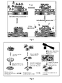
- Atomic Layer Deposition (see figure 1 ) consist in alternately reacting the precursors on the surfaces of the substrates and have the advantage of being the technique which leads to the highest coverage rates ( He M., et al., Nano Res., 2010, 4, 334-342 ).
- the temperature, the pressure, and the number of cycles also influence the ALD technique.
- a second method that is used to grow carbon nanotubes is the so-called chemical vapor deposition ("CVD") method.
- the substrate is exposed to one or more gas phase precursors, which react and / or decompose at the surface of the substrate to generate the desired deposit.
- CVD chemical vapor deposition
- a third method that can be considered is the method of vapor phase impregnation, which consists of saturating the surface of the substrate with the molecules to be grafted. This method is actually a variant of the CVD which is used when the substrate to be functionalized has a fibrous character.
- the invention has the technical problem of developing composite materials based on a polymer matrix and a reinforcing agent having both a very large specific surface area and properties intrinsic to carbon nanotubes which are better than the properties. carbon black.
- the stability of the composite materials by improving the interfacing between the polymer matrix and the reinforcing agent, will be increased.
- the use of carbon nanotubes solves the problem of including thermal, electrical and / or mechanical properties in such composite materials.
- the invention firstly relates to a composite material comprising at least one polymer matrix, said polymer matrix comprising at least one inorganic filler composed of a two-phase material.
- Said two-phase material comprises at least one mesoporous substrate at least partially covered with carbon nanotubes.
- the composite material of the present invention is notable in that said mesoporous substrate is a mesoporous substrate of unorganized porosity.
- said mesoporous substrate of unorganized porosity comprises diatomaceous silica, preferentially diatomite.
- the mesoporous substrate composition of unorganized porosity in said composite material is between 1% and 30%, preferably between 1% and 10%.
- the composition of the mesoporous substrate of unorganized porosity in said composite material is 1%, 2%, 3%, 4%, 5%, 6%, 7%, 8%, 9% or 10%. %, preferably 1%, 4% or 10%.
- said polymer matrix is composed of poly (methyl methacrylate) and / or at least one elastomer, said elastomer being preferably butadiene styrene rubber.
- the thermal degradation temperature of said composite material with a polymer matrix composed of poly (methyl methacrylate) increases by 25 ° C relative to the thermal degradation temperature of poly (methyl methacrylate).
- the Young's modulus of said composite material with a polymer matrix composed of butadiene styrene rubber increases between 50% and 300% relative to the Young's modulus of butadiene rubber styrene.
- the electrical conductivity of said composite material with a polymer matrix composed of butadiene styrene rubber and a diatomaceous composition of 10% is 2.5 ⁇ 10 -14 S.cm -1 .
- the subject of the invention is also a process for synthesizing a composite material.
- Said synthesis process comprises at least one extrusion step between at least one polymer matrix and at least one two-phase material.
- Said method of synthesis is remarkable in that said composite material is in accordance with the first object of the present invention.
- step (a) is carried out by impregnating the catalyst in the vapor phase, by chemical vapor deposition or by deposition of atomic layers and / or atomic particles, preferably by impregnation of the catalyst in the vapor phase.
- said catalyst is a metal nanoparticle supplied in a gaseous phase.
- said catalyst is a nickel derivative, preferably Ni (acac) 2 , or a cobalt derivative, preferably Co (acac) 2 .
- said catalyst is reduced by an alcohol derivative or by gaseous hydrogen.
- said alcohol derivative is a primary alcohol, preferably methanol, ethanol and / or propanol.
- said catalyst and said alcohol derivative are applied simultaneously when said step of supplying a catalyst on said at least one mesoporous substrate is carried out by chemical vapor deposition.
- said alcohol derivative is applied once said at least one catalyst is deposited on said at least one mesoporous substrate when said step of supplying a catalyst on said at least one mesoporous substrate is carried out by deposition. atomic layers and / or atomic particles.
- said gaseous hydrogen is mixed with nitrogen gas or another inert gas.
- said mixture between said hydrogen gas and said nitrogen gas comprises a portion of hydrogen gas which is between 2% and 30%, preferably between 10% and 20%.
- the step of reducing the catalyst with hydrogen gas is carried out for a duration of between 2 minutes and 30 minutes, preferably between 5 minutes and 20 minutes, more preferably between 10 minutes and 20 minutes, still more preferably for a period of 20 minutes.
- said at least one mesoporous substrate is composed of a silica derivative, preferably of diatomaceous silica or silicon, more preferably diatomaceous silica.
- said at least one derivative of silica is thermally oxidized at 1100 ° C. to provide a 50 nm thick layer of silicon dioxide, before said step of supplying a catalyst on said at least one mesoporous substrate.
- the Ni (acac) 2 is sublimed at a temperature between 150 ° C and 190 ° C, preferably at 180 ° C.
- the Co (acac) 2 is sublimated at a temperature between 150 ° C and 190 ° C, preferably at 170 ° C.
- said monotopic synthesis is carried out in a fluidized bed reactor.
- said growth step of carbon nanotubes comprises a growth step with acetylene gas, said acetylene gas being mixed with nitrogen gas, or another gas.
- said growth step of the carbon nanotubes is carried out at a pressure of between 2 mbar and 15 mbar, preferably at 13 mbar and at a temperature of between 500 ° C. and 800 ° C., preferably at a temperature of 500 ° C, 550 ° C, 600 ° C, 700 ° C or 800 ° C, more preferably at a temperature of 600 ° C.
- said step of growth of the nanotubes is carried out for a duration of between 3 minutes and 60 minutes, preferably for a time of 20 minutes, 40 minutes or 60 minutes, more preferably for a period of 40 minutes or 60 minutes, even more preferably for a period of 40 minutes.
- said mixture between acetylene gas and said nitrogen gas comprises a portion of acetylene gas relative to the nitrogen gas which is between 2% and 30%, preferably 10% or 20%. %, more preferably 20%.
- the invention is particularly interesting in that the composite material according to the present invention has interesting thermal, electrical and mechanical properties.
- Composite materials are indeed more thermally stable and have a high conductivity rate.
- mechanical properties it is necessary to notice the increase of the Young's modulus, as well as the values of the parameters of stress and strain at break of the composite materials according to the invention.
- the large surface area of the diatoms allows a stable attachment to the polymeric matrix as well as a high functionalization (by the CNTs) of this type of mesoporous substrate.
- the CNTs growth method on oxidized silicon substrates was developed.
- This process comprises the deposition of nanoparticles of Ni and Co by ALD / CVD / impregnation followed by a growth of nanotubes by CCVD.
- This process is then transferred to diatoms (3D substrate) through a fluidized bed. Integration of synthesized two-phase material into polymer matrices will be done using an extruder. The manufacture of specimens for physical characterization is done using an injection molding machine and a hydraulic press.
- the growth of carbon nanotubes requires a relevant choice of catalysts and their preparation techniques.
- the choice of the type of catalyst is constrained by the intended application.
- the Ni and Co have been selected because they do not have a negative impact on tire aging, unlike Fe.
- Diatoms are used as a mesoporous substrate of various complex forms (powders), all deposits do not allow to deposit nanoparticles on their surface.
- the atomic layer deposition technique (ALD has been chosen) is the most suitable for depositing materials on complex substrates. Impregnation in the vapor phase has also been experimented.
- Methanol, ethanol and propanol for the reduction of metal-organic precursors such as nickel acetylacetonate and cobalt acetylacetonate in ALD processes are used. This is the first time that alcohols are used in ALD as reducing agents to deposit Ni and Co layers (and their derivatives such as carbides).
- a TFS200 device from Beneq as a machine for ALD deposits was used.
- the flat substrates used consist of a silicon wafer covered with a layer of 50 nm of silicon oxide. This oxide layer well models the surface of diatoms and avoids the formation of alloys such as silicides between silicon and transition metals such as Ni and Co. This layer serves as a barrier to the diffusion of these metals in the silicon. Its growth is made by RTCVD (Rapid Thermal Chemical Vapor Deposition) at 1000 ° C on a silicon substrate oriented in the plane (100).
- RTCVD Rapid Thermal Chemical Vapor Deposition
- the samples (oxidized silicon) are first soaked in acetone under ultrasound for 10 minutes followed by rinsing with deionized water. The samples are then immersed in ethanol under ultrasound for 10 minutes and are then rinsed with deionized water. This cleaning makes it possible to eliminate organic contaminants and to form enough OH-hydroxyl groups on the surface of the thin layer of silica to react with the precursors during reactions caused by the ALD method.
- Organometallic precursors are used: nickel acetylacetonate and cobalt acetylacetonate, which are stable and inexpensive molecules, low in toxicity and easy to preserve.
- Nickel and cobalt acetylacetonate are purchased commercially (Sigma-Aldrich) as powders.
- the powders will then be loaded into a cane which will be introduced into the hot solid source.
- this source is heated to 170 ° C for nickel and 180 ° C for cobalt. These temperatures make it possible to evaporate a large quantity of material without breaking it down.
- the steam will be transported to the reaction chamber by a stream of nitrogen.
- Methanol, ethanol and propanol are used herein as reagents for the reduction of nickel acetylacetonate and cobalt acetylacetonate vapors already adsorbed on the surface of the substrate. These 99% pure alcohols are purchased commercially (Sigma-Aldrich).
- Dehydrogenation of alcohols is a process that has been put in place for the production of aldehydes and ketones.
- the ability of alcohols to undergo dehydrogenation strongly depends on their structure and temperature. This process is also catalyzed by transition metals or by transition metal complexes.
- the reaction mechanism is described as follows: -OH groups on the surface of the sample are partially ionized.
- M (acac) 2 on the surface of the silicon oxide is made possible by the fact that these -OH groups have accepted the axial ligand of M (II).
- the formation of an acetylacetone molecule is due to the strong interactions between the protons of the surface -OH groups and the electron system of the acetylacetonate ligands.
- the adsorbed M (acac) is then reduced by hydrogen atoms following an interaction with the alcohol.
- a protocol with the deposition parameters in the form of a sequential computer program is used. This program controls the opening of the valves for each pulse and purge, the heating temperatures and times of the reaction chamber and the hot sources, the carrier gas flows, the number of cycles and the pulse times for each precursor.
- the deposition temperature was varied between 200 and 390 ° C.
- the pulse and purge times ranged from 0.1 to 4s and the final choice depended on the growth rate and morphology targeted for the films.
- the carrier gas flows are set at 300 sccm, sufficient to transport the precursors to the reactor.
- the number of ALD cycles has been varied from 100 to 4000 depending on the film thickness or the morphologies to be obtained.
- the growth of CNTs is initially carried out on planar substrates (oxidized silicon) in order to determine the optimum value of the growth parameters. Then in a second time, this growth is performed on diatoms in 3D configuration.
- the Catalytic Chemical Deposition (CCVD) method is used in an MC200 device manufactured by Annealsys to treat flat substrates.
- a fluidized-bed reactor is used for the growth of CNTs on diatoms.
- the Annealsys MC200 machine is a Metal Oxide Chemical Vapor Deposition (MOCVD) reactor with controlled wall temperature.
- MOCVD Metal Oxide Chemical Vapor Deposition
- the diatoms are in the form of particle powders between 1 and 10 microns in diameter.
- the growth of carbon nanotubes on the latter can not therefore be done in a planar configuration but in a fluidized bed reactor.
- the present invention is concerned with the development of composites based on these two-phase materials.
- the next step is to integrate it into a polymer matrix.
- a mixing technique which ensures a good dispersion of the reinforcing agents in the matrix without damaging them (shearing of CNTs and separation of their silicon support). Both materials are mixed by extrusion.
- a microextruder is used to mix the polymers and fillers, and an injection molding machine for the production of test specimens.
- a micro-extruder model "DSM Xplore" micro 15, double-screw, with a 15 mL capacity chamber with 6 heating zones (with a maximum temperature of 350 ° C) is used.
- the rotational speed of the worm is adjustable and can vary from 1 to 250 rpm. Cooling is done with a water circuit. At the extruder outlet, a rod 3 mm in diameter is obtained.
- the heating temperature and the speed of rotation of the screws are first adjusted.
- the temperature is set so that it coincides with the melting temperature of the polymer (180 ° C for PMMA).
- the rotational speed of the screws (which rotate in the mixing chamber) is fixed and, depending on the density of the polymer and the loads, the shear force is automatically calculated by the apparatus. It is then necessary to weigh the products to mix (the polymer and the load) since they are solid and to introduce them in small quantities through the injector.
- the mixture is made inside the chamber for a time sufficient for the products (5 minutes) to homogenize.
- the ring is recovered at the end of the mixture.
- the product obtained is shaped in order to make test pieces for mechanical and electrical analyzes.
- an injection molding machine is used for shaping.
- a "Thermo Scientific HAAKE Minijet II" injection molding machine measuring 300mm x 460mm x 710mm is used.
- the injection is done using a piston with a maximum pressure of 1200 bar, the air pressure can go up to 10 bar.
- Several molds of different shapes can be used to perform several types of samples; the molds can be heated up to 250 ° C. The pressure and the duration of the injection are chosen to ensure the reproducibility of the samples.
- the materials to be injected are first introduced and are melted in a cylinder which can be heated up to 400 ° C. This cylinder is placed above the mold. The piston applies pressure to the cylinder to push its container to the mold to be filled.
- the SEM is perfectly suited to the observation of the morphologies of thin films, catalyst particles and also carbon nanotubes. This technique provides information on the density, the size of the nanoparticles and carbon nanotubes, making it possible to image structures of size up to 10 nm. The SEM also provides information on the dispersion of nanotubes in the polymer matrix, which is crucial for understanding the physical properties of the composite.
- the MET Due to its high spatial resolution, the MET provides access to information of the atomic order. It makes it possible to distinguish the single wall or multiwall nanotubes and to see the defects that are on the tubes. With the MET, it is possible to distinguish the following structures: nanotubes, fibers, bamboo structure ... This imagery also makes it possible to evaluate how the nanotubes are dispersed in the PMMA.
- the MET analyzes were made with a 'LEO 922 OMEGA' equipped with a field emission gun with an acceleration voltage of up to 200 kV, EELS detectors (electron energy loss spectrometer) , X-rays, SE (secondary electron), and BSE (retro-diffused electrons). The resolution of the instrument is 0.29 nm.
- the composite samples (PMMA + biphasic) were cut into thin slices of thickness varying between 70-100 nm by a microtome.
- the samples in the form of powders were directly deposited on the TEM grid.
- XPS X-ray photoelectron spectroscopy
- XPS is a surface chemical analysis technique with which the sample is irradiated with monochromatic x-rays. These, by photoelectric effect, cause the ionization of atoms. This allows access to information such as the chemical composition of materials (thin layers).
- the XPS is perfectly suited for the chemical composition of the catalyst nanoparticles and thin metal films that have been used for the catalysis of the growth of carbon nanotubes.
- the instrument has a spatial resolution of 10 ⁇ m (spectroscopy) and 3 ⁇ m (imaging); the sensitivity limit is 0.5.
- the link energies are calibrated on the carbon bonding energy 1s.
- the mechanical properties are studied through the tensile tests on the specimens manufactured by injection. These tensile tests provide the evolution of the stress as a function of the deformation.
- the mechanical behavior of the material is manifested by the properties of the stress-strain curve, which allows to extract the tensile strength, the elastic limit and the maximum deformation (elongation) of the material before fracture. This curve also makes it possible to determine three domains corresponding to the zone of elasticity, the zone of plastic deformation and the rupture zone of the material.
- Thermogravimetric analysis is often used to determine the characteristics of materials that are related to their a loss of mass. This loss of mass is due to the decomposition, the oxidation ... of the components of the material under the effect of the temperature. TGA has been used to investigate the thermal stability of composites through their loss of mass.
- the device used is a NETZSCH-STA 409 PC, with a flow of air of 100 cm 3 .min -1 in an aluminum crucible containing 20-25 mg of the sample. The measurements were made under dynamic conditions with a temperature ramp of 10 ° C.min -1 .
- Ni (acac) 2 and Co (acac) 2 reduced by alcohols are used on silicon oxide substrates. This process was previously developed in CVD [113] but was developed for the first time in ALD. The growth of carbon nanotubes by CVD on catalytic nanoparticles prepared by ALD, CVD and vapor phase impregnation is then presented.
- the growth of carbon nanotubes is catalyzed by cobalt and nickel nanoparticles prepared by the ALD technique.
- Ni (acac) 2 is in powder form and sublimed at 180 ° C; as for the alcohols they were evaporated at room temperature.
- the purge of the reactor is provided by a continuous nitrogen flow of 300 sccm.
- An ALD cycle comprises a pulse of Ni (acac) 2 (pulse time Ni ) and an alcohol pulse (pulse and alcohol time ) separated by a purge of the reactor (purge time t P ).
- the purge time is set at 2s and the pulse time of Ni (acac) 2 and alcohols vary between 0.1 and 4s.
- the deposition temperature varies between 200 and 300 ° C.
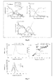
- the figure 3 shows the increase in the growth rate of the films (defined here in ng / cm 2 / cycle) as a function of the injection time of alcohols (t alcohol ) for the three alcohols of increasing alkyl chain length.
- This increase has already been observed by Premkumar and his collaborators in the context of a CVD process using Co (acac) 2 as a precursor (Premkumar PA, et al., Chem., Vap Depos., 2007, 13 , 219-226). .
- This is attributed to the incomplete dissociation of the alcohol during the process leading to incorporation of the carbon into the film and consequently to the increase of the mass of the film.
- the increase in the amount of carbon is correlated with that of the growth rate obtained using ethanol and propanol relative to methanol.
- Dehydrogenation of primary alcohols has been shown to provide hydrogen, CO, CO 2 , aldehydes and other fragments from their decomposition.
- the use of methanol which has only one carbon atom in its structure is therefore favorable to reduce the contamination of the carbon film and then allows to obtain the growth of a nickel metal film.
- Carbon is the main element present on the surface of the film formed with methanol as reducing agent but then in the core of the film, nickel becomes the major element until the silica layer is reached.
- carbon is the dominant element on the surface and in the film, up to the silica layer.
- the XPS spectra of the carbon and nickel core levels are shown on the figure 5 .
- the fine structure of the peak Ni2p core level shows that this element is in the form of reduced nickel (metal) for all films.
- Ni 2p3 / 2 in its metallic phase has been reported at 852.8 eV and is different from that of its oxide phases (854.6 eV for NiO, 855.7 eV for Ni 2 O 3 and 856.45 eV for Ni (OH) 2 ).
- the XPS spectrum of Ni 2p3 / 2 in its metallic phase has a satellite peak at +6 eV that has been attributed to plasmon energy losses and inter-band transitions.
- This satellite peak is found on the Ni 2p spectrum of the deposited film using methanol as a reducing agent ( Figure 5 insert). With ethanol or propanol, the satellite peaks are shifted by 1 eV towards the higher binding energies. This effect was also observed on a composite of nickel carbide and carbon deposited by a sputtering process.
- the figure 6 shows the XPS analyzes of films deposited from Co (acac) 2 and the three alcohols as reducing agents. Unlike nickel films, carbon is present in all films with a concentration greater than 50%. The concentration of cobalt increases with the alcohol used: 25% with methanol, 40% with ethanol and 50% with propanol. None of the alcohols used reduces the Co (acac) 2 completely until a purely metallic film is obtained. The films deposited with propanol were selected to study the crystalline structure of the thickest deposits.
- the figure 7 shows the C 1s and Co 2p spectra of films deposited at 350 ° C before and after ionic bombardment of the surface.
- the intensity of the C 1s carbon peak at the surface of the film (0s bombardment time) is higher than that in the film (300s bombardment time) due to surface air contamination.
- the maximum and peak shape are respectively shifted and expanded after 300s of bombardment.
- spectral decomposition using a mixed Gaussian-Lorentzian function the presence of two contributions at 284.4 and 283.5 eV is demonstrated ( Figure 7b ). These correspond respectively to the links CC and C-Co. This indicates that a fraction of the carbon contained in the film is bonded with cobalt to form a carbide phase.
- the binding energies of Co 2p3 / 2 and Co 2p1 / 2 ( Figure 7c ) after 300s of bombardment are measured at 778.4 and 793.4 eV and correspond to the metallic phase of cobalt.
- two shoulders are measured at 780.8 and 796.8 eV associated with their respective satellites at 787.7 and 804.2 eV and correspond to a phase of cobalt oxide.
- ALD of methanol reduced Ni (acac) 2 can result in a phase of Ni metal and Ni carbide when it is reduced by ethanol and propanol.
- the reaction of Co (acac) 2 with the three alcohols systematically produces cobalt carbide, including with methanol.
- This cobalt carbide phase is not, however, unacceptable for its use as a growth catalyst for carbon nanotubes.
- the growth process of CNTs uses a step of reduction to hydrogen preliminary to growth for the activation of metal or carbon catalysts.
- the figure 8 shows the growth procedure of carbon nanotubes on a plane substrate.
- Nickel layers deposited from methanol reduced Ni (acac) 2 and Ni carbide layers from ethanol reduced Ni (acac) 2 were used.
- unsaturation conditions to result in nanoparticles well separated on the surface of the substrate and saturation conditions for depositing a film that well covers the surface of the substrate were used.
- the utilization parameters are as follows: 1s of pulse time Ni (acac) 2 , 1s of alcohol pulse time, 2s of purge and 1000 cycles at 300 ° C.
- the utilization parameters are as follows: 2s pulse time Ni (acac) 2 , 2s pulse time alcohols, 2s purge and 3000 cycles ( ⁇ 30nm for ethanol, -15 nm for methanol).
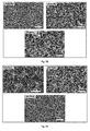
- the figure 9 shows the different morphologies of the deposits according to the saturation parameters.
- the Ni-Meth 1000 cycle shows smaller particles compared to the Ni-Eth-1000 cycles, the nickel deposits from the Ni (acac) 2 reduced by methanol have lower growth rate.
- the thickness of the Ni-Eth-3000 cycle film is therefore higher than that of Ni-Meth-3000 cycles.
- the pressure in the reaction chamber is 13 mbar.
- the growth was made on nickel nanoparticles deposited by ALD at 1000 and 3000 cycles.
- nanotube synthesis tests performed on the particles deposited at 1000 cycles at 500 and 700 ° C were not successful. On the samples deposited at 3000 cycles, tortuous structures were obtained as previously at 500 ° C. On the other hand at 700 ° C., nanotubes were obtained but with a low surface density compared to the nanotube mats which are obtained with cobalt.
- ALD of Ni (acac) 2 and ethanol has been shown to yield nickel carbide.
- Ni (acac) 2 and ethanol has been shown to yield nickel carbide.
- some structures (certainly fibers) at the surface were observed.
- By cons at 700 ° C there is no growth apart from a few long structures on the surface.
- the figure 11 shows different types of cobalt films deposited by three different processes: CVD, ALD and vapor phase impregnation.
- the CVD deposits were made from a solution of Co (acac) 2 and ethanol.
- Co (acac) 2 powder is dissolved in ethanol to make a solution at 5 mmol.L -1 . This solution is thus injected for 10 or 40 minutes on a silicon oxide substrate heated to 300 ° C.
- the ALD deposits were made by reacting Co (acac) 2 and ethanol with 1s of Co (acac) injection time 2 , 2s of ethanol injection time, 2s of purging time. 1000 cycles and 4000 cycles were used.
- the vapor phase impregnation consists in injecting for 150s the sublimated Co (acac) 2 vapor at 155 ° C.
- figure 11 shows the presence of such nanoparticles for the ALD sample made at 1000 cycles (4 to 8 nm in diameter on average), and that made at 4000 cycles (between 6-8 nm in average diameter).
- Nanotube growth on particles deposited by CVD Nanotube growth on particles deposited by CVD.
- the total pressure in the reaction chamber is 13 mbar.
- the growth temperature is varied from 500 to 800 ° C.
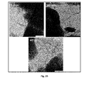
- the figures 12 and 13 show TEM images of samples synthesized at 500 ° C and 700 ° C, respectively.
- the figure 12 reveals carbon fiber type structures of large diameter ( ⁇ 80 nm) and typical length ⁇ 150 nm.
- the Co nanoparticle (clearly observed on the left panel 18) catalyzes a "tip-growth" growth of carbon fibers.
- the growth regime of CNTs requires minimum temperatures of the order of 700 ° C as confirmed by the photographs of the figure 13 . For this temperature, the characteristic structures of single- and double-walled carbon nanotubes are highlighted. Their diameter varies between 1 and 3 nm with some structural defects especially observed on double-walled nanotubes.
- Nanotube growth on particles deposited by vapor phase impregnation Nanotube growth on particles deposited by vapor phase impregnation.
- the figure 14 shows SEM images of nanotubes synthesized at different temperatures on substrates impregnated with Co (acac) 2 vapor sublimed at 170 ° C.
- the pressure in the reaction chamber is 13 mbar.
- the temperature is varied from 500 to 800 ° C.
- the figure 15 shows the morphology of the nanotubes obtained at 700 ° C. The presence of single wall nanotube bundles that appear well crystallized and without too much amorphous carbonaceous particles or deposits or onions is observed.
- Nanotube growth on particles deposited by ALD Nanotube growth on particles deposited by ALD.
- the figure 16 shows SEM images of carbon nanotubes synthesized at 500 and 700 ° C. As previously, at 500 ° C, the presence of fibrous structures is suspected. On the other hand at 700 ° C., a dense carpet of nanotubes covering the entire surface of the sample is obtained.
- the MET images presented at figure 17 confirm the suspected fibrous structures on the sample synthesized at 500 ° C.
- the nanotube mat corresponds to multi-wall CNTs with a few defects on the outer walls and with a diameter of between 15 and 20 nm.
- the growth mode is of the "top-growth" type.
- a mixture of single- and double-walled nanotubes from 600 ° C is obtained with CVD samples.
- the growth of carbon nanotubes on the samples made by impregnation results in bundles of single-walled tubes and some double-walled tubes.
- the sample made by ALD 4000 cycles (average particle size around 8 nm) meanwhile provides a carpet of "high" type multi-walled nanotubes.
- the sample made at 1000 cycles of ALD gives the same structures as those observed on the CVD at 700 ° C, single or double wall nanotubes, which correlates well the influence of the particle size which is about 4 to 8 nm of average diameter. Moreover, the sample at 4000 cycles gives a carpet of multi-walled tubes as observed at the figure 18 .
- the figure 19 shows that after 3 minutes of growth (constant parameter), a mat of nanotubes is already formed.
- the carpet becomes more and more dense with increasing growth time.
- the hydrogen reduction time preceding the growth step was investigated here keeping all parameters constant.
- the figure 20 shows SEM images of nanotubes synthesized at 0, 10 and 20 minute reduction times. Without a reduction step, a low density of nanotubes on the surface of the sample is noticed. By cons for 10 and 20 minutes, a multi-walled nanotube mat is generated.
- the role of hydrogen reduction is to clean the surface of the particles and to reduce the oxidized particles. In the absence of hydrogen, the oxidized particles and those contaminated on the surface are not activated, which leads to a very low density of nanotubes.
- the figure 21 shows SEM images of nanotubes synthesized at different concentrations of acetylene keeping the same conditions as before. A concentration of 2%, 10% and 30% acetylene in nitrogen was used, and it was observed that this concentration significantly influences the surface density of the nanotubes. At 2%, the process provides a much lower density than 10%. Under these conditions, there are not enough carbon atoms to react with the particles. It has also been shown that at low concentration of the precursor, the available carbon content reacting with the catalytic particles is low, leading to low growth.
- a low density of nanotubes is also obtained: at a high concentration of acetylene, the concentration of available carbon atoms becomes very high, the dissolution rate becomes high compared to the rate of precipitation and the rate of diffusion. This causes carbon accumulation on the surface of the particle and accelerates its supersaturation and loss of catalytic activity, which leads to a low density of nanotubes.
- the cobalt carbide particles were deposited on diatoms by ALD in internal fluidized-bed configuration.
- the precursor used is cobalt acetylacetonate, and the reducing alcohol is ethanol.
- the figure 22 shows the SEM images of deposits made at 250, 300 and 350 ° C.
- the exposure time of the precursors was 20s each and the purge time, the number of cycles was 115. No deposit was observed at 250 ° C, this is only from 300 ° C that the growth of nanoparticles of cobalt carbide on the surface of diatoms is observed.
- the activation energy When grown by ALD, the activation energy must be sufficient to allow the growth of the first atomic layers.
- the role of the temperature is thus to allow the activation of the adsorption of the precursors on the surface of the substrate and the reaction between the two precursors.
- the rise in temperature promotes the surface migration of cobalt atoms and leads to the formation of films or nanoparticles.
- FIG. figure 23 The morphology of the deposits made at 300 ° C. by varying the number of cycles is illustrated in FIG. figure 23 . At 115 cycles, less dense and well-dispersed particles are observed. The figure 23 also reports the particle size distribution according to the number of cycles obtained after extraction and processing of SEM images by the Gwyddion software. From 115 to 600 cycles of ALD, there is a slight increase in the average particle size. This is in accordance with the results reported in the literature which show that in ALD processes the particle size increases with the cycle number and hence the thickness of the films.
- the size and density of the catalytic particles will be parameters that greatly influence the size and density of carbon nanotubes. These two characteristics of the catalyst can be controlled from the parameters of the ALD process.
- the figure 24 shows MET images of tubes formed at different temperatures. At 500 ° C, the images show short and tortuous structures. At 600 ° C., the sample consists essentially of multiwall nanotubes with numerous defects inducing large bends. At 700 ° C, a mixture of nanotubes mono-paroid small diameter and multi-wall is observed. The sample synthesized at 800 ° C also shows single-walled and multi-walled nanotubes of larger diameter compared to those of the sample at 700 ° C.
- the influence of the growth time was studied at a temperature of 600 ° C., with a reduction time of 20 minutes under hydrogen, a growth using a mixture of 20% hydrogen in N 2 and 20 % acetylene in N 2 .
- the figure 25 shows MET images of the morphology of nanotubes at 5, 20 and 40 minutes of growth. At 5 minutes of growth, the tubes are relatively short compared to those synthesized at 20 minutes and 40 minutes. The number of nanotubes seems to be greater at 40 minutes of growth, but this does not confirm that diatoms are 3D structures and TEM images are only a 2D projection. Several authors have shown that the density and length of nanotubes increase with increasing growth time.
- FIG. 26 Three concentrations of acetylene (5, 20 and 40%) in N 2 .
- the figure 26 shows the MET images of the nanotube morphology as a function of this concentration. At 5% acetylene, a very low growth rate is noticed and there are very few nanotubes. MWNT tubes on the 20 and 40% samples are observed. The increase in the concentration of the carbon source therefore favors the growth of MWNT.
- the temperature at 600 ° C., the growth time at 20 minutes, the concentration of acetylene at 20 mol% in N 2 , the reduction time with hydrogen is varied at 0.5. and 20 minutes to study its influence on the morphology of nanotubes.
- the TEM images presented at figure 27 show MWNTs. Black spots on CNTs without hydrogen reduction are observed. It is certainly metal particles. At 20 minutes, the nanotubes have few defects and seem to be less polluted by these particles.
- the Co (acac) 2 is heated to 170 ° C (evaporation temperature), then a nitrogen stream of 200 sccm is introduced to transport the Co (acac) vapor on the diatom particles suspended (fluidization) for 10 minutes. Then, the reduction step is carried out by introducing 20% dilute hydrogen in nitrogen at 600 ° C for 20 minutes. Then, the acetylene, also diluted to 20% in nitrogen, is introduced for 40 minutes.
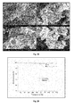
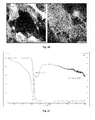
- the figure 28 shows SEM images of CNTs synthesized on diatoms with previously selected parameters. A high density of CNTs on some diatoms and low density on others is noticed. The coverage rate is not 100%. Some diatoms may not have been sufficiently exposed to precursor gases.
- the figure 29 shows the thermogravimetric analysis of the sample presented at figure 28 .
- Mass loss was measured in a NETZSCH-STA 409 PC, with an air flow of 100 cm 3 ⁇ min -1 in an aluminum crucible containing 20-25 mg of the sample. The measurements were made under dynamic conditions with a temperature ramp of 10 ° C.min -1 .
- the nanotubes (and probably the deposit of carbon residues) are completely oxidized, which makes it possible to approximate the rate of coverage to 6% by weight with respect to diatoms.
- the two-phase materials based on silica (diatoms) and carbon nanotubes in accordance with the present invention are used in particular as reinforcement agents in composite materials based on polymers, more particularly based on elastomers.
- These reinforcing agents have remarkable properties, in particular the increase in the specific surface area of silica-based material due to the introduction of carbon nanotubes, the provision of electrical and / or thermal properties to silica-based materials. .
- PMMA polymethyl methacrylate
- SBR styrene-butadiene type elastomer
- Nanocomposites based on PMMA and biphasic charges are described.
- the mechanical and thermal properties of the composite based on PMMA and two-phase are studied.
- the mixtures were made at a temperature of 180 ° C (sufficient to melt PMMA) and at a rotation speed of 10 rpm, to avoid detaching the tubes from diatoms.
- the figure 30 shows the PMMA composite PMMA images loaded at 10% by mass of two-phase obtained at 10 rpm speed of rotation of the screws of the extruder. Nanotubes form a continuous and uniform network around diatom cores. Nevertheless, the speed 10 rpm seems sufficiently important to "tear" some nanotubes isolated diatoms.
- the two-phase diatom / CNT charges are homogeneously dispersed in the PMMA matrix, with a high concentration of nanotubes around the diatom cores.
- the figure 31 also indicates DTA (thermodifferential analysis) of PMMA, with endothermic behavior of the thermal decomposition of PMMA in an inert atmosphere. This behavior is associated with the depolymerization of the main chain by the random breaking of CC bonds and the formation of volatile methyl methacrylate monomers.
- DTA thermodifferential analysis
- Diatoms have a catalytic effect accelerating the thermal degradation of the composite and reducing its thermal stability compared to PMMA alone.
- Nanotubes have the opposite effect, they tend to increase the thermal stability of the composite and can even offset the diatom effect at 10% reinforcement when using two-phase loads. At low levels of reinforcement, the effect of diatoms prevails over nanotubes ( figure 34 ).
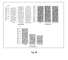
- the elastic modulus ( figure 36 ) increased from 2639 (+/- 13) MPa for PMMA to 2793 (+/- 10) by adding 4% diatom to PMMA, an increase of 6%. At 10% diatom, there is an increase of 11% more.
- the tensile strength Rm does not change compared to that of PMMA at 4% and 10%.
- the decrease in elongation is observed from 0.06 (+/- 0.003) for PMMA to 0.037 (+/- 0.001) to 4% diatomaceous and 0.033 (+/- 0.001) to 10% diatom.
- Nanocomposites based on SBR and biphasic charges (diatom + carbon nanotubes).
- Vulcanizing agents such as cyclohexyl-benzothiazyl sulphonamide (CBS), zinc dibenzyl-dithiocarbamate (ZBec) which accelerate the vulcanization, and the main vulcanizing agent, sulfur (S) were then added.
- CBS cyclohexyl-benzothiazyl sulphonamide
- ZBec zinc dibenzyl-dithiocarbamate
- S main vulcanizing agent
- test pieces The dimensions of the test pieces are: 65 mm x 10 mm x 3 mm.
- diatoms in the SBR slightly decreases the thermal stability of the elastomer as shown in FIG. figure 39 .
- 1% of diatoms causes a shift of -24 ° C; at 4%, the offset is -13 ° C and -14 ° C to 10% diatom.
- the Figures 41 and 42 show the stress-strain curves obtained after tensile tests on SBR alone and SBR reinforced at 1, 4 and 10% by mass of diatoms and 1, 4 and 10% of two-phase (diatom + carbon nanotubes).
- diatoms significantly increases the Young's modulus and the tensile strength of the SBR but decreases the elongation with respect to the SBR. Diatoms form a good interface with SBR molecules.
- CNTs significantly improve the interfacing between diatoms and the matrix.
Landscapes
- Chemical & Material Sciences (AREA)
- Organic Chemistry (AREA)
- Engineering & Computer Science (AREA)
- Materials Engineering (AREA)
- Nanotechnology (AREA)
- Chemical Kinetics & Catalysis (AREA)
- Inorganic Chemistry (AREA)
- Polymers & Plastics (AREA)
- Medicinal Chemistry (AREA)
- Health & Medical Sciences (AREA)
- Mechanical Engineering (AREA)
- Physics & Mathematics (AREA)
- Dispersion Chemistry (AREA)
- Spectroscopy & Molecular Physics (AREA)
- Carbon And Carbon Compounds (AREA)
Priority Applications (5)
| Application Number | Priority Date | Filing Date | Title |
|---|---|---|---|
| PT151737210T PT3109202T (pt) | 2015-06-24 | 2015-06-24 | Elemento compósito que compreende material bifásico à base de sílica e de nanotubos de carbono |
| SI201531672T SI3109202T1 (sl) | 2015-06-24 | 2015-06-24 | Kompozitni element, obsegajoč dvofazen material na osnovi silicijevega dioksida in karbonskih nano-cevk |
| EP15173721.0A EP3109202B1 (de) | 2015-06-24 | 2015-06-24 | Verbundelement, das ein biphasenmaterial auf bais von siliciumdioxid und kohlenstoffnanoröhren umfasst |
| US15/739,266 US10988620B2 (en) | 2015-06-24 | 2016-06-21 | Composite element comprising a biphasic silica and carbon nanotube-based material |
| PCT/EP2016/064244 WO2016207129A1 (fr) | 2015-06-24 | 2016-06-21 | Elément composite comprenant un matériau biphasique à base de silice et de nanotubes de carbone |
Applications Claiming Priority (1)
| Application Number | Priority Date | Filing Date | Title |
|---|---|---|---|
| EP15173721.0A EP3109202B1 (de) | 2015-06-24 | 2015-06-24 | Verbundelement, das ein biphasenmaterial auf bais von siliciumdioxid und kohlenstoffnanoröhren umfasst |
Publications (2)
| Publication Number | Publication Date |
|---|---|
| EP3109202A1 true EP3109202A1 (de) | 2016-12-28 |
| EP3109202B1 EP3109202B1 (de) | 2021-05-26 |
Family
ID=53498812
Family Applications (1)
| Application Number | Title | Priority Date | Filing Date |
|---|---|---|---|
| EP15173721.0A Active EP3109202B1 (de) | 2015-06-24 | 2015-06-24 | Verbundelement, das ein biphasenmaterial auf bais von siliciumdioxid und kohlenstoffnanoröhren umfasst |
Country Status (5)
| Country | Link |
|---|---|
| US (1) | US10988620B2 (de) |
| EP (1) | EP3109202B1 (de) |
| PT (1) | PT3109202T (de) |
| SI (1) | SI3109202T1 (de) |
| WO (1) | WO2016207129A1 (de) |
Families Citing this family (4)
| Publication number | Priority date | Publication date | Assignee | Title |
|---|---|---|---|---|
| EP3109201A1 (de) * | 2015-06-24 | 2016-12-28 | Luxembourg Institute of Science and Technology (LIST) | Zweiphasenmaterial auf der basis von siliciumdioxid und kohlenstoffnanoröhren |
| US10791651B2 (en) * | 2016-05-31 | 2020-09-29 | Carbice Corporation | Carbon nanotube-based thermal interface materials and methods of making and using thereof |
| TWI755492B (zh) | 2017-03-06 | 2022-02-21 | 美商卡爾拜斯有限公司 | 基於碳納米管的熱界面材料及其製造和使用方法 |
| CN109092245B (zh) * | 2018-08-24 | 2020-12-22 | 华南理工大学 | 一种硅藻土负载碳纳米管吸附剂及其制备方法 |
Family Cites Families (3)
| Publication number | Priority date | Publication date | Assignee | Title |
|---|---|---|---|---|
| US7816709B2 (en) * | 1999-06-02 | 2010-10-19 | The Board Of Regents Of The University Of Oklahoma | Single-walled carbon nanotube-ceramic composites and methods of use |
| AUPR421701A0 (en) * | 2001-04-04 | 2001-05-17 | Commonwealth Scientific And Industrial Research Organisation | Process and apparatus for the production of carbon nanotubes |
| JP6004528B2 (ja) * | 2011-08-29 | 2016-10-12 | 地方独立行政法人東京都立産業技術研究センター | 多孔質シリカ内包粒子の製造方法および多孔質シリカ |
-
2015
- 2015-06-24 SI SI201531672T patent/SI3109202T1/sl unknown
- 2015-06-24 EP EP15173721.0A patent/EP3109202B1/de active Active
- 2015-06-24 PT PT151737210T patent/PT3109202T/pt unknown
-
2016
- 2016-06-21 US US15/739,266 patent/US10988620B2/en not_active Expired - Fee Related
- 2016-06-21 WO PCT/EP2016/064244 patent/WO2016207129A1/fr not_active Ceased
Non-Patent Citations (15)
| Title |
|---|
| ABRASONIS G. ET AL., X-RAY SPECTROSCOPIC AND MAGNETIC INVESTIGATION OF C, vol. 112, 2008, pages 12628 - 12367 |
| COSTACHE M.C. ET AL., POLYM. ADV. TECHNOL., vol. 7, 2006, pages 272 - 280 |
| DURAIA E. M. ET AL., VACUUM, vol. 84, 2010, pages 464 - 468 |
| HE M., NANO RES., vol. 4, 2010, pages 334 - 342 |
| LI CHUNHUA: "SCIENCE IN CHINA (Series E) Synthesis of carbon nanotubes with Ni/CNTs catalyst", XU CAILU () & WU DEHAI (3ǷǷ), 30 June 2003 (2003-06-30), XP055231947, Retrieved from the Internet <URL:http://tech.scichina.com:8082/sciEe/fileup/PDF/03ye0303.pdf> [retrieved on 20151127] * |
| MATHUR R. B. ET AL., POLYM. COMPOS., vol. 29, 2008, pages 717 - 727 |
| PANDE S. ET AL., POLYM. COMPOS., vol. 30, 2009, pages 1312 - 1317 |
| PREMKUMAR P. A. ET AL., CHEM. VAP. DEPOS., vol. 13, 2007, pages 219 - 226 |
| PREMKUMAR P. A., CHEM. MATER., vol. 19, 2007, pages 6206 - 6211 |
| SOLANKI R ET AL: "Atomic layer deposition of copper seed layers", ELECTROCHEMICAL AND SOLID-STATE LETTERS, IEEE SERVICE CENTER, PISCATAWAY, NJ, US, vol. 3, no. 10, 1 October 2000 (2000-10-01), pages 479 - 480, XP002254875, ISSN: 1099-0062, DOI: 10.1149/1.1391185 * |
| TROITSKII B. B, INHIBITION OF THERMO-OXIDATIVE DEGRADATION OF PMMA AND POLYSTYRENE BY C 60, vol. 36, 2000, pages 1073 - 1084 |
| WANG HONG ET AL: "Catalysts for chirality selective synthesis of single-walled carbon nanotubes", CARBON, ELSEVIER, OXFORD, GB, vol. 81, 28 September 2014 (2014-09-28), pages 1 - 19, XP029093003, ISSN: 0008-6223, DOI: 10.1016/J.CARBON.2014.09.063 * |
| WEI-DE ZHANG ET AL: "Polymer Nanocomposites Using Urchin-Shaped Carbon Nanotube-Silica Hybrids as Reinforcing Fillers", MACROMOLECULAR RAPID COMMUNICATIONS, vol. 25, no. 21, 3 November 2004 (2004-11-03), DE, pages 1860 - 1864, XP055232043, ISSN: 1022-1336, DOI: 10.1002/marc.200400352 * |
| ZHANG W.D., MACROMOL. RAPID COMMUN., vol. 25, 2004, pages 1860 - 1864 |
| ZHAO J., COMPOSITES: PARTA, vol. 58, 2014, pages 1 - 6 |
Also Published As
| Publication number | Publication date |
|---|---|
| WO2016207129A1 (fr) | 2016-12-29 |
| SI3109202T1 (sl) | 2021-11-30 |
| US20180187020A1 (en) | 2018-07-05 |
| US10988620B2 (en) | 2021-04-27 |
| EP3109202B1 (de) | 2021-05-26 |
| PT3109202T (pt) | 2021-08-30 |
Similar Documents
| Publication | Publication Date | Title |
|---|---|---|
| EP3109202B1 (de) | Verbundelement, das ein biphasenmaterial auf bais von siliciumdioxid und kohlenstoffnanoröhren umfasst | |
| EP2254830B1 (de) | Wachstum von kohlenstoffnanoröhren auf kohlenstoff- oder metallsubstraten | |
| EP1663864B1 (de) | Auf polymer basierende verbundwerkstoffe mit kohlenstoffnanoröhren als füllstoff, herstellungsverfahren dafür und verwendungen davon | |
| CN102007236B (zh) | 碳纳米纤维及其制备方法、使用了碳纳米纤维的碳纤维复合材料的制备方法以及碳纤维复合材料 | |
| JP5650650B2 (ja) | ポリマー膜でコーティングされた炭素粒子、その製造方法およびその使用 | |
| EP2370355B1 (de) | Verfahren zur synthese von kohlenstoffnanoröhren auf langen teilchenförmigen mikrometrischen materialien | |
| EP2097168A2 (de) | Verfahren zur herstellung von kohlenstofffibrillen und/oder -nanoröhrchen aus einer katalysatorintegrierten kohlenstoffquelle | |
| EP1713959A2 (de) | Verfahren zur herstellung von kohlenstoffnanoröhren auf trägern und verbundwerkstoffe damit | |
| Ashcroft et al. | Functionalization of individual ultra-short single-walled carbon nanotubes | |
| EP2144698A2 (de) | Komposit aus nanoröhrchen oder nanofasern auf einem b-sic-film | |
| Kushkina et al. | Evolution of the multi-walled carbon nanotubes structure with increasing fluence of He ion irradiation | |
| CN106044855A (zh) | 一种制备单层MoS2的新方法 | |
| EP3109201A1 (de) | Zweiphasenmaterial auf der basis von siliciumdioxid und kohlenstoffnanoröhren | |
| FR3063721A1 (fr) | Nanotubes de carbone dopes au soufre et leur procede de preparation | |
| EP3645461B1 (de) | Verfahren zur herstellung von kabeln, die aus ausgerichteten kohlenstoffnanoröhrchen gefertigt sind | |
| Pereira et al. | CH and CN Radical Contribution in the Particle Formation Generated in a Radio‐Frequency CH4/N2 Plasma | |
| JP2025094260A (ja) | 試料の製造方法、及び試料の観察方法 | |
| EP2788288B1 (de) | Verbessertes verfahren zur herstellung von kohlenstoffnanoröhrchen auf mehreren trägern | |
| Patole et al. | Water-assisted synthesis of carbon nanotubes: Acetylene partial pressure and height control | |
| Takagi et al. | Vertical growth of individual single-walled carbon nanotubes on silicon and SiO2 substrates | |
| EP1248745A2 (de) | Einwandige kohlenstoffnanoröhren zur wasserstoffspeicherung oder superbündelbildung | |
| FR2857955A1 (fr) | Procede de fabrication de nanocomposes de carbone graphitique et en particulier de nanoperles, en vrac ou de facon individualisee | |
| DeLong | Toughening Nonwoven Polyacrylonitrile/Carbon Nanotube Composite Materials | |
| Hosseininasab et al. | Titre | |
| Xiang et al. | Acetylene-Accelerated Alcohol Catalytic CVD Growth of Vertically Aligned Single-Walled Carbon Nanotubes |
Legal Events
| Date | Code | Title | Description |
|---|---|---|---|
| PUAI | Public reference made under article 153(3) epc to a published international application that has entered the european phase |
Free format text: ORIGINAL CODE: 0009012 |
|
| STAA | Information on the status of an ep patent application or granted ep patent |
Free format text: STATUS: THE APPLICATION HAS BEEN PUBLISHED |
|
| AK | Designated contracting states |
Kind code of ref document: A1 Designated state(s): AL AT BE BG CH CY CZ DE DK EE ES FI FR GB GR HR HU IE IS IT LI LT LU LV MC MK MT NL NO PL PT RO RS SE SI SK SM TR |
|
| AX | Request for extension of the european patent |
Extension state: BA ME |
|
| STAA | Information on the status of an ep patent application or granted ep patent |
Free format text: STATUS: REQUEST FOR EXAMINATION WAS MADE |
|
| 17P | Request for examination filed |
Effective date: 20170622 |
|
| RBV | Designated contracting states (corrected) |
Designated state(s): AL AT BE BG CH CY CZ DE DK EE ES FI FR GB GR HR HU IE IS IT LI LT LU LV MC MK MT NL NO PL PT RO RS SE SI SK SM TR |
|
| STAA | Information on the status of an ep patent application or granted ep patent |
Free format text: STATUS: EXAMINATION IS IN PROGRESS |
|
| 17Q | First examination report despatched |
Effective date: 20180424 |
|
| REG | Reference to a national code |
Ref country code: DE Ref legal event code: R079 Ref document number: 602015069642 Country of ref document: DE Free format text: PREVIOUS MAIN CLASS: C01B0031020000 Ipc: C01B0032160000 |
|
| GRAJ | Information related to disapproval of communication of intention to grant by the applicant or resumption of examination proceedings by the epo deleted |
Free format text: ORIGINAL CODE: EPIDOSDIGR1 |
|
| STAA | Information on the status of an ep patent application or granted ep patent |
Free format text: STATUS: GRANT OF PATENT IS INTENDED |
|
| GRAP | Despatch of communication of intention to grant a patent |
Free format text: ORIGINAL CODE: EPIDOSNIGR1 |
|
| RIC1 | Information provided on ipc code assigned before grant |
Ipc: C08F 279/00 20060101ALI20201120BHEP Ipc: B60C 1/00 20060101ALI20201120BHEP Ipc: C01B 32/16 20170101AFI20201120BHEP Ipc: C01B 32/162 20170101ALI20201120BHEP |
|
| INTG | Intention to grant announced |
Effective date: 20201210 |
|
| GRAS | Grant fee paid |
Free format text: ORIGINAL CODE: EPIDOSNIGR3 |
|
| GRAA | (expected) grant |
Free format text: ORIGINAL CODE: 0009210 |
|
| STAA | Information on the status of an ep patent application or granted ep patent |
Free format text: STATUS: THE PATENT HAS BEEN GRANTED |
|
| AK | Designated contracting states |
Kind code of ref document: B1 Designated state(s): AL AT BE BG CH CY CZ DE DK EE ES FI FR GB GR HR HU IE IS IT LI LT LU LV MC MK MT NL NO PL PT RO RS SE SI SK SM TR |
|
| REG | Reference to a national code |
Ref country code: GB Ref legal event code: FG4D Free format text: NOT ENGLISH |
|
| RIN1 | Information on inventor provided before grant (corrected) |
Inventor name: DIDIER ARL Inventor name: DAMIEN LENOBLE Inventor name: MOUHAMADOU MOUSTAPHA SARR |
|
| REG | Reference to a national code |
Ref country code: CH Ref legal event code: EP |
|
| REG | Reference to a national code |
Ref country code: DE Ref legal event code: R096 Ref document number: 602015069642 Country of ref document: DE |
|
| REG | Reference to a national code |
Ref country code: AT Ref legal event code: REF Ref document number: 1396066 Country of ref document: AT Kind code of ref document: T Effective date: 20210615 |
|
| REG | Reference to a national code |
Ref country code: IE Ref legal event code: FG4D Free format text: LANGUAGE OF EP DOCUMENT: FRENCH |
|
| REG | Reference to a national code |
Ref country code: NL Ref legal event code: FP |
|
| REG | Reference to a national code |
Ref country code: PT Ref legal event code: SC4A Ref document number: 3109202 Country of ref document: PT Date of ref document: 20210830 Kind code of ref document: T Free format text: AVAILABILITY OF NATIONAL TRANSLATION Effective date: 20210823 |
|
| REG | Reference to a national code |
Ref country code: LT Ref legal event code: MG9D |
|
| REG | Reference to a national code |
Ref country code: AT Ref legal event code: MK05 Ref document number: 1396066 Country of ref document: AT Kind code of ref document: T Effective date: 20210526 |
|
| PG25 | Lapsed in a contracting state [announced via postgrant information from national office to epo] |
Ref country code: HR Free format text: LAPSE BECAUSE OF FAILURE TO SUBMIT A TRANSLATION OF THE DESCRIPTION OR TO PAY THE FEE WITHIN THE PRESCRIBED TIME-LIMIT Effective date: 20210526 Ref country code: FI Free format text: LAPSE BECAUSE OF FAILURE TO SUBMIT A TRANSLATION OF THE DESCRIPTION OR TO PAY THE FEE WITHIN THE PRESCRIBED TIME-LIMIT Effective date: 20210526 Ref country code: LT Free format text: LAPSE BECAUSE OF FAILURE TO SUBMIT A TRANSLATION OF THE DESCRIPTION OR TO PAY THE FEE WITHIN THE PRESCRIBED TIME-LIMIT Effective date: 20210526 Ref country code: BG Free format text: LAPSE BECAUSE OF FAILURE TO SUBMIT A TRANSLATION OF THE DESCRIPTION OR TO PAY THE FEE WITHIN THE PRESCRIBED TIME-LIMIT Effective date: 20210826 Ref country code: AT Free format text: LAPSE BECAUSE OF FAILURE TO SUBMIT A TRANSLATION OF THE DESCRIPTION OR TO PAY THE FEE WITHIN THE PRESCRIBED TIME-LIMIT Effective date: 20210526 |
|
| PG25 | Lapsed in a contracting state [announced via postgrant information from national office to epo] |
Ref country code: SE Free format text: LAPSE BECAUSE OF FAILURE TO SUBMIT A TRANSLATION OF THE DESCRIPTION OR TO PAY THE FEE WITHIN THE PRESCRIBED TIME-LIMIT Effective date: 20210526 Ref country code: RS Free format text: LAPSE BECAUSE OF FAILURE TO SUBMIT A TRANSLATION OF THE DESCRIPTION OR TO PAY THE FEE WITHIN THE PRESCRIBED TIME-LIMIT Effective date: 20210526 Ref country code: NO Free format text: LAPSE BECAUSE OF FAILURE TO SUBMIT A TRANSLATION OF THE DESCRIPTION OR TO PAY THE FEE WITHIN THE PRESCRIBED TIME-LIMIT Effective date: 20210826 Ref country code: PL Free format text: LAPSE BECAUSE OF FAILURE TO SUBMIT A TRANSLATION OF THE DESCRIPTION OR TO PAY THE FEE WITHIN THE PRESCRIBED TIME-LIMIT Effective date: 20210526 Ref country code: IS Free format text: LAPSE BECAUSE OF FAILURE TO SUBMIT A TRANSLATION OF THE DESCRIPTION OR TO PAY THE FEE WITHIN THE PRESCRIBED TIME-LIMIT Effective date: 20210926 Ref country code: GR Free format text: LAPSE BECAUSE OF FAILURE TO SUBMIT A TRANSLATION OF THE DESCRIPTION OR TO PAY THE FEE WITHIN THE PRESCRIBED TIME-LIMIT Effective date: 20210827 Ref country code: LV Free format text: LAPSE BECAUSE OF FAILURE TO SUBMIT A TRANSLATION OF THE DESCRIPTION OR TO PAY THE FEE WITHIN THE PRESCRIBED TIME-LIMIT Effective date: 20210526 |
|
| PG25 | Lapsed in a contracting state [announced via postgrant information from national office to epo] |
Ref country code: ES Free format text: LAPSE BECAUSE OF FAILURE TO SUBMIT A TRANSLATION OF THE DESCRIPTION OR TO PAY THE FEE WITHIN THE PRESCRIBED TIME-LIMIT Effective date: 20210526 Ref country code: SM Free format text: LAPSE BECAUSE OF FAILURE TO SUBMIT A TRANSLATION OF THE DESCRIPTION OR TO PAY THE FEE WITHIN THE PRESCRIBED TIME-LIMIT Effective date: 20210526 Ref country code: SK Free format text: LAPSE BECAUSE OF FAILURE TO SUBMIT A TRANSLATION OF THE DESCRIPTION OR TO PAY THE FEE WITHIN THE PRESCRIBED TIME-LIMIT Effective date: 20210526 Ref country code: EE Free format text: LAPSE BECAUSE OF FAILURE TO SUBMIT A TRANSLATION OF THE DESCRIPTION OR TO PAY THE FEE WITHIN THE PRESCRIBED TIME-LIMIT Effective date: 20210526 Ref country code: DK Free format text: LAPSE BECAUSE OF FAILURE TO SUBMIT A TRANSLATION OF THE DESCRIPTION OR TO PAY THE FEE WITHIN THE PRESCRIBED TIME-LIMIT Effective date: 20210526 |
|
| REG | Reference to a national code |
Ref country code: DE Ref legal event code: R097 Ref document number: 602015069642 Country of ref document: DE |
|
| PLBE | No opposition filed within time limit |
Free format text: ORIGINAL CODE: 0009261 |
|
| STAA | Information on the status of an ep patent application or granted ep patent |
Free format text: STATUS: NO OPPOSITION FILED WITHIN TIME LIMIT |
|
| PG25 | Lapsed in a contracting state [announced via postgrant information from national office to epo] |
Ref country code: MC Free format text: LAPSE BECAUSE OF FAILURE TO SUBMIT A TRANSLATION OF THE DESCRIPTION OR TO PAY THE FEE WITHIN THE PRESCRIBED TIME-LIMIT Effective date: 20210526 |
|
| PG25 | Lapsed in a contracting state [announced via postgrant information from national office to epo] |
Ref country code: IE Free format text: LAPSE BECAUSE OF NON-PAYMENT OF DUE FEES Effective date: 20210624 |
|
| 26N | No opposition filed |
Effective date: 20220301 |
|
| PG25 | Lapsed in a contracting state [announced via postgrant information from national office to epo] |
Ref country code: IS Free format text: LAPSE BECAUSE OF FAILURE TO SUBMIT A TRANSLATION OF THE DESCRIPTION OR TO PAY THE FEE WITHIN THE PRESCRIBED TIME-LIMIT Effective date: 20210926 Ref country code: AL Free format text: LAPSE BECAUSE OF FAILURE TO SUBMIT A TRANSLATION OF THE DESCRIPTION OR TO PAY THE FEE WITHIN THE PRESCRIBED TIME-LIMIT Effective date: 20210526 |
|
| PG25 | Lapsed in a contracting state [announced via postgrant information from national office to epo] |
Ref country code: HU Free format text: LAPSE BECAUSE OF FAILURE TO SUBMIT A TRANSLATION OF THE DESCRIPTION OR TO PAY THE FEE WITHIN THE PRESCRIBED TIME-LIMIT; INVALID AB INITIO Effective date: 20150624 |
|
| PG25 | Lapsed in a contracting state [announced via postgrant information from national office to epo] |
Ref country code: CY Free format text: LAPSE BECAUSE OF FAILURE TO SUBMIT A TRANSLATION OF THE DESCRIPTION OR TO PAY THE FEE WITHIN THE PRESCRIBED TIME-LIMIT Effective date: 20210526 |
|
| PGFP | Annual fee paid to national office [announced via postgrant information from national office to epo] |
Ref country code: CH Payment date: 20230704 Year of fee payment: 9 |
|
| PG25 | Lapsed in a contracting state [announced via postgrant information from national office to epo] |
Ref country code: MK Free format text: LAPSE BECAUSE OF FAILURE TO SUBMIT A TRANSLATION OF THE DESCRIPTION OR TO PAY THE FEE WITHIN THE PRESCRIBED TIME-LIMIT Effective date: 20210526 |
|
| PG25 | Lapsed in a contracting state [announced via postgrant information from national office to epo] |
Ref country code: TR Free format text: LAPSE BECAUSE OF FAILURE TO SUBMIT A TRANSLATION OF THE DESCRIPTION OR TO PAY THE FEE WITHIN THE PRESCRIBED TIME-LIMIT Effective date: 20210526 |
|
| PGFP | Annual fee paid to national office [announced via postgrant information from national office to epo] |
Ref country code: GB Payment date: 20240627 Year of fee payment: 10 |
|
| PGFP | Annual fee paid to national office [announced via postgrant information from national office to epo] |
Ref country code: DE Payment date: 20240627 Year of fee payment: 10 |
|
| PGFP | Annual fee paid to national office [announced via postgrant information from national office to epo] |
Ref country code: LU Payment date: 20240627 Year of fee payment: 10 |
|
| PGFP | Annual fee paid to national office [announced via postgrant information from national office to epo] |
Ref country code: NL Payment date: 20240626 Year of fee payment: 10 |
|
| PGFP | Annual fee paid to national office [announced via postgrant information from national office to epo] |
Ref country code: CZ Payment date: 20240606 Year of fee payment: 10 |
|
| PGFP | Annual fee paid to national office [announced via postgrant information from national office to epo] |
Ref country code: RO Payment date: 20240605 Year of fee payment: 10 Ref country code: FR Payment date: 20240625 Year of fee payment: 10 Ref country code: SI Payment date: 20240530 Year of fee payment: 10 |
|
| PGFP | Annual fee paid to national office [announced via postgrant information from national office to epo] |
Ref country code: PT Payment date: 20240606 Year of fee payment: 10 |
|
| PGFP | Annual fee paid to national office [announced via postgrant information from national office to epo] |
Ref country code: BE Payment date: 20240627 Year of fee payment: 10 |
|
| PG25 | Lapsed in a contracting state [announced via postgrant information from national office to epo] |
Ref country code: MT Free format text: LAPSE BECAUSE OF FAILURE TO SUBMIT A TRANSLATION OF THE DESCRIPTION OR TO PAY THE FEE WITHIN THE PRESCRIBED TIME-LIMIT Effective date: 20210526 |
|
| PGFP | Annual fee paid to national office [announced via postgrant information from national office to epo] |
Ref country code: IT Payment date: 20240619 Year of fee payment: 10 |
|
| REG | Reference to a national code |
Ref country code: CH Ref legal event code: PL |
|
| PG25 | Lapsed in a contracting state [announced via postgrant information from national office to epo] |
Ref country code: CH Free format text: LAPSE BECAUSE OF NON-PAYMENT OF DUE FEES Effective date: 20240630 |
|
| REG | Reference to a national code |
Ref country code: DE Ref legal event code: R119 Ref document number: 602015069642 Country of ref document: DE |
|
| PG25 | Lapsed in a contracting state [announced via postgrant information from national office to epo] |
Ref country code: PT Free format text: LAPSE BECAUSE OF NON-PAYMENT OF DUE FEES Effective date: 20251224 |
|
| PG25 | Lapsed in a contracting state [announced via postgrant information from national office to epo] |
Ref country code: CZ Free format text: LAPSE BECAUSE OF NON-PAYMENT OF DUE FEES Effective date: 20250624 |
|
| PG25 | Lapsed in a contracting state [announced via postgrant information from national office to epo] |
Ref country code: RO Free format text: LAPSE BECAUSE OF NON-PAYMENT OF DUE FEES Effective date: 20250624 |
|
| REG | Reference to a national code |
Ref country code: NL Ref legal event code: MM Effective date: 20250701 |
|
| PG25 | Lapsed in a contracting state [announced via postgrant information from national office to epo] |
Ref country code: LU Free format text: LAPSE BECAUSE OF NON-PAYMENT OF DUE FEES Effective date: 20250624 |
|
| GBPC | Gb: european patent ceased through non-payment of renewal fee |
Effective date: 20250624 |
|
| REG | Reference to a national code |
Ref country code: BE Ref legal event code: MM Effective date: 20250630 |
|
| PG25 | Lapsed in a contracting state [announced via postgrant information from national office to epo] |
Ref country code: NL Free format text: LAPSE BECAUSE OF NON-PAYMENT OF DUE FEES Effective date: 20250701 |
|
| PG25 | Lapsed in a contracting state [announced via postgrant information from national office to epo] |
Ref country code: GB Free format text: LAPSE BECAUSE OF NON-PAYMENT OF DUE FEES Effective date: 20250624 |
|
| PG25 | Lapsed in a contracting state [announced via postgrant information from national office to epo] |
Ref country code: DE Free format text: LAPSE BECAUSE OF NON-PAYMENT OF DUE FEES Effective date: 20260101 |
|
| PG25 | Lapsed in a contracting state [announced via postgrant information from national office to epo] |
Ref country code: BE Free format text: LAPSE BECAUSE OF NON-PAYMENT OF DUE FEES Effective date: 20250630 Ref country code: IT Free format text: LAPSE BECAUSE OF NON-PAYMENT OF DUE FEES Effective date: 20250624 |
|
| PG25 | Lapsed in a contracting state [announced via postgrant information from national office to epo] |
Ref country code: FR Free format text: LAPSE BECAUSE OF NON-PAYMENT OF DUE FEES Effective date: 20250630 |