EP3109227B1 - Verfahren zur kontinuierlichen herstellung einer ketomalonsäureverbindung mit einem strömungsreaktor - Google Patents
Verfahren zur kontinuierlichen herstellung einer ketomalonsäureverbindung mit einem strömungsreaktor Download PDFInfo
- Publication number
- EP3109227B1 EP3109227B1 EP15748585.5A EP15748585A EP3109227B1 EP 3109227 B1 EP3109227 B1 EP 3109227B1 EP 15748585 A EP15748585 A EP 15748585A EP 3109227 B1 EP3109227 B1 EP 3109227B1
- Authority
- EP
- European Patent Office
- Prior art keywords
- reaction
- group
- flow reactor
- acid diester
- tubular flow
- Prior art date
- Legal status (The legal status is an assumption and is not a legal conclusion. Google has not performed a legal analysis and makes no representation as to the accuracy of the status listed.)
- Active
Links
Images


Classifications
-
- C—CHEMISTRY; METALLURGY
- C07—ORGANIC CHEMISTRY
- C07C—ACYCLIC OR CARBOCYCLIC COMPOUNDS
- C07C67/00—Preparation of carboxylic acid esters
- C07C67/30—Preparation of carboxylic acid esters by modifying the acid moiety of the ester, such modification not being an introduction of an ester group
- C07C67/313—Preparation of carboxylic acid esters by modifying the acid moiety of the ester, such modification not being an introduction of an ester group by introduction of doubly bound oxygen containing functional groups, e.g. carboxyl groups
-
- B—PERFORMING OPERATIONS; TRANSPORTING
- B01—PHYSICAL OR CHEMICAL PROCESSES OR APPARATUS IN GENERAL
- B01J—CHEMICAL OR PHYSICAL PROCESSES, e.g. CATALYSIS OR COLLOID CHEMISTRY; THEIR RELEVANT APPARATUS
- B01J14/00—Chemical processes in general for reacting liquids with liquids; Apparatus specially adapted therefor
-
- B—PERFORMING OPERATIONS; TRANSPORTING
- B01—PHYSICAL OR CHEMICAL PROCESSES OR APPARATUS IN GENERAL
- B01J—CHEMICAL OR PHYSICAL PROCESSES, e.g. CATALYSIS OR COLLOID CHEMISTRY; THEIR RELEVANT APPARATUS
- B01J19/00—Chemical, physical or physico-chemical processes in general; Their relevant apparatus
- B01J19/0006—Controlling or regulating processes
- B01J19/0013—Controlling the temperature of the process
-
- B—PERFORMING OPERATIONS; TRANSPORTING
- B01—PHYSICAL OR CHEMICAL PROCESSES OR APPARATUS IN GENERAL
- B01J—CHEMICAL OR PHYSICAL PROCESSES, e.g. CATALYSIS OR COLLOID CHEMISTRY; THEIR RELEVANT APPARATUS
- B01J19/00—Chemical, physical or physico-chemical processes in general; Their relevant apparatus
- B01J19/18—Stationary reactors having moving elements inside
- B01J19/1812—Tubular reactors
- B01J19/1818—Tubular reactors in series
-
- B—PERFORMING OPERATIONS; TRANSPORTING
- B01—PHYSICAL OR CHEMICAL PROCESSES OR APPARATUS IN GENERAL
- B01J—CHEMICAL OR PHYSICAL PROCESSES, e.g. CATALYSIS OR COLLOID CHEMISTRY; THEIR RELEVANT APPARATUS
- B01J19/00—Chemical, physical or physico-chemical processes in general; Their relevant apparatus
- B01J19/24—Stationary reactors without moving elements inside
- B01J19/2415—Tubular reactors
- B01J19/242—Tubular reactors in series
-
- C—CHEMISTRY; METALLURGY
- C07—ORGANIC CHEMISTRY
- C07C—ACYCLIC OR CARBOCYCLIC COMPOUNDS
- C07C67/00—Preparation of carboxylic acid esters
- C07C67/30—Preparation of carboxylic acid esters by modifying the acid moiety of the ester, such modification not being an introduction of an ester group
- C07C67/31—Preparation of carboxylic acid esters by modifying the acid moiety of the ester, such modification not being an introduction of an ester group by introduction of functional groups containing oxygen only in singly bound form
-
- C—CHEMISTRY; METALLURGY
- C07—ORGANIC CHEMISTRY
- C07C—ACYCLIC OR CARBOCYCLIC COMPOUNDS
- C07C69/00—Esters of carboxylic acids; Esters of carbonic or haloformic acids
- C07C69/66—Esters of carboxylic acids having esterified carboxylic groups bound to acyclic carbon atoms and having any of the groups OH, O—metal, —CHO, keto, ether, acyloxy, groups, groups, or in the acid moiety
- C07C69/67—Esters of carboxylic acids having esterified carboxylic groups bound to acyclic carbon atoms and having any of the groups OH, O—metal, —CHO, keto, ether, acyloxy, groups, groups, or in the acid moiety of saturated acids
- C07C69/716—Esters of keto-carboxylic acids or aldehydo-carboxylic acids
-
- B—PERFORMING OPERATIONS; TRANSPORTING
- B01—PHYSICAL OR CHEMICAL PROCESSES OR APPARATUS IN GENERAL
- B01J—CHEMICAL OR PHYSICAL PROCESSES, e.g. CATALYSIS OR COLLOID CHEMISTRY; THEIR RELEVANT APPARATUS
- B01J2219/00—Chemical, physical or physico-chemical processes in general; Their relevant apparatus
- B01J2219/00002—Chemical plants
- B01J2219/00027—Process aspects
- B01J2219/00033—Continuous processes
-
- B—PERFORMING OPERATIONS; TRANSPORTING
- B01—PHYSICAL OR CHEMICAL PROCESSES OR APPARATUS IN GENERAL
- B01J—CHEMICAL OR PHYSICAL PROCESSES, e.g. CATALYSIS OR COLLOID CHEMISTRY; THEIR RELEVANT APPARATUS
- B01J2219/00—Chemical, physical or physico-chemical processes in general; Their relevant apparatus
- B01J2219/00049—Controlling or regulating processes
- B01J2219/00051—Controlling the temperature
Definitions
- the present invention relates to a method for continuously producing a ketomalonic acid compound such as a ketomalonic acid diester by reacting a malonic acid compound such as a malonic acid diester with a chlorite.
- Ketomalonic acid diesters are derivatives of malonic acid having a keto group, and are compounds to be important intermediates in an organic synthesis.
- ketomalonic acid diesters are useful compounds as raw materials in the production of pyrazine-2-one-3-carboxylic acid ester derivatives by the reaction with diamines (see Patent Documents 1 to 4 and Non Patent Documents 1 and 2). This reaction is utilized in the manufacture of pharmaceuticals, agricultural chemicals, particularly as a method for producing quinoxalinone derivatives from aromatic diamines.
- ketomalonic acid diester such as a method in which a compound obtained by substituting the active methylene moiety of a malonic acid diester with bromine is reacted with silver nitrate (for example, see Non Patent Document 7), a method in which a compound obtained by substituting the active methylene moiety of a malonic acid diester with an azo group is reacted with dimethyldioxirane (for example, see Non Patent Document 8), a method in which a compound obtained by substituting the active methylene moiety of a malonic acid diester with a methylene group is reacted with ozone (for example, see Non Patent Documents 5 and 9), and a method in which a compound obtained by substituting the active methylene moiety of a malonic acid diester with a hydroxyl group is reacted in the presence of a noble metal catalyst (for example, see Patent Document 5) are also known.
- a noble metal catalyst for example, see Patent Document 5
- Patent Document 6 Furthermore, a method in which a malonic acid diester is reacted with a chlorite has been reported (see Patent Document 6).
- the method described in Patent Document 6 is superior to conventional methods known earlier than Patent Document 6, but it has been found out that it has a number of problems to be solved in order to implement the method on an industrial scale.
- Non Patent Document 10 discloses a process of biological waste treatment in a shallow flow reactor
- Non Patent Document 11 describes a liquid-liquid plug flow reactor for kinetics measurements
- Non Patent Document 12 describes a one-liquid flow reactor for the production of fine chemicals.
- the present inventors have investigated the industrial production method by the method described in Patent Document 6, and have found a problem that there are not only a possibility of explosion in the implementation of the method on the scaled-up industrial scale and environmental pollution but also an operation on a safe and stable industrial scale is significantly difficult.
- the present inventors have investigated the cause of the explosion in detail, and it has been revealed that a great amount of explosive chlorine dioxide is generated in the reaction system and it has been found out that the explosion occurs by the chlorine dioxide.
- the yield significantly decreases when the reaction is conducted while removing the chlorine dioxide generated during the reaction, and thus it is not possible to solve the problem by only removing the chlorine dioxide from the reaction system.
- the present inventors have attempted a continuous reaction on a microscale using microreactors.
- the reaction in a microreactor is a small scale, and thus not only it is relatively safe since the explosion is limited to a small scale even if there is an explosion but also it is superior to a batch type reaction in the mixing performance.
- the method described in Patent Document 6 was conducted by using a microreactor having a groove diameter of about 200 micrometers, but a preferable result was not obtained as the conversion ratio was 0%.
- the conversion ratio was only about 1% even though the reaction temperature was set to 100°C or higher.
- An object of the present invention is to provide a method for continuously producing a ketomalonic acid compound such as an industrially useful ketomalonic acid diester or a hydrate thereof on an industrial scale and a production apparatus for that.
- Another object of the present invention is to provide a method for safely, stably, and continuously producing a ketomalonic acid compound such as an industrially useful ketomalonic acid diester or a hydrate thereof on an industrial scale and a production apparatus for that.
- a ketomalonic acid compound such as an industrially useful ketomalonic acid diester or a hydrate thereof
- Still another object of the present invention is to provide a method for safely, stably, and continuously producing a ketomalonic acid compound such as an industrially useful ketomalonic acid diester or a hydrate thereof at a high conversion ratio or a high yield on an industrial scale and a production apparatus for that.
- a ketomalonic acid compound such as an industrially useful ketomalonic acid diester or a hydrate thereof at a high conversion ratio or a high yield on an industrial scale and a production apparatus for that.
- ketomalonic acid compounds such as a ketomalonic acid diester or hydrates thereof in a great amount by reacting malonic acid diesters with a chlorite, and as a result, it has been found out that there is an induction period in this chemical reaction and thus the reaction does not sufficiently proceed in a short residence time by only simply mixing the raw materials, and further, a risk of a great scale explosion is low even if the reaction is conducted at a high temperature, and the reaction sufficiently proceeds in a short residence time at a high temperature in the case of using a relatively small reactor tube.
- the reaction of malonic acid diesters with a chlorite has two or more steps, and a high temperature is required in order to initiate the first step of the reaction in a short time, and the reaction can be efficiently continuously conducted by tubular flow reactor(s) within a short residence time by raising the temperature of the raw materials to a high temperature in a short time, whereby the present invention has been completed.
- the present invention relates to a method in which malonic acid diesters, carboxylic acid compounds, and a chlorous acid compound are used as raw material compounds, and corresponding ketomalonic acid diesters or hydrates thereof are continuously produced by mixing these raw material compounds and continuously supplying the mixture of these to tubular flow reactor(s).
- the flow reactor is one or two or more tubular flow reactors.
- the present invention relates to a continuous production method comprising:
- the present invention relates to a continuous production method comprising said processes (A) to (c), further comprising: (D) a process of further aging the reaction mixture obtained in the process of reacting the mixture, which is for continuously producing a corresponding ketomalonic acid diester or a hydrate thereof.
- the present invention relates to said continuous production method in which the aging process (D) is performed in one or two or more second flow reactors.
- the aging process (D) is a cooling process by air cooling, water cooling.
- the present invention relates to a continuous production method comprising said processes (A) to (C) or said processes (A) to (D), further comprising: (E) a process of quenching the reaction, which is for continuously producing a corresponding ketomalonic acid diester or a hydrate thereof.
- the present invention relates to said continuous production method in which the quenching process (E) is performed by supplying a quench liquid through a T-shaped tube.
- the present invention relates to said continuous production method in which the quenching process (E) is performed in one or two or more third flow reactors, wherein the third flow reactors are one or two or more tubular flow reactors.
- the quenching process (E) is a cooling process by air cooling and/or water cooling.
- the present invention relates to said continuous production method in which the quench liquid is an aqueous solution of a sulfite and/or an alkali metal hydroxide.
- the continuous production method comprises said processes (A) to (C), said processes (A) to (C) and (E), said processes (A) to (D), or said processes (A) to (E), which further comprising: (F) a process of separating a ketomalonic acid diester or a hydrate thereof from the reaction mixture thus obtained, which is for continuously producing a corresponding ketomalonic acid diester or a hydrate thereof.
- the separation process (F) is performed by an extraction treatment using an extraction solvent.
- the separation process (F) further includes a purification process.
- the present invention relates to said continuous production method in which said malonic acid diester is a malonic acid diester represented by the following general formula (1).
- R may be the same as or different from each other and represents an alkyl group which optionally has substituent(s), a cycloalkyl group which optionally has substituent(s), an aromatic hydrocarbon group which optionally has substituent(s), or an aromatic heterocyclic group which optionally has substituent(s), and two Rs may bind to each other to form a ring with adjacent oxygen atoms).
- the present invention relates to said continuous production method in which said corresponding ketomalonic acid diester is a ketomalonic acid diester represented by following general formula (2). (wherein R is the same as described above).
- the present invention relates to a continuous production apparatus, characterized in that the apparatus comprises:
- the mixing part (G) includes a mixing part configured to mix a carboxylic acid compound with a chlorous acid compound and another mixing part configured to mix a mixture thus mixed with a malonic acid diester.
- the mixing part (G) includes a mixing part configured to mix a malonic acid diester with a carboxylic acid compound and another mixing part configured to mix a mixture thus mixed with a chlorous acid compound.
- the present invention relates to said continuous production apparatus in which the mixing part (G) includes a mixing part configured to mix a chlorous acid compound with a mixture of a malonic acid diester and a carboxylic acid compound.
- the mixing part (G) includes a mixing part configured to mix a chlorous acid compound with a mixture of a malonic acid diester and a carboxylic acid compound.
- the present invention relates to said continuous production apparatus, comprising: (J) an aging part configured to further age the reaction mixture obtained in the process of reacting the mixture in addition to said parts of (G) to (I), wherein the aging part is one or two or more tubular flow reactors.
- the present invention relates to said continuous production apparatus comprising said parts of (G) to (I) or said parts of (G) to (J), which further comprising: (K) a quenching part configured to quench the reaction, wherein the quenching part is one or two or more tubular flow reactors.
- the quenching part (K) includes a device configured to supply a quench liquid such as a T-shaped tube.
- the continuous production apparatus comprises said parts of (G) to (I), said parts of (G) to (I) and (K), said parts of (G) to (J), or said parts of (G) to (K), and further comprises: (L) a separation part configured to separate a ketomalonic acid diester or a hydrate thereof from the reaction mixture thus obtained.
- said separation part (L) includes an extraction treatment part using an extraction solvent.
- said separation part (L) further includes a purification part.
- the present invention relates to said continuous production apparatus, in which said malonic acid diester in the continuous production apparatus of the present invention is a malonic acid diester represented by said general formula (1).
- the present invention relates to said continuous production apparatus, in which said corresponding ketomalonic acid diester in the continuous production apparatus of the present invention is a ketomalonic acid diester represented by said general formula (2).
- the present invention provides an industrial production method which makes it possible to efficiently, safely, and stably produce a great amount of ketomalonic acid compounds such as a ketomalonic acid diester, and a production apparatus therefor.
- the method for producing ketomalonic acid compounds such as a ketomalonic acid diester of the present invention is an industrially excellent method as it is a method in which the active methylene moiety of a malonic acid diester is not required to be modified in advance but the active methylene moiety of a malonic acid diester is directly oxidized in one step, and further it does not require special and expensive reactants, expensive catalysts, or transition metals such as a noble metal.
- ketomalonic acid compounds such as a ketomalonic acid diester in a great amount by a method in which the active methylene moiety of a malonic acid diester is directly oxidized by using a chlorite, in particular, by using a chlorite in the presence of an acid since an explosive byproduct is produced and there is a risk of explosion, however, it is possible to safely, stably, continuously, and efficiently produce ketomalonic acid compounds such as a ketomalonic acid diester in a great amount according to the method of the present invention. It is provided for the first time by the present invention that the production method by the oxidation reaction of the method of the present invention can be continuously performed by controlling the risk of explosion.
- the reaction is continuously conducted in a relatively narrow flow path, and thus the explosion is a significantly small scale and not a scale to cause a trouble to the continuous operation even if an explosion due to the explosive substance to be produced as a byproduct occurs, and it is possible to perform a stable operation.
- a temperature rising part is provided so that the reaction stably proceeds and is continuously conducted in a relatively narrow flow path. This makes it possible to efficiently produce a target substance.
- the raw materials or reagents to be used are all compounds which are widely used in the organic synthesis and safe and easily available.
- the apparatus of the present invention also does not require special machining and can be manufactured by using easily available materials.
- the present invention it is possible to provide a quenching process for detoxifying the unreacted reagent or the substance of a byproduct, and thus the waste treatment is easy, the present invention is also environmentally friendly, and has high industrial utility value.
- a high temperature and a high pressure are not required and a mild reaction condition can be selected, and thus it is possible to continuously produce ketomalonic acid compounds such as a ketomalonic acid diester under a convenient condition that is suitable for industrialization.
- the continuous production method of the present invention is not only significantly useful as an industrial production method but also provides an industrial production method capable of stably supplying ketomalonic acid compounds such as a ketomalonic acid diester that is significantly useful as various kinds of industrial raw materials in a great amount at low cost.
- the present disclosure has the following aspects:
- C a to C b means that the number of carbon atoms is from a to b.
- C 1 to C 4 means that the number of carbon atoms is from 1 to 4.
- Examples of an alkyl group may include a C 1 to C 6 alkyl group and preferably a C 1 to C 4 alkyl group.
- the C 1 to C 6 alkyl group means a straight chain or branched chain alkyl group having from 1 to 6 carbon atoms.
- the C 1 to C 4 alkyl group means a straight chain or branched chain alkyl group having from 1 to 4 carbon atoms.
- alkyl group may include methyl, ethyl, propyl, isopropyl, butyl, sec-butyl, isobutyl, tert-butyl, pentyl, hexyl, preferably methyl, ethyl, propyl, isopropyl, butyl, sec-butyl, isobutyl, and tert-butyl, more preferably methyl, ethyl, propyl, and isopropyl, and even more preferably methyl and ethyl.
- Examples of a cycloalkyl group may include a C 3 to C 6 cycloalkyl group.
- the C 3 to C 6 cycloalkyl group means a cycloalkyl group having from 3 to 6 carbon atoms.
- Specific examples of the C 3 to C 6 cycloalkyl group may include cyclopropyl, cyclobutyl, cyclopentyl, and cyclohexyl.
- an aromatic hydrocarbon group may include an aromatic hydrocarbon group having from 6 to 12 carbon atoms. Specific examples of the aromatic hydrocarbon group may include phenyl, 1-naphthyl, 2-naphthyl, and biphenyl. The aromatic hydrocarbon group is preferably phenyl.
- an aromatic heterocyclic group may include an aromatic heterocyclic group of a 5- to 10-membered ring and preferably a 5- to 7-membered ring which has one or more (for example, from 1 to 4 and preferably 1 or 2) hetero atoms selected from a nitrogen atom, an oxygen atom, and sulfur atom other than a carbon atom.
- Specific examples of the aromatic heterocyclic group may include a furyl group, a thienyl group, a pyrazolyl group, a pyridyl group, and a quinolinyl group.
- aromatic heterocyclic group may include 2- or 3-furyl, 2- or 3-thienyl, 1-, 3-, 4-, or 5-pyrazolyl, 2-, 3-, or 4-pyridyl, and 2- or 8-quinolyl.
- Preferred examples of the aromatic heterocyclic group may include 2- or 4-pyridyl, and more preferred examples thereof may include 2-pyridyl.
- Examples of a haloalkyl group may include a C 1 to C 4 haloalkyl group.
- the C 1 to C 4 haloalkyl group means a straight chain or branched chain alkyl group that is substituted with from 1 to 9 halogen atoms to be the same as or different from one another and has from 1 to 4 carbon atoms (here, the halogen atom has the same meaning as that described above).
- Examples of the C 1 to C 4 haloalkyl group may include fluoromethyl, chloromethyl, bromomethyl, difluoromethyl, trifluoromethyl, chlorodifluoromethyl, 1-fluoroethyl, 2-fluoroethyl, 1-chloroethyl, 2-chloroethyl, 2,2,2-trifluoroethyl, pentafluoroethyl, 3-fluoropropyl, 3-chloropropyl, 2,2,3,3,3-pentafluoropropyl, heptafluoropropyl, 2,2,2-trifluoro-1-trifluoromethylethyl, 4-fluorobutyl, 4-chlorobutyl, 2,2,3,3,4,4,4-heptafluorobutyl, nonafluorobutyl, and 2,2,2-trifluoro-1,1-di(trifluoromethyl)ethyl.
- Examples of an alkoxy group may include a C 1 to C 4 alkoxy group.
- the C 1 to C 4 alkoxy group means a (C 1 to C 4 alkyl)-O-group (here, the C 1 to C 4 alkyl has the same meaning as that described above).
- the C 1 to C 4 alkoxy group means methoxy, ethoxy, propoxy, isopropoxy, butoxy, sec-butoxy, isobutoxy, or tert-butoxy.
- Examples of a substituent in the term "optionally has substituent(s)" may include a halogen atom, an alkyl group, a cycloalkyl group, a haloalkyl group, a hydroxyl group, an alkoxy group, an aromatic hydrocarbon group, and an aromatic heterocyclic group.
- substituents of the alkyl group may include a halogen atom such as chlorine, fluorine, a cycloalkyl group such as a cyclohexyl group, a hydroxyl group, an alkoxy group such as a methoxy group, and an aromatic hydrocarbon group such as a phenyl group.
- the halogen atom refers to a fluorine atom, a chlorine atom, a bromine atom, or an iodine atom.
- two Rs may bind to each other to form a ring with adjacent oxygen atoms
- divalent group formed as two Rs may include an alkylene group having from 1 to 6 carbon atoms which optionally has substituent(s) such as a methylene group, and an ethylene group.
- the alkylene group optionally has substituent(s) as described above, for example, a halogen atom, an alkyl group, a cycloalkyl group, a haloalkyl group, an alkoxy group, and an aromatic hydrocarbon group.
- a malonic acid diester to be used as a raw material compound in the method of the present invention may be a free malonic acid, but a diester thereof is preferable from the viewpoint of ease of availability or handling.
- a diester form is advantageous in handling on an industrial scale, and in the method of the present invention, a representation of a malonic acid diester also includes a free malonic acid.
- the malonic acid diester used as a raw material of the method of the present invention and that is represented by the general formula (1) described above (hereinafter, referred to as the "raw material compound” in some cases) will be described.
- R in the general formula (1) may be the same as or different from each other and represents an alkyl group which optionally has substituent(s), a cycloalkyl group which optionally has substituent(s), an aromatic hydrocarbon group which optionally has substituent(s), or an aromatic heterocyclic group which optionally has substituent(s), and two Rs may bind to each other to form a ring with adjacent oxygen atoms.
- R in the general formula (1) may each independently include a C 1 to C 4 alkyl group which optionally has phenyl group(s), more preferred examples thereof may include methyl, ethyl, propyl, isopropyl, and benzyl, even more preferred examples thereof may include methyl, ethyl, and benzyl, and particularly preferred examples thereof may include methyl and ethyl.
- malonic acid diester represented by the general formula (1) may include dimethyl malonate, diethyl malonate, dipropyl malonate, diisopropyl malonate, dibutyl malonate, diisobutyl malonate, di-sec-butyl malonate, di-tert-butyl malonate, dipentyl malonate, dihexyl malonate, dicyclopropyl malonate, dicyclopentyl malonate, dicyclohexyl malonate, diphenyl malonate, di(4-pyridyl) malonate, di(2-pyridyl) malonate, ethyl methyl malonate, methyl propyl malonate, methyl tert-butyl malonate, ethyl propyl malonate, ethyl tert-butyl malonate, methyl phenyl malonate, methyl (4-pyridyl) mal
- the malonic acid diester may include dialkyl malonate which optionally has substituent(s) at the alkyl group (for example, dimethyl malonate, diethyl malonate, dipropyl malonate, diisopropyl malonate, dibutyl malonate, diisobutyl malonate, di-sec-butyl malonate, di-tert-butyl malonate, dipentyl malonate, dihexyl malonate, ethyl methyl malonate, methyl propyl malonate, methyl tert-butyl malonate, ethyl propyl malonate, ethyl tert-butyl malonate, dibenzyl malonate, benzyl methyl malonate, benzyl ethyl malonate), more preferred examples thereof may include dimethyl malonate, diethyl malonate, dipropyl malonate, diisopropyl malonate, di
- the malonic acid diester (raw material compound) represented by the general formula (1) can be a known compound or can be produced by a known method (for example, esterification of malonic acid by a usual method) from a known compound.
- the malonic acid diester (raw material compound) represented by the general formula (1) can be used singly or as a mixture of two or more kinds of malonic acid diesters at an arbitrary proportion.
- the malonic acid diester to be used as a raw material compound in the method of the present invention is not intended to exclude free malonic acid.
- the "corresponding ketomalonic acid diester" of the product by the method of the present invention also includes free ketomalonic acid as the product which corresponds to free malonic acid.
- ketomalonic acid diester that is represented by the general formula (2) and a target substance to be produced by the method of the present invention will be described.
- R in the general formula (2) may be the same as or different from each other and is an alkyl group which optionally has substituent(s), a cycloalkyl group which optionally has substituent(s), an aromatic hydrocarbon group which optionally has substituent(s), or an aromatic heterocyclic group which optionally has substituent(s), and two Rs may bind to each other to form a ring with adjacent oxygen atoms.
- R in the general formula (2) may each independently include a C 1 to C 4 alkyl group which optionally has phenyl group(s), more preferred examples thereof may include methyl, ethyl, propyl, isopropyl, and benzyl, even more preferred examples thereof may include methyl, ethyl, and benzyl, and particularly preferred examples thereof may include methyl and ethyl.
- ketomalonic acid diester represented by the general formula (2) may include dimethyl ketomalonate, diethyl ketomalonate, dipropyl ketomalonate, diisopropyl ketomalonate, dibutyl ketomalonate, diisobutyl ketomalonate, di-sec-butyl ketomalonate, di-tert-butyl ketomalonate, dipentyl ketomalonate, dihexyl ketomalonate, dicyclopropyl ketomalonate, dicyclopentyl ketomalonate, dicyclohexyl ketomalonate, diphenyl ketomalonate, di(4-pyridyl) ketomalonate, di(2-pyridyl) ketomalonate, ethyl methyl ketomalonate, methyl propyl ketomalonate, methyl tert-butyl ketomalonate, ethyl propyl ketomalonate, ethyl tert-butyl ketomalonate
- ketomalonic acid diester may include dialkyl ketomalonate which optionally has substituent(s) at the alkyl group (for example, dimethyl ketomalonate, diethyl ketomalonate, dipropyl ketomalonate, diisopropyl ketomalonate, dibutyl ketomalonate, diisobutyl ketomalonate, di-sec-butyl ketomalonate, di-tert-butyl ketomalonate, dipentyl ketomalonate, dihexyl ketomalonate, ethyl methyl ketomalonate, methyl propyl ketomalonate, methyl tert- butyl ketomalonate, ethyl propyl ketomalonate, ethyl tert-butyl ketomalonate, dibenzyl ketomalonate, benzyl methyl ketomalonate, benzyl ethyl ketomalonate), more preferred examples thereof may include dimethyl ketomalonate, diethyl ketomalon
- the ketomalonic acid diester represented by the general formula (2) and produced by the method of the present invention may be a single substance or a mixture thereof having an arbitrary mixing proportion.
- the ketomalonic acid diester that is represented by the general formula (2) and produced by the method of the present invention is a compound which has a keto group between two ester groups, namely, a compound which has an electron withdrawing group at the position adjacent to the keto group.
- the ketomalonic acid diester represented by the general formula (2) forms a hydrate of a ketomalonic acid diester represented by the following general formula (3): (wherein R is the same as described above.) in the presence of water.
- This hydrate can be converted to a ketomalonic acid diester represented by the keto form of the general formula (2), for example, by performing a dehydration treatment such as a heating treatment, if necessary.
- a reversible reaction is the same as the general nature of a hydrate such as chloral hydrate.
- the product is obtained in the form of the hydrate of a ketomalonic acid diester represented by the general formula (3) when the reaction of the present invention is conducted in the presence of water.
- the product is generally obtained in the form of the ketomalonic acid diester represented by the general formula (2) when the reaction of the present invention is conducted under an anhydrous condition.
- the product can be easily obtained in the form of the ketomalonic acid diester represented by the general formula (2) specifically by performing, for example, a dehydration treatment such as the azeotropic dehydration with toluene in post-treatment after the reaction.
- the form of the product to be isolated can be set to a desired form between the form of the ketomalonic acid diester represented by the general formula (2) or the form of the hydrate of a ketomalonic acid diester represented by the general formula (3) by appropriately selecting the reaction solvent or the method of the post-treatment after the reaction.
- chlorous acid compounds selected from chlorous acid or a chlorite are used.
- chlorite a salt which is formed from a chlorite ion and a cation can be presented.
- a metal cation or an onium cation can be exemplified.
- Examples of the metal cation may include an alkali metal ion such as a lithium ion, a sodium ion, a potassium ion, and a cesium ion; an alkaline earth metal ion such as a magnesium ion, a calcium ion, and a barium ion; an earth metal ion such as an aluminum ion; a zinc group ion such as a zinc ion; and a transition metal ion such as a copper ion, a silver ion, a nickel ion, a manganese ion, and an iron ion.
- an alkali metal ion such as a lithium ion, a sodium ion, a potassium ion, and a cesium ion
- an alkaline earth metal ion such as a magnesium ion, a calcium ion, and a barium ion
- an earth metal ion such as an aluminum ion
- Examples of the onium cation may include an ammonium ion (NH 4 + ) ; a quaternary ammonium ion having a straight chain or branched chain C 1 to C 8 alkyl group or a phenyl group, such as a tetramethylammonium ion, a tetrabutylammonium ion, a tetraoctylammonium ion, a trimethylbutylammonium ion, a trimethyloctylammonium ion, a tributylmethylammonium ion, a trioctylmethylammonium ion; and a quaternary phosphonium ion having a straight chain or branched chain C 1 to C 8 alkyl group or a phenyl group, such as a tetramethylphosphonium ion, a tetrabutylphosphonium ion, and a t
- a salt of chlorous acid with an amine can also be exemplified as the chlorite.
- Examples of the amine to form the salt may include methylamine, dimethylamine, trimethylamine, ethylamine, diethylamine, triethylamine, propylamine, dipropylamine, tripropylamine, butylamine, dibutylamine, tributylamine, diisopropylethylamine, hydrazine, methylhydrazine, pyridine, 2-methylpyridine, 3-methylpyridine, 4-methylpyridine, 2,4-dimethylpyridine, quinoline, aniline, and N,N-diethylaniline.
- chlorites may be an anhydrate or a hydrate.
- chlorites may be a single salt or a double salt.
- chlorous acid compound may include chlorous acid; an alkali metal salt of chlorous acid including lithium chlorite, sodium chlorite, sodium chlorite trihydrate, and potassium chlorite; an alkaline earth metal salt of chlorous acid including magnesium chlorite, magnesium chlorite trihydrate, calcium chlorite, calcium chlorite trihydrate, barium chlorite, and barium chlorite dihydrate; an earth metal salt of chlorous acid such as aluminum chlorite; a zinc group salt of chlorous acid such as zinc chlorite dihydrate; a transition metal salt of chlorous acid such as copper(II) chlorite, copper(III) chlorite, silver chlorite, nickel chlorite dihydrate, and manganese chlorite; ammonium chlorite; a quaternary ammonium salt of chlorous acid such as tetramethylammonium chlorite; a quaternary phosphonium salt of chlorous acid such as (2,4-dinitrophenyl)triethylphosphonium chlorite;
- chlorous acid compounds are known compounds.
- chlorous acid compounds may be used singly or as a mixture of two or more kinds thereof at an arbitrary proportion.
- a chlorite is preferable, an alkali metal salt of chlorous acid or an alkaline earth metal salt of chlorous acid is more preferable, an alkali metal salt of chlorous acid is even more preferable, sodium chlorite or potassium chlorite is even more preferable, and it is even more preferable to use sodium chlorite.
- chlorous acid compounds can be used in any form such as a liquid or solid consisted of only a chlorous acid compound, or an aqueous solution of a chlorous acid compound, or a solution of a chlorous acid compound with a solvent other than water.
- a solvent other than water the solvents that can be used in the method of the present invention and will be described later can be exemplified.
- the concentration of the chlorous acid compound in the case of an aqueous solution is not particularly limited, but examples thereof may include ranges of from 5% by mass to 80% by mass, from 5% by mass to 60% by mass, from 5% by mass to 50% by mass, from 5% by mass to 40% by mass, from 5% by mass to 30% by mass, and from 5% by mass to 25% by mass, preferably from 10% by mass to 80% by mass, from 10% by mass to 60% by mass, from 10% by mass to 50% by mass, from 10% by mass to 40% by mass, from 10% by mass to 30% by mass, from 10% by mass to 25% by mass, and from 10% by mass to 20% by mass.
- examples of the molar ratio of the chlorous acid compound per 1 mole of the raw material compound may usually include ranges of from 1.0 to 15.0 moles, from 1.0 to 10.0 moles, and from 1.0 to 5.0 moles, preferably from 1.2 to 15.0 moles, from 1.2 to 10.0 moles, and from 1.2 to 5.0 moles, more preferably from 1.5 to 15.0 moles, from 1.5 to 10.0 moles, and from 1.5 to 5.0 moles, and even more preferably from 1.5 to 3.5 moles.
- the method of the present invention is performed in the presence of one kind or two or more kinds of carboxylic acid compounds selected from the group consisting of a carboxylic acid, a carboxylate, and a carboxylic anhydride as an acid.
- carboxylic acid compound in the method of the present invention may include a carboxylic acid.
- carboxylic acid in the method of the present invention may include an organic carboxylic acid such as an aliphatic carboxylic acid, an alicyclic carboxylic acid, an aromatic carboxylic acid, and a heterocyclic carboxylic acid.
- Preferred examples of the carboxylic acid may include a carboxylic acid represented by the following general formula (4). R 1 -COOH (4)
- Examples of the carboxylate in the method of the present invention may include a salt of the carboxylic acid compound represented by the general formula (4) described above.
- Examples of the metal atom in the metal ion to form the salt may include an alkali metal atom such as a lithium atom, a sodium atom, potassium atom; an alkaline earth metal atom such as a magnesium atom, a calcium atom, a barium atom; an earth metal atom such as an aluminum atom; a zinc group atom such as a zinc atom; and a transition metal atom such as a copper atom, a silver atom, a nickel atom, a lead atom, a manganese atom, and an iron atom.
- examples of the onium cation to form the salt may include an ammonium ion (NH 4 + ) ; and a quaternary ammonium ion having a straight chain or branched chain C 1 to C 8 alkyl group or a phenyl group, such as a tetramethylammonium ion, a tetrabutylammonium ion, a tetraoctylammonium ion, a trimethylbutylammonium ion, a trimethyloctylammonium ion, a tributylmethylammonium ion, a trioctylmethyl ammonium ion; and a quaternary phosphonium ion having a straight chain or branched chain C 1 to C 8 alkyl group or a phenyl group, such as a tetramethylphosphonium ion, a tetrabutylphosphonium ion,
- carboxylate a salt of a carboxylic acid with an amine (an amine salt of carboxylic acid) can also be exemplified.
- Examples of the amine to form the carboxylate may include methylamine, dimethylamine, trimethylamine, ethylamine, diethylamine, triethylamine, propylamine, dipropylamine, tripropylamine, butylamine, dibutylamine, tributylamine, diisopropylethylamine, pyridine, quinoline, isoquinoline, aniline, and N,N-diethylaniline.
- Examples of the carboxylic anhydride in the method of the present invention may include an anhydride of the carboxylic acid compounds represented by the general formula (4) described above.
- the carboxylic anhydride may be formed from only the same carboxylic acid, or it may be a carboxylic anhydride formed from different carboxylic acids. It is preferable that such a carboxylic anhydride is converted into a free carboxylic acid in water or a water-containing solvent system.
- Specific examples of one kind or two or more kinds of carboxylic acid compounds selected from the group consisting of a carboxylic acid, a carboxylate, and a carboxylic anhydride in the method of the present invention may include a carboxylic acid such as acetic acid, propionic acid; an alkali metal salt of a carboxylic acid such as sodium acetate, sodium propionate, potassium acetate, potassium propionate; an alkaline earth metal salt of a carboxylic acid such as magnesium acetate, magnesium propionate, calcium acetate, calcium propionate; a quaternary ammonium salt of a carboxylic acid such as ammonium acetate, ammonium propionate, tetrabutylammonium acetate; a quaternary phosphonium salt of a carboxylic acid such as tetrabutylphosphonium acetate; an amine salt of a carboxylic acid such as triethylamine acetate, pyridine acetate;
- the carboxylic acid compound selected from the group consisting of a carboxylic acid, a carboxylate, and a carboxylic anhydride in the method of the present invention can be used singly, or different two or more arbitrary carboxylic acid compounds can be used in combination at an arbitrary proportion.
- a carboxylic acid or a carboxylic anhydride can be exemplified as preferred one
- a carboxylic acid can be exemplified as more preferred one
- an aliphatic carboxylic acid such as acetic acid, or an aliphatic carboxylic anhydride such as acetic anhydride can be exemplified as even more preferred one
- an aliphatic carboxylic acid such as acetic acid can be exemplified as particularly preferred one.
- a combination of a carboxylic acid with a carboxylate can be exemplified as a preferred combination of carboxylic acid compounds
- a combination of a carboxylic acid with an alkali metal salt of a carboxylic acid can be exemplified as a more preferred combination
- a combination of an aliphatic carboxylic acid with a salt thereof such as a combination of acetic acid with sodium acetate, a combination of acetic acid with potassium acetate, can be exemplified as an even more preferred combination.
- Preferred specific examples of the carboxylic acid compound in the reaction of the present invention may include acetic acid alone, propionic acid alone, acetic anhydride alone, a combination of acetic acid with sodium acetate, a combination of acetic acid with potassium acetate, more preferred examples thereof may include acetic acid alone, a combination of acetic acid with sodium acetate, or a combination of acetic acid with potassium acetate, even more preferred examples thereof may include acetic acid alone or a combination of acetic acid with sodium acetate, and particularly preferred examples thereof may include acetic acid alone.
- the amount of the carboxylic acid compound used in the method of the present invention may be any one as long as it is an amount in which the reaction sufficiently proceeds, but examples of the amount per 1 mole of the malonic acid diester represented by the general formula (1) may include ranges of from 0.01 to 50 moles, from 0.1 to 50 moles, and from 0.4 to 50 moles, preferably from 0.01 to 10 moles, from 0.1 to 10 moles, and from 0.4 to 10 moles, more preferably from 0.01 to 5 moles, from 0.1 to 5 moles, and from 0.4 to 5 moles, and even more preferably from 0.01 to 2 moles, from 0.1 to 2 moles, and from 0.4 to 2 moles, but a carboxylic acid can also be served as a solvent to be described below by being used in a great excess amount in the case of using a carboxylic acid as the carboxylic acid compound.
- the method of the present invention can be carried out in the absence of a solvent, but it can also be carried out in the presence of a solvent.
- the method can be carried out in a water medium.
- the method can be sufficiently performed even with only the water medium derived from the aqueous solution of the chlorous acid compound in the case of using the chlorous acid compound described above as an aqueous solution. Furthermore, it can also be performed by using another solvent other than water.
- Examples of the solvent other than water used in the reaction of the present invention may include a carboxylic acid (for example, acetic acid, propionic acid, and preferably acetic acid); an acid anhydride (for example, acetic anhydride, propionic anhydride, and preferably acetic anhydride); a nitrile (for example, acetonitrile, propionitrile, preferably acetonitrile); an alcohol (for example, methanol, ethanol, propanol, isopropanol, butanol, tert-butanol, ethylene glycol, and preferably methanol); a carboxylic acid ester (for example, acetic acid ester, specifically, methyl acetate, ethyl acetate, butyl acetate, and preferably ethyl acetate); a carbonic acid ester (for example, ethylene carbonate, propylene carbonate); a ketone (for example, acetone, ethy
- the solvent to be used in the reaction of the present invention it is preferable to use a polar solvent from the viewpoint of affinity, reactivity between the raw material compound and the chlorous acid compound.
- the polar solvent may preferably include water, a carboxylic acid, a nitrile, a ketone, an alcohol, an ester, a carbonic acid ester, an acid anhydride, an amide, a sulfoxide, a sulfone, or a mixed solvent thereof, more preferably water, a carboxylic acid, a nitrile, an amide, a sulfone, or a mixed solvent thereof, further more preferably water, a carboxylic acid, a nitrile, an amide, or a mixed solvent thereof, even more preferably water, a nitrile, an amide, or a mixed solvent thereof, and particularly preferably water, an amide, or a mixed solvent thereof.
- the polar solvent referred to herein is a solvent having a relative dielectric constant of 5 or more.
- the relative dielectric constant is the value described in the " Chemical Handbook" (Basic), edited by the Chemical Society of Japan, 5th revised edition, pp. 1-770 to 777, Maruzen, 2004 .
- a polar solvent having a relative dielectric constant of 5 or more is preferable, a polar solvent having a relative dielectric constant of 7 or more is more preferable, a polar solvent having a relative dielectric constant of 17 or more is even more preferable, and a polar solvent having a relative dielectric constant of 20 or more is particularly preferable.
- the polar solvent may include one kind or two or more kinds of polar solvents selected from the group consisting of water, acetic acid, acetonitrile, N,N-dimethylformamide, N,N-dimethylacetamide, N-methylpyrrolidone, and dimethyl sulfoxide; preferably one kind or two or more kinds of polar solvents selected from the group consisting of water, acetic acid, acetonitrile, N,N-dimethylformamide, N,N-dimethylacetamide, and N-methylpyrrolidone; more preferably one kind or two or more kinds of polar solvents selected from the group consisting of water, acetic acid, acetonitrile, and N,N-dimethylformamide; even more preferably one kind or two or more kinds of polar solvents selected from the group consisting of water, acetonitrile, and N,N-dimethylformamide; even more preferably one kind or two kinds of polar solvents selected from the group consisting
- the amount of the solvent in the reaction of the present invention may be any amount as long as the fluidity of the reaction system can be sufficiently secured, but from the viewpoint of the reactivity, suppression of a byproduct, and economic efficiency, examples of the amount per 1 mole of the raw material compound represented by the general formula (1) may include ranges of from 0.01 to 10 L, preferably from 0.05 to 5 L, more preferably from 0.2 to 3 L, and even more preferably from 0.5 to 2 L.
- the reactor is broadly classified into the batch type and the continuous type, and the continuous reactor is a reactor for continuously performing the supply of raw materials, the reaction, and the recovery of the reaction mixture at the same time.
- An example of the continuous reactor is a flow reactor.
- the flow reactor is a reactor capable of continuously supplying the raw materials, allowing the reaction to occur continuously, and continuously recovering the reaction mixture.
- the flow reactor is broadly classified into the tubular flow reactor (including a tube type flow reactor) and the vessel type flow reactor, and both of them can be used for a continuous reaction.
- the flow reactor of the present invention may be provided with a temperature control means to control the temperature of the flow reactor, and for example, it may be provided with a temperature control unit for heating and/or cooling.
- the temperature control unit may be any suitable ones, and examples of the temperature control unit may include a bath and a jacket and preferably include a bath.
- the mode of bath may be any suitable modes, and for example, may be a "retention type", a "fluidized type (circulation type)", an "open type", or a "closed type".
- the material of the flow reactor is not particularly limited as long as it is not damaged by the raw materials and the solvents, and examples thereof may include a metal (titanium, nickel, stainless steel, and various alloys such as Hastelloy C), a resin (fluorine resin), glass (silicon and quartz), and porcelain (cordierite and ceramics).
- a metal titanium, nickel, stainless steel, and various alloys such as Hastelloy C
- a resin fluorine resin
- glass silicon and quartz
- porcelain cordierite and ceramics
- a tubular flow reactor is used in the present invention as a flow reactor although the continuous reaction of the present invention does not exclude an aspect executed in the vessel type flow reactor.
- the tubular flow reactor of the present invention may be those which can continuously circulate a liquid mixture or a gas-liquid mixture, and the cross-sectional shape of the tube may be any of a circular shape, a square shape, a polygonal shape, an elliptical shape, or may be a combination of these shapes.
- the material of the tube is not particularly limited as long as it is not damaged by the raw materials and the solvents, and examples thereof may include a metal (titanium, nickel, stainless steel, and various alloys such as Hastelloy C), a resin (fluorine resin), glass (silicon and quartz), porcelain (cordierite and ceramics), and a tube made of metal which exhibits excellent pressure resistance is preferable.
- the tubular flow reactor of the present invention may also be provided with a temperature control means to control the temperature, and for example, it may be provided with a temperature control unit for heating and/or cooling.
- the temperature control unit may be any suitable ones, and examples of the temperature control unit may include a bath, a jacket, and preferably include a bath.
- the mode of bath may be any suitable modes, and for example, may be a "retention type", a "fluidized type (circulation type)", an "open type", or a “closed type”.
- the control of temperature in the reaction apparatus is easy when a flow reaction apparatus provided with a temperature control means is used, and thus it is possible to more safely perform the reaction or the treatment.
- a flow reaction apparatus it is possible to use a reaction apparatus such as a spiral type, a shell-and-tube type, and a plate heat exchanger type.
- the style of disposition the tube of the tubular flow reactor of the present invention is not particularly limited, and for example, the tube may be disposed in a straight shape, a curved shape, or a coiled shape.
- a tubular reactor in which the tube is disposed in a coiled shape can be preferably exemplified.
- the tube may be one or a bundled tube prepared by regularly or irregularly bundling two or more tubes at appropriate intervals.
- tubular flow reactor having one tube for convenience, but it is also possible to use a tubular flow reactor with a bundled tubes prepared by regularly or irregularly bundling a plurality of tubes of two or more at appropriate intervals in accordance with the description of the present specification in a case in which an increase in the production efficiency is desired.
- the tubular flow reactor of the present invention may have a mixer if necessary.
- the mixer is not particularly limited as long as it has a function that can continuously mix two or more kinds of fluids such as gas and liquid or liquid and liquid, and examples thereof may include a Y-shaped mixer, a T-shaped mixer, a cross-shaped mixer, and a pipeline type mixer (line mixer including a static mixer).
- a method is exemplified in which all of the raw material compounds are mixed in the mixer prior to being supplied to the flow reactor and the mixture is supplied to the flow reactor, and thus it is not required to use a flow reactor including a mixer therein except the aspect of a special case.
- the equivalent diameter of the tube of the tubular reactor of the present invention is not particularly limited as long as the tube has a size enough to continuously circulate liquid mixture or a gas-liquid mixture, and it is preferably 0.5 mm or more since a gaseous byproduct is produced in the chemical reaction of the present invention in some cases and also in terms of the production efficiency.
- a tube having a significantly great equivalent diameter is not preferable since an explosive byproduct is produced in the chemical reaction of the present invention in some cases.
- the preferred equivalent diameter is from 0.5 mm to 50 mm, from 0.5 mm to 30 mm, and from 0.5 mm to 10 mm, and more preferred equivalent diameter is from 1 mm to 50 mm, from 1 mm to 30 mm, from 1 mm to 10 mm, and from 3 mm to 10 mm or so.
- the “equivalent diameter (De)" in the present invention is a value defined by the following Equation.
- De 4 ⁇ Af / Wp (wherein Af denotes the cross-sectional area of flow path and Wp denotes the length of wetted perimeter.)
- the length of the tube of the one or two or more tubular flow reactors of the present invention is in the range in which the temperature of the raw material compounds can be raised and a sufficient reaction can be performed or the range in which a desired treatment can be performed, and appropriately designed in balance with the equivalent diameter of the tube.
- the length is set in the range of from 9 m to 50 m, preferably from 9 m to 30 m, and more preferably from 9 m to 20 m, for example, in a case in which a tube having an equivalent diameter of about from 1 mm to 6 mm is used.
- the length of the tube is generally required to take a balance with the flow rate into consideration in a case in which a tube having an equivalent diameter of about from 1 mm to 6 mm or 6 mm to 10 mm is used.
- the flow rate in the flow reactor of the present invention is usually 0.5 m/min or more, preferably 1.0 m/min or more, more preferably 5 m/min or more, even more preferably from 5 m/min to 50 m/min, and particularly preferably from 10 m/min to 40 m/min or so although it is dependent on the equivalent diameter of the tube.
- the reaction apparatus of the present invention is illustrated in FIGS. 1 to 5 for description.
- FIG. 1 represents the most typical example of the reaction apparatus of the present invention.
- Three kinds of raw material compounds are supplied through the raw material inlets 1 to 3, respectively.
- the reaction apparatus is illustrated in such a manner that each of the three kinds of the raw material compounds is supplied through a separate inlet, but it is not necessarily required to supply the three kinds separately and it is also possible to supply a mixture prepared by mixing two kinds among these in advance.
- a malonic acid diester, a carboxylic acid compound, and a chlorous acid compound are supplied to the mixer 11 through the inlets 1 to 3, respectively, and these are then mixed.
- the order of mixing is not particularly limited, and it is possible that the carboxylic acid compound and the chlorous acid compound are mixed and subsequently the malonic acid diester is mixed with this mixture, or it is also possible that the malonic acid diester and the carboxylic acid compound are mixed and subsequently the chlorous acid compound is mixed with this mixture.
- the malonic acid diester and the carboxylic acid compound are mixed in advance, and this mixture is supplied through the inlet 1 and an aqueous solution of the chlorous acid compound is supplied through the inlet 2 and mixed together.
- the inlet 3 is not used.
- the malonic acid diester, the carboxylic acid compound, and the chlorous acid compound can be mixed at the molar ratio described above.
- the molar ratio of these can be selected in the range of 1 mol : 0.01 to 50 mol : 1 to 15 mol.
- the mixture mixed in the mixer 11 is supplied to the tubular flow reactor 12 and subjected to the reaction.
- the reaction mixture after the reaction is recovered through the outlet 4.
- the tubular flow reactor 12 can be conceptually separated into the temperature rising part and the reaction part.
- the length of the tube is required to be 2 m or more, preferably 3 m or more, and more preferably 5 m or more although it is dependent on the equivalent diameter of the tube or flow rate.
- the temperature rising part would not be necessary in a case in which the temperature of the raw material compounds is raised enough before the raw material compounds are introduced into the tubular flow reactor. More specifically, the length of the temperature rising part required for temperature rising is, for example, about from 2 m to 10 m, preferably from 3 m to 7 m, and more preferably from 3 m to 5 m or so.
- the length of the tube is required to be 1 m or more, 2 m or more, 3 m or more, 5 m or more, or 10 m or more although it is dependent on the equivalent diameter of the tube or flow rate. More specifically, the length of the reaction part required for reaction is, for example, about from 3 m to 20 m, from 3 m to 15 m, and from 3 m to 10 m, or about from 4 m to 20 m, from 4 m to 15 m, and from 4 m to 10 m or so.
- the equivalent diameter of the tube of the tubular flow reactor 12 is from 0.5 mm to 50 mm, from 0.5 mm to 30 mm, and from 0.5 mm to 10 mm, and preferably from 1 mm to 50 mm, from 1 mm to 30 mm, from 1 mm to 10 mm, and from 3 mm to 10 mm or so.
- the length of the tube of the tubular flow reactor 12 is in the range of 9 m to 50 m, preferably from 9 m to 30 m, and more preferably from 9 m to 20 m.
- the flow rate of the tubular flow reactor 12 is preferably 5 m/min or more, more preferably from 5 m/min to 50 m/min, and even more preferably from 10 m/min to 40 m/min or so.
- the residence time in the tubular flow reactor 12 is usually 10 seconds or longer, preferably from 10 seconds to 200 seconds, from 10 seconds to 150 seconds, and from 10 seconds 120 seconds, more preferably from 15 seconds to 200 seconds, from 15 seconds to 150 seconds, and from 15 seconds to 120 seconds or so although it is dependent on flow rate or the size of the equivalent diameter.
- the tubular flow reactor 12 is provided with a temperature control unit (for example, a bath to control the temperature), and the temperature of the temperature control unit (for example, a bath to control the temperature) is 80°C or higher, preferably from 80°C to 200°C, and from 90°C to 200°C, more preferably from 80°C to 150°C and from 90°C to 150°C, and even more preferably from 100°C to 150°C and from 100°C to 140°C.
- a temperature control unit for example, a bath to control the temperature
- the temperature of the temperature control unit is 80°C or higher, preferably from 80°C to 200°C, and from 90°C to 200°C, more preferably from 80°C to 150°C and from 90°C to 150°C, and even more preferably from 100°C to 150°C and from 100°C to 140°C.
- the temperature of the mixture in the tubular flow reactor 12 is, for example, from 80°C to 250°C, and from 90°C to 250°C, preferably from 60°C to 200°C, from 80°C to 200°C and from 90°C to 200°C, even more preferably from 80°C to 170°C, and from 90°C to 170°C, even more preferably from 80°C to 160°C and from 90°C to 160°C, even more preferably from 80°C to 150°C, from 90°C to 150°C, and from 100°C to 150°C, and particularly preferably from 120°C to 150°C and from 130°C to 150°C.
- a method can be exemplified in which the temperature of the mixture in the tubular flow reactor 12 is measured and the temperature of the temperature control unit is adjusted so that the temperature of the mixture becomes the temperature described above.
- a method can be also exemplified in which the temperature of the reaction mixture is measured in the vicinity of the outlet of the tubular flow reactor 12 and the temperature of the temperature control unit is adjusted so that the temperature of the mixture becomes the temperature described above.
- the average pressure in the tubular flow reactor 12 of the present invention is, for example, in the range of from 0.03 MPa to 1.0 MPa and from 0.03 MPa to 0.9 MPa, preferably from 0.05 MPa to 0.8 MPa, from 0.05 MPa to 0.7 MPa, from 0.04 MPa to 1.0 MPa, from 0.04 MPa to 0.9 MPa, and more preferably from 0.09 MPa to 0.3 MPa, from 0.1 MPa to 0.3 MPa, from 0.04 MPa to 0.8 MPa, and from 0.04 MPa to 0.7 MPa.
- FIG. 1 represents an example of a case in which there is one tubular flow reactor, but it is also possible to separately operate using two or more tubular flow reactors.
- FIG. 2 represents an example of the case of using two flow reactors 22 and 23.
- the mixture of the raw material compounds mixed in the mixer 21 is supplied to the first tubular flow reactor 22 and subsequently supplied to the second tubular flow reactor 23 in the same manner as the case of FIG. 1 .
- the temperature of the mixture is raised to the reaction temperature in the first flow reactor 22.
- the temperature-raised mixture is supplied to the subsequent tubular flow reactor 23 and subjected to the reaction, and the reaction mixture can be recovered through the outlet 4.
- the first flow reactor 22 is a flow reactor for the temperature rising part and is a tubular flow reactor, and the length of the tube is required to be 9 m to 50 m, although it is dependent on the equivalent diameter of the tube or flow rate.
- the subsequent flow reactor 23 is a flow reactor for the reaction part and is a tubular flow reactor, and the length of the tube is required to be 9 m to 50 m.
- reaction conditions such as the temperature condition are the same as the case of FIG. 1 above.
- the order of the mixer 21 and the first flow reactor 22 are switched in the reaction path.
- the temperature of each of the raw material compounds is raised by the flow reactor 22 prior to mixing the raw material compounds, subsequently the temperature-raised raw material compounds are mixed, and the mixture is supplied to the flow reactor 23 in order to subject the temperature-raised raw material compounds to the reaction.
- it is not a preferred aspect since not only the apparatus is complicated but also the chlorous acid compound is singly heated.
- FIG. 3 represents an example of a case in which the apparatus illustrated in FIG. 1 is further provided with a flow reactor 33 for an aging process.
- the operations in a mixer 31 and a tubular flow reactor 32 are the same as the case of FIG. 1 above until the reaction mixture is supplied to the flow reactor 33 for the aging process.
- the reaction of the malonic acid diester with a chlorite contains two or more steps, and it is required to heat to a high temperature for processing the first step of the reaction but it is not necessarily required to heat for the reaction of the last step. It can be considered that this is because the reaction of the first step is an exothermic reaction, and thus it is possible to maintain the reaction temperature in the reaction mixture by using the heat of reaction even without external heating after this exothermic reaction has proceeded. Consequently, it is considered that the thermal efficiency can become favorable and the conversion ratio can be further improved by retaining the reaction mixture at a low temperature after the reaction at a high temperature is completed. This process of conducting the retention at a low temperature is the aging process.
- the flow reactor 33 is preferably one or two or more tubular flow reactors.
- the equivalent diameter of the tube of the tubular flow reactor 33 may be the same as the equivalent diameter of the tube of the tubular flow reactor 32 but is preferably smaller than that, and it may be about half of the equivalent diameter of the tube of the tubular flow reactor 32.
- the length of the tube of the tubular flow reactor 33 is preferably from 3 m to 30 m, from 3 m to 15 m, and from 3 m to 10 m or so.
- the flow rate of the tubular flow reactor 33 is almost the same as the flow rate of the tubular flow reactor 32.
- the tubular flow reactor 33 does not particularly require a temperature control unit (for example, a bath to control the temperature) but is preferably provided with a temperature control unit for cooling.
- the temperature control unit is preferably a bath and more preferably a water-cooling bath.
- the mode of bath may be any suitable modes in the present specification, and for example, may be a "retention type", a "fluidized type (circulation type)", additionally, an "open type", or a “closed type”.
- the "water cooling” means a cooling method, for example, a cooling method using a heat medium such as a liquid consisting of a single component such as water and an alcohol as the antifreezing fluid or a mixed liquid such as an aqueous solution of an alcohol, saline water, and an aqueous solution of calcium chloride as the antifreezing fluid, and here, examples of the alcohol include ethylene glycol and propylene glycol.
- FIG. 4 represents an example of a case in which the apparatus illustrated in FIG. 3 is further provided with a flow reactor 44 for a quenching process.
- the operations in a mixer 41, a flow reactor 42, and a flow reactor 43 are the same as the case of FIG. 3 above until the reaction mixture is supplied to the flow reactor 44 for the quenching process.
- reaction mixture may contain the unreacted raw material compounds, and an explosive substance of a byproduct.
- This quenching process is a process to safely treat these substances.
- this quenching process is a process to decompose the unreacted chlorite and chlorine dioxide of a byproduct.
- the chemical formulas of the decomposition reaction presumed in the case of using an aqueous solution of Na 2 SO 3 and NaOH as the quench liquid are presented below. NaClO 2 + 2Na 2 SO 3 ⁇ 2Na 2 SO 4 + NaCl ClO 2 + NaOH + 3/2Na 2 SO 3 ⁇ 3/2Na 2 SO 4 + NaCl + 1/2H 2 O + 1/2O 2
- Decomposing the unreacted chlorite and produced chlorine dioxide in the reaction mixture in this manner enables performing the separation and purification treatment of the reaction mixture more easier as well as executing waste water treatment, and thus it is possible to decrease the leakage of waste water to the environment.
- the flow reactor 44 is preferably a tubular flow reactor.
- the quench liquid is not particularly limited as long as it contains a substance capable of decomposing the unreacted chlorite and chlorine dioxide of a byproduct in the reaction mixture, and examples of the preferred quench liquid may include an aqueous solution of a sulfite and/or an alkali metal hydroxide.
- the quench liquid is supplied to the reactor tube, for example, by a T-shaped tube or a Y-shaped tube, and mixed.
- the T-shaped tube or Y-shaped tube for mixing is preferably provided in front of the tubular flow reactor 44.
- the equivalent diameter of the tube of the tubular flow reactor 44 may be the same as the equivalent diameter of the tube of the tubular flow reactor 42 but is preferably smaller than that, and it may be about half of the equivalent diameter of the tube of the tubular flow reactor 42.
- the length of the tube of the tubular flow reactor 44 is preferably from 3 m to 30 m, from 3 m to 15 m, and from 3 m to 10 m or so.
- the flow rate of the tubular flow reactor 44 is almost the same as the flow rate of the tubular flow reactor 42.
- the tubular flow reactor 44 does not particularly require a temperature control unit (for example, a bath to control the temperature) but is preferably provided with a temperature control unit for cooling.
- the temperature control unit is preferably a bath and more preferably a water-cooling bath.
- FIG. 5 represents an example of a case in which the apparatus illustrated in FIG. 4 is further provided with a separation and purification device 55 for a separation process of the desired product.
- the operations in a mixer 51, a tubular flow reactor 52, a flow reactor 53, and a flow reactor 54 for the quenching process are the same as the case of FIG. 4 above until the reaction mixture is supplied to the separation and purification device 55.
- a batch type reactor may be used or a vessel type flow reactor can also be used.
- the product is obtained in the form of a hydrate of ketomalonic acid diester represented by a general formula (3) when the method of the present invention in which a corresponding ketomalonic acid diester or a hydrate thereof is produced using a malonic acid diester, a carboxylic acid compound, and a chlorous acid compound as the raw material compounds is performed in the presence of water medium, while the product is obtained in the form of a ketomalonic acid diester represented by a general formula (2) when performed under a nonaqueous condition.
- a preferred aspect of the method of the present invention is the reaction in the presence of water medium, and thus the product is obtained in the form of a hydrate of ketomalonic acid diester represented by the general formula (3).
- the hydrate of ketomalonic acid diester is subjected to, for example, a dehydration treatment such as the azeotropic dehydration with toluene so as to dehydrate the hydrate, whereby a ketomalonic acid diester represented by the general formula (2) can be easily obtained.
- the reaction of the present invention is preferably performed in the presence of water medium since it is possible to change the form of the isolated product to the desired form which is either of the form of a ketomalonic acid diester represented by the general formula (2) or the form of a hydrate of ketomalonic acid diester represented by the general formula (3) by appropriately selecting the reaction solvent and the method of the treatment after the reaction in the method of the present invention.
- examples of the method of separating a hydrate of ketomalonic acid diester represented by the general formula (3) from the reaction mixture may include a method in which an extraction treatment is performed using an extraction solvent such as ethyl acetate.
- the continuous reaction apparatus of the present invention is a continuous reaction apparatus which includes a mixer of the raw material compounds and a tubular flow reactor for the continuous reaction, and it is firstly characterized in that the continuous reaction apparatus is for the production of a corresponding ketomalonic acid diester or a hydrate thereof using a malonic acid diester, a carboxylic acid compound, and a chlorous acid compound as the raw material compounds.
- the continuous reaction apparatus of the present invention is secondly characterized in that the equivalent diameter of the tube of the flow reactor, preferably the tubular flow reactor is relatively great to be from 0.5 mm to 50 mm in order to efficiently produce a ketomalonic acid diester or a hydrate thereof.
- the continuous reaction apparatus of the present invention is thirdly characterized in that the continuous reaction apparatus is provided with a temperature rising part for raising the temperature of the mixture of raw materials in a short period of time.
- the temperature rising part is a portion of the flow reactor, and the temperature rising part and the reaction part may be in one flow reactor, or a flow reactor for the temperature rising part and a flow reactor for the reaction part may be sequentially or separately disposed.
- the conversion ratio was calculated by the following method.
- the conversion ratio was calculated using the value obtained by subtracting the peak of the solvent from the value of area percentage obtained by the gas chromatography (GC) analysis.
- reaction mixture obtained by the method of the present invention was sampled and an appropriate amount of ethyl acetate was added thereto.
- the sample thus obtained was thoroughly stirred and allowed to stand still.
- the organic layer of the upper layer was separated and used as the analytical sample for gas chromatography.
- the flow rate was calculated by the following method since it is difficult to directly measure the actual flow rate.
- the weight of each raw material before and after the reaction was weighed by a weighing scale such as a balance.
- the flow rate (m 3 /min) was calculated by dividing the weight difference (kg) therebetween by density (kg/m 3 ) of each raw material to convert to volume difference (m 3 ), and further dividing it by the operation time (min).
- the result obtained by dividing the flow rate thus obtained by the average cross-sectional area (m 2 ) of the reactor tube was adopted as the mean flow rate (m/min).
- the calculated mean flow rate is for reference and does not necessarily correspond to the actual flow rate.
- the pressure was measured by the following method.
- the average value of the pressure in the steady state (constant reaction stage) was calculated from the data group obtained by the diaphragm type pressure gauge equipped to the reactor.
- Pressure gauge diaphragm type pressure gauge PK-1 and/or diaphragm type digital pressure gauge DDIT (both of them are manufactured by DAIICHI KEIKI SEISAKUSHO CO., LTD.).
- Two microreactors (mixer helix type manufactured by YMC CO., LTD.) were prepared, and the outlet of the first microreactor was connected to one of the inlets of the second microreactor using a tube.
- a Teflon (registered trademark) tube with a diameter of 1.0 mm and a length of 9 m was connected to the outlet of the second microreactor so as to use the Teflon (registered trademark) tube as the reactor tube.
- the 9 m Teflon (registered trademark) tube was immersed in a silicone oil bath so as to be heatable.
- the first microreactor was heated to 80°C, the silicone oil bath was heated to 130°C, a 25% aqueous solution of sodium chlorite and acetic acid were respectively supplied to the first microreactor through the two inlets using a syringe pump, and diethyl malonate without a solvent was supplied through the other inlet of the second microreactor using a syringe pump.
- the supply ratio was that diethyl malonate : acetic acid : 25% aqueous solution of sodium chlorite was set to 1 : 3 : 3 in a volume ratio.
- the flow rate in the Teflon (registered trademark) tube was 0.74 m/min.
- the reaction mixture discharged through the outlet of the Teflon (registered trademark) tube was analyzed by gas chromatography and the conversion ratio of diethyl malonate was 63.70% as a result.
- Example 1 The apparatus used in Example 1 was used, both of the first and second microreactors were not heated but left at room temperature, the silicone oil bath was heated to 95°C, and in the same manner as in Example 1, a 25% aqueous solution of sodium chlorite and acetic acid were respectively supplied to the first microreactor through the two inlets using a syringe pump and diethyl malonate without a solvent was supplied through the other inlet of the second microreactor using a syringe pump.
- the supply ratio was that diethyl malonate : acetic acid : 25% sodium chlorite aqueous solution was set to 1 : 1 : 10 in a volume ratio.
- the flow rate in the Teflon (registered trademark) tube was 1.27 m/min.
- the reaction mixture discharged through the outlet of the Teflon (registered trademark) tube was analyzed by gas chromatography, and the conversion ratio of diethyl malonate was 86.50% as a result.
- Two microreactors (mixer helix type manufactured by YMC CO., LTD.) were prepared, and the outlet of the first microreactor was connected to one of the inlets of the second microreactor using a tube.
- the Teflon (registered trademark) tube connected in Example 1 was not used.
- the first and second microreactors were heated to 80°C, a 25% aqueous solution of sodium chlorite and acetic acid were respectively supplied through the two inlets of the first microreactor using a syringe pump, and diethyl malonate without a solvent was supplied through the other inlet of the second microreactor using a syringe pump.
- the supply ratio was that diethyl malonate : acetic acid : 25% sodium chlorite aqueous solution was set to 1 : 1 : 1 in a volume ratio.
- the flow rate was 0.32 m/min.
- reaction mixture discharged through the outlet of the second microreactor was analyzed by gas chromatography and the conversion ratio of diethyl malonate was merely 0.29% as a result.
- a mixture of acetic acid and diethyl malonate was prepared in advance at a weight ratio of diethyl malonate : acetic acid of 5 : 1 and this mixture was supplied through one inlet.
- a 25% aqueous solution of sodium chlorite was supplied through the other inlet of the microreactor.
- a tube with a diameter of 1 mm and a length of 9 m was connected to the outlet of the microreactor and managed so as to be heated by a silicone oil bath in the same manner as in Example 1.
- the conversion ratio was measured for each of the cases in which the molar ratio of sodium chlorite to diethyl malonate, the flow rate, the temperature of the microreactor, and the bath temperature were changed.
- Example 3 The same apparatus as in Example 3 was used, the temperature of the microreactor was set to 20°C, the bath temperature was set to 80°C, the volume ratio of diethyl malonate : acetic acid : 15% aqueous solution of sodium chlorite was set to 1 : 0.2 : 6.7, and the reaction was conducted in the same manner as in Example 3.
- the mean flow rate was 3.02 m/min.
- the conversion ratio was 99.46%, and it was possible to obtain diethyl ketomalonate of the desired product from the reaction mixture at a yield of 85.0%.
- the reaction was conducted in the same manner as in Example 7 except that the microreactor was left at room temperature.
- the conversion ratio was 92.89%.
- the reaction does not proceed in the microreactor but the microreactor simply functions as a mixer, and thus mixing was performed by a T-shaped tube instead of the microreactor in the present Example.
- the pump used was also changed from the syringe pump to a plunger pump for HPLC.
- the reactor tube was also extended to 20 m and a 10 m tube was further attached to the end thereof for cooling (standing to cool).
- the bath temperature for the reactor tube was set to 80°C, sodium chlorite and diethyl malonate was supplied to the T-shaped tube at a molar ratio of sodium chlorite to diethyl malonate of 2.0.
- the mean flow rate was 12.01 m/min.
- the conversion ratio was 97.36%.
- the mixed raw materials was split into two lines by the use of T-shaped tube and the reaction was conducted in the same manner as in Example 9. As a result, the conversion ratio was 96.34%, respectively.
- the reaction was conducted in the same manner as in Example 9 except that the length of the reactor tube was set to 10 m, the bath temperature for the reactor tube was set to 110°C, and a 10% aqueous solution of sodium chlorite was used.
- the mean flow rate was 5.01 m/min.
- the conversion ratio was 97.29%. It was possible to perform a safe operation although small scale explosions seemed to have occurred in the reactor tube but there was no problem caused by it.
- Example 11 The reaction was conducted in the same manner as in Example 11 except that the 10 m cooling tube at the end of the reactor tube was divided into 5 m and 5 m and one 5 m portion was subjected to water cooling but not standing to cool. The conversion ratio was 99.13%. A number of small scale explosions were observed as in Example 11.
- the reaction of the present invention does not proceed in the reaction system such as a microreactor which only has a short flow path, however, a practical conversion ratio is achieved by providing the induction period (providing temperature rising part) until the reaction is proceeded in a long reactor tube.
- a practical conversion ratio is achieved by providing the induction period (providing temperature rising part) until the reaction is proceeded in a long reactor tube.
- explosions occur although which explosions are a small scale ones when the bath temperature is high.
- a container 1 contains an aqueous solution of sodium chlorite of a raw material
- a container 2 contains a mixture of diethyl malonate and acetic acid of raw materials at a weight ratio of 5 : 1 (a molar ratio of 1 : 0.5).
- These raw materials are respectively supplied via pumps 67 and 66.
- Each of the raw materials thus supplied is mixed by a mixer 61.
- the mixture is introduced into a tubular flow reactor 62 made of a titanium tube with an inner diameter of 3.15 mm.
- the tubular flow reactor 62 is housed in a bath 64.
- the reaction mixture discharged from the tubular flow reactor 62 is then introduced into a tubular flow reactor 63 also made of a titanium tube with an inner diameter of 3.15 mm.
- the tubular flow reactor 63 is housed in a water bath 65 for water cooling.
- the temperature of the heat medium (coolant) for water cooling was set to 25°C unless otherwise stated when performing water cooling in Examples of the present specification.
- the reaction mixture discharged from the tubular flow reactor 63 passes through the pipe to be accumulated in a container 4. Both tubes of the tubular flow reactor 62 and the tubular flow reactor 63 are wound into a coil shape.
- the "molar ratio” represents the molar ratio of sodium chlorite to diethyl malonate and the “mean flow rate” represents the average value of flow rate in the entire tube and the unit thereof is m/min.
- the “length of the reactor tube” represents the length of tube of the tubular flow reactor 62
- the “heat transfer time (seconds)” represents the time (seconds) of residence in the tubular flow reactor 62
- the “length of the cooling tube” represents the length of the tube of the tubular flow reactor 63.
- the investigation was conducted on the concentration of the aqueous solution of sodium chlorite used as a raw material.
- the reaction was conducted using aqueous solutions of sodium chlorite having a concentration of 25%, 15%, and 10%, respectively.
- the reaction proceeded in all examples although the conversion ratio was low when the bath temperature is 80°C or higher. Hence, it has been found out it is sufficient to have a bath temperature of 80°C or higher and preferably 100°C or higher.
- the conversion ratio was not affected so much by a change in the flow rate in a case in which the bath temperature was 112°C.
- the average pressure in the tube was from 0.044 to 0.694 MPa in all of Examples in the present specification.
- the bath temperature was 102°C in Examples 40 to 45 and the bath temperature was 112°C in Examples 46 to 50.
- the bath temperature was 102°C and the flow rate was slowed down in Examples 51 and 52.
- the conversion ratio tends to increase as the molar ratio is greater and that it is sufficient to have a molar ratio of about 2.
- the conversion ratio in a case in which the molar ratio was 3 or more and the flow rate was slowed down was the same as that in the case of having a molar ratio of about 2.
- Example 53 The length of the tube was 10 m in Example 53 but was set to 5 m under the same conditions in Examples 54 to 56 (Reference Examples). However, the flow rate was slowed down in order to increase the residence time to 10 seconds or longer.
- the portion for maintaining the induction period is named the "temperature rising part”.
- the total length of the tube of the tubular flow reactor 62 can be divided into the "temperature rising part” required to maintain the induction period and the "reaction part" of the portion at which the reaction is initiated after the induction period.
- reaction mixture cooled in the tubular flow reactor 63 directly flowed out therefrom.
- this reaction mixture contains not only unreacted sodium chlorite but also gaseous chlorine dioxide of a byproduct, and these are discharged at the same time.
- gaseous chlorine dioxide is discharged and chlorine dioxide is accumulated at a high concentration.
- chlorine dioxide at a low concentration is also useful as a bleaching agent or a fungicide and a disinfectant but the discharge of chlorine dioxide at a high concentration would be undesirable for the environment as well. Accordingly, it was decided to provide a measure to quench these sodium chlorite and chlorine dioxide.
- the reaction apparatus used in the present Example is illustrated in FIG. 7 .
- a container 1 contains an aqueous solution of sodium chlorite of a raw material
- a container 2 contains a mixture of diethyl malonate and acetic acid of raw materials at a weight ratio of 5 : 1 (a molar ratio of 1 : 0.5).
- These raw materials are respectively supplied via pumps 79 and 78.
- Each of the raw materials thus supplied is mixed by a mixer 71.
- the mixture is introduced into a tubular flow reactor 72 made of a titanium tube with an inner diameter of 3.15 mm.
- the tubular flow reactor 72 is housed in a bath 75.
- the reaction mixture discharged from the tubular flow reactor 72 is then introduced into a tubular flow reactor 73 also made of a titanium tube with an inner diameter of 3.15 mm.
- the tubular flow reactor 73 is housed in a water bath 76 for water cooling.
- a quench liquid from a container 5 is mixed with the reaction mixture discharged from the tubular flow reactor 73 by a T-shaped tube, and the mixture thus obtained is introduced into a tubular flow reactor 74.
- the tubular flow reactor 74 is housed in a water bath 77 for water cooling. Thereafter, in the tubular flow reactor 74, unreacted sodium chlorite and chlorine dioxide of a byproduct in the reaction mixture react with the components of the quench liquid so as to decompose these sodium chlorite, chlorine dioxide.
- the treated liquid that is discharged from the tubular flow reactor 74 passes through the pipe to be accumulated in a container 4.
- An inert gas such as nitrogen gas is blown from a pipe 6 into the container 4 and the gas in the container 4 is discharged from a pipe 7.
- All the tubes of the tubular flow reactor 72, the tubular flow reactor 73, and the tubular flow reactor 74 are wound into a coil shape.
- 80 is a safety valve.
- Example 57 an aqueous solution of sodium sulfite having a molar ratio of sodium sulfite to sodium chlorite of 0.57 was mixed as the quench liquid and cooled (25°C) in the water bath 77, and the chlorine dioxide gas was not detected from the treated liquid as a result.
- Example 58 an aqueous solution of sodium sulfite was mixed in the same amount as in Example 57, and the treatment was performed in the water bath 77 under an ice-cold (5°C) condition. The chlorine dioxide gas was detected from this treated liquid.
- Example 59 As described above, only sodium sulfite is not necessarily sufficient, and thus a mixed aqueous solution containing sodium sulfite at a molar ratio of 0.38 with respect to sodium chlorite and sodium hydroxide at a molar ratio of 0.23 with respect to sodium chlorite was used as the quench liquid in Example 59.
- the treatment was performed in the water bath 77 under an ice-cold (5°C) condition in the same manner as in Example 58. The chlorine dioxide gas was not detected from this treated liquid.
- Example 60 in which a mixed aqueous solution containing sodium sulfite at a molar ratio of 0.51 with respect to sodium chlorite and sodium hydroxide at a molar ratio of 0.31 with respect to sodium chlorite was used as the quench liquid and the water bath 77 was in water cooling condition (25°C), the chlorine dioxide gas was not detected from this treated liquid also as in Example 59.
- the chlorine dioxide gas was quantified by the oxidation-reduction titration (detection limit: 54.6 ppm), and sodium chlorite was quantified using the PACKTEST for sodium chlorite (Model: WAK-NaClO 2 manufactured by Kyoritsu Chemical-Check Lab., Corp.) (detection limit: 5 ppm) .
- the temperature of the reaction mixture was measured in the vicinity of the outlet of the tubular flow reactor 72.
- the temperature of the reaction mixture in the vicinity of the outlet of the tubular flow reactor 72 was within the range of approximately from 95 to 150°C after starting the operation, and it was possible to conduct the steady operation at mostly 140 ⁇ 5°C.
- the bath is used for heating at least at the time of initiating the reaction. However, it is presumed that the bath functions for cooling in the latter half portion of the reactor tube.
- a tube with a diameter of 3.15 mm was used in Examples 57 to 60, but a tube with a diameter of 6 mm which was about two times the diameter of the tube used in Examples 57 to 60 was used in Examples 61 to 63.
- the method of the present invention provides a process for continuous production of a ketomalonic acid compound or a hydrate thereof such as a ketomalonic acid diester which is used in the production of pharmaceuticals and agricultural chemicals as a substrate when producing a pyrazine-2-one-3-carboxylic acid ester derivative by reacting with a diamine and also as a raw material compound when producing a quinoxalinone derivative from an aromatic diamine.
- the method of the present invention is suitable for the efficient, safe and constant production of a ketomalonic acid diester represented by the general formula (2) or a hydrate thereof in a great quantity by an industrial process and is useful in the organic chemical industry including pharmaceuticals, agricultural chemicals.
Landscapes
- Chemical & Material Sciences (AREA)
- Organic Chemistry (AREA)
- Chemical Kinetics & Catalysis (AREA)
- Organic Low-Molecular-Weight Compounds And Preparation Thereof (AREA)
Claims (18)
- Verfahren, umfassend:(A) ein Verfahren des Mischens eines Malonsäurediesters, einer Carbonsäureverbindung und einer Verbindung von chloriger Säure;(B) ein Verfahren des Zuführens des gemischten Gemisches davon zu einem oder zwei oder mehreren röhrenförmigen Strömungsreaktor(en); und(C) ein Verfahren des Umsetzens des Gemisches in dem röhrenförmigen Strömungsreaktor oder den röhrenförmigen Strömungsreaktoren,
das zum kontinuierlichen Herstellen eines entsprechenden Ketomalonsäurediesters oder eines Hydrats davon dient,
wobei die Länge der Röhre des einen röhrenförmigen Strömungsreaktors oder der zwei oder mehreren röhrenförmigen Strömungsreaktoren 9 m bis 50 m beträgt,
wobei der eine oder die zwei oder mehreren röhrenförmige (n) Strömungsreaktor(en) mit einem Temperatursteuerteil, der zum Steuern einer Temperatur konfiguriert ist, versehen ist/sind, und wobei die Temperatur des Temperatursteuerteils 80°C oder höher ist. - Verfahren nach Anspruch 1, wobei die Verbindung von chloriger Säure als eine wässrige Lösung einer Verbindung von chloriger Säure zugeführt wird.
- Verfahren nach Anspruch 1 oder 2, wobei der Malonsäurediester oder ein Gemisch aus dem Malonsäurediester und der Carbonsäureverbindung in Abwesenheit eines Lösungsmittels zugeführt wird.
- Verfahren nach einem der Ansprüche 1 bis 3, wobei der Temperatursteuerteil ein Bad ist.
- Verfahren nach einem der Ansprüche 1 bis 4, wobei das Verfahren umfasst:
(D) ein Verfahren zum weiteren Altern des Reaktionsgemisches, das in dem Verfahren zum Umsetzen des Gemisches erhalten wird, zusätzlich zu den Verfahren von (A) bis (C). - Verfahren nach Anspruch 5, wobei der Alterungsprozess (D) in einem oder zwei oder mehreren zweiten Strömungsreaktor(en) durchgeführt wird.
- Verfahren nach einem der Ansprüche 1 bis 4, wobei das Verfahren umfasst:
(E) ein Verfahren zum Quenchen der Reaktion durch Mischen einer Quenchflüssigkeit, zusätzlich zu den Verfahren von (A) bis (C). - Verfahren nach Anspruch 5 oder 6, wobei das Verfahren umfasst:
(E) ein Verfahren zum Quenchen der Reaktion durch Mischen einer Quenchflüssigkeit, zusätzlich zu den Verfahren von (A) bis (D). - Verfahren nach Anspruch 7 oder 8, wobei das Quenchverfahren (E) in einem oder zwei oder mehreren dritten Strömungsreaktor(en) durchgeführt wird, und wobei die dritten Strömungsreaktoren ein oder zwei oder mehrere röhrenförmige(r) Strömungsreaktor(en) sind.
- Verfahren nach einem der Ansprüche 7 bis 9, wobei die Quenchflüssigkeit eine wässrige Lösung eines Sulfitsalzes und/oder eines Alkalimetallhydroxids ist.
- Verfahren nach einem der Ansprüche 1 bis 10, wobei der Malonsäurediester ein Malonsäurediester ist, der durch die folgende allgemeine Formel (1) dargestellt ist
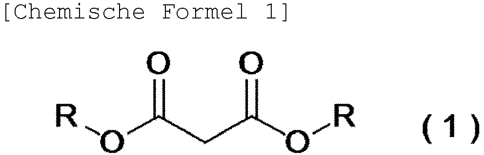
- Verfahren nach einem der Ansprüche 1 bis 11, wobei der Ketomalonsäurediester ein Ketomalonsäurediester ist, der durch die folgende allgemeine Formel (2) dargestellt ist

- Vorrichtung zur kontinuierlichen Herstellung, dadurch gekennzeichnet, dass die Vorrichtung Folgendes umfasst:(1) einen Mischteil, der zum Mischen eines Malonsäurediesters, einer Carbonsäureverbindung und einer Verbindung von chloriger Säure konfiguriert ist;(2) einen Temperaturerhöhungsteil, der konfiguriert ist, um die Temperatur des gemischten Gemisches davon zu erhöhen; und(3) einen Reaktionsteil, der konfiguriert ist, um das Gemisch mit einer durch den Temperaturerhöhungsteil erhöhten Temperatur umzusetzen, um kontinuierlich einen entsprechenden Ketomalonsäurediester oder ein Hydrat davon aus dem Malonsäurediester als eine Rohmaterialverbindung herzustellen,
wobei der Temperaturerhöhungsteil (2) und der Reaktionsteil (3) ein oder zwei oder mehrere röhrenförmige (r) Strömungsreaktor (en) sind, und ein äquivalenter Durchmesser der röhrenförmigen Strömungsreaktoren 0,5 mm bis 50 mm beträgt,
wobei der Temperaturerhöhungsteil und der Reaktionsteil in einem röhrenförmigen Strömungsreaktor vorliegen und die Länge der Röhre des einen röhrenförmigen Strömungsreaktors 9 m bis 50 m beträgt. - Vorrichtung zur kontinuierlichen Herstellung nach Anspruch 13, wobei die Vorrichtung Folgendes umfasst:
(4) einen Alterungsteil, der konfiguriert ist, um das Reaktionsgemisch, das in dem Verfahren des Umsetzens des Gemisches erhalten wird, weiter zu altern, zusätzlich zu den Teilen von (1) bis (3). - Vorrichtung zur kontinuierlichen Herstellung nach Anspruch 14, wobei der Alterungsteil ein oder zwei oder mehrere röhrenförmige(r) Strömungsreaktor(en) ist.
- Vorrichtung zur kontinuierlichen Herstellung nach Anspruch 13, wobei die Vorrichtung Folgendes umfasst:
(5) einen Quenchteil, der konfiguriert ist, um eine Reaktion zu quenchen, zusätzlich zu den Teilen von (1) bis (3). - Vorrichtung zur kontinuierlichen Herstellung nach Anspruch 14 oder 15, wobei die Vorrichtung Folgendes umfasst:
(5) einen Quenchteil, der konfiguriert ist, um eine Reaktion zu quenchen, zusätzlich zu den Teilen von (1) bis (4). - Vorrichtung zur kontinuierlichen Herstellung nach Anspruch 16 oder 17, wobei der Quenchteil ein oder zwei oder mehrere röhrenförmige(r) Strömungsreaktor(en) ist.
Applications Claiming Priority (2)
| Application Number | Priority Date | Filing Date | Title |
|---|---|---|---|
| JP2014027231 | 2014-02-17 | ||
| PCT/JP2015/053334 WO2015122361A1 (ja) | 2014-02-17 | 2015-02-06 | 流通反応器を用いたケトマロン酸化合物の連続製造方法 |
Publications (3)
| Publication Number | Publication Date |
|---|---|
| EP3109227A1 EP3109227A1 (de) | 2016-12-28 |
| EP3109227A4 EP3109227A4 (de) | 2017-09-13 |
| EP3109227B1 true EP3109227B1 (de) | 2020-04-08 |
Family
ID=53800108
Family Applications (1)
| Application Number | Title | Priority Date | Filing Date |
|---|---|---|---|
| EP15748585.5A Active EP3109227B1 (de) | 2014-02-17 | 2015-02-06 | Verfahren zur kontinuierlichen herstellung einer ketomalonsäureverbindung mit einem strömungsreaktor |
Country Status (10)
| Country | Link |
|---|---|
| US (2) | US10035753B2 (de) |
| EP (1) | EP3109227B1 (de) |
| JP (1) | JP6017710B2 (de) |
| KR (1) | KR102134407B1 (de) |
| CN (1) | CN105980345B (de) |
| AU (1) | AU2015216279B2 (de) |
| ES (1) | ES2805462T3 (de) |
| IL (1) | IL247284B (de) |
| TW (1) | TWI679191B (de) |
| WO (1) | WO2015122361A1 (de) |
Families Citing this family (5)
| Publication number | Priority date | Publication date | Assignee | Title |
|---|---|---|---|---|
| TW201829363A (zh) * | 2016-12-05 | 2018-08-16 | 日商組合化學工業股份有限公司 | 三側氧基丙烷化合物的製造法 |
| CN108212044B (zh) * | 2018-01-30 | 2024-04-26 | 凯莱英医药化学(阜新)技术有限公司 | 金属-溴代芳烃的连续置换反应设备、连续置换方法及二者的应用 |
| CN110452119A (zh) * | 2019-08-30 | 2019-11-15 | 苏州汉德创宏生化科技有限公司 | 一种酮基丙二酸二乙酯单水合物的合成方法 |
| CN115646377A (zh) * | 2022-11-16 | 2023-01-31 | 陕西延长石油(集团)有限责任公司 | 一种连续化生产α-烷基酯的反应系统及方法 |
| CN115819230A (zh) * | 2022-11-17 | 2023-03-21 | 苏州汉德创宏生化科技有限公司 | 一种羰基丙二酸二酯的合成方法 |
Family Cites Families (12)
| Publication number | Priority date | Publication date | Assignee | Title |
|---|---|---|---|---|
| AU4061378A (en) * | 1977-10-19 | 1980-04-17 | Merck & Co., Inc. | 1-azabicyclo (3.2.0) hept-2-enes |
| EP0008864A1 (de) | 1978-08-15 | 1980-03-19 | FISONS plc | Pyridopyrazin- und Chinoxalinderivate, Verfahren zu ihrer Herstellung, und sie enthaltende pharmazeutische Zusammensetzungen |
| CH652709A5 (de) * | 1983-01-06 | 1985-11-29 | Lonza Ag | Verfahren zur herstellung von estern der mesoxalsaeure. |
| IT1175533B (it) | 1984-06-20 | 1987-07-01 | Montedison Spa | Processo per la preparazione di composti carbonilici |
| JPH08151346A (ja) | 1994-11-25 | 1996-06-11 | Kao Corp | ケトマロン酸の製造方法 |
| US6348461B1 (en) | 1997-09-01 | 2002-02-19 | Kyorin Pharmaceutical Co., Ltd. | 6,7-asymmetrically disubstituted quinoxalinecarboxylic acid derivatives, addition salts thereof, and processes for the preparation of both |
| EP1070054A1 (de) | 1998-04-08 | 2001-01-24 | Takeda Chemical Industries, Ltd. | Aminverbindungen, ihre herstellung und ihre verwendung als somatostatin rezeptor antagonisten oder agonisten |
| WO2005021547A2 (en) | 2003-08-28 | 2005-03-10 | Pharmaxis Pty Ltd. | Heterocyclic cannabinoid cb2 receptor antagonists |
| EP2447243B1 (de) * | 2009-06-26 | 2014-04-02 | Ihara Chemical Industry Co., Ltd. | Verfahren zur herstellung von ketomalonsäureverbindungen oder hydraten davon |
| EP2404666A1 (de) * | 2010-07-09 | 2012-01-11 | Rhodia Opérations | Modul zur kontinuierlichen Umwandlung mindestens eines flüssigen Produkts, entsprechende Einheit und entsprechendes Verfahren |
| CN201692802U (zh) * | 2010-06-08 | 2011-01-05 | 上海三爱富新材料股份有限公司 | 用于连续生产六氟环氧丙烷的设备 |
| JP5921500B2 (ja) * | 2013-07-19 | 2016-05-24 | イハラケミカル工業株式会社 | ケトマロン酸化合物の製造方法 |
-
2015
- 2015-02-06 EP EP15748585.5A patent/EP3109227B1/de active Active
- 2015-02-06 KR KR1020167024819A patent/KR102134407B1/ko active Active
- 2015-02-06 US US15/119,310 patent/US10035753B2/en active Active
- 2015-02-06 ES ES15748585T patent/ES2805462T3/es active Active
- 2015-02-06 WO PCT/JP2015/053334 patent/WO2015122361A1/ja not_active Ceased
- 2015-02-06 JP JP2015562799A patent/JP6017710B2/ja active Active
- 2015-02-06 AU AU2015216279A patent/AU2015216279B2/en active Active
- 2015-02-06 CN CN201580008270.XA patent/CN105980345B/zh active Active
- 2015-02-10 TW TW104104349A patent/TWI679191B/zh active
-
2016
- 2016-08-15 IL IL247284A patent/IL247284B/en active IP Right Grant
-
2018
- 2018-06-28 US US16/021,429 patent/US20180305290A1/en not_active Abandoned
Non-Patent Citations (1)
| Title |
|---|
| None * |
Also Published As
| Publication number | Publication date |
|---|---|
| WO2015122361A1 (ja) | 2015-08-20 |
| CN105980345B (zh) | 2019-12-20 |
| AU2015216279B2 (en) | 2018-01-18 |
| US20180305290A1 (en) | 2018-10-25 |
| IL247284B (en) | 2020-04-30 |
| TWI679191B (zh) | 2019-12-11 |
| ES2805462T3 (es) | 2021-02-12 |
| JPWO2015122361A1 (ja) | 2017-03-30 |
| IL247284A0 (en) | 2016-09-29 |
| AU2015216279A1 (en) | 2016-09-08 |
| KR20160122770A (ko) | 2016-10-24 |
| CN105980345A (zh) | 2016-09-28 |
| EP3109227A4 (de) | 2017-09-13 |
| US10035753B2 (en) | 2018-07-31 |
| KR102134407B1 (ko) | 2020-07-15 |
| EP3109227A1 (de) | 2016-12-28 |
| US20170008829A1 (en) | 2017-01-12 |
| TW201538474A (zh) | 2015-10-16 |
| JP6017710B2 (ja) | 2016-11-02 |
Similar Documents
| Publication | Publication Date | Title |
|---|---|---|
| US20180305290A1 (en) | Method for continuously producing ketomalonic acid compound using flow reactor | |
| Malet-Sanz et al. | Preparation of arylsulfonyl chlorides by chlorosulfonylation of in situ generated diazonium salts using a continuous flow reactor | |
| Damm et al. | Continuous-flow synthesis of adipic acid from cyclohexene using hydrogen peroxide in high-temperature explosive regimes. | |
| WO2010150548A1 (ja) | ケトマロン酸化合物又はその抱水体の製造法 | |
| JP6911143B2 (ja) | ピラゾール又はピリミジノンの新しい製造方法 | |
| JP7030059B2 (ja) | トリオキソプロパン化合物の製造法 | |
| JP4465048B2 (ja) | N−置換3−ヒドロキシピラゾールの製造方法 | |
| US8609873B2 (en) | Process for making and using HOF.RCN | |
| CN109071411B (zh) | 制造硝基苯化合物的方法 | |
| JPWO2017014214A1 (ja) | 4−(トリフルオロメチルスルホニル)フェノール化合物の製造方法 | |
| KR102034610B1 (ko) | 케토말론산 화합물의 제조방법 | |
| CN110590711B (zh) | 一种六氟环氧丙烷的制备方法 | |
| EP4087834B1 (de) | Verfahren zur herstellung von gesättigten aliphatischen c3-5-carbonsäuren | |
| EP4200273B1 (de) | Verfahren zur herstellung von c6-12 gesättigten aliphatischen carbonsäuren | |
| US20070027211A1 (en) | Process for production of bicalutamide | |
| JP2005314373A (ja) | 酸化反応方法 | |
| US20200031748A1 (en) | Mixture for Use as a Liquid Sorption Agent in Methanol Synthesis and Methanol Synthesis Process Using Said Mixture | |
| JPS6247867B2 (de) |
Legal Events
| Date | Code | Title | Description |
|---|---|---|---|
| PUAI | Public reference made under article 153(3) epc to a published international application that has entered the european phase |
Free format text: ORIGINAL CODE: 0009012 |
|
| STAA | Information on the status of an ep patent application or granted ep patent |
Free format text: STATUS: REQUEST FOR EXAMINATION WAS MADE |
|
| 17P | Request for examination filed |
Effective date: 20160825 |
|
| AK | Designated contracting states |
Kind code of ref document: A1 Designated state(s): AL AT BE BG CH CY CZ DE DK EE ES FI FR GB GR HR HU IE IS IT LI LT LU LV MC MK MT NL NO PL PT RO RS SE SI SK SM TR |
|
| AX | Request for extension of the european patent |
Extension state: BA ME |
|
| DAX | Request for extension of the european patent (deleted) | ||
| A4 | Supplementary search report drawn up and despatched |
Effective date: 20170816 |
|
| RIC1 | Information provided on ipc code assigned before grant |
Ipc: C07C 69/716 20060101ALI20170809BHEP Ipc: C07C 67/31 20060101ALI20170809BHEP Ipc: C07B 61/00 20060101ALI20170809BHEP Ipc: C07C 67/313 20060101AFI20170809BHEP Ipc: C07C 69/675 20060101ALI20170809BHEP |
|
| RAP1 | Party data changed (applicant data changed or rights of an application transferred) |
Owner name: KUMIAI CHEMICAL INDUSTRY CO., LTD. |
|
| STAA | Information on the status of an ep patent application or granted ep patent |
Free format text: STATUS: EXAMINATION IS IN PROGRESS |
|
| 17Q | First examination report despatched |
Effective date: 20181204 |
|
| GRAP | Despatch of communication of intention to grant a patent |
Free format text: ORIGINAL CODE: EPIDOSNIGR1 |
|
| STAA | Information on the status of an ep patent application or granted ep patent |
Free format text: STATUS: GRANT OF PATENT IS INTENDED |
|
| INTG | Intention to grant announced |
Effective date: 20190920 |
|
| GRAS | Grant fee paid |
Free format text: ORIGINAL CODE: EPIDOSNIGR3 |
|
| RIN1 | Information on inventor provided before grant (corrected) |
Inventor name: TANI, SHINKI |
|
| GRAA | (expected) grant |
Free format text: ORIGINAL CODE: 0009210 |
|
| STAA | Information on the status of an ep patent application or granted ep patent |
Free format text: STATUS: THE PATENT HAS BEEN GRANTED |
|
| AK | Designated contracting states |
Kind code of ref document: B1 Designated state(s): AL AT BE BG CH CY CZ DE DK EE ES FI FR GB GR HR HU IE IS IT LI LT LU LV MC MK MT NL NO PL PT RO RS SE SI SK SM TR |
|
| REG | Reference to a national code |
Ref country code: AT Ref legal event code: REF Ref document number: 1254188 Country of ref document: AT Kind code of ref document: T Effective date: 20200415 Ref country code: CH Ref legal event code: EP |
|
| REG | Reference to a national code |
Ref country code: DE Ref legal event code: R096 Ref document number: 602015050300 Country of ref document: DE |
|
| REG | Reference to a national code |
Ref country code: IE Ref legal event code: FG4D |
|
| REG | Reference to a national code |
Ref country code: CH Ref legal event code: NV Representative=s name: RENTSCH PARTNER AG, CH |
|
| REG | Reference to a national code |
Ref country code: NL Ref legal event code: MP Effective date: 20200408 |
|
| REG | Reference to a national code |
Ref country code: LT Ref legal event code: MG4D |
|
| PG25 | Lapsed in a contracting state [announced via postgrant information from national office to epo] |
Ref country code: NL Free format text: LAPSE BECAUSE OF FAILURE TO SUBMIT A TRANSLATION OF THE DESCRIPTION OR TO PAY THE FEE WITHIN THE PRESCRIBED TIME-LIMIT Effective date: 20200408 Ref country code: GR Free format text: LAPSE BECAUSE OF FAILURE TO SUBMIT A TRANSLATION OF THE DESCRIPTION OR TO PAY THE FEE WITHIN THE PRESCRIBED TIME-LIMIT Effective date: 20200709 Ref country code: SE Free format text: LAPSE BECAUSE OF FAILURE TO SUBMIT A TRANSLATION OF THE DESCRIPTION OR TO PAY THE FEE WITHIN THE PRESCRIBED TIME-LIMIT Effective date: 20200408 Ref country code: IS Free format text: LAPSE BECAUSE OF FAILURE TO SUBMIT A TRANSLATION OF THE DESCRIPTION OR TO PAY THE FEE WITHIN THE PRESCRIBED TIME-LIMIT Effective date: 20200808 Ref country code: FI Free format text: LAPSE BECAUSE OF FAILURE TO SUBMIT A TRANSLATION OF THE DESCRIPTION OR TO PAY THE FEE WITHIN THE PRESCRIBED TIME-LIMIT Effective date: 20200408 Ref country code: LT Free format text: LAPSE BECAUSE OF FAILURE TO SUBMIT A TRANSLATION OF THE DESCRIPTION OR TO PAY THE FEE WITHIN THE PRESCRIBED TIME-LIMIT Effective date: 20200408 Ref country code: PT Free format text: LAPSE BECAUSE OF FAILURE TO SUBMIT A TRANSLATION OF THE DESCRIPTION OR TO PAY THE FEE WITHIN THE PRESCRIBED TIME-LIMIT Effective date: 20200817 Ref country code: NO Free format text: LAPSE BECAUSE OF FAILURE TO SUBMIT A TRANSLATION OF THE DESCRIPTION OR TO PAY THE FEE WITHIN THE PRESCRIBED TIME-LIMIT Effective date: 20200708 |
|
| REG | Reference to a national code |
Ref country code: AT Ref legal event code: MK05 Ref document number: 1254188 Country of ref document: AT Kind code of ref document: T Effective date: 20200408 |
|
| PG25 | Lapsed in a contracting state [announced via postgrant information from national office to epo] |
Ref country code: HR Free format text: LAPSE BECAUSE OF FAILURE TO SUBMIT A TRANSLATION OF THE DESCRIPTION OR TO PAY THE FEE WITHIN THE PRESCRIBED TIME-LIMIT Effective date: 20200408 Ref country code: LV Free format text: LAPSE BECAUSE OF FAILURE TO SUBMIT A TRANSLATION OF THE DESCRIPTION OR TO PAY THE FEE WITHIN THE PRESCRIBED TIME-LIMIT Effective date: 20200408 Ref country code: RS Free format text: LAPSE BECAUSE OF FAILURE TO SUBMIT A TRANSLATION OF THE DESCRIPTION OR TO PAY THE FEE WITHIN THE PRESCRIBED TIME-LIMIT Effective date: 20200408 Ref country code: BG Free format text: LAPSE BECAUSE OF FAILURE TO SUBMIT A TRANSLATION OF THE DESCRIPTION OR TO PAY THE FEE WITHIN THE PRESCRIBED TIME-LIMIT Effective date: 20200708 |
|
| PG25 | Lapsed in a contracting state [announced via postgrant information from national office to epo] |
Ref country code: AL Free format text: LAPSE BECAUSE OF FAILURE TO SUBMIT A TRANSLATION OF THE DESCRIPTION OR TO PAY THE FEE WITHIN THE PRESCRIBED TIME-LIMIT Effective date: 20200408 |
|
| REG | Reference to a national code |
Ref country code: DE Ref legal event code: R097 Ref document number: 602015050300 Country of ref document: DE |
|
| PG25 | Lapsed in a contracting state [announced via postgrant information from national office to epo] |
Ref country code: RO Free format text: LAPSE BECAUSE OF FAILURE TO SUBMIT A TRANSLATION OF THE DESCRIPTION OR TO PAY THE FEE WITHIN THE PRESCRIBED TIME-LIMIT Effective date: 20200408 Ref country code: CZ Free format text: LAPSE BECAUSE OF FAILURE TO SUBMIT A TRANSLATION OF THE DESCRIPTION OR TO PAY THE FEE WITHIN THE PRESCRIBED TIME-LIMIT Effective date: 20200408 Ref country code: SM Free format text: LAPSE BECAUSE OF FAILURE TO SUBMIT A TRANSLATION OF THE DESCRIPTION OR TO PAY THE FEE WITHIN THE PRESCRIBED TIME-LIMIT Effective date: 20200408 Ref country code: AT Free format text: LAPSE BECAUSE OF FAILURE TO SUBMIT A TRANSLATION OF THE DESCRIPTION OR TO PAY THE FEE WITHIN THE PRESCRIBED TIME-LIMIT Effective date: 20200408 Ref country code: EE Free format text: LAPSE BECAUSE OF FAILURE TO SUBMIT A TRANSLATION OF THE DESCRIPTION OR TO PAY THE FEE WITHIN THE PRESCRIBED TIME-LIMIT Effective date: 20200408 Ref country code: DK Free format text: LAPSE BECAUSE OF FAILURE TO SUBMIT A TRANSLATION OF THE DESCRIPTION OR TO PAY THE FEE WITHIN THE PRESCRIBED TIME-LIMIT Effective date: 20200408 |
|
| PLBE | No opposition filed within time limit |
Free format text: ORIGINAL CODE: 0009261 |
|
| REG | Reference to a national code |
Ref country code: ES Ref legal event code: FG2A Ref document number: 2805462 Country of ref document: ES Kind code of ref document: T3 Effective date: 20210212 |
|
| STAA | Information on the status of an ep patent application or granted ep patent |
Free format text: STATUS: NO OPPOSITION FILED WITHIN TIME LIMIT |
|
| PG25 | Lapsed in a contracting state [announced via postgrant information from national office to epo] |
Ref country code: SK Free format text: LAPSE BECAUSE OF FAILURE TO SUBMIT A TRANSLATION OF THE DESCRIPTION OR TO PAY THE FEE WITHIN THE PRESCRIBED TIME-LIMIT Effective date: 20200408 Ref country code: PL Free format text: LAPSE BECAUSE OF FAILURE TO SUBMIT A TRANSLATION OF THE DESCRIPTION OR TO PAY THE FEE WITHIN THE PRESCRIBED TIME-LIMIT Effective date: 20200408 |
|
| 26N | No opposition filed |
Effective date: 20210112 |
|
| PG25 | Lapsed in a contracting state [announced via postgrant information from national office to epo] |
Ref country code: SI Free format text: LAPSE BECAUSE OF FAILURE TO SUBMIT A TRANSLATION OF THE DESCRIPTION OR TO PAY THE FEE WITHIN THE PRESCRIBED TIME-LIMIT Effective date: 20200408 |
|
| PG25 | Lapsed in a contracting state [announced via postgrant information from national office to epo] |
Ref country code: MC Free format text: LAPSE BECAUSE OF FAILURE TO SUBMIT A TRANSLATION OF THE DESCRIPTION OR TO PAY THE FEE WITHIN THE PRESCRIBED TIME-LIMIT Effective date: 20200408 |
|
| REG | Reference to a national code |
Ref country code: BE Ref legal event code: MM Effective date: 20210228 |
|
| PG25 | Lapsed in a contracting state [announced via postgrant information from national office to epo] |
Ref country code: LU Free format text: LAPSE BECAUSE OF NON-PAYMENT OF DUE FEES Effective date: 20210206 |
|
| PG25 | Lapsed in a contracting state [announced via postgrant information from national office to epo] |
Ref country code: IE Free format text: LAPSE BECAUSE OF NON-PAYMENT OF DUE FEES Effective date: 20210206 |
|
| PG25 | Lapsed in a contracting state [announced via postgrant information from national office to epo] |
Ref country code: BE Free format text: LAPSE BECAUSE OF NON-PAYMENT OF DUE FEES Effective date: 20210228 |
|
| PG25 | Lapsed in a contracting state [announced via postgrant information from national office to epo] |
Ref country code: HU Free format text: LAPSE BECAUSE OF FAILURE TO SUBMIT A TRANSLATION OF THE DESCRIPTION OR TO PAY THE FEE WITHIN THE PRESCRIBED TIME-LIMIT; INVALID AB INITIO Effective date: 20150206 |
|
| PG25 | Lapsed in a contracting state [announced via postgrant information from national office to epo] |
Ref country code: CY Free format text: LAPSE BECAUSE OF FAILURE TO SUBMIT A TRANSLATION OF THE DESCRIPTION OR TO PAY THE FEE WITHIN THE PRESCRIBED TIME-LIMIT Effective date: 20200408 |
|
| PG25 | Lapsed in a contracting state [announced via postgrant information from national office to epo] |
Ref country code: MK Free format text: LAPSE BECAUSE OF FAILURE TO SUBMIT A TRANSLATION OF THE DESCRIPTION OR TO PAY THE FEE WITHIN THE PRESCRIBED TIME-LIMIT Effective date: 20200408 |
|
| PG25 | Lapsed in a contracting state [announced via postgrant information from national office to epo] |
Ref country code: TR Free format text: LAPSE BECAUSE OF FAILURE TO SUBMIT A TRANSLATION OF THE DESCRIPTION OR TO PAY THE FEE WITHIN THE PRESCRIBED TIME-LIMIT Effective date: 20200408 |
|
| PG25 | Lapsed in a contracting state [announced via postgrant information from national office to epo] |
Ref country code: MT Free format text: LAPSE BECAUSE OF FAILURE TO SUBMIT A TRANSLATION OF THE DESCRIPTION OR TO PAY THE FEE WITHIN THE PRESCRIBED TIME-LIMIT Effective date: 20200408 |
|
| PGFP | Annual fee paid to national office [announced via postgrant information from national office to epo] |
Ref country code: DE Payment date: 20250226 Year of fee payment: 11 |
|
| PGFP | Annual fee paid to national office [announced via postgrant information from national office to epo] |
Ref country code: ES Payment date: 20250318 Year of fee payment: 11 |
|
| PGFP | Annual fee paid to national office [announced via postgrant information from national office to epo] |
Ref country code: CH Payment date: 20250301 Year of fee payment: 11 |
|
| PGFP | Annual fee paid to national office [announced via postgrant information from national office to epo] |
Ref country code: FR Payment date: 20250219 Year of fee payment: 11 |
|
| PGFP | Annual fee paid to national office [announced via postgrant information from national office to epo] |
Ref country code: IT Payment date: 20250228 Year of fee payment: 11 Ref country code: GB Payment date: 20250220 Year of fee payment: 11 |