EP3109366B1 - Baumaschine - Google Patents
Baumaschine Download PDFInfo
- Publication number
- EP3109366B1 EP3109366B1 EP15751923.2A EP15751923A EP3109366B1 EP 3109366 B1 EP3109366 B1 EP 3109366B1 EP 15751923 A EP15751923 A EP 15751923A EP 3109366 B1 EP3109366 B1 EP 3109366B1
- Authority
- EP
- European Patent Office
- Prior art keywords
- swing
- boom
- speed reduction
- reduction amount
- speed
- Prior art date
- Legal status (The legal status is an assumption and is not a legal conclusion. Google has not performed a legal analysis and makes no representation as to the accuracy of the status listed.)
- Active
Links
Images


Classifications
-
- E—FIXED CONSTRUCTIONS
- E02—HYDRAULIC ENGINEERING; FOUNDATIONS; SOIL SHIFTING
- E02F—DREDGING; SOIL-SHIFTING
- E02F9/00—Component parts of dredgers or soil-shifting machines, not restricted to one of the kinds covered by groups E02F3/00 - E02F7/00
- E02F9/08—Superstructures; Supports for superstructures
- E02F9/10—Supports for movable superstructures mounted on travelling or walking gears or on other superstructures
- E02F9/12—Slewing or traversing gears
- E02F9/121—Turntables, i.e. structure rotatable about 360°
- E02F9/123—Drives or control devices specially adapted therefor
-
- E—FIXED CONSTRUCTIONS
- E02—HYDRAULIC ENGINEERING; FOUNDATIONS; SOIL SHIFTING
- E02F—DREDGING; SOIL-SHIFTING
- E02F3/00—Dredgers; Soil-shifting machines
- E02F3/04—Dredgers; Soil-shifting machines mechanically-driven
- E02F3/28—Dredgers; Soil-shifting machines mechanically-driven with digging tools mounted on a dipper- or bucket-arm, i.e. there is either one arm or a pair of arms, e.g. dippers, buckets
- E02F3/30—Dredgers; Soil-shifting machines mechanically-driven with digging tools mounted on a dipper- or bucket-arm, i.e. there is either one arm or a pair of arms, e.g. dippers, buckets with a dipper-arm pivoted on a cantilever beam, i.e. boom
- E02F3/32—Dredgers; Soil-shifting machines mechanically-driven with digging tools mounted on a dipper- or bucket-arm, i.e. there is either one arm or a pair of arms, e.g. dippers, buckets with a dipper-arm pivoted on a cantilever beam, i.e. boom working downwardly and towards the machine, e.g. with backhoes
-
- E—FIXED CONSTRUCTIONS
- E02—HYDRAULIC ENGINEERING; FOUNDATIONS; SOIL SHIFTING
- E02F—DREDGING; SOIL-SHIFTING
- E02F3/00—Dredgers; Soil-shifting machines
- E02F3/04—Dredgers; Soil-shifting machines mechanically-driven
- E02F3/28—Dredgers; Soil-shifting machines mechanically-driven with digging tools mounted on a dipper- or bucket-arm, i.e. there is either one arm or a pair of arms, e.g. dippers, buckets
- E02F3/36—Component parts
- E02F3/42—Drives for dippers, buckets, dipper-arms or bucket-arms
- E02F3/43—Control of dipper or bucket position; Control of sequence of drive operations
- E02F3/435—Control of dipper or bucket position; Control of sequence of drive operations for dipper-arms, backhoes or the like
-
- E—FIXED CONSTRUCTIONS
- E02—HYDRAULIC ENGINEERING; FOUNDATIONS; SOIL SHIFTING
- E02F—DREDGING; SOIL-SHIFTING
- E02F9/00—Component parts of dredgers or soil-shifting machines, not restricted to one of the kinds covered by groups E02F3/00 - E02F7/00
- E02F9/26—Indicating devices
- E02F9/264—Sensors and their calibration for indicating the position of the work tool
- E02F9/265—Sensors and their calibration for indicating the position of the work tool with follow-up actions (e.g. control signals sent to actuate the work tool)
-
- F—MECHANICAL ENGINEERING; LIGHTING; HEATING; WEAPONS; BLASTING
- F15—FLUID-PRESSURE ACTUATORS; HYDRAULICS OR PNEUMATICS IN GENERAL
- F15B—SYSTEMS ACTING BY MEANS OF FLUIDS IN GENERAL; FLUID-PRESSURE ACTUATORS, e.g. SERVOMOTORS; DETAILS OF FLUID-PRESSURE SYSTEMS, NOT OTHERWISE PROVIDED FOR
- F15B11/00—Servomotor systems without provision for follow-up action; Circuits therefor
- F15B11/08—Servomotor systems without provision for follow-up action; Circuits therefor with only one servomotor
-
- F—MECHANICAL ENGINEERING; LIGHTING; HEATING; WEAPONS; BLASTING
- F15—FLUID-PRESSURE ACTUATORS; HYDRAULICS OR PNEUMATICS IN GENERAL
- F15B—SYSTEMS ACTING BY MEANS OF FLUIDS IN GENERAL; FLUID-PRESSURE ACTUATORS, e.g. SERVOMOTORS; DETAILS OF FLUID-PRESSURE SYSTEMS, NOT OTHERWISE PROVIDED FOR
- F15B13/00—Details of servomotor systems ; Valves for servomotor systems
- F15B13/02—Fluid distribution or supply devices characterised by their adaptation to the control of servomotors
- F15B13/04—Fluid distribution or supply devices characterised by their adaptation to the control of servomotors for use with a single servomotor
- F15B13/0401—Valve members; Fluid interconnections therefor
-
- F—MECHANICAL ENGINEERING; LIGHTING; HEATING; WEAPONS; BLASTING
- F15—FLUID-PRESSURE ACTUATORS; HYDRAULICS OR PNEUMATICS IN GENERAL
- F15B—SYSTEMS ACTING BY MEANS OF FLUIDS IN GENERAL; FLUID-PRESSURE ACTUATORS, e.g. SERVOMOTORS; DETAILS OF FLUID-PRESSURE SYSTEMS, NOT OTHERWISE PROVIDED FOR
- F15B21/00—Common features of fluid actuator systems; Fluid-pressure actuator systems or details thereof, not covered by any other group of this subclass
- F15B21/08—Servomotor systems incorporating electrically operated control means
-
- F—MECHANICAL ENGINEERING; LIGHTING; HEATING; WEAPONS; BLASTING
- F15—FLUID-PRESSURE ACTUATORS; HYDRAULICS OR PNEUMATICS IN GENERAL
- F15B—SYSTEMS ACTING BY MEANS OF FLUIDS IN GENERAL; FLUID-PRESSURE ACTUATORS, e.g. SERVOMOTORS; DETAILS OF FLUID-PRESSURE SYSTEMS, NOT OTHERWISE PROVIDED FOR
- F15B2211/00—Circuits for servomotor systems
- F15B2211/20—Fluid pressure source, e.g. accumulator or variable axial piston pump
- F15B2211/205—Systems with pumps
-
- F—MECHANICAL ENGINEERING; LIGHTING; HEATING; WEAPONS; BLASTING
- F15—FLUID-PRESSURE ACTUATORS; HYDRAULICS OR PNEUMATICS IN GENERAL
- F15B—SYSTEMS ACTING BY MEANS OF FLUIDS IN GENERAL; FLUID-PRESSURE ACTUATORS, e.g. SERVOMOTORS; DETAILS OF FLUID-PRESSURE SYSTEMS, NOT OTHERWISE PROVIDED FOR
- F15B2211/00—Circuits for servomotor systems
- F15B2211/60—Circuit components or control therefor
- F15B2211/63—Electronic controllers
- F15B2211/6303—Electronic controllers using input signals
- F15B2211/6306—Electronic controllers using input signals representing a pressure
- F15B2211/6313—Electronic controllers using input signals representing a pressure the pressure being a load pressure
-
- F—MECHANICAL ENGINEERING; LIGHTING; HEATING; WEAPONS; BLASTING
- F15—FLUID-PRESSURE ACTUATORS; HYDRAULICS OR PNEUMATICS IN GENERAL
- F15B—SYSTEMS ACTING BY MEANS OF FLUIDS IN GENERAL; FLUID-PRESSURE ACTUATORS, e.g. SERVOMOTORS; DETAILS OF FLUID-PRESSURE SYSTEMS, NOT OTHERWISE PROVIDED FOR
- F15B2211/00—Circuits for servomotor systems
- F15B2211/70—Output members, e.g. hydraulic motors or cylinders or control therefor
- F15B2211/705—Output members, e.g. hydraulic motors or cylinders or control therefor characterised by the type of output members or actuators
- F15B2211/7051—Linear output members
- F15B2211/7053—Double-acting output members
-
- F—MECHANICAL ENGINEERING; LIGHTING; HEATING; WEAPONS; BLASTING
- F15—FLUID-PRESSURE ACTUATORS; HYDRAULICS OR PNEUMATICS IN GENERAL
- F15B—SYSTEMS ACTING BY MEANS OF FLUIDS IN GENERAL; FLUID-PRESSURE ACTUATORS, e.g. SERVOMOTORS; DETAILS OF FLUID-PRESSURE SYSTEMS, NOT OTHERWISE PROVIDED FOR
- F15B2211/00—Circuits for servomotor systems
- F15B2211/70—Output members, e.g. hydraulic motors or cylinders or control therefor
- F15B2211/705—Output members, e.g. hydraulic motors or cylinders or control therefor characterised by the type of output members or actuators
- F15B2211/7058—Rotary output members
-
- F—MECHANICAL ENGINEERING; LIGHTING; HEATING; WEAPONS; BLASTING
- F15—FLUID-PRESSURE ACTUATORS; HYDRAULICS OR PNEUMATICS IN GENERAL
- F15B—SYSTEMS ACTING BY MEANS OF FLUIDS IN GENERAL; FLUID-PRESSURE ACTUATORS, e.g. SERVOMOTORS; DETAILS OF FLUID-PRESSURE SYSTEMS, NOT OTHERWISE PROVIDED FOR
- F15B2211/00—Circuits for servomotor systems
- F15B2211/70—Output members, e.g. hydraulic motors or cylinders or control therefor
- F15B2211/71—Multiple output members, e.g. multiple hydraulic motors or cylinders
- F15B2211/7114—Multiple output members, e.g. multiple hydraulic motors or cylinders with direct connection between the chambers of different actuators
- F15B2211/7128—Multiple output members, e.g. multiple hydraulic motors or cylinders with direct connection between the chambers of different actuators the chambers being connected in parallel
Definitions
- the present invention relates to a construction machine, such as a hydraulic excavator, that includes a work implement capable of vertical movement and a swing structure.
- US 2009/301075 A1 discloses a construction machine, whereby the power consumption of the slewing motor and the boom cylinder during combined boom raising and slewing operation is balanced.
- EP 1 905 902 A2 and WO 2013/002152 A1 both disclose a construction machine, whereby the torque of the rotation motor is controlled in the direction of slowing down acceleration of the rotation in accordance with an increase in the load of the boom cylinder at the time of a combined raising and slewing operation.
- the rising speed of the boom varies even if the boom raising operation amount is the same.
- the swing operation amount is the same, the swing speed varies little even when the load on the boom varies.
- the rising amount of the boom per time differs depending on the boom load; therefore, the locus of a front work implement at the time of a swing and boom raising operation varies depending on whether the boom load is low or high.
- the present invention has been made in consideration of the above-mentioned circumstances. Accordingly, it is an object of the present invention to provide a construction machine that enables a load acting on a boom to be felt on the basis of motion of a front work implement and, on the other hand, enables the front work implement to be moved along a locus according to operation without being affected by the boom load.
- a construction machine including: a track structure; a swing structure provided on the track structure in a swingable manner; a swing motor that drives and swings the swing structure; a boom connected to the swing structure; a boom cylinder that moves the boom vertically; a swing operation system that instructs a swing operation of the swing structure; a boom operation system that instructs a vertical movement of the boom; a detector that detects a state quantity varying according to a load on the boom cylinder; and a controller that reduces swing speed of the swing structure according to a signal from the detector with respect to a reference swing speed according to a signal of the swing operation, while signals of the swing operation by the swing operation system and a boom raising operation by the boom operation system are being inputted, wherein the controller includes: a boom speed reduction calculation section configured to calculate a boom speed reduction amount ⁇ R with respect to a reference boom raising speed Rs that is suited to an operation amount of the boom operation system on the basis of the signal from
- a load acting on a boom can be felt on the basis of motion of a front work implement and, on the other hand, the front work implement can be moved along a locus according to operation without being affected by the boom load. Consequently, enhancement of operability and safety can be expected.
- a swing and boom raising operation herein means to simultaneously perform a boom raising operation and a swing operation, namely, a situation wherein an input for the boom raising operation and an input for the swing operation overlap each other on a time basis. Therefore, while it is needless to say that a case wherein both the operations are the same as to starting timing and finishing timing is included in the swing and boom raising operation, the period of time during which both the operations are performed in such cases as a case wherein one of operation inputs precedes the other of the operation inputs but wherein the other of the operation inputs is conducted during the time when one of the operation input is continuing is also included in the swing and boom raising operation.
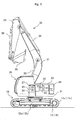
- Fig. 1 is a partial perspective side view of a construction machine according to a first embodiment of the present invention.
- the construction machine illustrated in Fig. 1 is an electrically driven type hydraulic excavator, which includes a track structure 10, a swing structure 20 provided on the track structure 10 in a swingable manner, and an excavator mechanism (front work implement) 30 provided on the swing structure 20 in a vertically movable manner.
- the track structure 10 includes: a pair of left and right crawlers 11a and 11b; a pair of left and right crawler frames 12a and 12b; traveling hydraulic motors 13 and 14 for driving the left and right crawlers 11a and 11b respectively; and speed reduction gears for the traveling hydraulic motors 13 and 14, etc.
- crawlers 11a and 11b and the crawler frames 12a and 12b only those ones on the left side are shown in Fig. 1 .
- the swing structure 20 is mounted on upper portions of the crawler frames 12a and 12b through a swing frame 21.
- the swing frame 21 is provided on upper portions of the crawler frames 12a and 12b through a swing ring in such a manner as to be swingable about a vertical axis.
- the swing ring includes an inner ring connected to the crawler frames 12a and 12b, and an outer ring connected to the swing frame 21, the outer ring being swingable in relation to the inner ring.
- the swing electric motor 25 is supported by the outer ring of the swing ring together with the swing hydraulic motor 27, and has an output shaft meshed with an internal gear of the inner ring through a speed reduction gear 26.
- the swing hydraulic motor 27 is provided coaxially with the swing electric motor 25.
- a capacitor 24 as an electricity accumulation device is connected to the swing electric motor 25, and the swing electric motor 25 is driven by supply of electric power from the capacitor 24. Owing to this configuration, driving forces of the swing hydraulic motor 27 and the swing electric motor 25 are transmitted to the swing ring through the speed reduction gear 26, and the swing structure 20 is swung together with the swing frame 21 in relation to the track structure 10.
- the excavator mechanism 30 is a front work implement of an articulated structure including a boom 31, an arm 34, and a bucket 35.
- the boom 31 is connected to the swing frame 21 of the swing structure 20 by a pin or the like in a vertically movable manner.
- the arm 34 is connected to a tip portion of the boom 31 by a pin or the like so that it can be rotated in forward-rearward directions.
- the bucket 35 is connected to a tip portion of the arm 34 by a pin or the like in a rotatable manner.
- the boom 31, the arm 34 and the bucket 35 are driven by a boom cylinder 32, an arm cylinder 34 and a bucket cylinder 36, respectively.
- the boom cylinder 32, the arm cylinder 34 and the bucket cylinder 36 are hydraulic cylinders.
- the drive system includes a hydraulic system 40 for driving hydraulic actuators, and an electric system for driving electric actuators.
- the hydraulic system 40 drives the aforementioned traveling hydraulic motors 13 and 14, the swing hydraulic motor 27, the boom cylinder 32, the arm cylinder 34, the bucket cylinder 36 and the like.
- the electric system drives the an assist power generation motor 23, the swing electric motor 25 and the like.
- Fig. 2 is a conceptual diagram of the drive system provided in the construction machine according to the first embodiment of the present invention.
- the hydraulic system 40 includes a hydraulic pump 41 as a hydraulic fluid source for generating hydraulic pressure, and a control valve 42 for drive control of each of the hydraulic actuators.
- the hydraulic pump 41 is driven by an engine 22.
- the control valve 42 operates a swing spool 61 (see Fig. 3 ) according to a swing operation command (hydraulic pilot signal) from a swing operation system 72 (see Fig. 3 ), so as to control the flow rate and direction of hydraulic fluid supplied to the swing hydraulic motor 27.
- the control valve 42 operates a boom spool 64 (see Fig. 3 ) according to a boom operation command (hydraulic pilot signal) from a boom operation system 78 (see Fig.
- control valve 42 operates spools corresponding to operation commands (hydraulic pilot signals) from other operation lever systems according to the operation commands, so as to control the flow rates and directions of hydraulic fluids supplied respectively to the arm cylinder 34, the bucket cylinder 36 and the traveling hydraulic motors 13 and 14.
- the various operation systems including the swing operation system 72 and the boom operation system 78 are disposed in a cabin of the track structure 20.
- the electric system includes a power control unit 50 and a main contactor 51, etc.
- the power control unit 50 is connected with the assist power generation motor 23 and the swing electric motor 25, and is connected to the capacitor 24 through the main contactor 51.
- the capacitor 24 is discharged or charged according to the drive conditions (whether in a power running or in a regenerative running) of the assist power generation motor 23 and the swing electric motor 25.
- the drive conditions of the assist power generation motor 23 and the swing electric motor 25 are controlled by the power control unit 50 in accordance with commands from a controller 80.
- the controller 80 generates control commands for the control valve 42, the hydraulic pump 41, and the power control unit 50 on the basis of various input signals, and performs torque control on the swing electric motor 25, delivery flow rate control on the hydraulic pump 41, and the like.
- Input signals to the controller 80 include operation signals from various operation systems, a pressure detection signal from the swing hydraulic motor 27, and an angular velocity signal from the swing electric motor 25.
- Fig. 3 is a block diagram of an essential part of the drive system provided in the construction machine according to the first embodiment of the present invention.
- the controller 80 includes a boom speed reduction amount calculation block 83a (boom speed reduction amount calculation section), a swing speed reduction amount calculation block 83b (swing speed reduction amount calculation section), a swing torque calculation block 83c (swing torque calculation section), and a torque command value calculation block 83d (torque command value calculation section).
- a pilot line of the swing operation system 72 is provided with detectors 74aL and 74aR, and both of lines for suction and discharge of hydraulic fluid into and from the swing hydraulic motor 27 are provided with detectors 74bL and 74bR, respectively.
- a pilot line of the boom operation system (boom operation lever system) 78 is provided with a detector 74c, and a line for suction and discharge of hydraulic fluid into and from a bottom-side fluid chamber of the boom cylinder 32 is provided with a detector 74d.
- Each of the detectors 74aL, 74aR, 74bL, 74bR, 74c and 74d is a hydraulic-to-electric converter for converting a pressure in a hydraulic line into an electrical signal, and outputs a signal to the controller 80.
- the detector 74aL convers into an electrical signal a hydraulic pilot signal generated by an operation input to the swing operation system 72 at the time of instructing a leftward swing operation, and outputs the electrical signal as a detection signal to the swing speed reduction amount calculation block 83b.
- the detector 74aR converts into an electrical signal a hydraulic pilot signal generated by an operation input to the swing operation system 72 at the time of instructing a rightward swing operation, and outputs the electrical signal as a detection signal to the swing speed reduction amount calculation block 83b.
- the detectors 74bL and 74bR convert an operation pressure in the swing hydraulic motor 27 into an electrical signal, and output the electrical signal as a detection signal to the swing torque calculation block 83c.
- the detector 74c convers into an electrical signal a hydraulic pilot signal generated by an operation input to the boom operation system 78 at the time of instructing a boom raising operation, and outputs the electrical signal as a detection signal to the boom speed reduction amount calculation block 83a.
- the detector 74d converts a bottom pressure in the boom cylinder 32 into an electrical signal, and outputs the electrical signal as a detection signal to the boom speed reduction amount calculation block 83a.
- the boom speed reduction amount calculation block 83a calculates a speed reduction amount of boom speed (boom speed reduction amount) ⁇ R with respect to a reference boom raising speed Rs that is suited to an operation amount of the boom operation system 78, based on the signals from the detectors 74c and 74d.
- the reference boom raising speed Rs means a speed at which the boom 31 is raised according to an operation amount of the boom operation system 78 in a no-load condition (a condition where the bucket is empty) or a condition where a predetermined load is exerted.
- a relation (a relation curve, a table or the like) between boom raising operation amount (the signal from the detector 74c) of the boom operation system 78 and the reference boom raising speed Rs is preliminarily stored.
- relations (relation curves, tables or the like) between the boom raising operation amount (the signal from the detector 74c) of the boom operation system 78, bottom pressure (the signal from the detector 74d) of the boom cylinder 32, and the boom speed reduction amount ⁇ R are preliminarily stored.
- the boom speed reduction amount calculation block 83a therefore, on the basis of the signals from the detectors 74c and 74d, the reference boom raising speed Rs suited to the operation amount of the boom operation system 78 is calculated, and, simultaneously, the boom speed reduction amount ⁇ R according to the bottom pressure of the boom cylinder 32 is calculated.
- These calculated values are inputted from the boom speed reduction amount calculation block 83a to the swing speed reduction amount calculation block 83b. Note that it may also be contemplated to let the boom speed reduction amount ⁇ R be a value determined simply by the relation with the bottom pressure of the boom cylinder 32.
- the swing speed reduction amount calculation block 83b calculates a speed reduction amount of swing speed (swing speed reduction amount) ⁇ S with respect to a reference swing speed Ss that is suited to an operation amount of the swing operation system 72, based on the calculated boom speed reduction amount ⁇ R and the signals from the detectors 74aL and 74aR.
- the reference swing speed Ss means an intrinsic speed according to the operation amount of the swing operation system 72.
- the swing speed reduction amount ⁇ S is a correction amount that should be subtracted from the reference swing speed Ss in such a manner that the excavator mechanism 30 will move along a locus that is to be described by the excavator mechanism 30 driven at the reference boom raising speed Rs and the reference swing speed Ss, in the case where a boom speed reduction amount ⁇ R is anticipated due to a boom load.
- the swing speed reduction amount ⁇ S is inputted from the swing speed reduction amount calculation block 83b to the torque command value calculation block 83d.
- the swing speed reduction amount calculation block 83b regulates the value of the speed reduction amount ⁇ S in such a manner that an actual swing speed calculated based on an angular velocity signal ⁇ of the swing electric motor 25 inputted through the power control unit 50 will approach the swing speed S (target).
- swing torque of the swing hydraulic motor 27 is calculated based on the signals from the detectors 74bL and 74bR, and the calculated value is outputted to the torque command value calculation block 83d.
- torque command value calculation bock 83d on the basis of the swing speed reduction amount ⁇ S calculated by the swing speed reduction amount calculation block 83b and the swing torque calculated by the swing torque calculation block 83c, a torque command value EA for the swing electric motor 25 that is necessary for generating the swing speed reduction amount ⁇ S is calculated, and the calculated value is outputted to the power control unit 50.
- the power control unit 50 drives the swing electric motor 25 in accordance with the torque command value EA.
- the swing electric motor 25 is driven as a generator, and a generation output obtained by regeneration of kinetic energy of the swing structure 20 is accumulated into the capacitor 24 by way of the main contactor 51.
- a hydraulic pilot signal generated due to an input to the swing operation system 72 is inputted also to the control valve 42.
- the spool 61 is changed over from a neutral position, and hydraulic fluid delivered from the hydraulic pump 41 is supplied to the swing hydraulic motor 27, to cause driving of the swing hydraulic motor 27. Since the swing electric motor 25 and the swing hydraulic motor 27 are connected directly to each other, a total torque of the torques outputted from these motors 35 and 37 becomes a swing torque that actually acts on the swing structure 20.
- a hydraulic pilot signal generated due to an operation input to the boom operation system 78 simultaneously with the above-mentioned swing drive is inputted also to the control valve 42.
- the spool 64 is changed over from a neutral position, hydraulic fluid delivered from the hydraulic pump 41 is supplied to the boom cylinder 32, and the boom 31 is raised.
- Fig. 13 is a chart in which conditions for generating the aforementioned load torque are summarized.
- suppression of swing speed (in this embodiment, regeneration by the swing electric motor 25) is performed only at the time of a swing and boom. raising operation.
- the suppression of swing speed is conducted only in the case where a boom raising operation and a swing operation are simultaneously performed, and the swing speed is not suppressed not only in the case where neither a boom raising operation nor a swing operation is performed but also in the case where only one of these operations is performed.
- the operation of raising the swing boom includes, for example, a case where it is unnecessary to suppress the swing speed because, for example, the bucket 35 is empty.
- the holding pressure of the excavator mechanism 30 is the bottom pressure of the boom cylinder 32 in a condition where the bucket 36 in an empty state is floated in the air and only the weight of the excavator mechanism 30 is acting on a bottom-side fluid chamber of the boom cylinder 32.
- performing the suppression of the swing speed is identical, on a meaning basis, to calculating the value of the swing speed reduction amount ⁇ S as a non-zero value in the swing speed reduction amount calculation block 83b.
- the swing speed reduction amount calculation block 83b does not calculate the swing speed reduction amount ⁇ S or calculates it as zero.
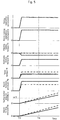
- Fig. 4 is a diagram showing behaviors of torque and the like at the time of a swing and boom raising operation in a case where boom load is absent (in the case where the bucket 35 is empty).
- a swing operation command "is” and a boom raising operation command “ib" are simultaneously inputted at time T3.
- the given condition is that the bottom pressure of the boom cylinder 32 is equal to the holding pressure of the excavator mechanism 30, and boom load is absent. Therefore, a load torque Te due to the swing electric motor 25 is not generated (not regenerated). Accordingly, the swing torque To generated by the swing hydraulic motor 27 becomes a total torque Tt of the swing electric motor 25 and the swing hydraulic motor 27. As a result, swing speed of the swing structure 20 increases gradually, so that angular velocity reaches ⁇ 1 at time T4 in this example.
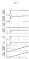
- Fig. 5 is a diagram showing behaviors of torque and the like at the time of a swing and boom raising operation in a case where a boom load is present (in a case where a load is present in the bucket 35).
- Broken lines in the diagram represent the torque and the like in the case where boom load is absent ( Fig. 4 ). It is assumed that the behaviors of the swing operation command "is” and the boom raising operation command "ib" are the same as in Fig. 4 .
- the swing speed in the example of Fig. 5 is suppressed by an amount of lowering in the rising speed of the boom 31. Therefore, although the speed is lowered in correspondence with the boom load, the excavator mechanism 30 is moved while describing a locus similar to that in the example of Fig. 4 .
- Fig. 6 is a block diagram of an essential part of a drive system provided in a construction machine according to a second embodiment of the present invention, and corresponds to Fig. 3 of the first embodiment.
- the same parts as in the first embodiment are denoted by the same reference symbols as in the preceding drawings, and descriptions of them are omitted.
- the boom cylinder 32 is provided with a stroke sensor 74e, and a signal from the stroke sensor 74e is outputted to the boom speed reduction amount calculation block 83a of the controller 80.
- Fig. 7 is a diagram showing behaviors of torque and the like at the time of a swing and boom raising operation in a case where boom load is absent (in a case where the bucket 35 is empty)
- Fig. 8 is a diagram showing behaviors of torque and the like at the time of a swing and boom raising operation in a case where a boom load is present (in a case where a load is present in the bucket 35).
- Fig. 9 is a block diagram of an essential part of a drive system provided in a construction machine according to a third embodiment of the present invention, and corresponds to Fig. 3 and Fig. 6 of the aforementioned embodiments.
- Fig. 9 the same parts as in the above-described embodiments are denoted by the same reference symbols as in the preceding drawings, and descriptions of them are omitted.
- the hydraulic excavator does not have a swing hydraulic motor 27, but is configured to drive and swing the swing structure 20 by only the swing electric motor 25. Therefore, in the control valve 42, a spool 61 corresponding to the swing hydraulic motor 27 and detectors 74bL and 74bR (see Fig. 3 for both) for detecting an operation pressure of the spool 61 are absent.
- a torque signal is inputted from the swing electric motor 25 to the swing torque calculation block 83c, and, in the swing torque calculation block 83c, a swing torque of the swing electric motor 25 is calculated based on the signal from the swing electric motor 25.
- regenerative drive of the swing electric motor 25 is not conducted at the time of giving swing power to the swing structure 20.
- power running drive of the swing electric motor 25 is performed constantly, independently of a boom load.
- a swing torque (torque correction amount ⁇ T) to be reduced for reducing the swing speed with respect to the reference swing speed Ss by a swing speed reduction amount ⁇ S calculated by the swing speed reduction amount calculation block 83b is calculated, a value obtained by subtracting the torque correction amount ⁇ T from a torque calculated by the swing torque calculation block 83c is generated, and the thus generated value is outputted to the power control unit 50.
- the present invention is also applicable to a hydraulic excavator in which a swing hydraulic motor 27 is omitted and swing drive is effected by only an electric motor 25 as in this embodiment.
- a configuration has been adopted in which a swing speed reduction amount ⁇ S according to a boom speed reduction amount ⁇ R is calculated and the swing torque is corrected thereby.
- a configuration in which a target swing torque is calculated based on a boom load and a swing operation amount, for example, in performing suppression of swing speed.
- relations between swing operation amount and swing torque are preset on the basis of boom load, and these relations are preliminarily stored in the torque command value calculation block 83d.
- signals from detectors 74a and 74d are inputted to the torque command value calculation block 83d.
- a swing torque as a target is calculated in the torque command value calculation block 83d on the basis of an operation amount of the swing lever system 72 and a boom load.
- the difference between a swing torque calculated by the swing torque calculation block 83c and a target value is calculated as a command value (load torque) for regenerative drive of the swing electric motor 25, and is outputted to the power control unit 50.
- a value obtained by correcting the swing torque calculated by the swing torque calculation block 83c on the basis of a target value is calculated as a command value for power running drive of the swing electric motor 25, and is outputted to the power control unit 50.
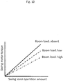
- Fig. 10 shows only three relation curves "boom load: absent,” “bool load: low” and “boom load: high,” the parameters of boom load are set more precisely, and the relation curves are present in the number corresponding to the number of settings of boom load.
- the swing speed reduction amount calculation block 83b In the swing speed reduction amount calculation block 83b,
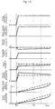
- Fig. 11 is a diagram for explaining the effect of the present invention.
- the axis of abscissas represents swing angle of the swing structure 20 from the start of swing at the time of a swing and boom raising operation
- the axis of ordinates represents a rising amount of the boom 31 from the start of boom raising at the time of a swing and boom raising operation.
- this is an example in which the boom 31 is raised at a reference boom raising speed Rs while performing swing drive at a reference swing speed Ss, and a line passing through position X0 and position X1 is made to be an example of reference locus (see alternate long and two short dashes line).
- the height of the boom 31 reaches D2 when time B (> A) elapses from the start of operation, but, in this case, the swing angle reaches A2 (> A1).
- the boom 31 reaches position X3 at height D2 along a locus that is lower than the reference locus (alternate long and two short dashes line). Therefore, if the swing and boom raising operation by the operator is intended to attain the reference locus, the locus passing through position X2 is an unexpectedly lower locus, so that the excavator mechanism 30 can possibly collide against the carrier of the transportation vehicle.
- the swing speed at the time of a swing and boom raising operation is suppressed in the case where a boom load is present, and, accordingly, the boom 31 is moved along the reference locus if the same operation is conducted. Since both the boom raising speed and the swing speed are lowered as compared to the case where boom load is absent, the boom is still at position X4 (height D1 ⁇ D2) when time A elapses, but the boom reaches position X1 after time B elapses from the start of operation.
- a power generation output can be obtained by performing regenerative drive of the swing electric motor 25 at the time of reducing the swing speed, and, accordingly, energy efficiency is enhanced.
- the present invention is applicable generally to construction machines including a work implement capable of being raised and lowered and a swing structure.
- the invention is also applicable to other construction machines such as crane vehicle having a crane (work implement) and a swing structure.
Landscapes
- Engineering & Computer Science (AREA)
- General Engineering & Computer Science (AREA)
- Mechanical Engineering (AREA)
- Mining & Mineral Resources (AREA)
- Civil Engineering (AREA)
- Structural Engineering (AREA)
- Physics & Mathematics (AREA)
- Fluid Mechanics (AREA)
- Chemical & Material Sciences (AREA)
- Analytical Chemistry (AREA)
- Operation Control Of Excavators (AREA)
- Fluid-Pressure Circuits (AREA)
Claims (5)
- Baumaschine, die Folgendes enthält:einen Kettenaufbau (10);einen Schwenkaufbau (20), der am Kettenaufbau (10) schwenkbar vorgesehen ist;einen Schwenkmotor (25, 27), der den Schwenkaufbau (20) antreibt und schwenkt;einen Ausleger (31), der mit dem Schwenkaufbau (20) verbunden ist;einen Auslegerzylinder (32), der den Ausleger (31) vertikal bewegt;ein Schwenkbetätigungssystem (72), das eine Schwenkbewegung des Schwenkaufbaus (20) anweist;ein Auslegerbetätigungssystem (78), das eine Vertikalbewegung des Auslegers (31) anweist;eine Detektionseinrichtung (74d, 74e), die eine Zustandsgröße, die entsprechend einer Last am Auslegerzylinder (32) variiert, detektiert; undeine Steuereinheit (80), die eine Schwenkgeschwindigkeit des Schwenkaufbaus (20) entsprechend einem Signal von der Detektionseinrichtung (74d, 74e) in Bezug auf eine Bezugsschwenkgeschwindigkeit entsprechend einem Signal von der Schwenkbetätigung verringert, während Signale von der Schwenkbetätigung durch das Schwenkbetätigungssystem (72) und einer Auslegerhebebetätigung durch das Auslegerbetätigungssystem (78) eingegeben werden,dadurch gekennzeichnet, dass die Steuereinheit (80) Folgendes enthält:einen Auslegergeschwindigkeits-Verringerungsberechnungsabschnitt (83a), der konfiguriert ist, einen Auslegergeschwindigkeits-Verringerungsbetrag ΔR in Bezug auf eine Bezugsauslegerhebegeschwindigkeit Rs, die an einen Betätigungsbetrag des Auslegerbetätigungssystems (78) auf der Grundlage des Signals von der Detektionseinrichtung (74d, 74e) angepasst ist, zu berechnen;einen Schwenkgeschwindigkeits-Verringerungsbetragsberechnungsabschnitt (83b), der konfiguriert ist, einen Schwenkgeschwindigkeits-Verringerungsbetrag ΔS in Bezug auf eine Bezugsschwenkgeschwindigkeit Ss, die an eine Betätigungsmenge des Schwenkbetätigungssystems (72) auf der Grundlage des Betätigungsbetrags des Schwenkbetätigungssystems (72) und des Auslegergeschwindigkeits-Verringerungsbetrags ΔR angepasst ist, zu berechnen; undeinen Drehmomentanweisungsberechnungsabschnitt (83d), der konfiguriert ist, eine Schwenkmotordrehmomentanweisung, um den Schwenkgeschwindigkeits-Verringerungsbetrag ΔS auf der Grundlage eines Schwenkdrehmoments des Schwenkmotors (25, 27) und des Schwenkgeschwindigkeits-Verringerungsbetrags ΔS zu erzeugen, zu berechnen und auszugeben, wobeider Schwenkgeschwindigkeits-Verringerungsbetragsberechnungsabschnitt (83b) den Schwenkgeschwindigkeits-Verringerungsbetrag ΔS derart berechnet, dass die Beziehung (Rs - ΔR)/(Ss - ΔS) = Rs/Ss erfüllt ist.
- Baumaschine nach Anspruch 1, wobei
der Schwenkmotor einen Hydraulikmotor (27) und einen Elektromotor (25) umfasst und
die Steuereinheit (80) entsprechend einem Detektionssignal der Detektionseinrichtung (74d, 74e) eine Leistungserzeugungslastanweisung zum Elektromotor (25) ausgibt. - Baumaschine nach Anspruch 1, wobei
der Schwenkmotor (25, 27) ein Elektromotor (25) ist und
die Steuereinheit (80) eine Drehzahl des Elektromotors (25) entsprechend einem Detektionssignal der Detektionseinrichtung (74d, 74e) steuert. - Baumaschine nach Anspruch 1, wobei
die Detektionseinrichtung ein Drucksensor (74d) ist, der einen Lastdruck am Auslegerzylinder (32) detektiert und
die Steuereinheit (80) eine Drehzahl des Schwenkmotors (25, 27) auf der Grundlage eines Auslegergeschwindigkeits-Verringerungsbetrags, der auf der Grundlage eines Signals vom Drucksensor (74d) berechnet wurde, steuert. - Baumaschine nach Anspruch 1, wobei
die Detektionseinrichtung ein Hubsensor (74e), der eine Schwankung im Hub des Auslegerzylinders (32) detektiert, ist und
die Steuereinheit (80) die Drehzahl des Schwenkmotors (25, 27) auf der Grundlage eines Auslegergeschwindigkeits-Verringerungsbetrags, der auf der Grundlage eines Signals vom Hubsensor (74e) berechnet wurde, steuert.
Applications Claiming Priority (2)
| Application Number | Priority Date | Filing Date | Title |
|---|---|---|---|
| JP2014031031A JP6150740B2 (ja) | 2014-02-20 | 2014-02-20 | 建設機械 |
| PCT/JP2015/050190 WO2015125503A1 (ja) | 2014-02-20 | 2015-01-06 | 建設機械 |
Publications (3)
| Publication Number | Publication Date |
|---|---|
| EP3109366A1 EP3109366A1 (de) | 2016-12-28 |
| EP3109366A4 EP3109366A4 (de) | 2017-11-01 |
| EP3109366B1 true EP3109366B1 (de) | 2018-12-12 |
Family
ID=53878019
Family Applications (1)
| Application Number | Title | Priority Date | Filing Date |
|---|---|---|---|
| EP15751923.2A Active EP3109366B1 (de) | 2014-02-20 | 2015-01-06 | Baumaschine |
Country Status (6)
| Country | Link |
|---|---|
| US (1) | US9863123B2 (de) |
| EP (1) | EP3109366B1 (de) |
| JP (1) | JP6150740B2 (de) |
| KR (1) | KR101747611B1 (de) |
| CN (1) | CN105473793B (de) |
| WO (1) | WO2015125503A1 (de) |
Families Citing this family (7)
| Publication number | Priority date | Publication date | Assignee | Title |
|---|---|---|---|---|
| CN113107045A (zh) * | 2015-12-28 | 2021-07-13 | 住友建机株式会社 | 挖土机以及挖土机用的控制装置和挖土机的控制方法 |
| WO2018051452A1 (ja) * | 2016-09-15 | 2018-03-22 | 日立建機株式会社 | ダンプトラックのピッチング制御システム |
| JP6630257B2 (ja) | 2016-09-30 | 2020-01-15 | 日立建機株式会社 | 建設機械 |
| WO2019146818A1 (en) * | 2018-01-26 | 2019-08-01 | Volvo Construction Equipment Ab | Safe swing system for excavator |
| US10801180B2 (en) * | 2018-06-11 | 2020-10-13 | Deere & Company | Work machine self protection system |
| JP7234891B2 (ja) * | 2019-09-30 | 2023-03-08 | コベルコ建機株式会社 | 作業機械 |
| CN119981184B (zh) * | 2025-03-05 | 2025-11-11 | 徐工集团工程机械股份有限公司科技分公司 | 降低装载机工作装置冲击的控制方法、装置及系统 |
Family Cites Families (16)
| Publication number | Priority date | Publication date | Assignee | Title |
|---|---|---|---|---|
| JPS59126829A (ja) * | 1983-01-10 | 1984-07-21 | Hitachi Constr Mach Co Ltd | 油圧シヨベルの油圧制御装置 |
| JPH072727Y2 (ja) * | 1986-06-03 | 1995-01-25 | 住友重機械工業株式会社 | 油圧シヨベルの油圧回路 |
| WO2004029435A1 (ja) * | 2002-09-26 | 2004-04-08 | Hitachi Construction Machinery Co., Ltd. | 建設機械の原動機制御装置 |
| EP2910690A1 (de) * | 2004-11-17 | 2015-08-26 | Komatsu Ltd. | Drehrichtungssteuerungsvorrichtung und Baumaschine |
| US8087240B2 (en) * | 2005-10-31 | 2012-01-03 | Komatsu Ltd. | Control apparatus for work machine |
| JP5125048B2 (ja) * | 2006-09-29 | 2013-01-23 | コベルコ建機株式会社 | 作業機械の旋回制御装置 |
| JP2008224039A (ja) | 2008-04-07 | 2008-09-25 | Komatsu Ltd | 油圧駆動機械の制御装置 |
| JP2011038298A (ja) * | 2009-08-10 | 2011-02-24 | Hitachi Constr Mach Co Ltd | 建設機械の油圧制御装置 |
| JP5341005B2 (ja) * | 2010-03-29 | 2013-11-13 | 日立建機株式会社 | 建設機械 |
| JP5356427B2 (ja) * | 2011-02-03 | 2013-12-04 | 日立建機株式会社 | ハイブリッド式建設機械 |
| JP5333511B2 (ja) * | 2011-05-02 | 2013-11-06 | コベルコ建機株式会社 | 旋回式作業機械 |
| EP2725151B1 (de) * | 2011-06-27 | 2016-08-03 | Sumitomo Heavy Industries, Ltd. | Hybridarbeitsmaschine und verfahren zu ihrer steuerung |
| JP5841399B2 (ja) * | 2011-10-14 | 2016-01-13 | 日立建機株式会社 | ハイブリッド式建設機械及びその制御方法 |
| JP5992886B2 (ja) * | 2013-08-30 | 2016-09-14 | 日立建機株式会社 | 作業機械 |
| JP6214327B2 (ja) * | 2013-10-18 | 2017-10-18 | 日立建機株式会社 | ハイブリッド式建設機械 |
| EP3085969B1 (de) * | 2013-12-20 | 2018-11-21 | Hitachi Construction Machinery Co., Ltd. | Baumaschine |
-
2014
- 2014-02-20 JP JP2014031031A patent/JP6150740B2/ja active Active
-
2015
- 2015-01-06 EP EP15751923.2A patent/EP3109366B1/de active Active
- 2015-01-06 WO PCT/JP2015/050190 patent/WO2015125503A1/ja not_active Ceased
- 2015-01-06 US US14/915,301 patent/US9863123B2/en not_active Expired - Fee Related
- 2015-01-06 CN CN201580001636.0A patent/CN105473793B/zh active Active
- 2015-01-06 KR KR1020167004091A patent/KR101747611B1/ko active Active
Non-Patent Citations (1)
| Title |
|---|
| None * |
Also Published As
| Publication number | Publication date |
|---|---|
| US9863123B2 (en) | 2018-01-09 |
| CN105473793A (zh) | 2016-04-06 |
| US20160348340A1 (en) | 2016-12-01 |
| KR101747611B1 (ko) | 2017-06-14 |
| EP3109366A4 (de) | 2017-11-01 |
| JP2015155615A (ja) | 2015-08-27 |
| EP3109366A1 (de) | 2016-12-28 |
| JP6150740B2 (ja) | 2017-06-21 |
| CN105473793B (zh) | 2017-07-14 |
| WO2015125503A1 (ja) | 2015-08-27 |
| KR20160033746A (ko) | 2016-03-28 |
Similar Documents
| Publication | Publication Date | Title |
|---|---|---|
| EP3109366B1 (de) | Baumaschine | |
| KR101834598B1 (ko) | 하이브리드식 건설 기계 | |
| EP3203089B1 (de) | Hydraulisches antriebssystem für arbeitsfahrzeug | |
| JP6291394B2 (ja) | 作業機械の油圧駆動システム | |
| EP3203087B1 (de) | Hydraulisches antriebssystem für arbeitsfahrzeug | |
| JP5873456B2 (ja) | 作業機械の駆動制御システム、それを備える作業機械、及びその駆動制御方法 | |
| WO2018061688A1 (ja) | 建設機械 | |
| CN110462225B (zh) | 作业机械 | |
| KR101747519B1 (ko) | 하이브리드식 건설 기계 | |
| EP2918733B1 (de) | Baumaschine | |
| JP6557472B2 (ja) | 作業機械の駆動制御システム、それを備える作業機械、及びその駆動制御方法 | |
| JP4990212B2 (ja) | 建設機械の電気・油圧駆動装置 | |
| JP6514895B2 (ja) | 作業機械の駆動制御システム、それを備える作業機械、及びその駆動制御方法 |
Legal Events
| Date | Code | Title | Description |
|---|---|---|---|
| PUAI | Public reference made under article 153(3) epc to a published international application that has entered the european phase |
Free format text: ORIGINAL CODE: 0009012 |
|
| STAA | Information on the status of an ep patent application or granted ep patent |
Free format text: STATUS: REQUEST FOR EXAMINATION WAS MADE |
|
| 17P | Request for examination filed |
Effective date: 20160304 |
|
| AK | Designated contracting states |
Kind code of ref document: A1 Designated state(s): AL AT BE BG CH CY CZ DE DK EE ES FI FR GB GR HR HU IE IS IT LI LT LU LV MC MK MT NL NO PL PT RO RS SE SI SK SM TR |
|
| AX | Request for extension of the european patent |
Extension state: BA ME |
|
| DAX | Request for extension of the european patent (deleted) | ||
| A4 | Supplementary search report drawn up and despatched |
Effective date: 20171005 |
|
| RIC1 | Information provided on ipc code assigned before grant |
Ipc: E02F 9/20 20060101AFI20170928BHEP Ipc: F15B 11/04 20060101ALI20170928BHEP Ipc: E02F 3/43 20060101ALI20170928BHEP Ipc: F15B 21/08 20060101ALI20170928BHEP Ipc: E02F 9/22 20060101ALI20170928BHEP Ipc: E02F 9/12 20060101ALI20170928BHEP |
|
| GRAP | Despatch of communication of intention to grant a patent |
Free format text: ORIGINAL CODE: EPIDOSNIGR1 |
|
| STAA | Information on the status of an ep patent application or granted ep patent |
Free format text: STATUS: GRANT OF PATENT IS INTENDED |
|
| INTG | Intention to grant announced |
Effective date: 20180731 |
|
| GRAS | Grant fee paid |
Free format text: ORIGINAL CODE: EPIDOSNIGR3 |
|
| GRAA | (expected) grant |
Free format text: ORIGINAL CODE: 0009210 |
|
| STAA | Information on the status of an ep patent application or granted ep patent |
Free format text: STATUS: THE PATENT HAS BEEN GRANTED |
|
| AK | Designated contracting states |
Kind code of ref document: B1 Designated state(s): AL AT BE BG CH CY CZ DE DK EE ES FI FR GB GR HR HU IE IS IT LI LT LU LV MC MK MT NL NO PL PT RO RS SE SI SK SM TR |
|
| REG | Reference to a national code |
Ref country code: GB Ref legal event code: FG4D |
|
| REG | Reference to a national code |
Ref country code: CH Ref legal event code: EP |
|
| REG | Reference to a national code |
Ref country code: AT Ref legal event code: REF Ref document number: 1076147 Country of ref document: AT Kind code of ref document: T Effective date: 20181215 |
|
| REG | Reference to a national code |
Ref country code: DE Ref legal event code: R096 Ref document number: 602015021375 Country of ref document: DE |
|
| REG | Reference to a national code |
Ref country code: IE Ref legal event code: FG4D |
|
| REG | Reference to a national code |
Ref country code: NL Ref legal event code: MP Effective date: 20181212 |
|
| REG | Reference to a national code |
Ref country code: LT Ref legal event code: MG4D |
|
| PG25 | Lapsed in a contracting state [announced via postgrant information from national office to epo] |
Ref country code: ES Free format text: LAPSE BECAUSE OF FAILURE TO SUBMIT A TRANSLATION OF THE DESCRIPTION OR TO PAY THE FEE WITHIN THE PRESCRIBED TIME-LIMIT Effective date: 20181212 Ref country code: BG Free format text: LAPSE BECAUSE OF FAILURE TO SUBMIT A TRANSLATION OF THE DESCRIPTION OR TO PAY THE FEE WITHIN THE PRESCRIBED TIME-LIMIT Effective date: 20190312 Ref country code: NO Free format text: LAPSE BECAUSE OF FAILURE TO SUBMIT A TRANSLATION OF THE DESCRIPTION OR TO PAY THE FEE WITHIN THE PRESCRIBED TIME-LIMIT Effective date: 20190312 Ref country code: LT Free format text: LAPSE BECAUSE OF FAILURE TO SUBMIT A TRANSLATION OF THE DESCRIPTION OR TO PAY THE FEE WITHIN THE PRESCRIBED TIME-LIMIT Effective date: 20181212 Ref country code: HR Free format text: LAPSE BECAUSE OF FAILURE TO SUBMIT A TRANSLATION OF THE DESCRIPTION OR TO PAY THE FEE WITHIN THE PRESCRIBED TIME-LIMIT Effective date: 20181212 Ref country code: LV Free format text: LAPSE BECAUSE OF FAILURE TO SUBMIT A TRANSLATION OF THE DESCRIPTION OR TO PAY THE FEE WITHIN THE PRESCRIBED TIME-LIMIT Effective date: 20181212 Ref country code: FI Free format text: LAPSE BECAUSE OF FAILURE TO SUBMIT A TRANSLATION OF THE DESCRIPTION OR TO PAY THE FEE WITHIN THE PRESCRIBED TIME-LIMIT Effective date: 20181212 |
|
| REG | Reference to a national code |
Ref country code: AT Ref legal event code: MK05 Ref document number: 1076147 Country of ref document: AT Kind code of ref document: T Effective date: 20181212 |
|
| PG25 | Lapsed in a contracting state [announced via postgrant information from national office to epo] |
Ref country code: SE Free format text: LAPSE BECAUSE OF FAILURE TO SUBMIT A TRANSLATION OF THE DESCRIPTION OR TO PAY THE FEE WITHIN THE PRESCRIBED TIME-LIMIT Effective date: 20181212 Ref country code: RS Free format text: LAPSE BECAUSE OF FAILURE TO SUBMIT A TRANSLATION OF THE DESCRIPTION OR TO PAY THE FEE WITHIN THE PRESCRIBED TIME-LIMIT Effective date: 20181212 Ref country code: AL Free format text: LAPSE BECAUSE OF FAILURE TO SUBMIT A TRANSLATION OF THE DESCRIPTION OR TO PAY THE FEE WITHIN THE PRESCRIBED TIME-LIMIT Effective date: 20181212 Ref country code: GR Free format text: LAPSE BECAUSE OF FAILURE TO SUBMIT A TRANSLATION OF THE DESCRIPTION OR TO PAY THE FEE WITHIN THE PRESCRIBED TIME-LIMIT Effective date: 20190313 |
|
| PG25 | Lapsed in a contracting state [announced via postgrant information from national office to epo] |
Ref country code: NL Free format text: LAPSE BECAUSE OF FAILURE TO SUBMIT A TRANSLATION OF THE DESCRIPTION OR TO PAY THE FEE WITHIN THE PRESCRIBED TIME-LIMIT Effective date: 20181212 |
|
| PG25 | Lapsed in a contracting state [announced via postgrant information from national office to epo] |
Ref country code: PL Free format text: LAPSE BECAUSE OF FAILURE TO SUBMIT A TRANSLATION OF THE DESCRIPTION OR TO PAY THE FEE WITHIN THE PRESCRIBED TIME-LIMIT Effective date: 20181212 Ref country code: IT Free format text: LAPSE BECAUSE OF FAILURE TO SUBMIT A TRANSLATION OF THE DESCRIPTION OR TO PAY THE FEE WITHIN THE PRESCRIBED TIME-LIMIT Effective date: 20181212 Ref country code: PT Free format text: LAPSE BECAUSE OF FAILURE TO SUBMIT A TRANSLATION OF THE DESCRIPTION OR TO PAY THE FEE WITHIN THE PRESCRIBED TIME-LIMIT Effective date: 20190412 Ref country code: CZ Free format text: LAPSE BECAUSE OF FAILURE TO SUBMIT A TRANSLATION OF THE DESCRIPTION OR TO PAY THE FEE WITHIN THE PRESCRIBED TIME-LIMIT Effective date: 20181212 |
|
| PG25 | Lapsed in a contracting state [announced via postgrant information from national office to epo] |
Ref country code: IS Free format text: LAPSE BECAUSE OF FAILURE TO SUBMIT A TRANSLATION OF THE DESCRIPTION OR TO PAY THE FEE WITHIN THE PRESCRIBED TIME-LIMIT Effective date: 20190412 Ref country code: SK Free format text: LAPSE BECAUSE OF FAILURE TO SUBMIT A TRANSLATION OF THE DESCRIPTION OR TO PAY THE FEE WITHIN THE PRESCRIBED TIME-LIMIT Effective date: 20181212 Ref country code: SM Free format text: LAPSE BECAUSE OF FAILURE TO SUBMIT A TRANSLATION OF THE DESCRIPTION OR TO PAY THE FEE WITHIN THE PRESCRIBED TIME-LIMIT Effective date: 20181212 Ref country code: EE Free format text: LAPSE BECAUSE OF FAILURE TO SUBMIT A TRANSLATION OF THE DESCRIPTION OR TO PAY THE FEE WITHIN THE PRESCRIBED TIME-LIMIT Effective date: 20181212 Ref country code: RO Free format text: LAPSE BECAUSE OF FAILURE TO SUBMIT A TRANSLATION OF THE DESCRIPTION OR TO PAY THE FEE WITHIN THE PRESCRIBED TIME-LIMIT Effective date: 20181212 |
|
| REG | Reference to a national code |
Ref country code: CH Ref legal event code: PL |
|
| REG | Reference to a national code |
Ref country code: DE Ref legal event code: R097 Ref document number: 602015021375 Country of ref document: DE |
|
| PG25 | Lapsed in a contracting state [announced via postgrant information from national office to epo] |
Ref country code: LU Free format text: LAPSE BECAUSE OF NON-PAYMENT OF DUE FEES Effective date: 20190106 |
|
| REG | Reference to a national code |
Ref country code: BE Ref legal event code: MM Effective date: 20190131 |
|
| PLBE | No opposition filed within time limit |
Free format text: ORIGINAL CODE: 0009261 |
|
| STAA | Information on the status of an ep patent application or granted ep patent |
Free format text: STATUS: NO OPPOSITION FILED WITHIN TIME LIMIT |
|
| REG | Reference to a national code |
Ref country code: IE Ref legal event code: MM4A |
|
| PG25 | Lapsed in a contracting state [announced via postgrant information from national office to epo] |
Ref country code: SI Free format text: LAPSE BECAUSE OF FAILURE TO SUBMIT A TRANSLATION OF THE DESCRIPTION OR TO PAY THE FEE WITHIN THE PRESCRIBED TIME-LIMIT Effective date: 20181212 Ref country code: AT Free format text: LAPSE BECAUSE OF FAILURE TO SUBMIT A TRANSLATION OF THE DESCRIPTION OR TO PAY THE FEE WITHIN THE PRESCRIBED TIME-LIMIT Effective date: 20181212 Ref country code: DK Free format text: LAPSE BECAUSE OF FAILURE TO SUBMIT A TRANSLATION OF THE DESCRIPTION OR TO PAY THE FEE WITHIN THE PRESCRIBED TIME-LIMIT Effective date: 20181212 Ref country code: MC Free format text: LAPSE BECAUSE OF FAILURE TO SUBMIT A TRANSLATION OF THE DESCRIPTION OR TO PAY THE FEE WITHIN THE PRESCRIBED TIME-LIMIT Effective date: 20181212 |
|
| 26N | No opposition filed |
Effective date: 20190913 |
|
| GBPC | Gb: european patent ceased through non-payment of renewal fee |
Effective date: 20190312 |
|
| PG25 | Lapsed in a contracting state [announced via postgrant information from national office to epo] |
Ref country code: BE Free format text: LAPSE BECAUSE OF NON-PAYMENT OF DUE FEES Effective date: 20190131 |
|
| PG25 | Lapsed in a contracting state [announced via postgrant information from national office to epo] |
Ref country code: CH Free format text: LAPSE BECAUSE OF NON-PAYMENT OF DUE FEES Effective date: 20190131 Ref country code: LI Free format text: LAPSE BECAUSE OF NON-PAYMENT OF DUE FEES Effective date: 20190131 |
|
| PG25 | Lapsed in a contracting state [announced via postgrant information from national office to epo] |
Ref country code: IE Free format text: LAPSE BECAUSE OF NON-PAYMENT OF DUE FEES Effective date: 20190106 Ref country code: GB Free format text: LAPSE BECAUSE OF NON-PAYMENT OF DUE FEES Effective date: 20190312 |
|
| PG25 | Lapsed in a contracting state [announced via postgrant information from national office to epo] |
Ref country code: FR Free format text: LAPSE BECAUSE OF NON-PAYMENT OF DUE FEES Effective date: 20190212 |
|
| PG25 | Lapsed in a contracting state [announced via postgrant information from national office to epo] |
Ref country code: TR Free format text: LAPSE BECAUSE OF FAILURE TO SUBMIT A TRANSLATION OF THE DESCRIPTION OR TO PAY THE FEE WITHIN THE PRESCRIBED TIME-LIMIT Effective date: 20181212 |
|
| PG25 | Lapsed in a contracting state [announced via postgrant information from national office to epo] |
Ref country code: MT Free format text: LAPSE BECAUSE OF NON-PAYMENT OF DUE FEES Effective date: 20190106 |
|
| PG25 | Lapsed in a contracting state [announced via postgrant information from national office to epo] |
Ref country code: CY Free format text: LAPSE BECAUSE OF FAILURE TO SUBMIT A TRANSLATION OF THE DESCRIPTION OR TO PAY THE FEE WITHIN THE PRESCRIBED TIME-LIMIT Effective date: 20181212 |
|
| PG25 | Lapsed in a contracting state [announced via postgrant information from national office to epo] |
Ref country code: HU Free format text: LAPSE BECAUSE OF FAILURE TO SUBMIT A TRANSLATION OF THE DESCRIPTION OR TO PAY THE FEE WITHIN THE PRESCRIBED TIME-LIMIT; INVALID AB INITIO Effective date: 20150106 |
|
| PG25 | Lapsed in a contracting state [announced via postgrant information from national office to epo] |
Ref country code: MK Free format text: LAPSE BECAUSE OF FAILURE TO SUBMIT A TRANSLATION OF THE DESCRIPTION OR TO PAY THE FEE WITHIN THE PRESCRIBED TIME-LIMIT Effective date: 20181212 |
|
| PGFP | Annual fee paid to national office [announced via postgrant information from national office to epo] |
Ref country code: DE Payment date: 20251203 Year of fee payment: 12 |