EP3109436B1 - Gasturbine mit zwischengekühlter kühlluft mit verbessertem luftstrom - Google Patents
Gasturbine mit zwischengekühlter kühlluft mit verbessertem luftstrom Download PDFInfo
- Publication number
- EP3109436B1 EP3109436B1 EP16175533.5A EP16175533A EP3109436B1 EP 3109436 B1 EP3109436 B1 EP 3109436B1 EP 16175533 A EP16175533 A EP 16175533A EP 3109436 B1 EP3109436 B1 EP 3109436B1
- Authority
- EP
- European Patent Office
- Prior art keywords
- air
- compressor
- gas turbine
- high pressure
- turbine engine
- Prior art date
- Legal status (The legal status is an assumption and is not a legal conclusion. Google has not performed a legal analysis and makes no representation as to the accuracy of the status listed.)
- Active
Links
Images


Classifications
-
- F—MECHANICAL ENGINEERING; LIGHTING; HEATING; WEAPONS; BLASTING
- F02—COMBUSTION ENGINES; HOT-GAS OR COMBUSTION-PRODUCT ENGINE PLANTS
- F02C—GAS-TURBINE PLANTS; AIR INTAKES FOR JET-PROPULSION PLANTS; CONTROLLING FUEL SUPPLY IN AIR-BREATHING JET-PROPULSION PLANTS
- F02C7/00—Features, components parts, details or accessories, not provided for in, or of interest apart form groups F02C1/00 - F02C6/00; Air intakes for jet-propulsion plants
- F02C7/12—Cooling of plants
- F02C7/16—Cooling of plants characterised by cooling medium
- F02C7/18—Cooling of plants characterised by cooling medium the medium being gaseous, e.g. air
- F02C7/185—Cooling means for reducing the temperature of the cooling air or gas
-
- F—MECHANICAL ENGINEERING; LIGHTING; HEATING; WEAPONS; BLASTING
- F05—INDEXING SCHEMES RELATING TO ENGINES OR PUMPS IN VARIOUS SUBCLASSES OF CLASSES F01-F04
- F05D—INDEXING SCHEME FOR ASPECTS RELATING TO NON-POSITIVE-DISPLACEMENT MACHINES OR ENGINES, GAS-TURBINES OR JET-PROPULSION PLANTS
- F05D2260/00—Function
- F05D2260/20—Heat transfer, e.g. cooling
- F05D2260/213—Heat transfer, e.g. cooling by the provision of a heat exchanger within the cooling circuit
-
- Y—GENERAL TAGGING OF NEW TECHNOLOGICAL DEVELOPMENTS; GENERAL TAGGING OF CROSS-SECTIONAL TECHNOLOGIES SPANNING OVER SEVERAL SECTIONS OF THE IPC; TECHNICAL SUBJECTS COVERED BY FORMER USPC CROSS-REFERENCE ART COLLECTIONS [XRACs] AND DIGESTS
- Y02—TECHNOLOGIES OR APPLICATIONS FOR MITIGATION OR ADAPTATION AGAINST CLIMATE CHANGE
- Y02T—CLIMATE CHANGE MITIGATION TECHNOLOGIES RELATED TO TRANSPORTATION
- Y02T50/00—Aeronautics or air transport
- Y02T50/60—Efficient propulsion technologies, e.g. for aircraft
Definitions
- This application relates to improvements in providing cooling air from a compressor section to a turbine section in a gas turbine engine.
- Gas turbine engines typically include a fan delivering air into a bypass duct as propulsion air. Further, the fan delivers air into a compressor section where it is compressed. The compressed air passes into a combustion section where it is mixed with fuel and ignited. Products of this combustion pass downstream over turbine rotors driving them to rotate.
- US 5,724,806 relates to a system for cooling hot section components of a gas turbine engine.
- US 2009/0196736 relates to cooling and/or sealing a gas turbine.
- US 2012/210723 A1 relates to a gas turbine generator set.
- a gas turbine engine according to claim 1 is provided.
- air is also tapped from the downstream discharge of the high pressure compressor and mixed with air in the downstream connection before the mixed air is delivered to the upstream location in the high pressure turbine.
- the upstream location in the high pressure turbine is a first stage of the high pressure turbine.
- a main fan delivers bypass air into a bypass duct and into a heat exchanger which is positioned within the bypass duct to be cooled by bypass air.
- the cooling compressor includes a centrifugal compressor impeller.
- the turbine section drives a bull gear, the gear further driving an impeller of the cooling compressor.
- the bull gear also drives an accessory gearbox.
- a gear ratio multiplier is included such that the impeller rotates at a faster speed than the tower shaft.
- the impeller is a centrifugal compressor impeller.
- an auxiliary fan is positioned upstream of the heat exchanger.
- the auxiliary fan operates at a variable speed.
- air temperatures at the downstream most location of the high pressure compressor are greater than or equal to 732.2 °C (1350°F).
- FIG. 1 schematically illustrates an example gas turbine engine 20 that includes a fan section 22, a compressor section 24, a combustor section 26 and a turbine section 28.
- Alternative engines might include an augmenter section (not shown) among other systems or features.
- the fan section 22 drives air along a bypass flow path B while the compressor section 24 draws air in along a core flow path C where air is compressed and communicated to a combustor section 26.
- air is mixed with fuel and ignited to generate a high pressure exhaust gas stream that expands through the turbine section 28 where energy is extracted and utilized to drive the fan section 22 and the compressor section 24.
- turbofan gas turbine engine depicts a turbofan gas turbine engine
- the concepts described herein are not limited to use with turbofans as the teachings may be applied to other types of turbine engines; for example a turbine engine including a three-spool architecture in which three spools concentrically rotate about a common axis and where a low spool enables a low pressure turbine to drive a fan via a gearbox, an intermediate spool that enables an intermediate pressure turbine to drive a first compressor of the compressor section, and a high spool that enables a high pressure turbine to drive a high pressure compressor of the compressor section.
- the example engine 20 generally includes a low speed spool 30 and a high speed spool 32 mounted for rotation about an engine central longitudinal axis A relative to an engine static structure 36 via several bearing systems 38. It should be understood that various bearing systems 38 at various locations may alternatively or additionally be provided.
- the low speed spool 30 generally includes an inner shaft 40 that connects a fan 42 and a low pressure (or first) compressor section 44 to a low pressure (or first) turbine section 46.
- the inner shaft 40 drives the fan 42 through a speed change device, such as a geared architecture 48, to drive the fan 42 at a lower speed than the low speed spool 30.
- the high-speed spool 32 includes an outer shaft 50 that interconnects a high pressure (or second) compressor section 52 and a high pressure (or second) turbine section 54.
- the inner shaft 40 and the outer shaft 50 are concentric and rotate via the bearing systems 38 about the engine central longitudinal axis A.
- a combustor 56 is arranged between the high pressure compressor 52 and the high pressure turbine 54.
- the high pressure turbine 54 includes at least two stages to provide a double stage high pressure turbine 54.
- the high pressure turbine 54 includes only a single stage.
- a "high pressure" compressor or turbine experiences a higher pressure than a corresponding "low pressure” compressor or turbine.
- the example low pressure turbine 46 has a pressure ratio that is greater than about 5.
- the pressure ratio of the example low pressure turbine 46 is measured prior to an inlet of the low pressure turbine 46 as related to the pressure measured at the outlet of the low pressure turbine 46 prior to an exhaust nozzle.
- a mid-turbine frame 58 of the engine static structure 36 is arranged generally between the high pressure turbine 54 and the low pressure turbine 46.
- the mid-turbine frame 58 further supports bearing systems 38 in the turbine section 28 as well as setting airflow entering the low pressure turbine 46.
- Airflow through the core airflow path C is compressed by the low pressure compressor 44 then by the high pressure compressor 52 mixed with fuel and ignited in the combustor 56 to produce high speed exhaust gases that are then expanded through the high pressure turbine 54 and low pressure turbine 46.
- the mid-turbine frame 58 includes vanes 60, which are in the core airflow path and function as an inlet guide vane for the low pressure turbine 46. Utilizing the vane 60 of the mid-turbine frame 58 as the inlet guide vane for low pressure turbine 46 decreases the length of the low pressure turbine 46 without increasing the axial length of the mid-turbine frame 58. Reducing or eliminating the number of vanes in the low pressure turbine 46 shortens the axial length of the turbine section 28. Thus, the compactness of the gas turbine engine 20 is increased and a higher power density may be achieved.
- the disclosed gas turbine engine 20 in one example is a high-bypass geared aircraft engine.
- the gas turbine engine 20 includes a bypass ratio greater than about six (6), with an example embodiment being greater than about ten (10).
- the example geared architecture 48 is an epicyclical gear train, such as a planetary gear system, star gear system or other known gear system, with a gear reduction ratio of greater than 2.3.
- the gas turbine engine 20 includes a bypass ratio greater than ten (10:1) and the fan diameter is significantly larger than an outer diameter of the low pressure compressor 44. It should be understood, however, that the above parameters are only exemplary of one embodiment of a gas turbine engine including a geared architecture and that the present disclosure is applicable to other gas turbine engines.
- the fan section 22 of the engine 20 is designed for a particular flight condition -- typically cruise at about 0.8 Mach and about 10.7 km (35,000 feet).
- the flight condition of 0.8 Mach and 10.7 km (35,000 ft.), with the engine at its best fuel consumption - also known as "bucket cruise Thrust Specific Fuel Consumption ('TSFC')" - is the industry standard parameter of kg-mass (pound-mass (lbm)) of fuel per hour being burned divided by kg-force (pound-force (1bf)) of thrust the engine produces at that minimum point.
- Low fan pressure ratio is the pressure ratio across the fan blade alone, without a Fan Exit Guide Vane (“FEGV”) system.
- the low fan pressure ratio as disclosed herein according to one non-limiting embodiment is less than about 1.50. In another non-limiting embodiment the low fan pressure ratio is less than 1.45.
- Low corrected fan tip speed is the actual fan tip speed in ft/sec divided by an industry standard temperature correction of [(Tram °R)/(518.7°R)] 0.5 .
- the "Low corrected fan tip speed”, as disclosed herein according to one non-limiting embodiment, is less than 350.5 m/second (1150 ft/second).
- the example gas turbine engine includes the fan 42 that comprises in one non-limiting embodiment less than about 26 fan blades. In another non-limiting embodiment, the fan section 22 includes less than about 20 fan blades. Moreover, in one disclosed embodiment the low pressure turbine 46 includes no more than about 6 turbine rotors schematically indicated at 34. In another non-limiting example embodiment the low pressure turbine 46 includes about 3 turbine rotors. A ratio between the number of fan blades 42 and the number of low pressure turbine rotors is between about 3.3 and about 8.6. The example low pressure turbine 46 provides the driving power to rotate the fan section 22 and therefore the relationship between the number of turbine rotors 34 in the low pressure turbine 46 and the number of blades 42 in the fan section 22 disclose an example gas turbine engine 20 with increased power transfer efficiency.
- Gas turbine engines designs are seeking to increase overall efficiency by generating higher overall pressure ratios. By achieving higher overall pressure ratios, increased levels of performance and efficiency may be achieved. However, challenges are raised in that the parts and components associated with a high pressure turbine require additional cooling air as the overall pressure ratio increases.
- the example engine 20 utilizes air bleed 80 from an upstream portion of the compressor section 24 for use in cooling portions of the turbine section 28.
- the air bleed is from a location upstream of the discharge 82 of the compressor section 24.
- the bleed air passes through a heat exchanger 84 to further cool the cooling air provided to the turbine section 28.
- the air passing through heat exchanger 84 is cooled by the bypass air B. That is, heat exchanger 84 is positioned in the path of bypass air B.
- FIG. 2 A prior art approach to providing cooling air is illustrated in Figure 2 .
- An engine 90 incorporates a high pressure compressor 92 downstream of the low pressure compressor 94.
- a fan 96 delivers air into a bypass duct 98 and into the low pressure compressor 94.
- a downstream most point, or discharge 82 of the high pressure compressor 92 provides bleed air into a heat exchanger 93.
- the heat exchanger is in the path of the bypass air in bypass duct 98, and is cooled. This high pressure high temperature air from location 82 is delivered into a high pressure turbine 102.
- the downstream most point 82 of the high pressure compressor 82 is known as station 3.
- the temperature T3 and pressure P3 are both very high.
- T3 levels are expected to approach greater than or equal to 732.2°C (1350°F).
- Current heat exchanger technology is becoming a limiting factor as they are made of materials, manufacturing, and design capability which have difficulty receiving such high temperature and pressure levels.
- FIG. 3 shows an engine 100 coming which is not part of the invention.
- a fan 104 may deliver air B into a bypass duct 105 and into a low pressure compressor 106.
- High pressure compressor 108 is positioned downstream of the low pressure compressor 106.
- a bleed 110 taps air from a location upstream of the downstream most end 82 of the high pressure compressor 108. This air is at temperatures and pressures which are much lower than T3/P3.
- the air tapped at 110 passes through a heat exchanger 112 which sits in the bypass duct 105 receiving air B. Further, the air from the heat exchanger 112 passes through a compressor 114, and then into a conduit 115 leading to a high turbine 117. This structure is all shown schematically.
- An auxiliary fan 116 may be positioned upstream of the heat exchanger 112 as illustrated.
- the main fan 104 may not provide sufficient pressure to drive sufficient air across the heat exchanger 112.
- the auxiliary fan will ensure there is adequate air flow in the circumferential location of the heat exchanger 112.
- the auxiliary fan may be variable speed, with the speed of the fan varied to control the temperature of the air downstream of the heat exchanger 112.
- the speed of the auxiliary fan may be varied based upon the operating power of the overall engine.
- a temperature/entropy diagram illustrates that a lower level of energy is spent to compress air of a lower temperature to the desired P3 pressure level. Cooler air requires less work to compress when compared to warmer air. Accordingly, the work required to raise the pressure of the air drawn from an early stage of the compressor section is less than if the air were compressed to the desired pressure within the compressor section. Therefore, high pressure air at P3 levels or higher can be obtained at significantly lower temperatures than T3.
- the prior system would move from point 2 to point 3, with a dramatic increase in temperature.
- the disclosed or new system moves from point 2 to point 5 through the heat exchanger, and the cooling compressor then compresses the air up to point 6. As can be appreciated, point 6 is at a much lower temperature.
- FIG. 5 shows a detail of compressor 114 having an outlet into conduit 115.
- a primary tower shaft 120 drives an accessory gearbox 121.
- the shaft 126 drives a compressor rotor within the compressor 114.
- the shafts 120 and 126 may be driven by a bull gear 125 that is driven by a turbine rotor. In one example, it also rotates with a high pressure compressor rotor.
- Figure 6 shows an example wherein a gear 128 is driven by the shaft 126 to, in turn, drive a gear 130 which drives a compressor impeller 129.
- An input 132 to the compressor impeller 129 supplies the air from the tap 110. The air is compressed and delivered into the outlet conduit 115.
- the compressor impeller may be driven to operate an optimum speed.
- the gear ratio increase may be in a range of 5:1 - 8:1, and in one example, 6.1.
- the system as described above has many benefits. Once the air has passed through the compressor 114, it will have been compressed to a very high pressure. This pressure is beneficial for delivery to the first stage of a high pressure turbine. However, further downstream within the high pressure turbine, the higher pressure for the cooling air is not necessary. If air is delivered to those downstream stages, then there may be efficiency losses as it would not be necessary to compress that air to such a high degree.
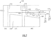
- An engine embodiment 150 is shown in Figure 7 .
- a fan 152 delivers air into a bypass duct 154, and across the heat exchanger 156, as in the prior embodiments.
- Low pressure compressor 158 is associated with a tap 160 which passes through the heat exchanger 156. That air then passes to an auxiliary compressor 162 which has a discharge delivering the air to a discharge duct 164.
- Discharge duct 164 is delivered to an upstream location 166 within a high pressure turbine. This may be the first stage of the high pressure turbine.
- An intermediate pressure tap 172 within the compressor 162 taps air through a mixer 174, and to a downstream cooling location 176. Downstream cooling location may be a second stage, or even further downstream in the high pressure turbine.
- the air at tap 172 has not been compressed to its full extent, and the losses mentioned above are not experienced.
- the mixer 174 may receive air from line 171 to mix with the air tapped from the intermediate pressure tap 172.
Landscapes
- Engineering & Computer Science (AREA)
- Chemical & Material Sciences (AREA)
- Combustion & Propulsion (AREA)
- Mechanical Engineering (AREA)
- General Engineering & Computer Science (AREA)
- Structures Of Non-Positive Displacement Pumps (AREA)
Claims (13)
- Gasturbinentriebwerk, umfassend:einen Hauptkompressorabschnitt, der einen Hochdrucckompressor mit einem stromabwärtigen Ausgang und mehreren stromaufwärtige Stellen aufweist;einen Turbinenabschnitt, der eine Hochdruckturbine (117) aufweist;ein Ladeluftkühlungssystem, wobei das Ladeluftkühlungssystem ferner Folgendes umfasst:einen Wärmetauscher (156) zum Kühlen von Luft, die bei einer ersten Temperatur und einem ersten Druck aus einem Teil des Hauptkompressorabschnitts gezogen wird, um die Luft auf eine zweite Temperatur zu kühlen, die kühler ist als die erste Temperatur;einen Kühlkompressor (162), der Luft, die aus dem Wärmetauscher übertragen wird, auf einen zweiten Druck komprimiert, der höher ist als der erste Druck, und um die komprimierte Luft an einen Teil des Turbinenabschnitts zu übertragen; undwobei der Kühlkompressor eine stromabwärtige Verbindung beinhaltet, um Ausgangsdruckluft an eine stromaufwärtige Stelle in der Hochdruckturbine zu liefern, und dadurch gekennzeichnet, dass der Kühlkompressor ferner einen zweiten Durchlass (172) umfasst, der aus einer dazwischenliegenden Druckstelle innerhalb des Kühlkompressors (162) kommt, undden zweiten Durchlass, um mit einer stromabwärtigen Stelle innerhalb der Hochdruckturbine verbunden zu sein.
- Gasturbinentriebwerk nach Anspruch 1, wobei Luft auch aus dem stromabwärtigen Ausgang des Hochdruckkompressors abgezapft und mit Luft in der stromabwärtigen Verbindung vermischt wird, bevor die vermischte Luft an die stromaufwärtige Stelle in der Hochdruckturbine geliefert wird.
- Gasturbinentriebwerk nach Anspruch 1 oder 2, wobei ein Zusatzlüfter (116) stromaufwärts von dem Wärmetauscher positioniert ist.
- Gasturbinentriebwerk nach einem der Ansprüche 1-3, wobei ein Antriebszahnrad (125) ein Laufrad (129) des Kühlkompressors antreibt, und vorzugsweise wobei das Antriebszahnrad (125) auch ein Hilfsaggregatsgetriebe (121) antreibt.
- Gasturbinentriebwerk nach Anspruch 1, wobei Luft auch aus dem stromabwärtigen Ausgang des Hochdruckkompressors abgezapft und mit Luft in der stromabwärtigen Verbindung vermischt wird, bevor die vermischte Luft an die stromaufwärtige Stelle in der Hochdruckturbine geliefert wird.
- Gasturbinentriebwerk nach Anspruch 5, wobei die stromaufwärtige Stelle in der Hochdruckturbine (117) eine erste Stufe der Hochdruckturbine ist.
- Gasturbinentriebwerk nach Anspruch 5 oder 6, wobei ein Hauptlüfter (104) Umgehungsluft in einen Umgehungskanal und in den Wärmetauscher (112) liefert, der in dem Umgehungskanal positioniert ist, um von Umgehungsluft gekühlt zu werden.
- Gasturbinentriebwerk nach einem der Ansprüche 5-7, wobei der Kühlkompressor ein zentrifugales Kompressorlaufrad beinhaltet.
- Gasturbinentriebwerk nach einem der Ansprüche 5-8, wobei der Turbinenabschnitt ein Antriebszahnrad (125) antreibt, wobei das Antriebszahnrad ferner ein Laufrad (129) des Kühlkompressors antreibt.
- Gasturbinentriebwerk nach Anspruch 9, wobei das Antriebszahnrad (125) auch ein Hilfsaggregatsgetriebe (121) antreibt, und vorzugsweise wobei ein Übersetzungsverhältnismultiplikator so beinhaltet ist, dass das Laufrad (129) mit einer höheren Geschwindigkeit rotiert als die Turmwelle (120).
- Gasturbinentriebwerk nach Anspruch 9, wobei das Laufrad (129) ein zentrifugales Kompressorlaufrad ist, und vorzugsweise wobei ein Zusatzlüfter (116) stromaufwärts von dem Wärmetauscher positioniert ist.
- Gasturbinentriebwerk nach einem der Ansprüche 1 oder 5-11, wobei ein Zusatzlüfter (116) stromaufwärts von dem Wärmetauscher positioniert ist, und vorzugsweise wobei der Zusatzlüfter (116) mit verschiedenen Geschwindigkeiten betrieben wird.
- Gasturbinentriebwerk nach einem der Ansprüche 1 oder 5-12, wobei Lufttemperaturen an der stromabwärtigsten Stelle des Hochdruckkompressors 732,2 °C (1350 °F) oder mehr betragen.
Applications Claiming Priority (1)
| Application Number | Priority Date | Filing Date | Title |
|---|---|---|---|
| US14/745,564 US9856793B2 (en) | 2015-02-12 | 2015-06-22 | Intercooled cooling air with improved air flow |
Publications (2)
| Publication Number | Publication Date |
|---|---|
| EP3109436A1 EP3109436A1 (de) | 2016-12-28 |
| EP3109436B1 true EP3109436B1 (de) | 2020-02-26 |
Family
ID=56263524
Family Applications (1)
| Application Number | Title | Priority Date | Filing Date |
|---|---|---|---|
| EP16175533.5A Active EP3109436B1 (de) | 2015-06-22 | 2016-06-21 | Gasturbine mit zwischengekühlter kühlluft mit verbessertem luftstrom |
Country Status (1)
| Country | Link |
|---|---|
| EP (1) | EP3109436B1 (de) |
Families Citing this family (1)
| Publication number | Priority date | Publication date | Assignee | Title |
|---|---|---|---|---|
| US10738703B2 (en) | 2018-03-22 | 2020-08-11 | Raytheon Technologies Corporation | Intercooled cooling air with combined features |
Citations (1)
| Publication number | Priority date | Publication date | Assignee | Title |
|---|---|---|---|---|
| US20120210723A1 (en) * | 2009-09-03 | 2012-08-23 | Alstom Technology Ltd | Gas turbine generator set |
Family Cites Families (2)
| Publication number | Priority date | Publication date | Assignee | Title |
|---|---|---|---|---|
| US5724806A (en) * | 1995-09-11 | 1998-03-10 | General Electric Company | Extracted, cooled, compressed/intercooled, cooling/combustion air for a gas turbine engine |
| US8096747B2 (en) * | 2008-02-01 | 2012-01-17 | General Electric Company | Apparatus and related methods for turbine cooling |
-
2016
- 2016-06-21 EP EP16175533.5A patent/EP3109436B1/de active Active
Patent Citations (1)
| Publication number | Priority date | Publication date | Assignee | Title |
|---|---|---|---|---|
| US20120210723A1 (en) * | 2009-09-03 | 2012-08-23 | Alstom Technology Ltd | Gas turbine generator set |
Also Published As
| Publication number | Publication date |
|---|---|
| EP3109436A1 (de) | 2016-12-28 |
Similar Documents
| Publication | Publication Date | Title |
|---|---|---|
| US11512651B2 (en) | Intercooled cooling air with auxiliary compressor control | |
| EP3121411B1 (de) | Zwischengekühlte kühlluft unter verwendung eines bestehenden wärmetauschers | |
| EP3239478B1 (de) | Kombinierter antrieb für die luft-verdichter der jeweiligen kühlsysteme für kabinenklimatisierung und kühlung des turbinenabschnitts | |
| US11215197B2 (en) | Intercooled cooling air tapped from plural locations | |
| US10718268B2 (en) | Intercooled cooling air with dual pass heat exchanger | |
| US10006370B2 (en) | Intercooled cooling air with heat exchanger packaging | |
| US9856793B2 (en) | Intercooled cooling air with improved air flow | |
| US20170082028A1 (en) | Intercooled cooling air using existing heat exchanger | |
| EP3056714B1 (de) | Zwischengekühltes kühlluftsystem mithilfe eines kältekompressors als starter einer gasturbine | |
| US20190323789A1 (en) | Intercooled cooling air | |
| US20160237908A1 (en) | Intercooled cooling air using existing heat exchanger | |
| EP3219959B1 (de) | Gekühlte zapf-kühlluft mit verwendung eines bestehenden wärmetauschers | |
| EP3109435B1 (de) | Zwischengekühlte kühlluft mit wärmetauschergehäuse | |
| EP3109438B1 (de) | Zwischengekühlte kühlluft mit mehreren wärmetauschern | |
| EP3199779A1 (de) | Kühlluft für turbine mit veränderlichem querschnitt | |
| EP3287620A1 (de) | Kompressor für motorkühlkreislauf | |
| EP3109437A1 (de) | Zwischengekühlte kühlluft mit hilfskompressorsteuerung | |
| US20160237907A1 (en) | Intercooled cooling air with auxiliary compressor control | |
| EP3109436A1 (de) | Zwischengekühlte kühlluft mit verbessertem luftstrom |
Legal Events
| Date | Code | Title | Description |
|---|---|---|---|
| PUAI | Public reference made under article 153(3) epc to a published international application that has entered the european phase |
Free format text: ORIGINAL CODE: 0009012 |
|
| STAA | Information on the status of an ep patent application or granted ep patent |
Free format text: STATUS: THE APPLICATION HAS BEEN PUBLISHED |
|
| AK | Designated contracting states |
Kind code of ref document: A1 Designated state(s): AL AT BE BG CH CY CZ DE DK EE ES FI FR GB GR HR HU IE IS IT LI LT LU LV MC MK MT NL NO PL PT RO RS SE SI SK SM TR |
|
| AX | Request for extension of the european patent |
Extension state: BA ME |
|
| STAA | Information on the status of an ep patent application or granted ep patent |
Free format text: STATUS: REQUEST FOR EXAMINATION WAS MADE |
|
| 17P | Request for examination filed |
Effective date: 20170620 |
|
| RBV | Designated contracting states (corrected) |
Designated state(s): AL AT BE BG CH CY CZ DE DK EE ES FI FR GB GR HR HU IE IS IT LI LT LU LV MC MK MT NL NO PL PT RO RS SE SI SK SM TR |
|
| STAA | Information on the status of an ep patent application or granted ep patent |
Free format text: STATUS: EXAMINATION IS IN PROGRESS |
|
| 17Q | First examination report despatched |
Effective date: 20190226 |
|
| GRAP | Despatch of communication of intention to grant a patent |
Free format text: ORIGINAL CODE: EPIDOSNIGR1 |
|
| STAA | Information on the status of an ep patent application or granted ep patent |
Free format text: STATUS: GRANT OF PATENT IS INTENDED |
|
| INTG | Intention to grant announced |
Effective date: 20190913 |
|
| GRAS | Grant fee paid |
Free format text: ORIGINAL CODE: EPIDOSNIGR3 |
|
| GRAA | (expected) grant |
Free format text: ORIGINAL CODE: 0009210 |
|
| STAA | Information on the status of an ep patent application or granted ep patent |
Free format text: STATUS: THE PATENT HAS BEEN GRANTED |
|
| AK | Designated contracting states |
Kind code of ref document: B1 Designated state(s): AL AT BE BG CH CY CZ DE DK EE ES FI FR GB GR HR HU IE IS IT LI LT LU LV MC MK MT NL NO PL PT RO RS SE SI SK SM TR |
|
| REG | Reference to a national code |
Ref country code: GB Ref legal event code: FG4D |
|
| REG | Reference to a national code |
Ref country code: CH Ref legal event code: EP |
|
| REG | Reference to a national code |
Ref country code: AT Ref legal event code: REF Ref document number: 1237897 Country of ref document: AT Kind code of ref document: T Effective date: 20200315 |
|
| REG | Reference to a national code |
Ref country code: IE Ref legal event code: FG4D |
|
| REG | Reference to a national code |
Ref country code: DE Ref legal event code: R096 Ref document number: 602016030429 Country of ref document: DE |
|
| PG25 | Lapsed in a contracting state [announced via postgrant information from national office to epo] |
Ref country code: FI Free format text: LAPSE BECAUSE OF FAILURE TO SUBMIT A TRANSLATION OF THE DESCRIPTION OR TO PAY THE FEE WITHIN THE PRESCRIBED TIME-LIMIT Effective date: 20200226 Ref country code: NO Free format text: LAPSE BECAUSE OF FAILURE TO SUBMIT A TRANSLATION OF THE DESCRIPTION OR TO PAY THE FEE WITHIN THE PRESCRIBED TIME-LIMIT Effective date: 20200526 Ref country code: RS Free format text: LAPSE BECAUSE OF FAILURE TO SUBMIT A TRANSLATION OF THE DESCRIPTION OR TO PAY THE FEE WITHIN THE PRESCRIBED TIME-LIMIT Effective date: 20200226 |
|
| REG | Reference to a national code |
Ref country code: NL Ref legal event code: MP Effective date: 20200226 |
|
| REG | Reference to a national code |
Ref country code: LT Ref legal event code: MG4D |
|
| PG25 | Lapsed in a contracting state [announced via postgrant information from national office to epo] |
Ref country code: GR Free format text: LAPSE BECAUSE OF FAILURE TO SUBMIT A TRANSLATION OF THE DESCRIPTION OR TO PAY THE FEE WITHIN THE PRESCRIBED TIME-LIMIT Effective date: 20200527 Ref country code: SE Free format text: LAPSE BECAUSE OF FAILURE TO SUBMIT A TRANSLATION OF THE DESCRIPTION OR TO PAY THE FEE WITHIN THE PRESCRIBED TIME-LIMIT Effective date: 20200226 Ref country code: BG Free format text: LAPSE BECAUSE OF FAILURE TO SUBMIT A TRANSLATION OF THE DESCRIPTION OR TO PAY THE FEE WITHIN THE PRESCRIBED TIME-LIMIT Effective date: 20200526 Ref country code: LV Free format text: LAPSE BECAUSE OF FAILURE TO SUBMIT A TRANSLATION OF THE DESCRIPTION OR TO PAY THE FEE WITHIN THE PRESCRIBED TIME-LIMIT Effective date: 20200226 Ref country code: IS Free format text: LAPSE BECAUSE OF FAILURE TO SUBMIT A TRANSLATION OF THE DESCRIPTION OR TO PAY THE FEE WITHIN THE PRESCRIBED TIME-LIMIT Effective date: 20200626 Ref country code: HR Free format text: LAPSE BECAUSE OF FAILURE TO SUBMIT A TRANSLATION OF THE DESCRIPTION OR TO PAY THE FEE WITHIN THE PRESCRIBED TIME-LIMIT Effective date: 20200226 |
|
| PG25 | Lapsed in a contracting state [announced via postgrant information from national office to epo] |
Ref country code: NL Free format text: LAPSE BECAUSE OF FAILURE TO SUBMIT A TRANSLATION OF THE DESCRIPTION OR TO PAY THE FEE WITHIN THE PRESCRIBED TIME-LIMIT Effective date: 20200226 |
|
| PG25 | Lapsed in a contracting state [announced via postgrant information from national office to epo] |
Ref country code: SK Free format text: LAPSE BECAUSE OF FAILURE TO SUBMIT A TRANSLATION OF THE DESCRIPTION OR TO PAY THE FEE WITHIN THE PRESCRIBED TIME-LIMIT Effective date: 20200226 Ref country code: EE Free format text: LAPSE BECAUSE OF FAILURE TO SUBMIT A TRANSLATION OF THE DESCRIPTION OR TO PAY THE FEE WITHIN THE PRESCRIBED TIME-LIMIT Effective date: 20200226 Ref country code: SM Free format text: LAPSE BECAUSE OF FAILURE TO SUBMIT A TRANSLATION OF THE DESCRIPTION OR TO PAY THE FEE WITHIN THE PRESCRIBED TIME-LIMIT Effective date: 20200226 Ref country code: LT Free format text: LAPSE BECAUSE OF FAILURE TO SUBMIT A TRANSLATION OF THE DESCRIPTION OR TO PAY THE FEE WITHIN THE PRESCRIBED TIME-LIMIT Effective date: 20200226 Ref country code: DK Free format text: LAPSE BECAUSE OF FAILURE TO SUBMIT A TRANSLATION OF THE DESCRIPTION OR TO PAY THE FEE WITHIN THE PRESCRIBED TIME-LIMIT Effective date: 20200226 Ref country code: PT Free format text: LAPSE BECAUSE OF FAILURE TO SUBMIT A TRANSLATION OF THE DESCRIPTION OR TO PAY THE FEE WITHIN THE PRESCRIBED TIME-LIMIT Effective date: 20200719 Ref country code: ES Free format text: LAPSE BECAUSE OF FAILURE TO SUBMIT A TRANSLATION OF THE DESCRIPTION OR TO PAY THE FEE WITHIN THE PRESCRIBED TIME-LIMIT Effective date: 20200226 Ref country code: CZ Free format text: LAPSE BECAUSE OF FAILURE TO SUBMIT A TRANSLATION OF THE DESCRIPTION OR TO PAY THE FEE WITHIN THE PRESCRIBED TIME-LIMIT Effective date: 20200226 Ref country code: RO Free format text: LAPSE BECAUSE OF FAILURE TO SUBMIT A TRANSLATION OF THE DESCRIPTION OR TO PAY THE FEE WITHIN THE PRESCRIBED TIME-LIMIT Effective date: 20200226 |
|
| REG | Reference to a national code |
Ref country code: AT Ref legal event code: MK05 Ref document number: 1237897 Country of ref document: AT Kind code of ref document: T Effective date: 20200226 |
|
| REG | Reference to a national code |
Ref country code: DE Ref legal event code: R097 Ref document number: 602016030429 Country of ref document: DE |
|
| PLBE | No opposition filed within time limit |
Free format text: ORIGINAL CODE: 0009261 |
|
| STAA | Information on the status of an ep patent application or granted ep patent |
Free format text: STATUS: NO OPPOSITION FILED WITHIN TIME LIMIT |
|
| PG25 | Lapsed in a contracting state [announced via postgrant information from national office to epo] |
Ref country code: AT Free format text: LAPSE BECAUSE OF FAILURE TO SUBMIT A TRANSLATION OF THE DESCRIPTION OR TO PAY THE FEE WITHIN THE PRESCRIBED TIME-LIMIT Effective date: 20200226 Ref country code: MC Free format text: LAPSE BECAUSE OF FAILURE TO SUBMIT A TRANSLATION OF THE DESCRIPTION OR TO PAY THE FEE WITHIN THE PRESCRIBED TIME-LIMIT Effective date: 20200226 Ref country code: IT Free format text: LAPSE BECAUSE OF FAILURE TO SUBMIT A TRANSLATION OF THE DESCRIPTION OR TO PAY THE FEE WITHIN THE PRESCRIBED TIME-LIMIT Effective date: 20200226 |
|
| REG | Reference to a national code |
Ref country code: CH Ref legal event code: PL |
|
| 26N | No opposition filed |
Effective date: 20201127 |
|
| PG25 | Lapsed in a contracting state [announced via postgrant information from national office to epo] |
Ref country code: PL Free format text: LAPSE BECAUSE OF FAILURE TO SUBMIT A TRANSLATION OF THE DESCRIPTION OR TO PAY THE FEE WITHIN THE PRESCRIBED TIME-LIMIT Effective date: 20200226 Ref country code: SI Free format text: LAPSE BECAUSE OF FAILURE TO SUBMIT A TRANSLATION OF THE DESCRIPTION OR TO PAY THE FEE WITHIN THE PRESCRIBED TIME-LIMIT Effective date: 20200226 |
|
| PG25 | Lapsed in a contracting state [announced via postgrant information from national office to epo] |
Ref country code: LU Free format text: LAPSE BECAUSE OF NON-PAYMENT OF DUE FEES Effective date: 20200621 |
|
| REG | Reference to a national code |
Ref country code: BE Ref legal event code: MM Effective date: 20200630 |
|
| PG25 | Lapsed in a contracting state [announced via postgrant information from national office to epo] |
Ref country code: IE Free format text: LAPSE BECAUSE OF NON-PAYMENT OF DUE FEES Effective date: 20200621 Ref country code: LI Free format text: LAPSE BECAUSE OF NON-PAYMENT OF DUE FEES Effective date: 20200630 Ref country code: CH Free format text: LAPSE BECAUSE OF NON-PAYMENT OF DUE FEES Effective date: 20200630 |
|
| PG25 | Lapsed in a contracting state [announced via postgrant information from national office to epo] |
Ref country code: BE Free format text: LAPSE BECAUSE OF NON-PAYMENT OF DUE FEES Effective date: 20200630 |
|
| PG25 | Lapsed in a contracting state [announced via postgrant information from national office to epo] |
Ref country code: TR Free format text: LAPSE BECAUSE OF FAILURE TO SUBMIT A TRANSLATION OF THE DESCRIPTION OR TO PAY THE FEE WITHIN THE PRESCRIBED TIME-LIMIT Effective date: 20200226 Ref country code: MT Free format text: LAPSE BECAUSE OF FAILURE TO SUBMIT A TRANSLATION OF THE DESCRIPTION OR TO PAY THE FEE WITHIN THE PRESCRIBED TIME-LIMIT Effective date: 20200226 Ref country code: CY Free format text: LAPSE BECAUSE OF FAILURE TO SUBMIT A TRANSLATION OF THE DESCRIPTION OR TO PAY THE FEE WITHIN THE PRESCRIBED TIME-LIMIT Effective date: 20200226 |
|
| PG25 | Lapsed in a contracting state [announced via postgrant information from national office to epo] |
Ref country code: MK Free format text: LAPSE BECAUSE OF FAILURE TO SUBMIT A TRANSLATION OF THE DESCRIPTION OR TO PAY THE FEE WITHIN THE PRESCRIBED TIME-LIMIT Effective date: 20200226 Ref country code: AL Free format text: LAPSE BECAUSE OF FAILURE TO SUBMIT A TRANSLATION OF THE DESCRIPTION OR TO PAY THE FEE WITHIN THE PRESCRIBED TIME-LIMIT Effective date: 20200226 |
|
| P01 | Opt-out of the competence of the unified patent court (upc) registered |
Effective date: 20230520 |
|
| PGFP | Annual fee paid to national office [announced via postgrant information from national office to epo] |
Ref country code: DE Payment date: 20250520 Year of fee payment: 10 |
|
| PGFP | Annual fee paid to national office [announced via postgrant information from national office to epo] |
Ref country code: GB Payment date: 20250520 Year of fee payment: 10 |
|
| PGFP | Annual fee paid to national office [announced via postgrant information from national office to epo] |
Ref country code: FR Payment date: 20250520 Year of fee payment: 10 |
|
| REG | Reference to a national code |
Ref country code: DE Ref legal event code: R081 Ref document number: 602016030429 Country of ref document: DE Owner name: RTX CORPORATION (N.D.GES.D. STAATES DELAWARE),, US Free format text: FORMER OWNER: UNITED TECHNOLOGIES CORPORATION, FARMINGTON, CONN., US |