EP3109498A2 - Composant pour une unité de synchronisation d'une boite manuelle à engrenage - Google Patents
Composant pour une unité de synchronisation d'une boite manuelle à engrenage Download PDFInfo
- Publication number
- EP3109498A2 EP3109498A2 EP16174414.9A EP16174414A EP3109498A2 EP 3109498 A2 EP3109498 A2 EP 3109498A2 EP 16174414 A EP16174414 A EP 16174414A EP 3109498 A2 EP3109498 A2 EP 3109498A2
- Authority
- EP
- European Patent Office
- Prior art keywords
- friction
- ring
- friction ring
- synchronizer
- assembly according
- Prior art date
- Legal status (The legal status is an assumption and is not a legal conclusion. Google has not performed a legal analysis and makes no representation as to the accuracy of the status listed.)
- Granted
Links
Images




Classifications
-
- F—MECHANICAL ENGINEERING; LIGHTING; HEATING; WEAPONS; BLASTING
- F16—ENGINEERING ELEMENTS AND UNITS; GENERAL MEASURES FOR PRODUCING AND MAINTAINING EFFECTIVE FUNCTIONING OF MACHINES OR INSTALLATIONS; THERMAL INSULATION IN GENERAL
- F16H—GEARING
- F16H3/00—Toothed gearings for conveying rotary motion with variable gear ratio or for reversing rotary motion
- F16H3/02—Toothed gearings for conveying rotary motion with variable gear ratio or for reversing rotary motion without gears having orbital motion
- F16H3/20—Toothed gearings for conveying rotary motion with variable gear ratio or for reversing rotary motion without gears having orbital motion exclusively or essentially using gears that can be moved out of gear
- F16H3/38—Toothed gearings for conveying rotary motion with variable gear ratio or for reversing rotary motion without gears having orbital motion exclusively or essentially using gears that can be moved out of gear with synchro-meshing
-
- F—MECHANICAL ENGINEERING; LIGHTING; HEATING; WEAPONS; BLASTING
- F16—ENGINEERING ELEMENTS AND UNITS; GENERAL MEASURES FOR PRODUCING AND MAINTAINING EFFECTIVE FUNCTIONING OF MACHINES OR INSTALLATIONS; THERMAL INSULATION IN GENERAL
- F16D—COUPLINGS FOR TRANSMITTING ROTATION; CLUTCHES; BRAKES
- F16D23/00—Details of mechanically-actuated clutches not specific for one distinct type
- F16D23/02—Arrangements for synchronisation, also for power-operated clutches
- F16D23/025—Synchro rings
-
- F—MECHANICAL ENGINEERING; LIGHTING; HEATING; WEAPONS; BLASTING
- F16—ENGINEERING ELEMENTS AND UNITS; GENERAL MEASURES FOR PRODUCING AND MAINTAINING EFFECTIVE FUNCTIONING OF MACHINES OR INSTALLATIONS; THERMAL INSULATION IN GENERAL
- F16D—COUPLINGS FOR TRANSMITTING ROTATION; CLUTCHES; BRAKES
- F16D13/00—Friction clutches
- F16D13/58—Details
- F16D13/60—Clutching elements
- F16D13/64—Clutch-plates; Clutch-lamellae
- F16D13/66—Clutch-plates; Clutch-lamellae of conical shape
-
- F—MECHANICAL ENGINEERING; LIGHTING; HEATING; WEAPONS; BLASTING
- F16—ENGINEERING ELEMENTS AND UNITS; GENERAL MEASURES FOR PRODUCING AND MAINTAINING EFFECTIVE FUNCTIONING OF MACHINES OR INSTALLATIONS; THERMAL INSULATION IN GENERAL
- F16H—GEARING
- F16H63/00—Control outputs from the control unit to change-speed- or reversing-gearings for conveying rotary motion or to other devices than the final output mechanism
- F16H63/02—Final output mechanisms therefor; Actuating means for the final output mechanisms
- F16H63/30—Constructional features of the final output mechanisms
- F16H63/34—Locking or disabling mechanisms
- F16H63/3408—Locking or disabling mechanisms the locking mechanism being moved by the final actuating mechanism
-
- F—MECHANICAL ENGINEERING; LIGHTING; HEATING; WEAPONS; BLASTING
- F16—ENGINEERING ELEMENTS AND UNITS; GENERAL MEASURES FOR PRODUCING AND MAINTAINING EFFECTIVE FUNCTIONING OF MACHINES OR INSTALLATIONS; THERMAL INSULATION IN GENERAL
- F16D—COUPLINGS FOR TRANSMITTING ROTATION; CLUTCHES; BRAKES
- F16D2200/00—Materials; Production methods therefor
- F16D2200/0004—Materials; Production methods therefor metallic
- F16D2200/0026—Non-ferro
-
- F—MECHANICAL ENGINEERING; LIGHTING; HEATING; WEAPONS; BLASTING
- F16—ENGINEERING ELEMENTS AND UNITS; GENERAL MEASURES FOR PRODUCING AND MAINTAINING EFFECTIVE FUNCTIONING OF MACHINES OR INSTALLATIONS; THERMAL INSULATION IN GENERAL
- F16D—COUPLINGS FOR TRANSMITTING ROTATION; CLUTCHES; BRAKES
- F16D2200/00—Materials; Production methods therefor
- F16D2200/0034—Materials; Production methods therefor non-metallic
- F16D2200/0052—Carbon
-
- F—MECHANICAL ENGINEERING; LIGHTING; HEATING; WEAPONS; BLASTING
- F16—ENGINEERING ELEMENTS AND UNITS; GENERAL MEASURES FOR PRODUCING AND MAINTAINING EFFECTIVE FUNCTIONING OF MACHINES OR INSTALLATIONS; THERMAL INSULATION IN GENERAL
- F16D—COUPLINGS FOR TRANSMITTING ROTATION; CLUTCHES; BRAKES
- F16D2250/00—Manufacturing; Assembly
- F16D2250/0038—Surface treatment
- F16D2250/0046—Coating
-
- F—MECHANICAL ENGINEERING; LIGHTING; HEATING; WEAPONS; BLASTING
- F16—ENGINEERING ELEMENTS AND UNITS; GENERAL MEASURES FOR PRODUCING AND MAINTAINING EFFECTIVE FUNCTIONING OF MACHINES OR INSTALLATIONS; THERMAL INSULATION IN GENERAL
- F16D—COUPLINGS FOR TRANSMITTING ROTATION; CLUTCHES; BRAKES
- F16D2250/00—Manufacturing; Assembly
- F16D2250/0038—Surface treatment
- F16D2250/0053—Hardening
-
- F—MECHANICAL ENGINEERING; LIGHTING; HEATING; WEAPONS; BLASTING
- F16—ENGINEERING ELEMENTS AND UNITS; GENERAL MEASURES FOR PRODUCING AND MAINTAINING EFFECTIVE FUNCTIONING OF MACHINES OR INSTALLATIONS; THERMAL INSULATION IN GENERAL
- F16D—COUPLINGS FOR TRANSMITTING ROTATION; CLUTCHES; BRAKES
- F16D2300/00—Special features for couplings or clutches
- F16D2300/10—Surface characteristics; Details related to material surfaces
-
- F—MECHANICAL ENGINEERING; LIGHTING; HEATING; WEAPONS; BLASTING
- F16—ENGINEERING ELEMENTS AND UNITS; GENERAL MEASURES FOR PRODUCING AND MAINTAINING EFFECTIVE FUNCTIONING OF MACHINES OR INSTALLATIONS; THERMAL INSULATION IN GENERAL
- F16H—GEARING
- F16H2306/00—Shifting
- F16H2306/40—Shifting activities
- F16H2306/48—Synchronising of new gear
Definitions
- the invention relates to a structural unit for a synchronization unit of a gear change transmission according to the preamble of claim 1, and a friction ring and a synchronizer ring for such a unit and a synchronization unit and a change-speed gearbox with such a unit.
- the structural unit has a friction ring, which comprises a conical friction ring body with an inner friction surface and an outer mounting surface, which delimit the friction ring body in a radial circumferential direction running perpendicular to an axial friction ring axis.
- the inner friction surface extends under a predefinable friction angle and the outer mounting surface under a predefinable installation angle each tapered along the friction ring axis.
- the assembly also has a synchronizer ring with a corresponding to the outer mounting surface of the friction ring contact surface.
- the synchronizer ring and the friction ring are configured and arranged such that in a synchronizing process in which the synchronizer ring is displaced in the direction of a synchronizing gear wheel, the contact surface of the synchronizer ring bears against the outer mounting surface of the friction ring and the inner friction surface of the friction ring with the gear wheel in Friction contact is.
- the assembly according to the invention for a synchronization unit of a change-speed gearbox has a friction ring which comprises a conical friction ring body having a friction surface, in particular an inner friction surface, and a mounting surface, in particular an outer mounting surface, which surrounds the friction ring body in a radial circumferential direction perpendicular to an axial friction ring axis each limit.
- the friction surface extends under a vorgebaren friction angle and the mounting surface under a vorgebaren installation angle each conical along the friction ring axis.
- the assembly also has a synchronizer ring with a mounting surface of the friction ring corresponding contact surface.
- the synchronizer ring and the friction ring are configured and arranged such that in a synchronizing operation in which the synchronizer ring is displaced in the direction of a synchronizing gear wheel, the contact surface of the synchronizer ring abuts the mounting surface of the friction ring and the friction surface of the friction ring is in frictional contact with the gear wheel , Due to the frictional contact, a rotational speed equalization between the gear wheel and the friction ring and thus also with the synchronizing ring, which in particular is connected in a rotationally fixed manner to the friction ring, can take place.
- the friction ring and / or the synchronizer ring on so-called anti-rotation.
- the mounting surface of the friction ring and / or the contact surface of the synchronizer ring of the assembly have an adhesion-reducing surface structure.
- the adhesion between the mounting surface of the friction ring and the contact surface of the synchronizer ring is minimized. This prevents sticking together of the friction ring and the synchronizer ring, which can lead to the above-described spatial separation of the functions when releasing the friction pairing and the friction pair being released from the friction surface of the friction ring not provided and designed for this purpose. If the friction ring and synchronizer ring can not disengage, they act as a synchronous ring of a Borg-Warner synchronization when the friction pair is released.
- the described problem of sticking occurs in particular at low operating temperatures and associated high viscosity of the serving for lubrication and cooling gear oil.
- a corresponding contact surface of the synchronizer ring should be understood in this context that the contact surface and the mounting surface are designed so that they come to rest with sufficient displacement of the synchronizer ring in the direction of the friction ring axis to the friction ring. They thus have essentially the same angle with respect to the friction ring axis.
- the friction ring is designed in particular as a slotted or open ring, so a ring with a break. It can also be designed as a segmented ring, that is, as a ring consisting of several, for example, two to eight individual ring segments.
- the friction angle of the friction ring is in particular different from the installation angle of the friction ring.
- the installation angle of the friction ring is greater than the friction angle of the friction ring. This allows a particularly high efficiency and at the same time a particularly high shifting comfort.
- the mounting surface of the friction ring and / or the contact surface of the synchronizer ring recesses.
- the size of the surface on which touch the friction ring and the synchronizer ring, compared to a design without said recesses is reduced. Since the adhesion between friction ring and synchronizer ring depends essentially on the size of this area, namely increases with increasing size of the area, this leads to a particularly low adhesion and thus as described to a high shift comfort.
- the recesses may have a depth of between a few microns and a few millimeters. For example, they can account for between 20 and 80% of the total area.
- the depressions can be introduced, for example, via a forming tool for producing the friction ring or the synchronizer ring in the contact surfaces or in a separate processing step by a material-removing machining such as turning, grinding, bumping, laser machining or milling or a forming machining such as rolling or embossing ,
- the depressions are designed as grooves and / or holes.
- the grooves may extend substantially along the friction ring axis or in the circumferential direction. But you can also run inclined with respect to the circumferential direction.
- the holes can as Through holes or be executed as blind holes and in particular have a circular diameter, which can deform in subsequent forming steps, for example, to an ellipse.
- the holes may have identical or different diameters, for example between 1 and 5 mm.
- Such grooves, holes or holes are very simple and therefore inexpensive to produce.
- the depressions are produced by means of a ball or sandblasting process.
- a ball or sandblasting process is used to produce an uneven surface structure, which allows a particularly high surface area of depressions and thus a particularly low adhesion.
- this allows a simple and thus cost-effective production of the synchronizer ring and the friction ring.
- the depressions are designed as laser texturing. In this way, a desired, optimal surface structure can be generated very precisely.
- the recesses are produced by means of etching. This allows a particularly cost-effective production of a desired surface structure.
- the mounting surface of the friction ring and / or the contact surface of the synchronizer ring on a adhesion-reducing coating can be influenced particularly well.
- the coating may have, for example, a thickness of a few nanometers in so-called thin-film coatings up to several micrometers, for example by thermal spraying.
- the surfaces mentioned can have only one coating or the coating in addition to the above-mentioned depressions.
- the adhesion-reducing coating is designed as a carbon layer, in particular as an amorphous carbon layer.
- Such coatings are also called diamond-like carbon. DLC layers called. This can be very effective desired surface properties, so also adhesion properties can be achieved.
- the friction ring and the synchronizer ring made of different materials, in particular the friction ring made of sheet metal and the synchronizer ring made of brass.
- the adhesion between friction ring and synchronizer ring is also dependent on which material they consist. There are material pairings, such as sheet metal and brass, which have a low adhesion tendency. It is even possible that the selection of a suitable material combination is sufficient to the above.
- a structural unit which achieves the above-mentioned object can thus have a friction ring and a synchronizer ring of different materials, without the installation surface of the friction ring and / or the contact surface of the synchronizer ring having an adhesion-reducing surface structure.
- the invention further relates to a friction ring for an inventive assembly, a synchronizer ring for an inventive unit, a synchronization unit for a change-speed gearbox with an inventive assembly and a change-speed gearbox for a vehicle with an inventive assembly.
- Fig. 1a and Fig. 1b or the Fig. 1c and 1d show in a schematic representation one and the same very simple embodiment of a friction ring with segmented friction body, wherein the friction ring is hereinafter referred to collectively with the reference numeral 1.
- Fig. 1a shows the friction ring 1 in an expanded configuration while Fig. 1b shows the same friction ring in a contracted configuration.
- Fig. 1c shows for better understanding a section along the section line II according to Fig. 1a while based on the Fig. 1d a section of the friction ring 1 according to Fig. 1a respectively.
- Fig. 1b is shown in a perspective view in order to see the along the friction ring 4 of the friction ring 1 extending anti-rotation 5 better.
- the anti-rotation 5 are used for rotationally fixed coupling of the friction ring 1 with a in the Fig. 1a - 1d not shown synchronizer ring.
- the friction ring 1 is for use in a synchronization unit 2 of a gear change transmission, in particular for a vehicle, in particular for a passenger car, a van or a truck.
- the friction ring 1 comprises a conical friction ring body 3 with an inner friction surface 301 and an outer mounting surface 302, which delimit the friction ring body 3 in a radial circumferential direction U running perpendicular to an axial friction ring axis 4.
- the inner friction surface 301 extends at a prescribable friction angle and the outer mounting surface 302 at a predefinable installation angle ⁇ 2 in each case conically along the friction ring axis 4, the friction angle ⁇ 1 being different from the installation angle ⁇ 2 .
- the installation angle ⁇ 2 is greater than the friction angle ⁇ 1 .
- the friction angle ⁇ 1 is greater than the installation angle ⁇ 2 .
- the friction ring 3 is in this particular embodiment, a segmented friction ring 3, the plurality of separate friction ring segments 31, 32, 33, in the present specific embodiment, therefore, three friction ring segments 31, 32, 33, in an annular arrangement the Form friction ring 3 such that the friction ring 3 in the installed state in a first expanded configuration according to Fig. 1a a first radius R 1 and in a second contracted configuration according to Fig. 1b has a second radius R 2 .
- the friction ring 1 can also be constructed from a different number of friction ring segments 31, 32, 33, 34, for example as described with reference to FIG Fig. 2a and Fig. 2b shown by way of example also from four friction ring segments 31, 32, 33, 34, or also, for example, only two or more than four friction ring segments 31, 32, 33, 34th
- Fig. 2a and Fig. 2b show the already mentioned another embodiment of a friction ring 1 according to the invention, in which the anti-rotation device 5 extends substantially perpendicular to the friction ring axis 4.
- the number of anti-rotation 5 be different depending on the embodiment and any number of anti-rotation 5 can be provided. In very special cases, it is even possible that the anti-rotation 5 are missing on the friction ring 1 and / or that, for example, other measures can be provided to prevent rotation of the friction ring 1 in the operating state.
- a friction coating may be provided in the form of a carbon friction lining, which may, inter alia, at least partially compensate for a resulting high mechanical and / or thermal load on the friction pairing.
- friction ring 1 while a steel stamping or sheet metal forming part, which in particular makes an industrial mass production particularly simple or inexpensive.
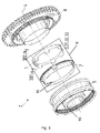
- FIG. 3 shows a schematic representation of a synchronization unit 2 with a friction ring. 1
- the synchronization unit 2 comprises in addition to the friction ring 1 in a conventional manner further a sliding sleeve 6 with a synchronizer body 15, a synchronizer ring 7, and a gear 8, wherein the aforementioned components are arranged coaxially with the friction ring axis 4, that in the operating state of the synchronizer ring 7 by the sliding sleeve. 6 is slidable along with the friction ring 1 along the friction ring axis 4 in the direction of the gear wheel 8, so that the inner friction surface 301 of the friction ring 3 with the gear wheel 8 can be brought into engagement.
- the synchronizer ring 7 and the friction ring 1 thereby form a structural unit 9 of the synchronization unit.
- the synchronizer ring 7 is in Fig. 3 made of brass, but it can also be made of stamped steel of conventional design.
- the cone of the synchronizer ring 7, which is formed by a contact surface 10, has the same large inner angle ⁇ 2 , that is identical to the installation angle ⁇ 2 of the friction ring 1.
- the contact surface 10 of the synchronizer ring 7 thus corresponds to the outer mounting surface 302 of the friction ring. 1
- the synchronizer ring 7 also has per se known, not shown coupling pockets for the segmented friction ring 1.
- the segmented friction ring 1 according to Fig. 3 is segmented into three equal friction ring segments 31, 32, 33, which for reasons of clarity in FIG Fig. 3 not in detail is shown.
- the friction ring is made in particular of sheet metal.
- the friction ring 1 has the mounting surface 302 with the installation angle ⁇ 2 , wherein the mounting surface 302 is used as a separation surface.
- the inner cone of the friction ring 1 is formed by the friction surface 301 with friction angle ⁇ 1 , where ⁇ 1 ⁇ 2 applies. This inner conical surface, so the friction surface 301 is used for synchronization.
- the friction ring can also act as a slotted ring according to the Fig. 4a and 4b be executed.
- the synchronizer ring 7 is axially displaced in the direction of the gear wheel 8, which is designed as a gear, and thus the three friction ring segments 31, 32, 33 of the friction ring 1 are detected by the angle ⁇ 2 .
- the synchronizer ring 7 and the segmented friction ring 1 are then moved together simultaneously and with the inner cone, so the friction surface 301 with friction angle ⁇ 1 , on the gear 8, which also has a corresponding counter cone with cone angle ⁇ 1 , intervene.
- the synchronizer ring 7 can then drive and index like a conventional synchronizer ring 7.
- the teeth of the sliding sleeve 6 are in contact with the teeth of the synchronizer ring 7 and thus generate, by the differential speed, a moment between the segmented friction ring 1 and the gear wheel eighth
- option 1 the friction surface on the inner cone of the segments with the small angle ⁇ 1 .
- the large release angle ⁇ 2 is on the outer cone surface of the segments.
- the friction surface on the outer cone of the segments has the small angle ⁇ 1 .
- the large release angle ⁇ 2 is on the inner cone surface of the segments, in practice option 1 is the preferred concept.
- FIG. 4a schematically an alternative embodiment of a friction ring 1 according to the invention in an expanded configuration with a radius R 1 is shown, for example, in the synchronization unit according to Fig. 3 is usable.
- the friction ring 1 comprises a slotted friction ring body 3.
- the friction ring body 3 In the friction ring body 3 exactly one slot 11 is arranged, which has a width B, which sweeps over in the circumferential direction U about 3 mm of the circumference of the friction ring body.
- FIG. 4b is the friction ring 1 according FIG. 4 shown in a contracted configuration with the radius R 2 .
- the slot 11 according to FIG. 5 has a smaller width B than the slot according to FIG. 4a .
- the friction ring can also be designed in particular so that touch in the contracted configuration, ie in the unloaded state, the opposite ends, so no slot is available. It is particularly advantageous if a contact pressure of 4 to 5 N is present at the ends.
- An expansion of the friction ring after a separation of the friction ring can be counteracted, for example, by introducing an internal stress on its surface, in particular on the installation surface. This can be done for example by nitriding or sandblasting.
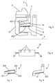
- FIG. 5 is a section of a synchronization unit 2 in an operating state, that is shown schematically in a synchronization process.
- the synchronizing unit 2 comprises a gear wheel 8, a synchronizer ring 7, a friction ring 1, a synchronizer hub 15 and a sliding sleeve 6.
- the synchronizer ring 7 is displaced in the direction of the gear wheel 8 to be synchronized so that the contact surface 10 of the synchronizer ring 7 on the mounting surface 302 of Friction ring 1 is applied, causing a frictional contact between a friction lining 303 of the friction surface 301 and the gear wheel 8 is formed and a speed equalization between gear wheel 8 and friction ring 1 and thus synchronizer ring 7 takes place.
- the contact surface 10 of the synchronizer ring 7 and / or the mounting surface 302 of the friction ring 1 in this case have an adhesion-reducing surface structure, in connection with the FIGS. 7, 8 and 9a - 9h will be received.
- FIG. 6 is very schematically illustrated a gear change transmission 20 for a vehicle, in particular a motor vehicle.
- the change-speed gearbox 20 has a transmission input shaft 21 and a transmission output shaft 22 and a total of three synchronization units 2, by means of which gear changes in the change-speed gearbox 20 can be performed.
- FIG. 7 is a friction ring 1 in a sectional view accordingly FIG. 5 shown.
- the friction ring 1 has a friction lining 303 on the inner friction surface 301 and a carbon layer in the form of a DLC layer 304 on the outer mounting surface 302 as an adhesion-reducing coating and thus as an adhesion-reducing surface structure.
- FIG. 8 is a synchronizer ring 7 in a sectional view accordingly FIG. 5 shown.
- the synchronizer ring 7 has at the contact surface 10 a carbon layer in the form of a DLC layer 305 as an adhesion-reducing coating and thus as an adhesion-reducing surface structure.
- Figures 9a - 9h show sections of contact surfaces 10 of synchronizer rings 7 and outer mounting surfaces 302 of friction rings 1 with different surface structures, which have all depressions.
- the recesses are designed as axial grooves 51, which extend substantially along the friction ring axis 4.
- the recesses are designed as radial grooves 52 which extend substantially in the circumferential direction U.
- the recesses are designed as holes 57, which can be designed as blind holes or through holes.
- the recesses are designed as V-grooves 53.
- the depressions are designed as a combination of axial grooves 51 and V-grooves 53 arranged therebetween.
- the recesses are designed as X-grooves 54.
- the depressions are designed as a laser texture 55.
- FIG. 9h the depressions 56 have been produced by means of a ball, sandblast or etching process.
Landscapes
- Engineering & Computer Science (AREA)
- General Engineering & Computer Science (AREA)
- Mechanical Engineering (AREA)
- Mechanical Operated Clutches (AREA)
Priority Applications (1)
| Application Number | Priority Date | Filing Date | Title |
|---|---|---|---|
| EP16175938.6A EP3112716B1 (fr) | 2015-06-26 | 2016-06-14 | Composant d'unitè de synchronisation d'une boîte manuelle à engrenage |
Applications Claiming Priority (1)
| Application Number | Priority Date | Filing Date | Title |
|---|---|---|---|
| EP15174118 | 2015-06-26 |
Related Child Applications (2)
| Application Number | Title | Priority Date | Filing Date |
|---|---|---|---|
| EP16175938.6A Division-Into EP3112716B1 (fr) | 2015-06-26 | 2016-06-14 | Composant d'unitè de synchronisation d'une boîte manuelle à engrenage |
| EP16175938.6A Division EP3112716B1 (fr) | 2015-06-26 | 2016-06-14 | Composant d'unitè de synchronisation d'une boîte manuelle à engrenage |
Publications (3)
| Publication Number | Publication Date |
|---|---|
| EP3109498A2 true EP3109498A2 (fr) | 2016-12-28 |
| EP3109498A3 EP3109498A3 (fr) | 2017-01-11 |
| EP3109498B1 EP3109498B1 (fr) | 2019-09-04 |
Family
ID=53510658
Family Applications (2)
| Application Number | Title | Priority Date | Filing Date |
|---|---|---|---|
| EP16175938.6A Active EP3112716B1 (fr) | 2015-06-26 | 2016-06-14 | Composant d'unitè de synchronisation d'une boîte manuelle à engrenage |
| EP16174414.9A Active EP3109498B1 (fr) | 2015-06-26 | 2016-06-14 | Composant pour une unité de synchronisation d'une boite manuelle à engrenage |
Family Applications Before (1)
| Application Number | Title | Priority Date | Filing Date |
|---|---|---|---|
| EP16175938.6A Active EP3112716B1 (fr) | 2015-06-26 | 2016-06-14 | Composant d'unitè de synchronisation d'une boîte manuelle à engrenage |
Country Status (6)
| Country | Link |
|---|---|
| US (2) | US20160377125A1 (fr) |
| EP (2) | EP3112716B1 (fr) |
| JP (1) | JP2017015252A (fr) |
| KR (1) | KR20170001591A (fr) |
| CN (1) | CN106286628B (fr) |
| BR (1) | BR102016014446A8 (fr) |
Cited By (2)
| Publication number | Priority date | Publication date | Assignee | Title |
|---|---|---|---|---|
| EP3184839A1 (fr) * | 2015-12-22 | 2017-06-28 | Oerlikon Friction Systems (Germany) GmbH | Unité de synchronisation pour une boite manuelle a engrenage |
| US10253824B2 (en) | 2015-10-07 | 2019-04-09 | OERLIKON FRICTION SYSTEMS (GERMANY) GmbH | Friction ring for a synchronization unit |
Families Citing this family (6)
| Publication number | Priority date | Publication date | Assignee | Title |
|---|---|---|---|---|
| DE102015100869B4 (de) * | 2015-01-21 | 2016-10-13 | Hoerbiger Antriebstechnik Holding Gmbh | Verfahren zur Herstellung eines Synchronrings sowie Synchronring für synchronisierte Schaltgetriebe |
| DE102016013716B4 (de) * | 2016-11-17 | 2018-09-13 | Diehl Metall Stiftung & Co. Kg | Synchronring |
| DE102017211425B4 (de) * | 2017-07-05 | 2021-06-24 | Audi Ag | Synchronisierelement für ein Getriebe, insbesondere eines Kraftfahrzeugs, Synchronisiereinrichtung mit zumindest einem solchen Synchronisierelement sowie Getriebe für ein Kraftfahrzeug |
| EP3473879B1 (fr) * | 2017-10-17 | 2020-09-30 | Ningbo Geely Automobile Research & Development Co. Ltd. | Bague de synchronisation |
| CN108458104B (zh) * | 2018-04-03 | 2019-09-06 | 吉林大学 | 一种基于单边压力控制系统的同步器摘挡过程控制方法 |
| CN114197373A (zh) * | 2021-12-14 | 2022-03-18 | 中国重汽集团柳州运力科迪亚克机械有限责任公司 | 抛雪筒摩擦环装置 |
Citations (1)
| Publication number | Priority date | Publication date | Assignee | Title |
|---|---|---|---|---|
| EP2677187A1 (fr) | 2012-06-18 | 2013-12-25 | Sulzer Friction Systems (Germany) GmbH | Anneau de friction, appareil de synchronisation, ainsi que boîte manuelle à engrenages pour un véhicule |
Family Cites Families (27)
| Publication number | Priority date | Publication date | Assignee | Title |
|---|---|---|---|---|
| DE3417813C1 (de) * | 1984-05-14 | 1985-06-05 | Sinterstahl GmbH, 8958 Füssen | Verwendung von Streusinter-Reibbelaegen in Reibkupplungen oder -bremsen |
| JPH0581538U (ja) * | 1992-10-08 | 1993-11-05 | 愛三工業株式会社 | シンクロナイザリング |
| JPH09144773A (ja) * | 1995-11-20 | 1997-06-03 | Kinousei Mokushitsu Shinsozai Gijutsu Kenkyu Kumiai | ウッドセラミックスからなる摩擦材の層を具えたシンクロナイザーリング |
| JP3645641B2 (ja) * | 1996-02-16 | 2005-05-11 | 株式会社ダイナックス | シンクロナイザーリング用摩擦材 |
| DE19858987A1 (de) * | 1998-12-21 | 2000-06-29 | Schaeffler Waelzlager Ohg | Spanlos gefertigter Synchronring mit strukturierten Reibflächen |
| JP2000234630A (ja) * | 1999-02-16 | 2000-08-29 | Aisin Ai Co Ltd | 変速機のシンクロナイザリング |
| WO2004111479A1 (fr) * | 2003-06-10 | 2004-12-23 | Oiles Corporation | Anneau de synchronisation |
| EP1666573B1 (fr) * | 2003-08-06 | 2019-05-15 | Nissan Motor Company Limited | Mecanisme coulissant a faible frottement et procede de reduction de frottement |
| US7069636B2 (en) * | 2003-10-02 | 2006-07-04 | Euroflamm Select Inc. | Friction facing method for use in a friction environment |
| US20060236523A1 (en) * | 2003-10-02 | 2006-10-26 | Sulzer Euroflamm Us Inc | Friction facing method for use in a friction environment |
| DE102005054085A1 (de) * | 2005-11-12 | 2007-05-16 | Schaeffler Kg | Synchronisationseinheit, insbesondere für Getriebe |
| CN100504097C (zh) * | 2006-03-28 | 2009-06-24 | 浙江吉利变速器有限公司 | 通槽式离合器 |
| JP4240092B2 (ja) * | 2006-09-07 | 2009-03-18 | トヨタ自動車株式会社 | 摩擦係合装置の支持構造および変速機 |
| DE102006061415A1 (de) * | 2006-12-23 | 2008-06-26 | Schaeffler Kg | Synchronring einer Synchronisiereinrichtung |
| EP2028386A1 (fr) * | 2007-08-23 | 2009-02-25 | Sulzer Euroflamm Germany GmbH | Anneau synchrone pour un dispositif de synchronisation, ébauche de garniture de friction et procédé destiné à la fabrication d'un anneau synchrone |
| DE102009012961B3 (de) * | 2009-03-12 | 2010-01-21 | Ab Skf | Verfahren zur Herstellung eines Ringes einer Synchronisationseinrichtung und Ring einer Synchronisationseinrichtung |
| JP4883128B2 (ja) * | 2009-04-09 | 2012-02-22 | トヨタ自動車株式会社 | 車両用フロントデファレンシャル装置 |
| WO2010140412A1 (fr) * | 2009-06-04 | 2010-12-09 | 田中精密工業株式会社 | Matériau de frottement par glissement |
| JP2011001598A (ja) * | 2009-06-18 | 2011-01-06 | Jtekt Corp | 摺動部材 |
| JP5692571B2 (ja) * | 2010-10-12 | 2015-04-01 | 株式会社ジェイテクト | Dlc被覆部材 |
| AT510943A1 (de) * | 2011-01-13 | 2012-07-15 | Miba Frictec Gmbh | Reibmaterial |
| US8550226B2 (en) * | 2011-01-25 | 2013-10-08 | GM Global Technology Operations LLC | Transmission synchronizer assembly |
| JP6115140B2 (ja) * | 2013-01-15 | 2017-04-19 | 株式会社ジェイテクト | 摺動部材の製造方法およびクラッチプレートの製造方法 |
| DE102013106112A1 (de) * | 2013-06-12 | 2014-12-31 | Hoerbiger Antriebstechnik Holding Gmbh | Synchronring für eine Synchronisationseinheit eines Schaltgetriebes sowie Synchronisationseinheit mit einem solchen Synchronring |
| RU2614403C1 (ru) * | 2013-09-18 | 2017-03-28 | Ниссан Мотор Ко., Лтд. | Фрикционный элемент зацепления, сухая муфта и способ изготовления фрикционного элемента зацепления |
| ES2663475T3 (es) * | 2013-12-17 | 2018-04-12 | OERLIKON FRICTION SYSTEMS (GERMANY) GmbH | Anillo de fricción, anillo de sincronización, unidad de sincronización, así como una caja de cambios de velocidades para un vehículo |
| DE102015009706A1 (de) * | 2015-07-30 | 2017-02-02 | Diehl Metall Stiftung & Co. Kg | Verfahren zur Herstellung eines Synchronrings |
-
2016
- 2016-06-10 JP JP2016116525A patent/JP2017015252A/ja active Pending
- 2016-06-13 KR KR1020160073103A patent/KR20170001591A/ko not_active Ceased
- 2016-06-14 EP EP16175938.6A patent/EP3112716B1/fr active Active
- 2016-06-14 EP EP16174414.9A patent/EP3109498B1/fr active Active
- 2016-06-16 US US15/184,509 patent/US20160377125A1/en not_active Abandoned
- 2016-06-20 BR BR102016014446A patent/BR102016014446A8/pt active Search and Examination
- 2016-06-24 CN CN201610466870.7A patent/CN106286628B/zh active Active
-
2019
- 2019-05-01 US US16/400,746 patent/US20190323565A1/en not_active Abandoned
Patent Citations (1)
| Publication number | Priority date | Publication date | Assignee | Title |
|---|---|---|---|---|
| EP2677187A1 (fr) | 2012-06-18 | 2013-12-25 | Sulzer Friction Systems (Germany) GmbH | Anneau de friction, appareil de synchronisation, ainsi que boîte manuelle à engrenages pour un véhicule |
Cited By (3)
| Publication number | Priority date | Publication date | Assignee | Title |
|---|---|---|---|---|
| US10253824B2 (en) | 2015-10-07 | 2019-04-09 | OERLIKON FRICTION SYSTEMS (GERMANY) GmbH | Friction ring for a synchronization unit |
| EP3153732B1 (fr) * | 2015-10-07 | 2023-06-07 | Oerlikon Friction Systems (Germany) GmbH | Anneau de friction pour une unité de synchronisation |
| EP3184839A1 (fr) * | 2015-12-22 | 2017-06-28 | Oerlikon Friction Systems (Germany) GmbH | Unité de synchronisation pour une boite manuelle a engrenage |
Also Published As
| Publication number | Publication date |
|---|---|
| KR20170001591A (ko) | 2017-01-04 |
| BR102016014446A8 (pt) | 2018-02-27 |
| EP3109498B1 (fr) | 2019-09-04 |
| EP3112716A2 (fr) | 2017-01-04 |
| CN106286628A (zh) | 2017-01-04 |
| US20160377125A1 (en) | 2016-12-29 |
| EP3112716A3 (fr) | 2017-01-11 |
| CN106286628B (zh) | 2021-08-10 |
| US20190323565A1 (en) | 2019-10-24 |
| EP3112716B1 (fr) | 2022-01-19 |
| JP2017015252A (ja) | 2017-01-19 |
| EP3109498A3 (fr) | 2017-01-11 |
Similar Documents
| Publication | Publication Date | Title |
|---|---|---|
| EP3109498B1 (fr) | Composant pour une unité de synchronisation d'une boite manuelle à engrenage | |
| EP2894363B1 (fr) | Anneau de friction, anneau de synchronisation, appareil de synchronisation, ainsi que boîte manuelle à engrenages pour un véhicule | |
| EP2677187B1 (fr) | Anneau de friction, appareil de synchronisation, ainsi que boîte manuelle à engrenages pour un véhicule | |
| EP2104790B1 (fr) | Bague de synchronisation d'un dispositif de synchronisation | |
| EP2955417B1 (fr) | Système de transmission de véhicule hybride | |
| DE102019128160B3 (de) | Zweiganggetriebe für Elektromotoren | |
| WO2008155173A1 (fr) | Dispositif de synchronisation | |
| DE102014107926A1 (de) | Synchronring für eine Synchronisationseinheit eines Schaltgetriebes sowie Verfahren zum Herstellen eines solchen Synchronrings | |
| DE202016100792U1 (de) | Synchronisiervorrichtung und Schaltgetriebe mit einer solchen Synchronisiervorrichtung | |
| EP1664566B1 (fr) | Embrayage de synchronisation pour un engrenage reducteur de vehicule automobile | |
| DE102008061967A1 (de) | Synchronisiereinrichtung | |
| EP3354922B1 (fr) | Dispositif de synchronisation et procédé de synchronisation | |
| DE102013215617B3 (de) | Kupplungskörper einer Synchronisiervorrichtung | |
| EP4080076B1 (fr) | Dispositif de roue libre commutable pour un dispositif de transmission | |
| WO2007128359A1 (fr) | Procédé de fabrication d'un élément de transmission | |
| EP2238366B1 (fr) | Bague de friction | |
| DE102005007647A1 (de) | Synchronisierungseinrichtung für ein Schaltgetriebe eines Kraftfahrzeuges | |
| EP3153732B1 (fr) | Anneau de friction pour une unité de synchronisation | |
| DE102015113614B4 (de) | Synchronring eines Schaltgetriebes sowie Schaltgetriebe mit einem solchen Synchronring | |
| DE102019134433A1 (de) | Kupplungskörperanordnung für eine Synchronisiereinrichtung eines Getriebes | |
| DE102017211425B4 (de) | Synchronisierelement für ein Getriebe, insbesondere eines Kraftfahrzeugs, Synchronisiereinrichtung mit zumindest einem solchen Synchronisierelement sowie Getriebe für ein Kraftfahrzeug | |
| DE102013000115A1 (de) | Welle-Nabe-Verbindung und Schaltgetriebe für ein Kraftfahrzeug | |
| EP3252334B1 (fr) | Unité de synchronisation d'une boite manuelle à engrenage | |
| DE102008061969A1 (de) | Kupplung | |
| DE102008045593A1 (de) | Reibkörper für eine Synchronisiereinrichtung eines Getriebes sowie Verfahren zur Herstellung eines solchen Reibkörpers |
Legal Events
| Date | Code | Title | Description |
|---|---|---|---|
| PUAI | Public reference made under article 153(3) epc to a published international application that has entered the european phase |
Free format text: ORIGINAL CODE: 0009012 |
|
| STAA | Information on the status of an ep patent application or granted ep patent |
Free format text: STATUS: THE APPLICATION HAS BEEN PUBLISHED |
|
| PUAL | Search report despatched |
Free format text: ORIGINAL CODE: 0009013 |
|
| AK | Designated contracting states |
Kind code of ref document: A2 Designated state(s): AL AT BE BG CH CY CZ DE DK EE ES FI FR GB GR HR HU IE IS IT LI LT LU LV MC MK MT NL NO PL PT RO RS SE SI SK SM TR |
|
| AX | Request for extension of the european patent |
Extension state: BA ME |
|
| AK | Designated contracting states |
Kind code of ref document: A3 Designated state(s): AL AT BE BG CH CY CZ DE DK EE ES FI FR GB GR HR HU IE IS IT LI LT LU LV MC MK MT NL NO PL PT RO RS SE SI SK SM TR |
|
| AX | Request for extension of the european patent |
Extension state: BA ME |
|
| RIC1 | Information provided on ipc code assigned before grant |
Ipc: F16D 23/02 20060101AFI20161207BHEP |
|
| STAA | Information on the status of an ep patent application or granted ep patent |
Free format text: STATUS: REQUEST FOR EXAMINATION WAS MADE |
|
| 17P | Request for examination filed |
Effective date: 20170711 |
|
| RBV | Designated contracting states (corrected) |
Designated state(s): AL AT BE BG CH CY CZ DE DK EE ES FI FR GB GR HR HU IE IS IT LI LT LU LV MC MK MT NL NO PL PT RO RS SE SI SK SM TR |
|
| GRAP | Despatch of communication of intention to grant a patent |
Free format text: ORIGINAL CODE: EPIDOSNIGR1 |
|
| STAA | Information on the status of an ep patent application or granted ep patent |
Free format text: STATUS: GRANT OF PATENT IS INTENDED |
|
| INTG | Intention to grant announced |
Effective date: 20190523 |
|
| GRAS | Grant fee paid |
Free format text: ORIGINAL CODE: EPIDOSNIGR3 |
|
| GRAA | (expected) grant |
Free format text: ORIGINAL CODE: 0009210 |
|
| STAA | Information on the status of an ep patent application or granted ep patent |
Free format text: STATUS: THE PATENT HAS BEEN GRANTED |
|
| AK | Designated contracting states |
Kind code of ref document: B1 Designated state(s): AL AT BE BG CH CY CZ DE DK EE ES FI FR GB GR HR HU IE IS IT LI LT LU LV MC MK MT NL NO PL PT RO RS SE SI SK SM TR |
|
| REG | Reference to a national code |
Ref country code: GB Ref legal event code: FG4D Free format text: NOT ENGLISH |
|
| REG | Reference to a national code |
Ref country code: CH Ref legal event code: EP |
|
| REG | Reference to a national code |
Ref country code: AT Ref legal event code: REF Ref document number: 1175767 Country of ref document: AT Kind code of ref document: T Effective date: 20190915 |
|
| REG | Reference to a national code |
Ref country code: DE Ref legal event code: R096 Ref document number: 502016006375 Country of ref document: DE |
|
| REG | Reference to a national code |
Ref country code: IE Ref legal event code: FG4D Free format text: LANGUAGE OF EP DOCUMENT: GERMAN |
|
| REG | Reference to a national code |
Ref country code: NL Ref legal event code: MP Effective date: 20190904 |
|
| REG | Reference to a national code |
Ref country code: LT Ref legal event code: MG4D |
|
| PG25 | Lapsed in a contracting state [announced via postgrant information from national office to epo] |
Ref country code: NO Free format text: LAPSE BECAUSE OF FAILURE TO SUBMIT A TRANSLATION OF THE DESCRIPTION OR TO PAY THE FEE WITHIN THE PRESCRIBED TIME-LIMIT Effective date: 20191204 Ref country code: SE Free format text: LAPSE BECAUSE OF FAILURE TO SUBMIT A TRANSLATION OF THE DESCRIPTION OR TO PAY THE FEE WITHIN THE PRESCRIBED TIME-LIMIT Effective date: 20190904 Ref country code: FI Free format text: LAPSE BECAUSE OF FAILURE TO SUBMIT A TRANSLATION OF THE DESCRIPTION OR TO PAY THE FEE WITHIN THE PRESCRIBED TIME-LIMIT Effective date: 20190904 Ref country code: LT Free format text: LAPSE BECAUSE OF FAILURE TO SUBMIT A TRANSLATION OF THE DESCRIPTION OR TO PAY THE FEE WITHIN THE PRESCRIBED TIME-LIMIT Effective date: 20190904 Ref country code: HR Free format text: LAPSE BECAUSE OF FAILURE TO SUBMIT A TRANSLATION OF THE DESCRIPTION OR TO PAY THE FEE WITHIN THE PRESCRIBED TIME-LIMIT Effective date: 20190904 Ref country code: BG Free format text: LAPSE BECAUSE OF FAILURE TO SUBMIT A TRANSLATION OF THE DESCRIPTION OR TO PAY THE FEE WITHIN THE PRESCRIBED TIME-LIMIT Effective date: 20191204 |
|
| PG25 | Lapsed in a contracting state [announced via postgrant information from national office to epo] |
Ref country code: ES Free format text: LAPSE BECAUSE OF FAILURE TO SUBMIT A TRANSLATION OF THE DESCRIPTION OR TO PAY THE FEE WITHIN THE PRESCRIBED TIME-LIMIT Effective date: 20190904 Ref country code: AL Free format text: LAPSE BECAUSE OF FAILURE TO SUBMIT A TRANSLATION OF THE DESCRIPTION OR TO PAY THE FEE WITHIN THE PRESCRIBED TIME-LIMIT Effective date: 20190904 Ref country code: LV Free format text: LAPSE BECAUSE OF FAILURE TO SUBMIT A TRANSLATION OF THE DESCRIPTION OR TO PAY THE FEE WITHIN THE PRESCRIBED TIME-LIMIT Effective date: 20190904 Ref country code: RS Free format text: LAPSE BECAUSE OF FAILURE TO SUBMIT A TRANSLATION OF THE DESCRIPTION OR TO PAY THE FEE WITHIN THE PRESCRIBED TIME-LIMIT Effective date: 20190904 Ref country code: GR Free format text: LAPSE BECAUSE OF FAILURE TO SUBMIT A TRANSLATION OF THE DESCRIPTION OR TO PAY THE FEE WITHIN THE PRESCRIBED TIME-LIMIT Effective date: 20191205 |
|
| PG25 | Lapsed in a contracting state [announced via postgrant information from national office to epo] |
Ref country code: RO Free format text: LAPSE BECAUSE OF FAILURE TO SUBMIT A TRANSLATION OF THE DESCRIPTION OR TO PAY THE FEE WITHIN THE PRESCRIBED TIME-LIMIT Effective date: 20190904 Ref country code: PT Free format text: LAPSE BECAUSE OF FAILURE TO SUBMIT A TRANSLATION OF THE DESCRIPTION OR TO PAY THE FEE WITHIN THE PRESCRIBED TIME-LIMIT Effective date: 20200106 Ref country code: EE Free format text: LAPSE BECAUSE OF FAILURE TO SUBMIT A TRANSLATION OF THE DESCRIPTION OR TO PAY THE FEE WITHIN THE PRESCRIBED TIME-LIMIT Effective date: 20190904 Ref country code: PL Free format text: LAPSE BECAUSE OF FAILURE TO SUBMIT A TRANSLATION OF THE DESCRIPTION OR TO PAY THE FEE WITHIN THE PRESCRIBED TIME-LIMIT Effective date: 20190904 Ref country code: NL Free format text: LAPSE BECAUSE OF FAILURE TO SUBMIT A TRANSLATION OF THE DESCRIPTION OR TO PAY THE FEE WITHIN THE PRESCRIBED TIME-LIMIT Effective date: 20190904 |
|
| PG25 | Lapsed in a contracting state [announced via postgrant information from national office to epo] |
Ref country code: CZ Free format text: LAPSE BECAUSE OF FAILURE TO SUBMIT A TRANSLATION OF THE DESCRIPTION OR TO PAY THE FEE WITHIN THE PRESCRIBED TIME-LIMIT Effective date: 20190904 Ref country code: IS Free format text: LAPSE BECAUSE OF FAILURE TO SUBMIT A TRANSLATION OF THE DESCRIPTION OR TO PAY THE FEE WITHIN THE PRESCRIBED TIME-LIMIT Effective date: 20200224 Ref country code: SM Free format text: LAPSE BECAUSE OF FAILURE TO SUBMIT A TRANSLATION OF THE DESCRIPTION OR TO PAY THE FEE WITHIN THE PRESCRIBED TIME-LIMIT Effective date: 20190904 Ref country code: SK Free format text: LAPSE BECAUSE OF FAILURE TO SUBMIT A TRANSLATION OF THE DESCRIPTION OR TO PAY THE FEE WITHIN THE PRESCRIBED TIME-LIMIT Effective date: 20190904 |
|
| REG | Reference to a national code |
Ref country code: DE Ref legal event code: R097 Ref document number: 502016006375 Country of ref document: DE |
|
| PLBE | No opposition filed within time limit |
Free format text: ORIGINAL CODE: 0009261 |
|
| STAA | Information on the status of an ep patent application or granted ep patent |
Free format text: STATUS: NO OPPOSITION FILED WITHIN TIME LIMIT |
|
| PG2D | Information on lapse in contracting state deleted |
Ref country code: IS |
|
| PG25 | Lapsed in a contracting state [announced via postgrant information from national office to epo] |
Ref country code: DK Free format text: LAPSE BECAUSE OF FAILURE TO SUBMIT A TRANSLATION OF THE DESCRIPTION OR TO PAY THE FEE WITHIN THE PRESCRIBED TIME-LIMIT Effective date: 20190904 Ref country code: IS Free format text: LAPSE BECAUSE OF FAILURE TO SUBMIT A TRANSLATION OF THE DESCRIPTION OR TO PAY THE FEE WITHIN THE PRESCRIBED TIME-LIMIT Effective date: 20200105 |
|
| 26N | No opposition filed |
Effective date: 20200605 |
|
| PG25 | Lapsed in a contracting state [announced via postgrant information from national office to epo] |
Ref country code: SI Free format text: LAPSE BECAUSE OF FAILURE TO SUBMIT A TRANSLATION OF THE DESCRIPTION OR TO PAY THE FEE WITHIN THE PRESCRIBED TIME-LIMIT Effective date: 20190904 |
|
| PG25 | Lapsed in a contracting state [announced via postgrant information from national office to epo] |
Ref country code: MC Free format text: LAPSE BECAUSE OF FAILURE TO SUBMIT A TRANSLATION OF THE DESCRIPTION OR TO PAY THE FEE WITHIN THE PRESCRIBED TIME-LIMIT Effective date: 20190904 |
|
| REG | Reference to a national code |
Ref country code: CH Ref legal event code: PL |
|
| PG25 | Lapsed in a contracting state [announced via postgrant information from national office to epo] |
Ref country code: LU Free format text: LAPSE BECAUSE OF NON-PAYMENT OF DUE FEES Effective date: 20200614 |
|
| REG | Reference to a national code |
Ref country code: BE Ref legal event code: MM Effective date: 20200630 |
|
| PG25 | Lapsed in a contracting state [announced via postgrant information from national office to epo] |
Ref country code: IE Free format text: LAPSE BECAUSE OF NON-PAYMENT OF DUE FEES Effective date: 20200614 Ref country code: CH Free format text: LAPSE BECAUSE OF NON-PAYMENT OF DUE FEES Effective date: 20200630 Ref country code: LI Free format text: LAPSE BECAUSE OF NON-PAYMENT OF DUE FEES Effective date: 20200630 |
|
| PG25 | Lapsed in a contracting state [announced via postgrant information from national office to epo] |
Ref country code: BE Free format text: LAPSE BECAUSE OF NON-PAYMENT OF DUE FEES Effective date: 20200630 |
|
| PG25 | Lapsed in a contracting state [announced via postgrant information from national office to epo] |
Ref country code: TR Free format text: LAPSE BECAUSE OF FAILURE TO SUBMIT A TRANSLATION OF THE DESCRIPTION OR TO PAY THE FEE WITHIN THE PRESCRIBED TIME-LIMIT Effective date: 20190904 Ref country code: MT Free format text: LAPSE BECAUSE OF FAILURE TO SUBMIT A TRANSLATION OF THE DESCRIPTION OR TO PAY THE FEE WITHIN THE PRESCRIBED TIME-LIMIT Effective date: 20190904 Ref country code: CY Free format text: LAPSE BECAUSE OF FAILURE TO SUBMIT A TRANSLATION OF THE DESCRIPTION OR TO PAY THE FEE WITHIN THE PRESCRIBED TIME-LIMIT Effective date: 20190904 |
|
| PG25 | Lapsed in a contracting state [announced via postgrant information from national office to epo] |
Ref country code: MK Free format text: LAPSE BECAUSE OF FAILURE TO SUBMIT A TRANSLATION OF THE DESCRIPTION OR TO PAY THE FEE WITHIN THE PRESCRIBED TIME-LIMIT Effective date: 20190904 |
|
| REG | Reference to a national code |
Ref country code: AT Ref legal event code: MM01 Ref document number: 1175767 Country of ref document: AT Kind code of ref document: T Effective date: 20210614 |
|
| PG25 | Lapsed in a contracting state [announced via postgrant information from national office to epo] |
Ref country code: AT Free format text: LAPSE BECAUSE OF NON-PAYMENT OF DUE FEES Effective date: 20210614 |
|
| PGFP | Annual fee paid to national office [announced via postgrant information from national office to epo] |
Ref country code: DE Payment date: 20250626 Year of fee payment: 10 |
|
| PGFP | Annual fee paid to national office [announced via postgrant information from national office to epo] |
Ref country code: GB Payment date: 20250617 Year of fee payment: 10 |
|
| PGFP | Annual fee paid to national office [announced via postgrant information from national office to epo] |
Ref country code: FR Payment date: 20250624 Year of fee payment: 10 |
|
| PGFP | Annual fee paid to national office [announced via postgrant information from national office to epo] |
Ref country code: IT Payment date: 20250623 Year of fee payment: 10 |