EP3109558A1 - Konvektionsheizungsvorrichtung für öfen - Google Patents
Konvektionsheizungsvorrichtung für öfen Download PDFInfo
- Publication number
- EP3109558A1 EP3109558A1 EP16175624.2A EP16175624A EP3109558A1 EP 3109558 A1 EP3109558 A1 EP 3109558A1 EP 16175624 A EP16175624 A EP 16175624A EP 3109558 A1 EP3109558 A1 EP 3109558A1
- Authority
- EP
- European Patent Office
- Prior art keywords
- fan cover
- cut
- heating device
- outlet section
- fan
- Prior art date
- Legal status (The legal status is an assumption and is not a legal conclusion. Google has not performed a legal analysis and makes no representation as to the accuracy of the status listed.)
- Granted
Links
Images


Classifications
-
- F—MECHANICAL ENGINEERING; LIGHTING; HEATING; WEAPONS; BLASTING
- F24—HEATING; RANGES; VENTILATING
- F24C—DOMESTIC STOVES OR RANGES ; DETAILS OF DOMESTIC STOVES OR RANGES, OF GENERAL APPLICATION
- F24C15/00—Details
- F24C15/32—Arrangements of ducts for hot gases, e.g. in or around baking ovens
- F24C15/322—Arrangements of ducts for hot gases, e.g. in or around baking ovens with forced circulation
- F24C15/325—Arrangements of ducts for hot gases, e.g. in or around baking ovens with forced circulation electrically-heated
-
- F—MECHANICAL ENGINEERING; LIGHTING; HEATING; WEAPONS; BLASTING
- F24—HEATING; RANGES; VENTILATING
- F24C—DOMESTIC STOVES OR RANGES ; DETAILS OF DOMESTIC STOVES OR RANGES, OF GENERAL APPLICATION
- F24C15/00—Details
- F24C15/36—Protective guards, e.g. for preventing access to heated parts
Definitions
- the present invention relates to a convection heating device for an oven cavity of a cooking oven. Further, the present invention relates to a fan cover for a convection heating device in an oven cavity of a cooking oven. Moreover, the present invention relates to a cooking oven with a convection heating device.
- a radial fan driven by a motor rotates and generates an air flow taken from the oven cavity through an inlet of a fan cover arranged in front of the rear wall of the oven cavity.
- Said fan cover is a separating wall between a convection heating device and the proper oven cavity.
- the convection heating device forms the rear portion of the oven cavity.
- the radial fan is arranged at the centre of the rear wall of the oven cavity. Then, the air flow is heated up by a heating element arranged between the fan cover and the rear wall of the oven cavity.
- the air flow enters the proper oven cavity again through opening in an outer portion of the fan cover or through a gap between the border of the fan cover and the rear wall of the oven cavity.
- the structure of the fan cover determines the geometric distribution of the air flow into the proper oven cavity.
- FIG 5 illustrates a schematic front view of the convection heating device in the oven cavity of the cooking oven according to the prior art.
- Said convection heating device is arranged in a rear portion of the oven cavity 10 and directly in front of the rear wall 12 of said oven cavity 10.
- the convection heating device comprises the fan cover 14, the radial fan 16 and the heating element 18.
- the fan cover 14 is substantially formed as a sheet and arranged parallel to the rear wall 12 of the oven cavity 10.
- the radial fan 16 is arranged between the fan cover 14 and the rear wall 12. Further, the radial fan 16 is arranged in the central portion of the rear wall 12.
- the rotation axis of the radial fan 16 extends perpendicular to the planes of the fan cover 14 and the rear wall 12.
- the heating element 18 encloses the radial fan 16.
- the fan cover 14 comprises the inlet section 20 and the outlet section 22.
- the inlet section 20 is arranged in the central portion of the fan cover 14 and in front of the radial fan 16.
- the outlet section 22 is formed between the border of the fan cover 16 and the rear wall 12 of the oven cavity 10.
- the radial fan 16 sucks the airflow 26 from the centre of the oven cavity 10 through the inlet section 20.
- the airflow 26 to the radial fan 16 streams parallel to the rotation axis of the radial fan 16. From the radial fan 16 the airflow 26 streams radially to the rotation axis of the radial fan 16 and then through the outlet section 22 into the oven cavity 10.
- FIG 6 illustrates a schematic top view of the convection heating device in the oven cavity 10 of the cooking oven according to the prior art.
- the radial fan 16 sucks the airflow 26 from the centre of the oven cavity 10 through the inlet section 20, wherein said airflow 26 streams parallel to the rotation axis of the radial fan 16. Afterwards the air flow 26 from the radial fan 16 radially to the rotation axis of the radial fan 16 and between the fan cover 14 and the rear wall 12 of the oven cavity 10 and then through the outlet section 22 into the oven cavity 10. Thereby a substantial part of the air flow 26 streams along the side walls of the oven cavity 10 and towards to an oven door and is then redirected to the central portion of the oven cavity 10.
- the fan cover 14 avoids that the air flow 26 is directly blown from the heating element to the food stuff in the centre of the oven cavity 10.
- the side walls of the oven cavity 10 are heated up strongly, since a substantial part of the air flow 26 streams along said side walls.
- the side walls form a large thermal mass, so that the energy losses to the ambient increase and therefore energy consumption increases. It would be advantageous, if the heating-up of the side walls of the oven cavity 10 could be reduced.
- the object is achieved by the convection heating device according to claim 1.
- a convection heating device for an oven cavity of a cooking oven wherein said convection heating device is arrangeable or arranged at a rear wall of the oven cavity, and wherein:
- the core of the present invention is the orientation of the cut-outs of the outlet section with respect to the directions of air flows from the radial fan on the one hand and the deflecting plate extending rearwards on the other hand.
- the air flows from the radial fan have radial components, but also tangential components.
- the orientation of the cut-out of the outlet section allows that a maximum part of the air flow reaches perpendicularly the longitudinal side of said cut-out.
- the deflecting plate extending rearwards is preferably placed upstream respect to the incoming flow, and generates favoured turbulences, preferably which guide the air flow into said cut out so air flow emerge perpendicular to the fan cover.
- the airflow from the convection heating device into the oven cavity removes away from the side walls of the oven cavity on the one hand and passes by the food stuff arranged in the centre of said oven cavity on the other hand.
- the heating-up of the side walls of the oven cavity is reduced and the heat distribution inside the oven cavity is substantially even.
- the inventive convection heating device avoids energy losses in the environment of the side walls of the oven cavity.
- angles between the longitudinal axes of the cut-outs of the outlet section and the corresponding reference axes are between 30° and 60°, in particular between 40° and 50°.
- the angles are adapted to the direction of the airflow from the radial fan.
- Said airflow from the radial fan has a radial and a tangential component.
- the deflecting plate has the same size as the corresponding cut-out.
- the deflecting plate extends perpendicular to the main plane of the fan cover.
- At least one longitudinal side of the cut-outs of the outlet section is linear.
- At least one deflecting plate may be plane.
- At least one longitudinal side of the cut-outs of the outlet section is curved.
- the at least one curved longitudinal side of the cut-out of the outlet section may be concave to the centre of the fan cover.
- At least one deflecting plate may be curved.
- the curved deflecting plate has the same curvature as the corresponding curved longitudinal side of the cut-out.
- the size of the inlet section of the fan cover may be adapted to the size of the radial fan. This optimizes the air flow from the oven cavity into the convection heating device.
- the present invention relates to a fan cover for a convection heating device in an oven cavity of a cooking oven, wherein:
- the fan cover is provided for the convection heating device mentioned above.
- the at least one heating element encloses the radial fan.
- the at least one heating element is a ring heating element.
- the present invention relates to a cooking oven with a convection heating device, wherein the cooking oven comprises a convection heating device and/or a fan cover mentioned above.
- the width and/or the height of the fan cover are marginally smaller than the width and the height, respectively, of the rear wall of the oven cavity.
- a space between the fan cover, the side wall of said fan cover and the rear wall of the oven cavity is closed, without regard to the inlet section and outlet section.
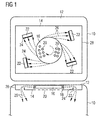
- FIG 1 illustrates a schematic front view and top view of a convection heating device in an oven cavity 10 of a cooking oven according to a first embodiment of the present invention.
- the front view of the convection heating device is shown in the upper picture in FIG 1 , while the top view of said convection heating device is shown in the lower picture therein.
- the convection heating device is arranged in a rear portion of the oven cavity 10 and directly in front of the rear wall 12 of said oven cavity 10.
- the convection heating device comprises a fan cover 14, a radial fan 16 and a heating element 18.
- the fan cover 14 is substantially formed as a sheet and arranged parallel to the rear wall 12 of the oven cavity 10.
- the radial fan 16 is arranged between the fan cover 14 and the rear wall 12.
- the radial fan 16 is arranged in a central portion of the rear wall 12.
- the rotation axis of the radial fan 16 extends perpendicular to the planes of the fan cover 14 and the rear wall 12.
- the heating element 18 encloses the radial fan 16.
- the fan cover 14 comprises an inlet section 20 and an outlet section 22.
- the inlet section 20 is arranged in a central portion of the fan cover 14.
- the inlet section 20 includes a plurality of holes. Said plurality of holes is substantially arranged in front of the radial fan 16.
- the outlet section 22 includes a number of cut-outs arranged in an outer portion of the fan cover 16.
- the outlet section 22 of the fan cover 14 includes four cut-outs.
- each cut-out has a rectangular shape and hence four edges. The longitudinal sides of the rectangular cut-outs are arranged substantially perpendicular to the direction of the airflow from the radial fan 16.
- a side wall 28 encloses the border of said fan cover 14.
- the side wall 28 extends perpendicular to the fan cover 14.
- the fan cover 14 and the side wall 28 are formed as a single-piece part.
- the side wall 28 extends rearwards from the border of the fan cover 14 to the rear wall 12 of the oven cavity 10.
- the rear wall 12, the fan cover 14 and the side wall 28 form a space. Without regard to the inlet section 20 and outlet section 22, said space is a closed space.
- each cut-out includes a deflecting plate 24 at one edge.
- the deflecting plate 24 is arranged at that edge, which is the closest to the radial fan 16 and to the centre of the fan cover 14.
- the deflecting plates 24 are bended rearward.
- the planes of the deflecting plates 24 extend substantially perpendicular to the planes of the rear wall 12 and fan cover 14.
- the area of each deflecting plate 24 is the same as the corresponding cut-out.
- the deflecting plate 24 may be obtained by a U-shaped cut in the fan cover 14, wherein the resulting flap is subsequently bended rearwards.
- the deflecting plates 24 generate favoured turbulences. Said turbulence contribute that the airflow from the convection heating device into the oven cavity, preferably emerging perpendicularly to the fan cover 14, and therefore removes away from the side walls of the oven cavity on the one hand and passes by the food stuff arranged in the centre of said oven cavity on the other hand.
- the radial fan 16 sucks the airflow 26 from the centre of the oven cavity 10 through the inlet section 20.
- the airflow 26 to the radial fan 16 streams parallel to the rotation axis of the radial fan 16.
- the airflow 26 from the radial fan 16 streams radial to the rotation axis of the radial fan 16.
- the airflow 26 from the radial fan 16 has also a component tangential to the rotation axis of the radial fan 16.
- the radial fan 16 blows the airflow 26 between the rear wall 12 and the fan cover 14 and parallel to planes of the rear wall 12 and fan cover 14.
- the airflow 26 from the radial fan 16 is deflected by the deflecting plates 24, streams through the cut-outs of the outlet section 22 and substantially forwards into a central portion of the oven cavity 10.
- the airflow 26 from the radial fan 16 has also a component tangential to the rotation axis of the radial fan 16.
- the orientation of the rectangular cut-outs are arranged substantially perpendicular to the direction of the airflow 26 from the radial fan 16.
- FIG 2 illustrates a schematic front view and top view of the convection heating device in the oven cavity 10 of the cooking oven according to a second embodiment of the present invention.
- the front view of the convection heating device is shown in the upper picture in FIG 2
- the top view of said convection heating device is shown in the lower picture therein.
- the convection heating device according to the second embodiment has substantially the same structure as the convection heating device of the first embodiment.
- the first and second embodiments differ in the shapes of the cut-outs of the outlet section 22.
- the longitudinal sides of the cut-outs are curved.
- the longitudinal sides of the cut-outs are concave in relation to the incident air flow 26.
- the directions of the incident air flow 26 are perpendicular to the corresponding sections of the longitudinal side.
- the deflecting plates 24 are similarly curved as the corresponding longitudinal sides.
- the convection heating devices according to the first and second embodiments may be combined.
- the fan cover 14 may include one or more cut-outs with linear longitudinal sides as well as one or more cut-outs with curved longitudinal sides.
- FIG 3 illustrates a schematic top view of the convection heating device in the oven cavity 10 of the cooking oven according to the first and second embodiment of the present invention.
- FIG 3 clarifies the distribution of the airflow 26.
- the airflow 26 is sucked by the radial fan 16 from the centre of the oven cavity 10 through the inlet section 20, wherein the airflow 26 to the radial fan 16 streams substantially parallel to the rotation axis of the radial fan 16. Then, the airflow 26 leaves the radial fan 16 radial to the rotation axis of said radial fan 16, wherein the airflow 26 is blown by the radial fan 16 between the rear wall 12 and the fan cover 14 and parallel to planes of said rear wall 12 and fan cover 14. Afterwards, the airflow 26 from the radial fan 16 is deflected by the deflecting plates 24, streams through the cut-outs of the outlet section 22 and substantially forwards into the oven cavity 10.
- the distance between the airflow 26 and the side wall of the oven cavity 10 increases.
- the hot airflow 26 does not directly impact onto the side walls of the oven cavity 10.
- the hot airflow 26 does not directly impact onto food stuff in the centre of the oven cavity 10.
- FIG 4 illustrates a detailed schematic top view of the convection heating device in the oven cavity 10 of the cooking oven according to the first and second embodiment of the present invention.
- FIG 4 shows the environment around a cut-out of the outlet section 22.
- Turbulences 30 are formed downstream the deflecting plate 24. Said turbulences 30 allow the deflection of the air flow 26. Without the deflecting plate 24, the air flow 26 would stream lineally through the cut-out into the oven cavity 10 and then towards to the side wall of said oven cavity.
- FIG 5 illustrates a schematic front view of the convection heating device in the oven cavity of the cooking oven according to the prior art.
- the convection heating device of the prior art is arranged in a rear portion of the oven cavity 10 and directly in front of the rear wall 12 of said oven cavity 10.
- the convection heating device comprises the fan cover 14, the radial fan 16 and the heating element 18.
- the fan cover 14 is substantially formed as a sheet and arranged parallel to the rear wall 12 of the oven cavity 10.
- the radial fan 16 is arranged between the fan cover 14 and the rear wall 12.
- the radial fan 16 is arranged in a central portion of the rear wall 12.
- the rotation axis of the radial fan 16 extends perpendicular to the planes of the fan cover 14 and the rear wall 12.
- the heating element 18 encloses the radial fan 16.
- the fan cover 14 comprises the inlet section 20 and the outlet section 22.
- the inlet section 20 is arranged in a central portion of the fan cover 14 and in front of the radial fan 16.
- the outlet section 22 is formed between the border of the fan cover 16 and the rear wall 12 of the oven cavity 10.
- the radial fan 16 sucks the airflow 26 from the centre of the oven cavity 10 through the inlet section 20.
- the airflow 26 to the radial fan 16 streams parallel to the rotation axis of the radial fan 16. From the radial fan 16 the airflow 26 streams radially to the rotation axis of the radial fan 16 and then through the outlet section 22 into the oven cavity 10.
- FIG 6 illustrates a schematic top view of the convection heating device in the oven cavity 10 of the cooking oven according to the prior art.
- the radial fan 16 sucks the airflow 26 from the centre of the oven cavity 10 through the inlet section 20, wherein said airflow 26 streams parallel to the rotation axis of the radial fan 16. Afterwards the air flow 26 from the radial fan 16 radially to the rotation axis of the radial fan 16 and between the fan cover 14 and the rear wall 12 of the oven cavity 10 and then through the outlet section 22 into the oven cavity 10. Thereby a substantial part of the air flow 26 streams along a side wall of the oven cavity 10, so that the side walls of the oven cavity 10 are heated up strongly. The side walls form a large thermal mass resulting in large energy consumption.
- the fan cover 14 allows a substantially even heat distribution inside the oven cavity 10.
Landscapes
- Engineering & Computer Science (AREA)
- Chemical & Material Sciences (AREA)
- Combustion & Propulsion (AREA)
- Mechanical Engineering (AREA)
- General Engineering & Computer Science (AREA)
- Structures Of Non-Positive Displacement Pumps (AREA)
- Electric Stoves And Ranges (AREA)
Applications Claiming Priority (1)
| Application Number | Priority Date | Filing Date | Title |
|---|---|---|---|
| EP15173600 | 2015-06-24 |
Publications (2)
| Publication Number | Publication Date |
|---|---|
| EP3109558A1 true EP3109558A1 (de) | 2016-12-28 |
| EP3109558B1 EP3109558B1 (de) | 2019-12-04 |
Family
ID=53488236
Family Applications (1)
| Application Number | Title | Priority Date | Filing Date |
|---|---|---|---|
| EP16175624.2A Active EP3109558B1 (de) | 2015-06-24 | 2016-06-22 | Konvektionsheizungsvorrichtung für öfen |
Country Status (1)
| Country | Link |
|---|---|
| EP (1) | EP3109558B1 (de) |
Citations (7)
| Publication number | Priority date | Publication date | Assignee | Title |
|---|---|---|---|---|
| DE2557867A1 (de) * | 1975-12-22 | 1977-06-30 | Bosch Siemens Hausgeraete | Umluftofen |
| WO2006000702A1 (fr) * | 2004-06-14 | 2006-01-05 | Seb S.A. | Dispositif de chauffage d'un four a circulation d'air |
| US20060272632A1 (en) * | 2005-06-01 | 2006-12-07 | Maytag Corp. | Airflow system for a convection oven |
| EP2235446A2 (de) * | 2007-12-12 | 2010-10-06 | BSH Bosch und Siemens Hausgeräte GmbH | Gargerätegebläsevorrichtungseinheit |
| DE102009026644A1 (de) * | 2009-06-02 | 2010-12-09 | BSH Bosch und Siemens Hausgeräte GmbH | Hausgerätvorrichtung |
| DE102010029308A1 (de) * | 2010-05-26 | 2011-12-01 | BSH Bosch und Siemens Hausgeräte GmbH | Muffel für ein Hausgerät zum Zubereiten von Lebensmitteln sowie Hausgerät mit einer derartigen Muffel |
| EP2716990A2 (de) * | 2012-10-08 | 2014-04-09 | GEA Air Treatment GmbH | Decken- oder Wandgerät zum Einbringen gekühlter oder erwärmter Luft in einen Raum |
Family Cites Families (1)
| Publication number | Priority date | Publication date | Assignee | Title |
|---|---|---|---|---|
| EP1970635B1 (de) * | 2008-06-26 | 2012-03-21 | V-Zug AG | Heissluft-Backofen mit Umlenkblechen |
-
2016
- 2016-06-22 EP EP16175624.2A patent/EP3109558B1/de active Active
Patent Citations (7)
| Publication number | Priority date | Publication date | Assignee | Title |
|---|---|---|---|---|
| DE2557867A1 (de) * | 1975-12-22 | 1977-06-30 | Bosch Siemens Hausgeraete | Umluftofen |
| WO2006000702A1 (fr) * | 2004-06-14 | 2006-01-05 | Seb S.A. | Dispositif de chauffage d'un four a circulation d'air |
| US20060272632A1 (en) * | 2005-06-01 | 2006-12-07 | Maytag Corp. | Airflow system for a convection oven |
| EP2235446A2 (de) * | 2007-12-12 | 2010-10-06 | BSH Bosch und Siemens Hausgeräte GmbH | Gargerätegebläsevorrichtungseinheit |
| DE102009026644A1 (de) * | 2009-06-02 | 2010-12-09 | BSH Bosch und Siemens Hausgeräte GmbH | Hausgerätvorrichtung |
| DE102010029308A1 (de) * | 2010-05-26 | 2011-12-01 | BSH Bosch und Siemens Hausgeräte GmbH | Muffel für ein Hausgerät zum Zubereiten von Lebensmitteln sowie Hausgerät mit einer derartigen Muffel |
| EP2716990A2 (de) * | 2012-10-08 | 2014-04-09 | GEA Air Treatment GmbH | Decken- oder Wandgerät zum Einbringen gekühlter oder erwärmter Luft in einen Raum |
Also Published As
| Publication number | Publication date |
|---|---|
| EP3109558B1 (de) | 2019-12-04 |
Similar Documents
| Publication | Publication Date | Title |
|---|---|---|
| US20160153666A1 (en) | Cooling and exhaust system for a cooking oven | |
| US10288302B2 (en) | Ceiling-embedded air conditioner with airflow guide vane | |
| EP3134684B1 (de) | Backofen mit einem herdinnenraum und ofentür | |
| CN104105929B (zh) | 室内机 | |
| EP2857759B1 (de) | Ofen über dem Herd | |
| JP6311427B2 (ja) | 空気調和装置 | |
| JP5054992B2 (ja) | 空冷装置及び空冷方法 | |
| CN106065937A (zh) | 具有导风罩的传动装置 | |
| US20170343235A1 (en) | Ceiling cassette air conditioner | |
| CN105864885A (zh) | 空气调节单元 | |
| US9702588B2 (en) | Air conditioning apparatus | |
| CN203953351U (zh) | 电热炊具的散热结构 | |
| CN105402788A (zh) | 微波烹饪装置 | |
| EP3455557B1 (de) | Küchenabzugshaube mit gerichtetem strom | |
| JP6173583B2 (ja) | 加熱調理器 | |
| CN104913396A (zh) | 一种窗机空调 | |
| EP3109558A1 (de) | Konvektionsheizungsvorrichtung für öfen | |
| US20150300669A1 (en) | Air conditioning apparatus | |
| US20140110392A1 (en) | Oven baffle | |
| CN204757175U (zh) | 一种窗机空调 | |
| CN215959453U (zh) | 热风组件及烹饪装置 | |
| CN102192563B (zh) | 一种空调器室外机 | |
| ES2337867B2 (es) | Dispositivo para evacuacion rapida de fluidos gaseosos en un horno deconveccion. | |
| CN104075441A (zh) | 取暖换气扇 | |
| JP6540277B2 (ja) | 空気調和機の室外機 |
Legal Events
| Date | Code | Title | Description |
|---|---|---|---|
| PUAI | Public reference made under article 153(3) epc to a published international application that has entered the european phase |
Free format text: ORIGINAL CODE: 0009012 |
|
| STAA | Information on the status of an ep patent application or granted ep patent |
Free format text: STATUS: THE APPLICATION HAS BEEN PUBLISHED |
|
| AK | Designated contracting states |
Kind code of ref document: A1 Designated state(s): AL AT BE BG CH CY CZ DE DK EE ES FI FR GB GR HR HU IE IS IT LI LT LU LV MC MK MT NL NO PL PT RO RS SE SI SK SM TR |
|
| AX | Request for extension of the european patent |
Extension state: BA ME |
|
| STAA | Information on the status of an ep patent application or granted ep patent |
Free format text: STATUS: REQUEST FOR EXAMINATION WAS MADE |
|
| 17P | Request for examination filed |
Effective date: 20170628 |
|
| RBV | Designated contracting states (corrected) |
Designated state(s): AL AT BE BG CH CY CZ DE DK EE ES FI FR GB GR HR HU IE IS IT LI LT LU LV MC MK MT NL NO PL PT RO RS SE SI SK SM TR |
|
| STAA | Information on the status of an ep patent application or granted ep patent |
Free format text: STATUS: EXAMINATION IS IN PROGRESS |
|
| 17Q | First examination report despatched |
Effective date: 20180305 |
|
| GRAP | Despatch of communication of intention to grant a patent |
Free format text: ORIGINAL CODE: EPIDOSNIGR1 |
|
| STAA | Information on the status of an ep patent application or granted ep patent |
Free format text: STATUS: GRANT OF PATENT IS INTENDED |
|
| INTG | Intention to grant announced |
Effective date: 20190626 |
|
| GRAS | Grant fee paid |
Free format text: ORIGINAL CODE: EPIDOSNIGR3 |
|
| GRAA | (expected) grant |
Free format text: ORIGINAL CODE: 0009210 |
|
| STAA | Information on the status of an ep patent application or granted ep patent |
Free format text: STATUS: THE PATENT HAS BEEN GRANTED |
|
| AK | Designated contracting states |
Kind code of ref document: B1 Designated state(s): AL AT BE BG CH CY CZ DE DK EE ES FI FR GB GR HR HU IE IS IT LI LT LU LV MC MK MT NL NO PL PT RO RS SE SI SK SM TR |
|
| REG | Reference to a national code |
Ref country code: GB Ref legal event code: FG4D |
|
| REG | Reference to a national code |
Ref country code: CH Ref legal event code: EP |
|
| REG | Reference to a national code |
Ref country code: AT Ref legal event code: REF Ref document number: 1209884 Country of ref document: AT Kind code of ref document: T Effective date: 20191215 |
|
| REG | Reference to a national code |
Ref country code: DE Ref legal event code: R096 Ref document number: 602016025383 Country of ref document: DE |
|
| REG | Reference to a national code |
Ref country code: IE Ref legal event code: FG4D |
|
| REG | Reference to a national code |
Ref country code: NL Ref legal event code: MP Effective date: 20191204 |
|
| REG | Reference to a national code |
Ref country code: LT Ref legal event code: MG4D |
|
| PG25 | Lapsed in a contracting state [announced via postgrant information from national office to epo] |
Ref country code: SE Free format text: LAPSE BECAUSE OF FAILURE TO SUBMIT A TRANSLATION OF THE DESCRIPTION OR TO PAY THE FEE WITHIN THE PRESCRIBED TIME-LIMIT Effective date: 20191204 Ref country code: LV Free format text: LAPSE BECAUSE OF FAILURE TO SUBMIT A TRANSLATION OF THE DESCRIPTION OR TO PAY THE FEE WITHIN THE PRESCRIBED TIME-LIMIT Effective date: 20191204 Ref country code: LT Free format text: LAPSE BECAUSE OF FAILURE TO SUBMIT A TRANSLATION OF THE DESCRIPTION OR TO PAY THE FEE WITHIN THE PRESCRIBED TIME-LIMIT Effective date: 20191204 Ref country code: FI Free format text: LAPSE BECAUSE OF FAILURE TO SUBMIT A TRANSLATION OF THE DESCRIPTION OR TO PAY THE FEE WITHIN THE PRESCRIBED TIME-LIMIT Effective date: 20191204 Ref country code: BG Free format text: LAPSE BECAUSE OF FAILURE TO SUBMIT A TRANSLATION OF THE DESCRIPTION OR TO PAY THE FEE WITHIN THE PRESCRIBED TIME-LIMIT Effective date: 20200304 Ref country code: NO Free format text: LAPSE BECAUSE OF FAILURE TO SUBMIT A TRANSLATION OF THE DESCRIPTION OR TO PAY THE FEE WITHIN THE PRESCRIBED TIME-LIMIT Effective date: 20200304 Ref country code: GR Free format text: LAPSE BECAUSE OF FAILURE TO SUBMIT A TRANSLATION OF THE DESCRIPTION OR TO PAY THE FEE WITHIN THE PRESCRIBED TIME-LIMIT Effective date: 20200305 |
|
| PG25 | Lapsed in a contracting state [announced via postgrant information from national office to epo] |
Ref country code: HR Free format text: LAPSE BECAUSE OF FAILURE TO SUBMIT A TRANSLATION OF THE DESCRIPTION OR TO PAY THE FEE WITHIN THE PRESCRIBED TIME-LIMIT Effective date: 20191204 Ref country code: RS Free format text: LAPSE BECAUSE OF FAILURE TO SUBMIT A TRANSLATION OF THE DESCRIPTION OR TO PAY THE FEE WITHIN THE PRESCRIBED TIME-LIMIT Effective date: 20191204 |
|
| PG25 | Lapsed in a contracting state [announced via postgrant information from national office to epo] |
Ref country code: AL Free format text: LAPSE BECAUSE OF FAILURE TO SUBMIT A TRANSLATION OF THE DESCRIPTION OR TO PAY THE FEE WITHIN THE PRESCRIBED TIME-LIMIT Effective date: 20191204 |
|
| PG25 | Lapsed in a contracting state [announced via postgrant information from national office to epo] |
Ref country code: CZ Free format text: LAPSE BECAUSE OF FAILURE TO SUBMIT A TRANSLATION OF THE DESCRIPTION OR TO PAY THE FEE WITHIN THE PRESCRIBED TIME-LIMIT Effective date: 20191204 Ref country code: RO Free format text: LAPSE BECAUSE OF FAILURE TO SUBMIT A TRANSLATION OF THE DESCRIPTION OR TO PAY THE FEE WITHIN THE PRESCRIBED TIME-LIMIT Effective date: 20191204 Ref country code: ES Free format text: LAPSE BECAUSE OF FAILURE TO SUBMIT A TRANSLATION OF THE DESCRIPTION OR TO PAY THE FEE WITHIN THE PRESCRIBED TIME-LIMIT Effective date: 20191204 Ref country code: NL Free format text: LAPSE BECAUSE OF FAILURE TO SUBMIT A TRANSLATION OF THE DESCRIPTION OR TO PAY THE FEE WITHIN THE PRESCRIBED TIME-LIMIT Effective date: 20191204 Ref country code: EE Free format text: LAPSE BECAUSE OF FAILURE TO SUBMIT A TRANSLATION OF THE DESCRIPTION OR TO PAY THE FEE WITHIN THE PRESCRIBED TIME-LIMIT Effective date: 20191204 Ref country code: PT Free format text: LAPSE BECAUSE OF FAILURE TO SUBMIT A TRANSLATION OF THE DESCRIPTION OR TO PAY THE FEE WITHIN THE PRESCRIBED TIME-LIMIT Effective date: 20200429 |
|
| PG25 | Lapsed in a contracting state [announced via postgrant information from national office to epo] |
Ref country code: SK Free format text: LAPSE BECAUSE OF FAILURE TO SUBMIT A TRANSLATION OF THE DESCRIPTION OR TO PAY THE FEE WITHIN THE PRESCRIBED TIME-LIMIT Effective date: 20191204 Ref country code: IS Free format text: LAPSE BECAUSE OF FAILURE TO SUBMIT A TRANSLATION OF THE DESCRIPTION OR TO PAY THE FEE WITHIN THE PRESCRIBED TIME-LIMIT Effective date: 20200404 Ref country code: SM Free format text: LAPSE BECAUSE OF FAILURE TO SUBMIT A TRANSLATION OF THE DESCRIPTION OR TO PAY THE FEE WITHIN THE PRESCRIBED TIME-LIMIT Effective date: 20191204 |
|
| REG | Reference to a national code |
Ref country code: DE Ref legal event code: R097 Ref document number: 602016025383 Country of ref document: DE |
|
| REG | Reference to a national code |
Ref country code: AT Ref legal event code: MK05 Ref document number: 1209884 Country of ref document: AT Kind code of ref document: T Effective date: 20191204 |
|
| PLBE | No opposition filed within time limit |
Free format text: ORIGINAL CODE: 0009261 |
|
| STAA | Information on the status of an ep patent application or granted ep patent |
Free format text: STATUS: NO OPPOSITION FILED WITHIN TIME LIMIT |
|
| PG25 | Lapsed in a contracting state [announced via postgrant information from national office to epo] |
Ref country code: DK Free format text: LAPSE BECAUSE OF FAILURE TO SUBMIT A TRANSLATION OF THE DESCRIPTION OR TO PAY THE FEE WITHIN THE PRESCRIBED TIME-LIMIT Effective date: 20191204 |
|
| 26N | No opposition filed |
Effective date: 20200907 |
|
| PG25 | Lapsed in a contracting state [announced via postgrant information from national office to epo] |
Ref country code: SI Free format text: LAPSE BECAUSE OF FAILURE TO SUBMIT A TRANSLATION OF THE DESCRIPTION OR TO PAY THE FEE WITHIN THE PRESCRIBED TIME-LIMIT Effective date: 20191204 Ref country code: AT Free format text: LAPSE BECAUSE OF FAILURE TO SUBMIT A TRANSLATION OF THE DESCRIPTION OR TO PAY THE FEE WITHIN THE PRESCRIBED TIME-LIMIT Effective date: 20191204 Ref country code: PL Free format text: LAPSE BECAUSE OF FAILURE TO SUBMIT A TRANSLATION OF THE DESCRIPTION OR TO PAY THE FEE WITHIN THE PRESCRIBED TIME-LIMIT Effective date: 20191204 |
|
| PG25 | Lapsed in a contracting state [announced via postgrant information from national office to epo] |
Ref country code: MC Free format text: LAPSE BECAUSE OF FAILURE TO SUBMIT A TRANSLATION OF THE DESCRIPTION OR TO PAY THE FEE WITHIN THE PRESCRIBED TIME-LIMIT Effective date: 20191204 |
|
| REG | Reference to a national code |
Ref country code: CH Ref legal event code: PL |
|
| GBPC | Gb: european patent ceased through non-payment of renewal fee |
Effective date: 20200622 |
|
| PG25 | Lapsed in a contracting state [announced via postgrant information from national office to epo] |
Ref country code: LU Free format text: LAPSE BECAUSE OF NON-PAYMENT OF DUE FEES Effective date: 20200622 |
|
| REG | Reference to a national code |
Ref country code: BE Ref legal event code: MM Effective date: 20200630 |
|
| PG25 | Lapsed in a contracting state [announced via postgrant information from national office to epo] |
Ref country code: CH Free format text: LAPSE BECAUSE OF NON-PAYMENT OF DUE FEES Effective date: 20200630 Ref country code: LI Free format text: LAPSE BECAUSE OF NON-PAYMENT OF DUE FEES Effective date: 20200630 Ref country code: GB Free format text: LAPSE BECAUSE OF NON-PAYMENT OF DUE FEES Effective date: 20200622 Ref country code: IE Free format text: LAPSE BECAUSE OF NON-PAYMENT OF DUE FEES Effective date: 20200622 |
|
| PG25 | Lapsed in a contracting state [announced via postgrant information from national office to epo] |
Ref country code: BE Free format text: LAPSE BECAUSE OF NON-PAYMENT OF DUE FEES Effective date: 20200630 |
|
| PG25 | Lapsed in a contracting state [announced via postgrant information from national office to epo] |
Ref country code: TR Free format text: LAPSE BECAUSE OF FAILURE TO SUBMIT A TRANSLATION OF THE DESCRIPTION OR TO PAY THE FEE WITHIN THE PRESCRIBED TIME-LIMIT Effective date: 20191204 Ref country code: MT Free format text: LAPSE BECAUSE OF FAILURE TO SUBMIT A TRANSLATION OF THE DESCRIPTION OR TO PAY THE FEE WITHIN THE PRESCRIBED TIME-LIMIT Effective date: 20191204 Ref country code: CY Free format text: LAPSE BECAUSE OF FAILURE TO SUBMIT A TRANSLATION OF THE DESCRIPTION OR TO PAY THE FEE WITHIN THE PRESCRIBED TIME-LIMIT Effective date: 20191204 |
|
| PG25 | Lapsed in a contracting state [announced via postgrant information from national office to epo] |
Ref country code: MK Free format text: LAPSE BECAUSE OF FAILURE TO SUBMIT A TRANSLATION OF THE DESCRIPTION OR TO PAY THE FEE WITHIN THE PRESCRIBED TIME-LIMIT Effective date: 20191204 |
|
| PGFP | Annual fee paid to national office [announced via postgrant information from national office to epo] |
Ref country code: DE Payment date: 20220620 Year of fee payment: 7 |
|
| PGFP | Annual fee paid to national office [announced via postgrant information from national office to epo] |
Ref country code: FR Payment date: 20220628 Year of fee payment: 7 |
|
| P01 | Opt-out of the competence of the unified patent court (upc) registered |
Effective date: 20230625 |
|
| PGFP | Annual fee paid to national office [announced via postgrant information from national office to epo] |
Ref country code: IT Payment date: 20230620 Year of fee payment: 8 |
|
| REG | Reference to a national code |
Ref country code: DE Ref legal event code: R119 Ref document number: 602016025383 Country of ref document: DE |
|
| PG25 | Lapsed in a contracting state [announced via postgrant information from national office to epo] |
Ref country code: DE Free format text: LAPSE BECAUSE OF NON-PAYMENT OF DUE FEES Effective date: 20240103 |
|
| PG25 | Lapsed in a contracting state [announced via postgrant information from national office to epo] |
Ref country code: FR Free format text: LAPSE BECAUSE OF NON-PAYMENT OF DUE FEES Effective date: 20230630 |
|
| PG25 | Lapsed in a contracting state [announced via postgrant information from national office to epo] |
Ref country code: IT Free format text: LAPSE BECAUSE OF NON-PAYMENT OF DUE FEES Effective date: 20240622 |