EP3109559A1 - Procede et systeme et produit intermediaire destine a creer une climatisation de batiment - Google Patents
Procede et systeme et produit intermediaire destine a creer une climatisation de batiment Download PDFInfo
- Publication number
- EP3109559A1 EP3109559A1 EP16001406.4A EP16001406A EP3109559A1 EP 3109559 A1 EP3109559 A1 EP 3109559A1 EP 16001406 A EP16001406 A EP 16001406A EP 3109559 A1 EP3109559 A1 EP 3109559A1
- Authority
- EP
- European Patent Office
- Prior art keywords
- intermediate product
- adhesive layer
- heat exchanger
- protective layer
- surface heat
- Prior art date
- Legal status (The legal status is an assumption and is not a legal conclusion. Google has not performed a legal analysis and makes no representation as to the accuracy of the status listed.)
- Granted
Links
Images

Classifications
-
- E—FIXED CONSTRUCTIONS
- E05—LOCKS; KEYS; WINDOW OR DOOR FITTINGS; SAFES
- E05F—DEVICES FOR MOVING WINGS INTO OPEN OR CLOSED POSITION; CHECKS FOR WINGS; WING FITTINGS NOT OTHERWISE PROVIDED FOR, CONCERNED WITH THE FUNCTIONING OF THE WING
- E05F15/00—Power-operated mechanisms for wings
- E05F15/40—Safety devices, e.g. detection of obstructions or end positions
-
- E—FIXED CONSTRUCTIONS
- E05—LOCKS; KEYS; WINDOW OR DOOR FITTINGS; SAFES
- E05D—HINGES OR SUSPENSION DEVICES FOR DOORS, WINDOWS OR WINGS
- E05D15/00—Suspension arrangements for wings
- E05D15/56—Suspension arrangements for wings with successive different movements
- E05D15/58—Suspension arrangements for wings with successive different movements with both swinging and sliding movements
-
- E—FIXED CONSTRUCTIONS
- E05—LOCKS; KEYS; WINDOW OR DOOR FITTINGS; SAFES
- E05F—DEVICES FOR MOVING WINGS INTO OPEN OR CLOSED POSITION; CHECKS FOR WINGS; WING FITTINGS NOT OTHERWISE PROVIDED FOR, CONCERNED WITH THE FUNCTIONING OF THE WING
- E05F15/00—Power-operated mechanisms for wings
- E05F15/40—Safety devices, e.g. detection of obstructions or end positions
- E05F15/42—Detection using safety edges
-
- E—FIXED CONSTRUCTIONS
- E05—LOCKS; KEYS; WINDOW OR DOOR FITTINGS; SAFES
- E05F—DEVICES FOR MOVING WINGS INTO OPEN OR CLOSED POSITION; CHECKS FOR WINGS; WING FITTINGS NOT OTHERWISE PROVIDED FOR, CONCERNED WITH THE FUNCTIONING OF THE WING
- E05F15/00—Power-operated mechanisms for wings
- E05F15/40—Safety devices, e.g. detection of obstructions or end positions
- E05F15/42—Detection using safety edges
- E05F15/47—Detection using safety edges responsive to changes in fluid pressure
-
- F—MECHANICAL ENGINEERING; LIGHTING; HEATING; WEAPONS; BLASTING
- F24—HEATING; RANGES; VENTILATING
- F24D—DOMESTIC- OR SPACE-HEATING SYSTEMS, e.g. CENTRAL HEATING SYSTEMS; DOMESTIC HOT-WATER SUPPLY SYSTEMS; ELEMENTS OR COMPONENTS THEREFOR
- F24D3/00—Hot-water central heating systems
- F24D3/12—Tube and panel arrangements for ceiling, wall, or underfloor heating
- F24D3/16—Tube and panel arrangements for ceiling, wall, or underfloor heating mounted on, or adjacent to, a ceiling, wall or floor
-
- F—MECHANICAL ENGINEERING; LIGHTING; HEATING; WEAPONS; BLASTING
- F24—HEATING; RANGES; VENTILATING
- F24F—AIR-CONDITIONING; AIR-HUMIDIFICATION; VENTILATION; USE OF AIR CURRENTS FOR SCREENING
- F24F5/00—Air-conditioning systems or apparatus not covered by F24F1/00 or F24F3/00, e.g. using solar heat or combined with household units such as an oven or water heater
- F24F5/0089—Systems using radiation from walls or panels
-
- F—MECHANICAL ENGINEERING; LIGHTING; HEATING; WEAPONS; BLASTING
- F24—HEATING; RANGES; VENTILATING
- F24F—AIR-CONDITIONING; AIR-HUMIDIFICATION; VENTILATION; USE OF AIR CURRENTS FOR SCREENING
- F24F5/00—Air-conditioning systems or apparatus not covered by F24F1/00 or F24F3/00, e.g. using solar heat or combined with household units such as an oven or water heater
- F24F5/0089—Systems using radiation from walls or panels
- F24F5/0092—Systems using radiation from walls or panels ceilings, e.g. cool ceilings
-
- E—FIXED CONSTRUCTIONS
- E05—LOCKS; KEYS; WINDOW OR DOOR FITTINGS; SAFES
- E05Y—INDEXING SCHEME ASSOCIATED WITH SUBCLASSES E05D AND E05F, RELATING TO CONSTRUCTION ELEMENTS, ELECTRIC CONTROL, POWER SUPPLY, POWER SIGNAL OR TRANSMISSION, USER INTERFACES, MOUNTING OR COUPLING, DETAILS, ACCESSORIES, AUXILIARY OPERATIONS NOT OTHERWISE PROVIDED FOR, APPLICATION THEREOF
- E05Y2900/00—Application of doors, windows, wings or fittings thereof
- E05Y2900/50—Application of doors, windows, wings or fittings thereof for vehicles
- E05Y2900/506—Application of doors, windows, wings or fittings thereof for vehicles for buses
-
- E—FIXED CONSTRUCTIONS
- E05—LOCKS; KEYS; WINDOW OR DOOR FITTINGS; SAFES
- E05Y—INDEXING SCHEME ASSOCIATED WITH SUBCLASSES E05D AND E05F, RELATING TO CONSTRUCTION ELEMENTS, ELECTRIC CONTROL, POWER SUPPLY, POWER SIGNAL OR TRANSMISSION, USER INTERFACES, MOUNTING OR COUPLING, DETAILS, ACCESSORIES, AUXILIARY OPERATIONS NOT OTHERWISE PROVIDED FOR, APPLICATION THEREOF
- E05Y2900/00—Application of doors, windows, wings or fittings thereof
- E05Y2900/50—Application of doors, windows, wings or fittings thereof for vehicles
- E05Y2900/51—Application of doors, windows, wings or fittings thereof for vehicles for railway cars or mass transit vehicles
-
- Y—GENERAL TAGGING OF NEW TECHNOLOGICAL DEVELOPMENTS; GENERAL TAGGING OF CROSS-SECTIONAL TECHNOLOGIES SPANNING OVER SEVERAL SECTIONS OF THE IPC; TECHNICAL SUBJECTS COVERED BY FORMER USPC CROSS-REFERENCE ART COLLECTIONS [XRACs] AND DIGESTS
- Y02—TECHNOLOGIES OR APPLICATIONS FOR MITIGATION OR ADAPTATION AGAINST CLIMATE CHANGE
- Y02B—CLIMATE CHANGE MITIGATION TECHNOLOGIES RELATED TO BUILDINGS, e.g. HOUSING, HOUSE APPLIANCES OR RELATED END-USER APPLICATIONS
- Y02B30/00—Energy efficient heating, ventilation or air conditioning [HVAC]
Definitions
- the present invention initially relates to a method for establishing a building room air conditioning.
- the finished surface heat exchanger is then delivered in this prior art method as a whole, in the finished state, to a remote location where the building space is located, in which the flat heat exchanger is to be mounted.
- Object of the present invention is therefore to provide a method which allows for improved thermal conductivity reduced logistics costs.
- the idea of the invention is not to fix the pipe system at a first location directly to the holding cassette, but rather to initially secure the pipe system to a support plate at least 0.3 mm thick, this support plate being protected on the opposite side Adhesive layer has.
- this manageable unit which can also be labeled as an intermediate, can then be glued to the holding cassette at a separate, remote location.
- a carrier plate is arranged, which is able to optimally transfer the temperature or heat energy to be transferred to the holding cassette (which also includes the air conditioning of the room through the finished surface heat exchanger is optimized).
- the logistical effort is reduced insofar as the manufacturer of the intermediate product only has to produce the intermediate product and thus provides a better transportable product that can be transported without a holding cassette. Since the adhesive layer is protected, the intermediate product, which can be stored and transported much more space-savingly from the dimensions, can be handled or touched without unwanted bonding occurring.
- the first location may be, for example, the completion location of the intermediate product, in particular an assembly hall of the intermediate manufacturer or the like.
- the intermediate product can then be transported to another, second location, which may in particular be the installation site, ie the location at which the building space to be air-conditioned is located.
- location here can be understood as a locality, for example a city or a building or an environment.
- the holding cassette may already be located.
- the completion of the surface heat exchanger and the installation of the surface heat exchanger can then be made directly and directly at the installation site, for example, by a local craftsman or a specialized company.
- the second location to which the intermediate product is spent may not be the site of installation.
- it may rather be the location of the fitment of the mechanic. This can receive the intermediate product, which is connected in his own premises with the existing there or there created holding cassettes to complete surface heat exchangers. He then can transport this finished surface heat exchanger to the installation site and then make the assembly there.
- the first and the second location may be at least one kilometer, preferably at least 10 kilometers, or more preferably at least 50 kilometers apart. In this sense, the two places are several kilometers apart.
- a protective layer is provided, which is formed for example as a film or the like.
- the adhesive layer may also be an industrially customary adhesive tape which is already provided with a corresponding, peelable protective film. In this sense, the adhesive layer does not need to be consistently formed. Rather, a plurality of adhesive strips or the like can be provided.
- the adhesive areas of the adhesive layer are provided with a peelable protective layer which is manually removable.
- said protective layer can be removed manually, that is, without tools.
- the protective layer may for example provide special means or be easily accessible and removable in a conventional manner.
- the protective layer can be, for example, a paper or a film or the like, which is suitable for protecting the adhesive layer, which, however, is easily and manually removable from it again alone.
- the holding cassette typically has in its interior a mounting surface, which is configured just.
- exactly one surface heat exchanger is mounted in a holding cassette.
- the holding cassette may be associated with retaining means for attachment to a wall or ceiling of a building space in a conventional manner.
- a cassette depending on customer requirements and use, also have so-called acoustic perforations.
- the cassette is not formed closed in this sense, but has on its surface, ie in particular in the region of the mounting surface, perforations, which are typically arranged regularly and grid-shaped. In this case, it makes sense that the intermediate product to be introduced into the holding cassette likewise has congruent perforations, at least in the region of the carrier plate and optionally the adhesive layer.
- the protective layer need not have these perforations, since it is removed or removed before the completion of the surface heat exchanger.
- Such a manufactured surface heat exchanger is usually with a plurality of identical surface heat exchanger together on a ceiling or a wall of a building, as far as possible, installed to provide a homogeneous look.
- the pipe systems of the individual surface heat exchangers can in this case fluidically be connected, in particular through openings in the side walls of the holding cassette or the like.
- Such a large number of surface heat exchangers can also be referred to as climate ceiling or climate edge. It serves the air conditioning of the room, so in particular the heating or cooling of the room.
- a hot medium in particular water
- a cold medium also preferably cooled water.
- the tubes consist in particular of copper, but may also consist of any other suitable metal or other material, such as a suitable plastic.
- the tubes of a single surface heat exchanger in this case have a meandering shape, so consist of sections straight and curved sections.
- the straight sections have a D-shape in cross section and the round sections have a circular shape in cross-section.
- the pipe system is typically secured by means of heat conducting sheets which are either glued to the support plate or fastened in other, in particular mechanical, manner (for example, form-fitting).
- a plurality of strip-like réelleleitbleche be provided, which are further associated in particular the straight pipe sections and these overlap on both sides or at least attached on one side.
- the protective layer can be removed from the intermediate product and this can then be manually, in particular under pressure, be glued to the mounting surface of the holding cassette over the entire surface or saturated.
- the holding cassette is typically made of metal or steel and may in particular also be magnetically formed. It is also denominated as a sail and the heat exchanger using it is also referred to as a cassette-type heat exchanger.
- the one or more sauceleitbleche are usually made of good heat conducting materials, so that in particular a heat conduction is given to transfer the temperature of the medium to the support plate.
- the heat-conducting plate also has the function of fixing the pipe system (or a pipe system section) and simultaneously pressing it against the carrier plate under constant tension. Therefore, the heat conduction is typically made of spring-hard metal.
- the temperature can be transmitted even more optimized.
- the metal support plate has a thickness of at least 0.5 mm and more preferably at least 0.6 mm. Too thin sheets, as they are known for example from the non-generic range of the refrigerator technology, are not usable because they bend easily on the one hand and on the other hand do not allow decent heat transfer, which is particularly important in surface heat exchangers in the field of building air conditioning.
- the support plate is associated with the pipe system and preciselyleitblech the room facing away from the inside of the cassette.
- the support plate made of aluminum, which allows a particularly good thermal conductivity.
- the outer protective layer which covers the adhesive layer, formed film or sheet-like and manually, without tools, removable.
- the protective layer can be a film or even a paper or the like which is suitable for being manually peelable from the adhesive layer.
- the protective layer may be formed as part of an adhesive tape or a tape-like layer, which is already procured together with the adhesive layer.
- an adhesive tape or an adhesive layer with a protective layer on both sides can be procured by the manufacturer.
- a protective layer can then be removed and the adhesive tape or the adhesive layer can be glued to the underside of the carrier plate with only one side applied protective layer with the other side. The remaining protective layer then remains adhered to the adhesive layer until completion of the surface heat exchanger element to protect the adhesive layer.
- the protective layer has a pulling surface or gripping surface.
- this pulling surface can be the back side of the protective layer, which can be engaged behind with a fingernail, for example.
- the protective layer can be easily peeled off at one corner and then engaged behind.
- the protective layer projects slightly beyond the adhesive layer in order to provide a user with an attack surface.
- the protective layer may of course also provide a separate tab, in particular in a corner area, which facilitates the removal or removal of the protective layer.
- the support plate on the side having the adhesive layer looks black after removal of the protective layer. This allows optical advantages, in particular for the case that the carrier plate together with the pipe system (ie the rest of the intermediate product after the protective film has been peeled off) is to be adhered directly to the holding cassette (ie without a black fleece in between).
- This embodiment of the invention is particularly suitable for cases in which the holding cassette in the region of its attachment surface is not closed but perforated and - as described - no fleece is used.
- the effect of a black color can be achieved here, for example, by a separate layer below a transparent adhesive. Alternatively, however, it is of course also possible to use a black-colored adhesive or the like.
- the holding cassette has both a width and a length of at least 50 cm. Holding cassettes with smaller dimensions have proven to be unsuitable for mounting, in particular for optical considerations but also for considerations of mounting comfort and stability out.
- Typical holding cassettes have a width and a length of about 60 cm.
- Alternative, non-square and rather oblong-oriented holding cassettes may, for example, have dimensions of 60 ⁇ 120 cm.
- the carrier plates of the intermediate product typically have dimensions with edge lengths of about 30 to 120 cm.
- the edge length of the corresponding carrier plate must be at least slightly smaller than the edge length of the holding cassette, so that the carrier plate and thus the rest of the intermediate product after removing the protective layer can be easily introduced into the holding cassette.
- Typical carrier plates have, for example, dimensions of 30 ⁇ 30 cm to 50 ⁇ 50 cm. For larger sails, however, larger carrier plates are of course also providable. However, both edge lengths are typically at least 20 cm or 30 cm long but typically do not exceed 250 cm length / width.
- the intermediate product is adhered undeformed to the mounting surface after removal of the protective layer.
- the remainder of the intermediate product or the support plate is glued undeformed to the mounting surface, so that, for example, the support plate is not kinked or bent or the like for this purpose. This is due to the greater material thickness usually not possible. Since the carrier plate together with the adhesive layer substantially along a Level extends, the support plate is also glued substantially along a plane on the flat mounting surface.
- the remainder of the intermediate product is glued substantially over the entire surface of the attachment surface, wherein it may be provided, for example, that the adhesive layer is applied continuously and completely on the carrier plate.
- the adhesive layer may also have perforations or the like, in particular in the event that perforations are likewise provided either in the fastening surface of the holding cassette and / or on the carrier plate.
- perforations are likewise provided either in the fastening surface of the holding cassette and / or on the carrier plate.
- this still applies as substantially full-surface in the sense of the present invention. This is to be understood in particular that not only a selective bonding takes place.
- the carrier plate may have a substantially continuous adhesive layer for this purpose only on one side.
- the pipe system associated side thus no continuous adhesive layer is provided.
- the casseroleleitbleche can be attached with adhesive on the other side, but this usually only strip-like and not continuous.
- the adhesive layer having the side of the intermediate product or the remainder of the intermediate product is preferably glued plane-parallel with the mounting surface.
- both the said side of the intermediate product or the said side of the carrier plate and the attachment surface for this purpose have no recesses.
- minor perforations in particular grid-shaped acoustic perforations, providable.
- Recesses in the sense that either the mounting surface or the support plate has areas in the form of deep-drawn, recessed areas, but would probably allow no rich gluing.
- the method thus provides a surface heat exchanger system which, in terms of flow, is typically interconnected in such a way that a medium supplied to the climatic corner or wall flows through all surface heat exchangers in succession.
- the method according to the invention can in principle also be realized with only one surface heat exchanger.
- the object underlying the invention is also achieved by an intermediate product according to claim 10 and by a building room air conditioning system according to claim 11.
- an intermediate product to be disclosed which has a support plate, which consists of aluminum and / or has a thickness of at least 0.3 mm, in particular at least 0.4 mm or at least 0.5 mm, and / or which after removal the protective layer looks black at least on one side, which has dimensions of at least 30 ⁇ 30 cm, more advantageously at least 40 ⁇ 40 cm, and / or which has a foil-like or sheet-like protective layer for covering the adhesive layer.
- a building room air conditioning system in which the holding cassette has a width and a length of at least 50 cm, in particular of 60 cm or about 60 cm x about 120 cm, and / or in which the intermediate product after removal of the protective layer can be glued undeformed to the mounting surface and / or in which the side of the intermediate product having the adhesive layer can be glued plane-parallel with the mounting surface, wherein in particular the Mounting surface and the said side of the intermediate product are flat or formed without recession.
- FIG. 1 the manufacturer-side production of an intermediate product 10 according to the invention (cf. Fig. 1d and 1e ).
- a support plate 11 For its production, for example in the manufacturing facilities of the manufacturer, is evidenced Fig. 1 a first a support plate 11 is used.
- the support plate 11 is in Fig. 1 a is shown with its front side 12 and consists essentially of a metal sheet, for example of aluminum.
- the support plate 11 has a material thickness of at least 0.3 mm, in which present embodiment about 0.5 mm or 0.6 mm. This material thickness ensures, in particular, that the carrier plate 11 can also be labeled as a transfer plate, since the material thickness provided allows optimum heat conduction in the carrier plate.
- a pipe system 13 provided in the manner of a pipe meander.
- the illustrated pipe system 13 in this case has in particular four straight pipe sections 14a, 14b, 14c, 14d, which typically have a D-shaped cross section.
- the three interposed, substantially arcuate portions 15a, 15b, 15c can maintain a round cross-section.
- This pipe system 13 is with the help of in Fig. 1 c shown, so-called bathleitblechen 16a, 16b, 16c, 16d verweislich Fig. 1d fixed to the support plate 11.
- the réelleleitbleche 16a, 16b, 16c, 16d are in this case in particular strip-shaped and can each overlap a straight pipe section 14a, 14b, 14c, 14d and set on the support plate 11.
- the arcuate pipe sections 15 in particular not directly fixed to the support plate 11, but only indirectly via the straight sections 14 and theticianleitbleche 16.
- Theticianleitbleche 16, for example (especially on both sides) may be glued to the support plate 11 or on the support plate in any other way, for example mechanically, as in the post-published DE 10 2015 003 280 set forth in the applicant, the disclosure of which is hereby incorporated in full in the content of the present patent application.
- the heat-conducting sheets may in particular be metal strips with good heat-conducting properties.
- the rear view according to Fig. 1e shows that the rear side 19 of the intermediate product 10 and thus also the rear side of the carrier plate 11 is provided with a protective layer 17, for example a peelable film or a peelable, silicone-coated paper or the like.
- the protective layer 17 serves to cover and protect one arranged on the back of the intermediate product 10 or support plate 11, in the FIG. 1 not shown adhesive layer. With this adhesive layer, the intermediate product 10 is to be glued to a holding cassette in a manner to be described later.
- the protective layer 17 has a gripping surface 18 which may be provided, for example, by a protruding film portion or simply a portion of the underside of the film (which is associated with the adhesive layer).
- the finished intermediate according to Fig. 1d / e is typically made separately at a panel heat exchanger manufacturer. However, it should be introduced into a holding cassette, which according to the invention is now not at the place of the manufacturer.
- Fig. 1 denoted by 10 intermediate represents in this sense an easy to handle and transportable and well storable unit, which can be spent or transported in a logistically easy way (since, for example, a shipment without the extra heavy holding cassette is possible).
- FIG. 1 designated 10
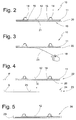
- FIG. 2 a section through the intermediate product 10 in a sectional view approximately according to the view arrows II in Fig. 1d but with the omission of two straight pipe sections. Accordingly, in Fig. 2
- the pipe sections 14 are evidenced Fig. 2 in cross-section D-shaped and are fixed by the heat conducting plates 16, in the present embodiment on both sides, on the front side 12 of the support plate 11.
- Fig. 2 illustrates further that on the back or bottom 19 of the support plate 11, an adhesive layer 20 is arranged, which is covered by a protective layer 21, in particular the entire surface.
- the protective layer 21 serves, in particular, for easier handling of the intermediate product 10 and easier transport, in the sense that the intermediate product 10 does not stick to another object due to the adhesive layer 20 during transport.
- This in Fig. 2 shown intermediate product 10 is now already in a second location, which may be, for example, the mounting location, so for example, the building space in which the surface heat exchanger to be installed.
- a second location may be, for example, the mounting location, so for example, the building space in which the surface heat exchanger to be installed.
- the second location may also differ slightly from the place of installation.
- the finished intermediate product 10 according to Fig. 2 From the locality of the manufacturer are first transported to a locality of a mechanic, which is located near the assembly site.
- the protective layer 21 or protective film 21 can be easily removed or removed manually. In this way, the adhesive layer 20 of the intermediate product 10 is exposed. A user can manually engage behind a gripping surface 18 of the protective layer 21.
- a black color impression can then result when the underside of the carrier plate 11 is viewed.
- This can be produced for example by a black-colored adhesive layer 20, or in an alternative, not shown embodiment by a separate coating of the underside of the support plate 11, which would thus be arranged between the support plate 11 and the adhesive layer 20, in which case a substantially transparent adhesive layer is to be used.
- the removal of the protective layer 21 according to Fig. 3 is preferably carried out immediately prior to sticking the remainder 22 of the intermediate product in or on a holding cassette 23, as in Fig. 4 is shown.
- the remainder 22 of the intermediate product 10, in particular comprising the exposed adhesive layer 20, the carrier plate 11 and the tube system 13 and the heat conducting plates 16, can then be approximated along an insertion direction E to the inside 24 of the holding cassette and there with the help of the exposed adhesive layer 20, in particular the entire surface to be glued.
- This bonding takes place substantially plane-parallel, by bringing the plate plane P plane-parallel to the mounting plane B of the holding cassette 23 until it a mounting surface 25 of the holding cassette 23 glued.
- no tools, tools or the like are usually necessary.
- a user can do this manually, in particular by after applying the remainder 22 of the intermediate product 10 in or on the holding cassette 23 or the attachment surface 25 exerts pressure approximately along the insertion direction E on the back 24 of the carrier plate.
- the finished surface heat exchanger is then in Fig. 5 designated by the reference numeral 26.
- FIGS. 4 and 5 not shown is another embodiment, which provides that the mounting surface 25 of the holding cassette 23 is provided by a arranged in the holding cassette, preferably black fleece.
- This optional nonwoven has, inter alia, acoustic and optical properties and may already be introduced into the cassette 23 in a separate method step.
- the surface heat exchanger 26 can now be spent from the second location, for example, the location of the local mechanic to the installation site, in particular the proposed building space. If the completion of the surface heat exchanger 26, however, already at the installation site, it can now (evidently Fig. 6 ) the final assembly of the finished surface heat exchanger 26 done.
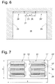
- Fig. 6 shows the surface heat exchanger 26 in a fully assembled state, including the surface heat exchanger 26 was attached or fixed to a ceiling 27 of a building room 28.
- the surface heat exchanger 26 in Fig. 6 but only the holding cassette without the rest 22 of the intermediate product 10 is shown.
- the finished surface-mounted heat exchanger 26 but includes all in Fig. 5 illustrated components.
- the holding cassette 23 For mounting the surface heat exchanger 26, the holding cassette 23, for example, in Fig. 6 indicated, and in Fig. 5 omitted for clarity sake, mounting surfaces, which in particular to the side edges 29 of the holding cassette 23 (see. Fig. 5 ).
- the surface heat exchanger 26 is in Fig. 6 together with other surface heat exchangers 26 'and 26 "cascade mounted on the ceiling 27. For complete assembly, it is inter alia that the surface heat exchanger 26 is connected with respect to its pipe system with the other surface heat exchangers 26' and / or 26", thus a continuous line of a the pipe system 13 flowing fluid is secured to the ceiling 27.
- Fig. 6 It should be noted that on the ceiling of course much more or less than three of the illustrated surface heat exchangers can be used.
- the surface heat exchanger can not only, as shown in the sectional view Fig. 6 shown, next to each other but also with respect to the other spatial direction to be arranged one behind the other.
- the surface heat exchanger 26 form a so-called climatic ceiling, which provides for air conditioning of the room 28. If the pipe systems or the pipe system are traversed by a cooling medium, for example cooled or cool water, the air-conditioning ceiling can have a cooling effect. If the space 28, however, be warmed, the pipe systems 13 of the Surface heat exchanger 26 with heated medium, such as hot water to flow through.
- a cooling medium for example cooled or cool water
- a typical surface heat exchanger 26 has a width b of about 60 cm, in particular between 50 and 70 cm. In the other spatial direction of the surface heat exchanger 26 may have an identical dimension or alternatively typically also about twice as long dimension, so a length I of about 120 cm or more preferably between 100 cm and 140 cm.
- exactly one intermediate product (rest) 22 is arranged within a holding cassette or an intermediate product is installed.
- Fig. 7 shows another embodiment of a built-surface heat exchanger in which the length of the holding cassette 23 'is about twice as long as the width, that is about at a length I of 1.20 m and a width B of about 60 cm.
- two substantially identical residues 22 'of intermediates 10' are then attached side by side.
- FIG. 7 Another alternative embodiment shows Fig. 7 also to the effect that the units or remainders 22 each have a different design of the carrier plate 11 'in comparison to the carrier plate 11 according to FIG Fig. 1d Namely, in particular, the bent portions 15 'of the pipe system 13' on the actual support plate 11 'laterally over. This embodiment may vary depending on the customer's wishes.
- the carrier plates 11 'in Fig. 7 have a so-called acoustic perforation 30.
- This acoustic perforation can serve for improved acoustics and, in particular, with the corresponding, in Fig. 7 unrecognizable, acoustic perforation in the mounting surface 25 of the holding cassette 23 'go along.
- the acoustic perforations in the holding cassette 23 'and in the carrier plates 11' can thus be brought together substantially congruent during assembly.
- the adhesive layer on the support plate 11 'for mounting on the mounting surface of the holding cassette 23' releases the acoustic perforations, if necessary. In this sense, the adhesive layer may have a congruent perforation or congruent openings or omissions.
- the adhesive layer in the sense of the present patent application still has to be regarded as a substantially continuous adhesive layer, which is adhered substantially to the entire surface of the inside of the holding cassette 23 '.
- acoustic perforations can also be provided in variants in which only a remainder of an intermediate product or an intermediate product is used to produce a surface heat exchanger.
Landscapes
- Engineering & Computer Science (AREA)
- Mechanical Engineering (AREA)
- Chemical & Material Sciences (AREA)
- Combustion & Propulsion (AREA)
- General Engineering & Computer Science (AREA)
- Life Sciences & Earth Sciences (AREA)
- Sustainable Development (AREA)
- Physics & Mathematics (AREA)
- Fluid Mechanics (AREA)
- Thermal Sciences (AREA)
- Heat-Exchange Devices With Radiators And Conduit Assemblies (AREA)
Priority Applications (1)
| Application Number | Priority Date | Filing Date | Title |
|---|---|---|---|
| PL16001406T PL3109559T3 (pl) | 2015-06-25 | 2016-06-23 | Sposób i system oraz produkt pośredni dla instalacji klimatyzacji przestrzeni budynku |
Applications Claiming Priority (1)
| Application Number | Priority Date | Filing Date | Title |
|---|---|---|---|
| DE102015008082.2A DE102015008082B4 (de) | 2015-06-25 | 2015-06-25 | Verfahren und System sowie Zwischenprodukt zur Einrichtung einer Gebäuderaumklimatisierung |
Publications (2)
| Publication Number | Publication Date |
|---|---|
| EP3109559A1 true EP3109559A1 (fr) | 2016-12-28 |
| EP3109559B1 EP3109559B1 (fr) | 2020-08-05 |
Family
ID=57348374
Family Applications (1)
| Application Number | Title | Priority Date | Filing Date |
|---|---|---|---|
| EP16001406.4A Active EP3109559B1 (fr) | 2015-06-25 | 2016-06-23 | Procede et systeme et produit intermediaire destine a creer une climatisation de batiment |
Country Status (5)
| Country | Link |
|---|---|
| EP (1) | EP3109559B1 (fr) |
| DE (1) | DE102015008082B4 (fr) |
| DK (1) | DK3109559T3 (fr) |
| ES (1) | ES2822564T3 (fr) |
| PL (1) | PL3109559T3 (fr) |
Cited By (1)
| Publication number | Priority date | Publication date | Assignee | Title |
|---|---|---|---|---|
| WO2019034789A3 (fr) * | 2017-08-18 | 2019-04-18 | Ullrich Buff | Élément échangeur de chaleur et son procédé de fabrication, panneau de construction et procédé de déshumidification de l'air |
Families Citing this family (2)
| Publication number | Priority date | Publication date | Assignee | Title |
|---|---|---|---|---|
| DE202021100591U1 (de) | 2021-02-05 | 2022-05-06 | Schmöle GmbH | Zwischenprodukt für die Herstellung eines Flächenwärmetauschers und selbiger |
| DE102021117454A1 (de) | 2021-07-06 | 2023-01-12 | Schmöle GmbH | Vorrichtung und Verfahren zur Wärmerückgewinnung bei Nutzwasser |
Citations (2)
| Publication number | Priority date | Publication date | Assignee | Title |
|---|---|---|---|---|
| EP0769659A1 (fr) * | 1995-10-06 | 1997-04-23 | Barcol-Air Ag | Elément de contact et élément de plafond pour chauffage ou refroidissement par le plafond |
| CH707238A1 (de) * | 2012-11-23 | 2014-05-30 | Barcol Air | Heiz- oder Kühlelement. |
Family Cites Families (8)
| Publication number | Priority date | Publication date | Assignee | Title |
|---|---|---|---|---|
| DE19540770C2 (de) * | 1995-11-02 | 1998-04-16 | Krantz Tkt Gmbh | Kühldeckenelement |
| DE19850013B4 (de) * | 1998-10-30 | 2008-09-11 | KME Schmöle GmbH | Plattenförmiges Wärmeaustauscherelement |
| DE10257103A1 (de) * | 2002-12-05 | 2004-06-17 | KME Schmöle GmbH | Wärmeaustauscherelement |
| DE10311214A1 (de) * | 2003-03-14 | 2004-09-23 | Jolly, Jürgen | Raumkühlungssystem |
| DE202005004216U1 (de) * | 2005-03-14 | 2006-07-27 | Uponor Innovation Ab | Heiz- und/oder Kühlelement für eine ein Ständerwerk aufweisende Trockenbauwand |
| DE202010015951U1 (de) * | 2010-11-30 | 2011-02-03 | Schmöle GmbH | Flächenwärmetauscherelement |
| DE202013003763U1 (de) * | 2013-04-20 | 2013-06-13 | BeKa Heiz- und Kühlmatten GmbH | Rohrmattenanordnung zum Heizen oder Kühlen einer Klimadecke |
| DE102015003280B4 (de) * | 2015-03-16 | 2021-07-15 | Schmöle GmbH | Flächenwärmetauscher und Verfahren zu dessen Bereitstellung |
-
2015
- 2015-06-25 DE DE102015008082.2A patent/DE102015008082B4/de active Active
-
2016
- 2016-06-23 DK DK16001406.4T patent/DK3109559T3/da active
- 2016-06-23 EP EP16001406.4A patent/EP3109559B1/fr active Active
- 2016-06-23 PL PL16001406T patent/PL3109559T3/pl unknown
- 2016-06-23 ES ES16001406T patent/ES2822564T3/es active Active
Patent Citations (2)
| Publication number | Priority date | Publication date | Assignee | Title |
|---|---|---|---|---|
| EP0769659A1 (fr) * | 1995-10-06 | 1997-04-23 | Barcol-Air Ag | Elément de contact et élément de plafond pour chauffage ou refroidissement par le plafond |
| CH707238A1 (de) * | 2012-11-23 | 2014-05-30 | Barcol Air | Heiz- oder Kühlelement. |
Cited By (3)
| Publication number | Priority date | Publication date | Assignee | Title |
|---|---|---|---|---|
| WO2019034789A3 (fr) * | 2017-08-18 | 2019-04-18 | Ullrich Buff | Élément échangeur de chaleur et son procédé de fabrication, panneau de construction et procédé de déshumidification de l'air |
| US20200232663A1 (en) * | 2017-08-18 | 2020-07-23 | Ullrich Buff | Heat exchanger element and method for its manufacture; building panel and method for dehumidifying air |
| US11549698B2 (en) * | 2017-08-18 | 2023-01-10 | Ullrich Buff | Heat exchanger element and method for its manufacture; building panel and method for dehumidifying air |
Also Published As
| Publication number | Publication date |
|---|---|
| EP3109559B1 (fr) | 2020-08-05 |
| PL3109559T3 (pl) | 2021-02-08 |
| DE102015008082B4 (de) | 2024-12-24 |
| ES2822564T3 (es) | 2021-05-04 |
| DE102015008082A1 (de) | 2016-12-29 |
| DK3109559T3 (da) | 2020-11-09 |
Similar Documents
| Publication | Publication Date | Title |
|---|---|---|
| DE102010018162B3 (de) | Verfahren zur Herstellung eines Flächenwärmetauschelementes u.a. | |
| DE202018102124U1 (de) | Wärmetauscherelement | |
| EP2765366B1 (fr) | Élément d'échangeur de chaleur à surface raclée, procédé de fabrication d'un élément d'échangeur de chaleur à surface raclée et outil | |
| EP3109559B1 (fr) | Procede et systeme et produit intermediaire destine a creer une climatisation de batiment | |
| EP1426721B1 (fr) | Element d'échangeur de chaleur | |
| DE202010015951U1 (de) | Flächenwärmetauscherelement | |
| EP2975329B1 (fr) | Structure de surfaces rayonnantes et son procede de fabrication | |
| EP2565338A1 (fr) | Élément en forme de plaque pour systèmes de refroidissement ou de chauffage | |
| DE102023102028A1 (de) | Wärmeleitblech und Vefahren zur Herstellung eines solchen | |
| DE102013012644A1 (de) | Beschichtungsvorrichtung sowie Aktivierungsmodul für eine Beschichtungsvorrichtung | |
| EP4040051B1 (fr) | Produit intermédiaire pour la fabrication d'un échangeur de chaleur plan et échangeur de chaleur plan | |
| DE102013208284A1 (de) | Wärmedämmplatte und Verfahren zur Montage von Leitungen | |
| DE102015003280B4 (de) | Flächenwärmetauscher und Verfahren zu dessen Bereitstellung | |
| EP4375604B1 (fr) | Échangeur de chaleur à ailettes, son procédé de fabrication et système | |
| DE19850013B4 (de) | Plattenförmiges Wärmeaustauscherelement | |
| EP2762787A2 (fr) | Élément climatique pour un plafond chauffant et refroidissant | |
| DE19641179C1 (de) | Verfahren zum Befestigen von flexiblen Röhrchen an einem Bauwerkteil | |
| EP1482258A1 (fr) | Evaporateur du type tubulaire ainsi que procédé et dispositif de fabrication de celui-ci | |
| WO2005050108A1 (fr) | Evaporateur pour refrigerateur et/ou congelateur | |
| DE102015003279B4 (de) | Flächenwärmetauscher und Verfahren zu dessen Herstellung | |
| DE102017130090A1 (de) | Vorrichtung sowie Verfahren zum Temperieren eines Raumes | |
| CH619643A5 (en) | Process for producing a laminated material | |
| EP4202341A2 (fr) | Ailettes d'échangeur de chaleur et leur procédé de fabrication | |
| DE102023116217A1 (de) | Verfahren zum Herstellen einer Klimadecke oder -Wand und Flächenwärmetauscher | |
| EP3425313A1 (fr) | Appareil frigorifique |
Legal Events
| Date | Code | Title | Description |
|---|---|---|---|
| PUAI | Public reference made under article 153(3) epc to a published international application that has entered the european phase |
Free format text: ORIGINAL CODE: 0009012 |
|
| STAA | Information on the status of an ep patent application or granted ep patent |
Free format text: STATUS: THE APPLICATION HAS BEEN PUBLISHED |
|
| AK | Designated contracting states |
Kind code of ref document: A1 Designated state(s): AL AT BE BG CH CY CZ DE DK EE ES FI FR GB GR HR HU IE IS IT LI LT LU LV MC MK MT NL NO PL PT RO RS SE SI SK SM TR |
|
| AX | Request for extension of the european patent |
Extension state: BA ME |
|
| STAA | Information on the status of an ep patent application or granted ep patent |
Free format text: STATUS: REQUEST FOR EXAMINATION WAS MADE |
|
| 17P | Request for examination filed |
Effective date: 20170622 |
|
| RBV | Designated contracting states (corrected) |
Designated state(s): AL AT BE BG CH CY CZ DE DK EE ES FI FR GB GR HR HU IE IS IT LI LT LU LV MC MK MT NL NO PL PT RO RS SE SI SK SM TR |
|
| STAA | Information on the status of an ep patent application or granted ep patent |
Free format text: STATUS: EXAMINATION IS IN PROGRESS |
|
| 17Q | First examination report despatched |
Effective date: 20190321 |
|
| GRAP | Despatch of communication of intention to grant a patent |
Free format text: ORIGINAL CODE: EPIDOSNIGR1 |
|
| STAA | Information on the status of an ep patent application or granted ep patent |
Free format text: STATUS: GRANT OF PATENT IS INTENDED |
|
| INTG | Intention to grant announced |
Effective date: 20200408 |
|
| GRAS | Grant fee paid |
Free format text: ORIGINAL CODE: EPIDOSNIGR3 |
|
| GRAA | (expected) grant |
Free format text: ORIGINAL CODE: 0009210 |
|
| STAA | Information on the status of an ep patent application or granted ep patent |
Free format text: STATUS: THE PATENT HAS BEEN GRANTED |
|
| AK | Designated contracting states |
Kind code of ref document: B1 Designated state(s): AL AT BE BG CH CY CZ DE DK EE ES FI FR GB GR HR HU IE IS IT LI LT LU LV MC MK MT NL NO PL PT RO RS SE SI SK SM TR |
|
| REG | Reference to a national code |
Ref country code: GB Ref legal event code: FG4D Free format text: NOT ENGLISH |
|
| REG | Reference to a national code |
Ref country code: CH Ref legal event code: EP |
|
| REG | Reference to a national code |
Ref country code: AT Ref legal event code: REF Ref document number: 1299240 Country of ref document: AT Kind code of ref document: T Effective date: 20200815 |
|
| REG | Reference to a national code |
Ref country code: DE Ref legal event code: R096 Ref document number: 502016010690 Country of ref document: DE |
|
| REG | Reference to a national code |
Ref country code: IE Ref legal event code: FG4D Free format text: LANGUAGE OF EP DOCUMENT: GERMAN |
|
| REG | Reference to a national code |
Ref country code: CH Ref legal event code: NV Representative=s name: E. BLUM AND CO. AG PATENT- UND MARKENANWAELTE , CH |
|
| REG | Reference to a national code |
Ref country code: FI Ref legal event code: FGE |
|
| REG | Reference to a national code |
Ref country code: SE Ref legal event code: TRGR |
|
| REG | Reference to a national code |
Ref country code: DK Ref legal event code: T3 Effective date: 20201104 |
|
| REG | Reference to a national code |
Ref country code: NL Ref legal event code: FP |
|
| REG | Reference to a national code |
Ref country code: LT Ref legal event code: MG4D |
|
| PG25 | Lapsed in a contracting state [announced via postgrant information from national office to epo] |
Ref country code: GR Free format text: LAPSE BECAUSE OF FAILURE TO SUBMIT A TRANSLATION OF THE DESCRIPTION OR TO PAY THE FEE WITHIN THE PRESCRIBED TIME-LIMIT Effective date: 20201106 Ref country code: PT Free format text: LAPSE BECAUSE OF FAILURE TO SUBMIT A TRANSLATION OF THE DESCRIPTION OR TO PAY THE FEE WITHIN THE PRESCRIBED TIME-LIMIT Effective date: 20201207 Ref country code: NO Free format text: LAPSE BECAUSE OF FAILURE TO SUBMIT A TRANSLATION OF THE DESCRIPTION OR TO PAY THE FEE WITHIN THE PRESCRIBED TIME-LIMIT Effective date: 20201105 Ref country code: HR Free format text: LAPSE BECAUSE OF FAILURE TO SUBMIT A TRANSLATION OF THE DESCRIPTION OR TO PAY THE FEE WITHIN THE PRESCRIBED TIME-LIMIT Effective date: 20200805 Ref country code: LT Free format text: LAPSE BECAUSE OF FAILURE TO SUBMIT A TRANSLATION OF THE DESCRIPTION OR TO PAY THE FEE WITHIN THE PRESCRIBED TIME-LIMIT Effective date: 20200805 Ref country code: BG Free format text: LAPSE BECAUSE OF FAILURE TO SUBMIT A TRANSLATION OF THE DESCRIPTION OR TO PAY THE FEE WITHIN THE PRESCRIBED TIME-LIMIT Effective date: 20201105 |
|
| PG25 | Lapsed in a contracting state [announced via postgrant information from national office to epo] |
Ref country code: LV Free format text: LAPSE BECAUSE OF FAILURE TO SUBMIT A TRANSLATION OF THE DESCRIPTION OR TO PAY THE FEE WITHIN THE PRESCRIBED TIME-LIMIT Effective date: 20200805 Ref country code: RS Free format text: LAPSE BECAUSE OF FAILURE TO SUBMIT A TRANSLATION OF THE DESCRIPTION OR TO PAY THE FEE WITHIN THE PRESCRIBED TIME-LIMIT Effective date: 20200805 Ref country code: IS Free format text: LAPSE BECAUSE OF FAILURE TO SUBMIT A TRANSLATION OF THE DESCRIPTION OR TO PAY THE FEE WITHIN THE PRESCRIBED TIME-LIMIT Effective date: 20201205 |
|
| PG25 | Lapsed in a contracting state [announced via postgrant information from national office to epo] |
Ref country code: CZ Free format text: LAPSE BECAUSE OF FAILURE TO SUBMIT A TRANSLATION OF THE DESCRIPTION OR TO PAY THE FEE WITHIN THE PRESCRIBED TIME-LIMIT Effective date: 20200805 Ref country code: EE Free format text: LAPSE BECAUSE OF FAILURE TO SUBMIT A TRANSLATION OF THE DESCRIPTION OR TO PAY THE FEE WITHIN THE PRESCRIBED TIME-LIMIT Effective date: 20200805 Ref country code: RO Free format text: LAPSE BECAUSE OF FAILURE TO SUBMIT A TRANSLATION OF THE DESCRIPTION OR TO PAY THE FEE WITHIN THE PRESCRIBED TIME-LIMIT Effective date: 20200805 Ref country code: SM Free format text: LAPSE BECAUSE OF FAILURE TO SUBMIT A TRANSLATION OF THE DESCRIPTION OR TO PAY THE FEE WITHIN THE PRESCRIBED TIME-LIMIT Effective date: 20200805 |
|
| REG | Reference to a national code |
Ref country code: ES Ref legal event code: FG2A Ref document number: 2822564 Country of ref document: ES Kind code of ref document: T3 Effective date: 20210504 |
|
| REG | Reference to a national code |
Ref country code: DE Ref legal event code: R097 Ref document number: 502016010690 Country of ref document: DE |
|
| PG25 | Lapsed in a contracting state [announced via postgrant information from national office to epo] |
Ref country code: AL Free format text: LAPSE BECAUSE OF FAILURE TO SUBMIT A TRANSLATION OF THE DESCRIPTION OR TO PAY THE FEE WITHIN THE PRESCRIBED TIME-LIMIT Effective date: 20200805 |
|
| PLBE | No opposition filed within time limit |
Free format text: ORIGINAL CODE: 0009261 |
|
| STAA | Information on the status of an ep patent application or granted ep patent |
Free format text: STATUS: NO OPPOSITION FILED WITHIN TIME LIMIT |
|
| PG25 | Lapsed in a contracting state [announced via postgrant information from national office to epo] |
Ref country code: SK Free format text: LAPSE BECAUSE OF FAILURE TO SUBMIT A TRANSLATION OF THE DESCRIPTION OR TO PAY THE FEE WITHIN THE PRESCRIBED TIME-LIMIT Effective date: 20200805 |
|
| 26N | No opposition filed |
Effective date: 20210507 |
|
| PG25 | Lapsed in a contracting state [announced via postgrant information from national office to epo] |
Ref country code: SI Free format text: LAPSE BECAUSE OF FAILURE TO SUBMIT A TRANSLATION OF THE DESCRIPTION OR TO PAY THE FEE WITHIN THE PRESCRIBED TIME-LIMIT Effective date: 20200805 |
|
| PG25 | Lapsed in a contracting state [announced via postgrant information from national office to epo] |
Ref country code: MC Free format text: LAPSE BECAUSE OF FAILURE TO SUBMIT A TRANSLATION OF THE DESCRIPTION OR TO PAY THE FEE WITHIN THE PRESCRIBED TIME-LIMIT Effective date: 20200805 |
|
| PG25 | Lapsed in a contracting state [announced via postgrant information from national office to epo] |
Ref country code: HU Free format text: LAPSE BECAUSE OF FAILURE TO SUBMIT A TRANSLATION OF THE DESCRIPTION OR TO PAY THE FEE WITHIN THE PRESCRIBED TIME-LIMIT; INVALID AB INITIO Effective date: 20160623 |
|
| PG25 | Lapsed in a contracting state [announced via postgrant information from national office to epo] |
Ref country code: CY Free format text: LAPSE BECAUSE OF FAILURE TO SUBMIT A TRANSLATION OF THE DESCRIPTION OR TO PAY THE FEE WITHIN THE PRESCRIBED TIME-LIMIT Effective date: 20200805 |
|
| P01 | Opt-out of the competence of the unified patent court (upc) registered |
Effective date: 20230530 |
|
| PGFP | Annual fee paid to national office [announced via postgrant information from national office to epo] |
Ref country code: NL Payment date: 20230620 Year of fee payment: 8 Ref country code: IE Payment date: 20230613 Year of fee payment: 8 |
|
| PGFP | Annual fee paid to national office [announced via postgrant information from national office to epo] |
Ref country code: PL Payment date: 20230612 Year of fee payment: 8 Ref country code: LU Payment date: 20230619 Year of fee payment: 8 |
|
| PG25 | Lapsed in a contracting state [announced via postgrant information from national office to epo] |
Ref country code: MK Free format text: LAPSE BECAUSE OF FAILURE TO SUBMIT A TRANSLATION OF THE DESCRIPTION OR TO PAY THE FEE WITHIN THE PRESCRIBED TIME-LIMIT Effective date: 20200805 |
|
| PG25 | Lapsed in a contracting state [announced via postgrant information from national office to epo] |
Ref country code: TR Free format text: LAPSE BECAUSE OF FAILURE TO SUBMIT A TRANSLATION OF THE DESCRIPTION OR TO PAY THE FEE WITHIN THE PRESCRIBED TIME-LIMIT Effective date: 20200805 |
|
| PGFP | Annual fee paid to national office [announced via postgrant information from national office to epo] |
Ref country code: SE Payment date: 20240620 Year of fee payment: 9 |
|
| PG25 | Lapsed in a contracting state [announced via postgrant information from national office to epo] |
Ref country code: MT Free format text: LAPSE BECAUSE OF FAILURE TO SUBMIT A TRANSLATION OF THE DESCRIPTION OR TO PAY THE FEE WITHIN THE PRESCRIBED TIME-LIMIT Effective date: 20200805 |
|
| PGFP | Annual fee paid to national office [announced via postgrant information from national office to epo] |
Ref country code: IT Payment date: 20240628 Year of fee payment: 9 |
|
| REG | Reference to a national code |
Ref country code: NL Ref legal event code: MM Effective date: 20240701 |
|
| PG25 | Lapsed in a contracting state [announced via postgrant information from national office to epo] |
Ref country code: LU Free format text: LAPSE BECAUSE OF NON-PAYMENT OF DUE FEES Effective date: 20240623 |
|
| PG25 | Lapsed in a contracting state [announced via postgrant information from national office to epo] |
Ref country code: NL Free format text: LAPSE BECAUSE OF NON-PAYMENT OF DUE FEES Effective date: 20240701 |
|
| PG25 | Lapsed in a contracting state [announced via postgrant information from national office to epo] |
Ref country code: NL Free format text: LAPSE BECAUSE OF NON-PAYMENT OF DUE FEES Effective date: 20240701 |
|
| PG25 | Lapsed in a contracting state [announced via postgrant information from national office to epo] |
Ref country code: IE Free format text: LAPSE BECAUSE OF NON-PAYMENT OF DUE FEES Effective date: 20240623 |
|
| PGFP | Annual fee paid to national office [announced via postgrant information from national office to epo] |
Ref country code: FI Payment date: 20250617 Year of fee payment: 10 |
|
| PGFP | Annual fee paid to national office [announced via postgrant information from national office to epo] |
Ref country code: DK Payment date: 20250613 Year of fee payment: 10 |
|
| PGFP | Annual fee paid to national office [announced via postgrant information from national office to epo] |
Ref country code: ES Payment date: 20250718 Year of fee payment: 10 |
|
| PGFP | Annual fee paid to national office [announced via postgrant information from national office to epo] |
Ref country code: DE Payment date: 20250627 Year of fee payment: 10 |
|
| PG25 | Lapsed in a contracting state [announced via postgrant information from national office to epo] |
Ref country code: PL Free format text: LAPSE BECAUSE OF NON-PAYMENT OF DUE FEES Effective date: 20240623 |
|
| PGFP | Annual fee paid to national office [announced via postgrant information from national office to epo] |
Ref country code: BE Payment date: 20250722 Year of fee payment: 10 Ref country code: GB Payment date: 20250724 Year of fee payment: 10 |
|
| PGFP | Annual fee paid to national office [announced via postgrant information from national office to epo] |
Ref country code: FR Payment date: 20250718 Year of fee payment: 10 Ref country code: AT Payment date: 20250721 Year of fee payment: 10 |
|
| PGFP | Annual fee paid to national office [announced via postgrant information from national office to epo] |
Ref country code: CH Payment date: 20250724 Year of fee payment: 10 |
|
| REG | Reference to a national code |
Ref country code: SE Ref legal event code: EUG |
|
| PG25 | Lapsed in a contracting state [announced via postgrant information from national office to epo] |
Ref country code: IT Free format text: LAPSE BECAUSE OF NON-PAYMENT OF DUE FEES Effective date: 20250623 |