EP3109880A1 - Mittel- oder hochspannungspolteil mit wenigstens einem kühlkörperelement - Google Patents
Mittel- oder hochspannungspolteil mit wenigstens einem kühlkörperelement Download PDFInfo
- Publication number
- EP3109880A1 EP3109880A1 EP15173142.9A EP15173142A EP3109880A1 EP 3109880 A1 EP3109880 A1 EP 3109880A1 EP 15173142 A EP15173142 A EP 15173142A EP 3109880 A1 EP3109880 A1 EP 3109880A1
- Authority
- EP
- European Patent Office
- Prior art keywords
- heat sink
- pole part
- shaped
- sink element
- high voltage
- Prior art date
- Legal status (The legal status is an assumption and is not a legal conclusion. Google has not performed a legal analysis and makes no representation as to the accuracy of the status listed.)
- Withdrawn
Links
Images



Classifications
-
- H—ELECTRICITY
- H01—ELECTRIC ELEMENTS
- H01H—ELECTRIC SWITCHES; RELAYS; SELECTORS; EMERGENCY PROTECTIVE DEVICES
- H01H9/00—Details of switching devices, not covered by groups H01H1/00 - H01H7/00
- H01H9/52—Cooling of switch parts
-
- H—ELECTRICITY
- H01—ELECTRIC ELEMENTS
- H01H—ELECTRIC SWITCHES; RELAYS; SELECTORS; EMERGENCY PROTECTIVE DEVICES
- H01H9/00—Details of switching devices, not covered by groups H01H1/00 - H01H7/00
- H01H9/52—Cooling of switch parts
- H01H2009/523—Cooling of switch parts by using heat pipes
-
- H—ELECTRICITY
- H01—ELECTRIC ELEMENTS
- H01H—ELECTRIC SWITCHES; RELAYS; SELECTORS; EMERGENCY PROTECTIVE DEVICES
- H01H9/00—Details of switching devices, not covered by groups H01H1/00 - H01H7/00
- H01H9/52—Cooling of switch parts
- H01H2009/526—Cooling of switch parts of the high voltage switches
-
- H—ELECTRICITY
- H01—ELECTRIC ELEMENTS
- H01H—ELECTRIC SWITCHES; RELAYS; SELECTORS; EMERGENCY PROTECTIVE DEVICES
- H01H33/00—High-tension or heavy-current switches with arc-extinguishing or arc-preventing means
- H01H33/60—Switches wherein the means for extinguishing or preventing the arc do not include separate means for obtaining or increasing flow of arc-extinguishing fluid
- H01H33/66—Vacuum switches
- H01H33/6606—Terminal arrangements
- H01H2033/6613—Cooling arrangements directly associated with the terminal arrangements
Definitions
- the invention relates to a medium- or high voltage pole part with at least one heat sink element, according to the preamble of claim 1.
- the temperature rise especially in the region of the contact terminal has to be limited.
- a pole part of a circuit breaker arrangement with a heat sink element arranged near the upper electrical contact terminals is disclosed in EP 2 720 244 A1 .
- This heat sink element is additionally heavy and compact with a relatively high mass, in order to fulfill a double function, as a heat sink, and as a bouncing absorber for absorbing shock energy from the movement of the moving contact in the end position.
- the function as heat sink near the upper contact terminal is advantageous, in order to dissipate away the heat, which occurs there by the effect of electrical power loss of electrical conducting part and transition resistance between electrical contacting parts.
- the known heat sink element which is very solid and heavy has its main function, in compensation of bouncing energy. Therefore, the installion is much more complex than necessary.
- the invention is, that the heat sink element is U-shaped in such, that it is mountable by shifting and clamping it on the pole part body, from the contact face side of the pole part.
- heat sink is used on top of the pole part, as shown in the aforesaid EP 2 720 244 A1 .
- heat will be dissipated in a much more effective way, by the contour structures, which are positioned closely at that point of the vacuum interrupter pole part, where heat occurs, for example by electrical transition resistance.
- the assembly of the heat sink elements on the pole part is much easier.
- the heat sink element can be retrofitted much easier.
- a preferably thin U shaped heat sink is fixed to the contact arms of the terminals of the vacuum circuit breaker pole part. This heat sink will get the local power loss dissipated to the surrounding of the pole part of the vacuum circuit breaker.
- multiple plate that means multiple layered structure can be used in order to increase the heat dissipation, like decribed in the following text.
- U-shaped heat pipe can also be used.
- slots, holes, ribs, cubic, cylinder, radius ribs features could be added into this U shaped part in order to enforce the heat dissipation of this part.
- U-shaped heat sink element consist of two opposing flanks which are both fixed at a bottom element, so that the so structured heat sink element is a one piece element. So it surrounds the pole part closely for good heat transition.
- each of the opposing flanks of the U-shaped heat sink element consist of at least two layers arranged spaced apart, and that the at least two layers per flank are fixed at the common bottom element.
- a final advantageous embodiment is, that the bottom element is provided with a c-formed recess in such, that the c-conture of this recess is arrangend partly around the external wall of the electrical contact terminal.
- the Invention is used in vacuum interrupter arrangements in such, that the vacuum interrupter is mounted on a frame, with medium- or high voltage pole parts according to one of the aforesaid claims, wherein the heat sink elements are U-shaped.
- the heat sink elements are provided furthermore with a bridge element at the open side of the U-shape contour, in order to form the heat sink element finally into a O-shaped contour, surrounding the pole part around the main axis.
- a bridge element at the open side of the U-shape contour, in order to form the heat sink element finally into a O-shaped contour, surrounding the pole part around the main axis.
- two U- or L-shaped contour could be fixed together around the contact arm, to form this O-shaped contour.
- the pole part is provided with such heat sink element at both contact terminals, the upper contact terminal and the lower contact terminal.
- a three phase arrangement 1 of three pole parts on a circuit breaker are provided with an U-shaped heat sink element 2 at each electrical contact or terminal arm 3.
- the U-shape is created as such, that the heat sink element can be inserted from the front side, that means from the contact face side of the pole parts of the circuit breaker.
- the U-shaped heat sink element can be fixed to the contact arm of a vacuum circuit breaker pole part. This heat sink will get the local power loss dissipated to the surrounding of the pole part of the vacuum circuit breaker.
- FIG. 2 shows a further detailed heat sink element 2, like defined by the further depending claims in a special advantageous embodiment. So the heat sink element 2 will be inserted on the terminals of the pole part in the same way, like mentioned above. Here is shown, that the flanks of the heat sink element are splitted into two layers 2' and 2" each. This multiplies the active heat emitting or dissipating surface. The fact that the layers are arranged as such, that in the mounted position, a vertically oriented slot will be between the layers, this will support cooling convection between them by normally vertically upstreaming convention of the air.
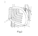
- FIG 3 An alternative, or a combinable further embodiment of the heat sink is shown in figure 3 .
- the flanks are provided with a number of parallel cooling slots 4, which are arrangend here in a L-shape. This also supports cooling by convenction. This slot arrangement can also be combined with the double or multilayered flanks of the heat sink element, as shown in figure 2 .
- U-shaped heat pipe can also be used.
- the contact surface between them should be machined properly with good mechanical fit to each other, which results in low transit thermal resistance.
- Possible heat conductive paste could be also used to have a low thermal restistance in between.
- the surface area should be also dimensioned so, that the heat could be transferred properly.
- Last but not least, painting or coating with an insulating material on the surface of the heat sink elements can be also used for increase the thermal radiation and improve the dielectric performance.
- Figure 4 shows once more in detail an embodiment of the heat sink element 2.
- a half round or better a C-formed recess 5, which is placed over the contact arms 3, like shown in figure 1 .
Landscapes
- High-Tension Arc-Extinguishing Switches Without Spraying Means (AREA)
Priority Applications (2)
| Application Number | Priority Date | Filing Date | Title |
|---|---|---|---|
| EP15173142.9A EP3109880A1 (de) | 2015-06-22 | 2015-06-22 | Mittel- oder hochspannungspolteil mit wenigstens einem kühlkörperelement |
| CN201620620101.3U CN206236604U (zh) | 2015-06-22 | 2016-06-21 | 中压或高压电极部件、真空断路器电极部件以及真空断路器装置 |
Applications Claiming Priority (1)
| Application Number | Priority Date | Filing Date | Title |
|---|---|---|---|
| EP15173142.9A EP3109880A1 (de) | 2015-06-22 | 2015-06-22 | Mittel- oder hochspannungspolteil mit wenigstens einem kühlkörperelement |
Publications (1)
| Publication Number | Publication Date |
|---|---|
| EP3109880A1 true EP3109880A1 (de) | 2016-12-28 |
Family
ID=53488195
Family Applications (1)
| Application Number | Title | Priority Date | Filing Date |
|---|---|---|---|
| EP15173142.9A Withdrawn EP3109880A1 (de) | 2015-06-22 | 2015-06-22 | Mittel- oder hochspannungspolteil mit wenigstens einem kühlkörperelement |
Country Status (2)
| Country | Link |
|---|---|
| EP (1) | EP3109880A1 (de) |
| CN (1) | CN206236604U (de) |
Cited By (1)
| Publication number | Priority date | Publication date | Assignee | Title |
|---|---|---|---|---|
| US11842877B2 (en) | 2021-01-27 | 2023-12-12 | Abb Schweiz Ag | Electric pole part apparatus |
Citations (5)
| Publication number | Priority date | Publication date | Assignee | Title |
|---|---|---|---|---|
| EP1107409A1 (de) * | 1999-12-01 | 2001-06-13 | Kabushiki Kaisha Toshiba | Schalter und dessen Herstellungsverfahren |
| WO2009074016A1 (en) * | 2007-12-07 | 2009-06-18 | Abb Technology Ltd. | Heat dissipating means for circuit-breaker and circuit-breaker with such heat dissipating means |
| EP2418666A1 (de) * | 2010-08-13 | 2012-02-15 | ABB Technology AG | Elektrische Kontakteinheit, insbesondere für einen luftisolierten Mittelspannungsschutzschalter |
| EP2720244A1 (de) | 2012-10-11 | 2014-04-16 | ABB Technology AG | Anschlussteil einer Schutzschalteranordnung mit einem Kühlkörperelement |
| EP2784796A1 (de) * | 2013-03-25 | 2014-10-01 | ABB Technology AG | Gaskühler für eine Mittelspannungs-Schaltanlage |
-
2015
- 2015-06-22 EP EP15173142.9A patent/EP3109880A1/de not_active Withdrawn
-
2016
- 2016-06-21 CN CN201620620101.3U patent/CN206236604U/zh active Active
Patent Citations (5)
| Publication number | Priority date | Publication date | Assignee | Title |
|---|---|---|---|---|
| EP1107409A1 (de) * | 1999-12-01 | 2001-06-13 | Kabushiki Kaisha Toshiba | Schalter und dessen Herstellungsverfahren |
| WO2009074016A1 (en) * | 2007-12-07 | 2009-06-18 | Abb Technology Ltd. | Heat dissipating means for circuit-breaker and circuit-breaker with such heat dissipating means |
| EP2418666A1 (de) * | 2010-08-13 | 2012-02-15 | ABB Technology AG | Elektrische Kontakteinheit, insbesondere für einen luftisolierten Mittelspannungsschutzschalter |
| EP2720244A1 (de) | 2012-10-11 | 2014-04-16 | ABB Technology AG | Anschlussteil einer Schutzschalteranordnung mit einem Kühlkörperelement |
| EP2784796A1 (de) * | 2013-03-25 | 2014-10-01 | ABB Technology AG | Gaskühler für eine Mittelspannungs-Schaltanlage |
Cited By (1)
| Publication number | Priority date | Publication date | Assignee | Title |
|---|---|---|---|---|
| US11842877B2 (en) | 2021-01-27 | 2023-12-12 | Abb Schweiz Ag | Electric pole part apparatus |
Also Published As
| Publication number | Publication date |
|---|---|
| CN206236604U (zh) | 2017-06-09 |
Similar Documents
| Publication | Publication Date | Title |
|---|---|---|
| US9767978B1 (en) | Medium voltage breaker conductor with an electrically efficient contour | |
| US20060102618A1 (en) | High voltage ciruit breaker with cooling | |
| KR20110041439A (ko) | 중간-전압 또는 고전압 개폐기 조립체의 극 부분, 및 그 제작 방법 | |
| US20100181291A1 (en) | Pole part of a medium-voltage switching device | |
| EP2658359B1 (de) | Thermische Trennung der Kühlkörperrippen eines elektronischen Steuerungsgehäuses | |
| EP3334254B1 (de) | Elektrischer treiber und beleuchtungsvorrichtung | |
| US7881033B2 (en) | High-voltage system and high-power circuit breaker with cooling | |
| US20050007742A1 (en) | High-power switchgear with cooling rib arrangement | |
| KR101072419B1 (ko) | 진공 회로 차단기 | |
| EP3038152A1 (de) | Leiterplatte und halbleitergehäuse mit leiterplatte | |
| US10056740B2 (en) | Gas cooler for a medium voltage switchgear assembly | |
| JP5868501B2 (ja) | 開閉器ユニットまたはスイッチギヤ | |
| US20100134983A1 (en) | Electric memory module with cooling bodies | |
| EP3109880A1 (de) | Mittel- oder hochspannungspolteil mit wenigstens einem kühlkörperelement | |
| EP2983261A1 (de) | Stromschiene mit integrierter Wärmerohr | |
| WO2016047174A1 (ja) | 電力変換装置 | |
| CN111630619A (zh) | 高压功率开关和用于将真空开关管固持在高压功率开关中的方法 | |
| US10939586B2 (en) | Heat exchanger structure for a rack assembly | |
| CN106300175B (zh) | 穿壁套管散热结构及使用该结构的开关设备 | |
| CA2633906C (en) | Arrangement having at least one electronic component | |
| JP4781178B2 (ja) | 電力用開閉装置 | |
| US10163546B2 (en) | Field control device and high-voltage system having a field control device | |
| KR102515088B1 (ko) | 반도체소자 조립체 | |
| CN205993047U (zh) | 低电阻紧凑型电子开关组件 | |
| US11528799B2 (en) | Backplane and method for producing same |
Legal Events
| Date | Code | Title | Description |
|---|---|---|---|
| PUAI | Public reference made under article 153(3) epc to a published international application that has entered the european phase |
Free format text: ORIGINAL CODE: 0009012 |
|
| STAA | Information on the status of an ep patent application or granted ep patent |
Free format text: STATUS: THE APPLICATION HAS BEEN PUBLISHED |
|
| AK | Designated contracting states |
Kind code of ref document: A1 Designated state(s): AL AT BE BG CH CY CZ DE DK EE ES FI FR GB GR HR HU IE IS IT LI LT LU LV MC MK MT NL NO PL PT RO RS SE SI SK SM TR |
|
| AX | Request for extension of the european patent |
Extension state: BA ME |
|
| STAA | Information on the status of an ep patent application or granted ep patent |
Free format text: STATUS: REQUEST FOR EXAMINATION WAS MADE |
|
| 17P | Request for examination filed |
Effective date: 20170628 |
|
| RBV | Designated contracting states (corrected) |
Designated state(s): AL AT BE BG CH CY CZ DE DK EE ES FI FR GB GR HR HU IE IS IT LI LT LU LV MC MK MT NL NO PL PT RO RS SE SI SK SM TR |
|
| STAA | Information on the status of an ep patent application or granted ep patent |
Free format text: STATUS: EXAMINATION IS IN PROGRESS |
|
| 17Q | First examination report despatched |
Effective date: 20210225 |
|
| STAA | Information on the status of an ep patent application or granted ep patent |
Free format text: STATUS: THE APPLICATION IS DEEMED TO BE WITHDRAWN |
|
| 18D | Application deemed to be withdrawn |
Effective date: 20230214 |