EP3110232B1 - Induktionswärmegarvorrichtung und verfahren zur ansteuerung davon - Google Patents
Induktionswärmegarvorrichtung und verfahren zur ansteuerung davon Download PDFInfo
- Publication number
- EP3110232B1 EP3110232B1 EP16173663.2A EP16173663A EP3110232B1 EP 3110232 B1 EP3110232 B1 EP 3110232B1 EP 16173663 A EP16173663 A EP 16173663A EP 3110232 B1 EP3110232 B1 EP 3110232B1
- Authority
- EP
- European Patent Office
- Prior art keywords
- heating coil
- switching element
- switching elements
- controls
- operated
- Prior art date
- Legal status (The legal status is an assumption and is not a legal conclusion. Google has not performed a legal analysis and makes no representation as to the accuracy of the status listed.)
- Active
Links
Images



Classifications
-
- H—ELECTRICITY
- H05—ELECTRIC TECHNIQUES NOT OTHERWISE PROVIDED FOR
- H05B—ELECTRIC HEATING; ELECTRIC LIGHT SOURCES NOT OTHERWISE PROVIDED FOR; CIRCUIT ARRANGEMENTS FOR ELECTRIC LIGHT SOURCES, IN GENERAL
- H05B6/00—Heating by electric, magnetic or electromagnetic fields
- H05B6/02—Induction heating
- H05B6/06—Control, e.g. of temperature, of power
- H05B6/062—Control, e.g. of temperature, of power for cooking plates or the like
- H05B6/065—Control, e.g. of temperature, of power for cooking plates or the like using coordinated control of multiple induction coils
-
- H—ELECTRICITY
- H05—ELECTRIC TECHNIQUES NOT OTHERWISE PROVIDED FOR
- H05B—ELECTRIC HEATING; ELECTRIC LIGHT SOURCES NOT OTHERWISE PROVIDED FOR; CIRCUIT ARRANGEMENTS FOR ELECTRIC LIGHT SOURCES, IN GENERAL
- H05B1/00—Details of electric heating devices
- H05B1/02—Automatic switching arrangements specially adapted to apparatus ; Control of heating devices
- H05B1/0202—Switches
-
- H—ELECTRICITY
- H05—ELECTRIC TECHNIQUES NOT OTHERWISE PROVIDED FOR
- H05B—ELECTRIC HEATING; ELECTRIC LIGHT SOURCES NOT OTHERWISE PROVIDED FOR; CIRCUIT ARRANGEMENTS FOR ELECTRIC LIGHT SOURCES, IN GENERAL
- H05B1/00—Details of electric heating devices
- H05B1/02—Automatic switching arrangements specially adapted to apparatus ; Control of heating devices
- H05B1/0227—Applications
- H05B1/0252—Domestic applications
- H05B1/0258—For cooking
- H05B1/0261—For cooking of food
- H05B1/0266—Cooktops
-
- H—ELECTRICITY
- H05—ELECTRIC TECHNIQUES NOT OTHERWISE PROVIDED FOR
- H05B—ELECTRIC HEATING; ELECTRIC LIGHT SOURCES NOT OTHERWISE PROVIDED FOR; CIRCUIT ARRANGEMENTS FOR ELECTRIC LIGHT SOURCES, IN GENERAL
- H05B6/00—Heating by electric, magnetic or electromagnetic fields
- H05B6/02—Induction heating
- H05B6/10—Induction heating apparatus, other than furnaces, for specific applications
- H05B6/12—Cooking devices
- H05B6/1209—Cooking devices induction cooking plates or the like and devices to be used in combination with them
- H05B6/1236—Cooking devices induction cooking plates or the like and devices to be used in combination with them adapted to induce current in a coil to supply power to a device and electrical heating devices powered in this way
Definitions
- the present invention relates to an electromagnetic induction heat cooking apparatus, and more particularly to an induction heat cooking apparatus which includes a plurality of switching elements and a plurality of resonant circuits, and a method for driving the same.
- an induction heat cooking apparatus is an electric cooking apparatus in which a cooking function is performed in a method in which a high frequency current is caused to flow through a working coil or a heating coil, and an eddy current flows while a strong magnetic line of force generated thereby passes through a cooking container, and thus the cooking container itself is heated.
- the cooking container formed of a magnetic material generates heat due to induction heating, and the cooking container is heated by the heat it generates to perform cooking.
- An inverter used in the induction heat cooking apparatus serves to switch a voltage applied to the heating coil so that the high frequency current flows through the heating coil.
- the inverter enables the high frequency current to flow through the heating coil by driving a switching element typically including an insulated gate bipolar transistor (IGBT), and thus a high frequency magnetic field is formed at the heating coil.
- IGBT insulated gate bipolar transistor
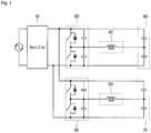
- FIG. 1 is a view illustrating an induction heat cooking apparatus according to a related art.
- FIG. 1 illustrates the induction heat cooking apparatus including two inverters and two heating coils.
- the induction heat cooking apparatus includes a rectifier 10, a first inverter 20, a second inverter 30, a first heating coil 40, a second heating coil 50, a first resonant capacitor 60 and a second resonant capacitor 70.
- Each of the first and second inverters 20 and 30 includes two switching elements which switch input electric power and are connected in series, and the first and second heating coils 40 and 50 driven by an output voltage of the switch elements are connected to each connecting point of the switching elements connected in series. Other sides of the first and second heating coils 40 and 50 are connected to the resonant capacitors 60 and 70.
- Driving of the switching elements is performed by a driving part.
- the switching elements apply a high frequency voltage to each of the heating coils, while being controlled by switching time output from the driving part and thus alternately operated. Since on/off time of each of the switching elements applied from the driving part is controlled with gradual compensation, the voltage supplied to each of the heating coils changes from a low voltage to a high voltage.
- the induction heat cooking apparatus should include two inverter circuits including four switching elements to operate the two heating coils, and thus a volume of a product increases, and a price of the product also increases.
- EP 2 736 305 A2 relates to an induction heating cooker including a rectifier, an inverter, a first heater, a second heater connected in parallel to the first heater, and a switching controller.
- the present invention is directed to an induction heat cooking apparatus having a plurality of heating coils, which is able to be controlled by a minimum number of switching elements, and a method for controlling the same.
- the present invention is also directed to an induction heat cooking apparatus having a plurality of heating coils, in which the plurality of heating coils are able to be driven together by a minimum number of switching elements, and a method for controlling the same.
- the present invention is also directed to an induction heat cooking apparatus which is able to reduce a leakage current generated when a switching element is closed (turned on) or opened (turned off), and thus to reduce heat from a heating coil which is not operated, and a method for controlling the same.
- an induction heat cooking apparatus including a plurality of switching elements; a plurality of heating coils configured to heat a cooking container according to an operation of the plurality of switching elements; and a control part configured to control the plurality of switching elements, wherein the control part controls a time at which the switching element disposed between the heating coil which is operated and the heating coil which is not operated is opened to be earlier than that of another switching element, such that power is not applied to the heating coil which is not operated among the plurality of heating coils.
- the control part may control a closed state of the switching element disposed between the heating coil which is operated and the heating coil which is not operated among the plurality of heating coils to remain shorter than half of a resonant period, and also controls each of the other switching elements to be remain an opened state or the closed state during half of the resonant period.
- the plurality of heating coils may comprise a first heating coil, a second heating coil and a third heating coil
- the plurality of switching elements may comprise a first switching element, a second switching element, a third switching element and a fourth switching element
- the first heating coil may be connected between the first switching element and the second switching element
- the second heating coil is connected between the second switching element and the third switching element
- the third heating coil is connected between the third switching element and the fourth switching element.
- the control part may control the first switching element to be in the closed state, and controls the second, third and fourth switching elements to be in the opened state during half of a resonant period, and also controls the first switching element to be in the opened state, and controls the second, third and fourth switching elements to be in the closed state during the other half of the resonant period, and the control part may control a time at which the second switching element is opened to be earlier than that of the third and fourth switching elements.
- the control part may control the first and second switching elements to be in the closed state, and controls the third and fourth switching elements to be in the opened state during half of a resonant period, and also controls the first and second switching elements to be in the opened state, and controls the third and fourth switching elements to be in the closed state during the other half of the resonant period, and the control part controls a time at which the second and third switching elements are opened to be earlier than that of the first and fourth switching elements.
- the control part may control the first, second and third switching elements to be in the closed state, and controls the fourth switching element to be in the opened state during half of a resonant period, and also controls the first, second and third switching elements to be in the opened state, and controls the fourth switching element to be in the closed state during the other half of the resonant period, and the control part may control a time at which the third switching element is opened to be earlier than that of the first and second switching elements.
- control part may control the other heating coils not to be operated.
- the control part may control a time at which the switching element disposed between the heating coil which is operated and the heating coil which is not operated is switched from a closed state to an opened state to be 1 to 1.5 ms earlier than that of another switching element.
- FIGS. 2 to 10 are views illustrating an induction heat cooking apparatus and a method for controlling the same according to an embodiment of the present invention.
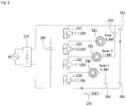
- FIG. 2 is a view illustrating a structure of an induction heat cooking apparatus according to an embodiment of the present invention.
- an induction heat cooking apparatus includes a rectifier 210 in which commercial AC power is input from an outside and the AC power is rectified into DC power, a first switching element 221, a second switching element 222, a third switching element 223 and a fourth switching element 224 which are connected to both ends of a positive power terminal and a negative power terminal of the rectifier 210 and switched according to a control signal, a first heating coil 241 with one end connected to a connecting point between the first switching element 221 and the second switching element 222 and the other end connected between a first resonant capacitor 261 and a second resonant capacitor 262 connected to one end and the other end of the rectifier 210, a second heating coil 242 with one end connected to a connecting point between the second switching element 222 and the third switching element 223 and the other end connected to a third resonant capacitor 263 connected to the other end of the rectifier 210, and a third heating coil 243 with one end connected to a connecting point between the third
- control part which controls switching operations of the switching elements 221, 222, 223 and 224 is further included.
- the embodiment describes an example in which three heating coils are provided.
- N+1 switching elements may be provided, and the heating coils may be driven in a state in which the number of switching elements is minimized.
- One end of the first switching element 221 is connected to the positive power terminal, and the other end thereof is connected to the second switching element 222.
- One end of the second switching element 222 is connected to the first switching element 221 and the other end thereof is connected to the third switching element 223.
- One end of the third switching element 223 is connected to the second switching element 222 and the other end thereof is connected to the fourth switching element 224.
- One end of the fourth switching element 224 is connected to the third switching element 223 and the other end thereof is connected to the negative power terminal.
- a DC capacitor 290 connected to both ends of the rectifier 210 may be further included.
- the DC capacitor 290 serves to reduce ripples in a DC voltage output from the rectifier 210.
- the embodiment has been described as an example in which the first heating coil 241 is connected between the first resonant capacitor 261 and the second resonant capacitor 262.
- the first resonant capacitor 261 or the second resonant capacitor 262 may not be provided.
- the embodiment has been described as an example in which the second heating coil 242 is connected to the third resonant capacitor 263 connected with the positive power terminal, and the third heating coil 243 is connected to the fourth resonant capacitor 264 connected with the negative power terminal.
- the second heating coil 242 may be connected to the fourth resonant capacitor 264 connected with the negative power terminal, and the third heating coil 243 may be connected to the third resonant capacitor 263 connected with the positive power terminal.
- the second heating coil 242 and the third heating coil 243 may be formed to have the same capacity.
- the second heating coil 242 and the third heating coil 243 may be simultaneously driven in parallel.
- Each of the switching elements 221, 222, 223 and 224 may be connected with an antiparallel diode, and a subsidiary resonant capacitor may be connected in parallel with the antiparallel diode to minimize switching loss of each of the switching elements.
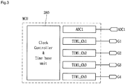
- FIG. 3 is a view illustrating a control part which controls the switching element according to the embodiment of the present invention
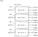
- FIG. 4 is a view illustrating a gate driver which operates the switching element according to the embodiment of the present invention
- FIG. 5 is a view illustrating a switching mode power supply according to the embodiment of the present invention.
- a control part 280 is connected to inputs G1, G2, G3 and G4 of first, second, third and fourth gate drivers 291, 292, 293 and 294 which drive the switching elements 221, 222, 223 and 224, and outputs GD1, GD2, GD3 and GD4 of the gate drivers 291, 292, 293 and 294 are connected to gate ends of the switching elements 221, 222, 223 and 224.
- separate power of a multi-output SMPS is used as power supplied to the gate drivers 291, 292, 293 and 294.
- a signal of the control part 280 may be applied to the gate drivers 291, 292, 293 and 294 to drive a semiconductor switch, and thus each of the switching elements 221, 222, 223 and 224 may be controlled.
- a current converter 270 may be provided between a ground of the switching elements 221, 222, 223 and 224 connected in series and a ground of the first, second and third heating coils 241, 242 and 243.
- the current converter 270 measures a current flowing through the first, second and third heating coils 241, 242 and 243, and enables a current value to be input to the control part 280 via an analog-digital converter (ADC) provided at the control part 280.
- ADC analog-digital converter
- the control part 280 controls the switching elements 221, 222, 223 and 224 based on the current value.
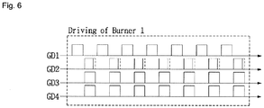
- FIGS. 6 to 8 are views illustrating a signal which drives each heating coil (Burner) in the embodiment of the present invention.
- control part 280 controls the current flowing through the first, second and third heating coils 241, 242 and 243 by controlling the switching elements 221, 222, 223 and 224.
- the first switching element 221 is controlled to be in a closed state, and the second, third and fourth switching elements 222, 223 and 224 are controlled to be in an opened state during half of a resonant period.
- the first switching element 221 is controlled to be in the opened state, and the second, third and fourth switching elements 222, 223 and 224 are controlled to be in the closed state.
- the resonant period is a reciprocal number of a resonant frequency, and the resonant frequency may be determined by reactance and capacitance values of the circuit.
- the induction heat cooking apparatus of the present invention has a resonant frequency of about 20 to 70 kHz. Therefore, when the resonant frequency is 20 kHz, the resonant period is 5 ms.
- an input voltage is applied to the first heating coil 241 and the first and second resonant capacitors 261 and 262 through the above-described operation, and thus resonance is started, and a current of the first heating coil 241 is increased.
- the input voltage is reversely applied to the first heating coil 241 and the first and second resonant capacitors 261 and 262, and thus the resonance is started, and a reverse directional current of the first heating coil 241 is increased.
- a leakage current leaking to the second and third heating coils 242 and 243 may be reduced through a method in which a time at which the second switching element 222 of the first switching element 221 and the second switching element 222 connected with the first heating coil 241, which is disposed between the first heating coil 241 and the second heating coil 242, is switched from the closed state to the opened state is earlier than that of the third and fourth switching elements 223 and 224.
- the time at which the second switching element 222 is switched to the opened state may be set to about 1 to 1.5 ms earlier, but is not limited thereto.
- the leakage current flowing through the second heating coil 242 or the third heating coil 243 which is not operated may be reduced. Therefore, unnecessary power consumption and temperature rise may be prevented by reducing the leakage current flowing through the second heating coil 242 or the third heating coil 243.
- the first switching element 221 and the second switching element 222 are controlled to be in the closed state, and the third and fourth switching elements 223 and 224 are controlled to be in the opened state during the half of the resonant period.
- the first switching element 221 and the second switching element 222 are controlled to be in the opened state, and the third and fourth switching elements 223 and 224 are controlled to be in the closed state.
- the input voltage is applied to the second heating coil 242 and the third resonant capacitor 263 through the above-described operation, and thus the resonance is started, and a current of the second heating coil 242 is increased.
- the input voltage is reversely applied to the second heating coil 242 and the third resonant capacitor 263, and thus the resonance is started, and a reverse directional current of the second heating coil 242 is increased.
- the leakage current leaking to the first heating coil 241 or the third heating coil 243 may be reduced through a method in which a time at which the second switching element 222 and the third switching element 223 connected with the second heating coil 242 is switched from the closed state to the opened state is earlier than that of the first switching element 221 or the fourth switching element 224.
- the leakage current flowing through the first heating coil 241 or the third heating coil 243 which is not operated may be reduced. Therefore, the unnecessary power consumption and temperature rise may be prevented by reducing the leakage current flowing through the first heating coil 241 or the third heating coil 243.
- the first, second and third switching elements 221, 222 and 223 are controlled to be in the closed state, and the fourth switching element 224 is controlled to be in the opened state during the half of the resonant period.
- the first, second and third switching elements 221, 222 and 223 are controlled to be in the opened state, and the fourth switching element 224 is controlled to be in the closed state.
- the input voltage is applied to the third heating coil 243 and the fourth resonant capacitor 264 through the above-described operation, and thus the resonance is started, and a current of the third heating coil 243 is increased.
- the input voltage is reversely applied to the third heating coil 243 and the fourth resonant capacitor 264, and thus the resonance is started, and a reverse directional current of the third heating coil 243 is increased.
- the leakage current leaking to the first heating coil 241 or the second heating coil 242 may be reduced through a method in which a time at which the third switching element 223 of the third switching element 223 and the fourth switching element 224 connected with the third heating coil 243, which is disposed between the second heating coil 242 and the third heating coil 243, is switched from the closed state to the opened state is earlier.
- the leakage current flowing through the first heating coil 241 or the second heating coil 242 which is not operated may be reduced. Therefore, the unnecessary power consumption and temperature rise may be prevented by reducing the leakage current flowing through the first heating coil 241 or the second heating coil 242.
- the control part 280 controls the remaining heating coils not to be operated. Therefore, when a user intends to simultaneously operates the plurality of heating coils, the control part 280 may simultaneously increase a temperature of each of the plurality of heating coils by alternately operating the heating coils which are intended to be simultaneously operated for short periods.
- the induction heat cooking apparatus since the induction heat cooking apparatus according to the embodiment has the plurality of heating coils and the minimum switching elements for driving the plurality of heating coils, it is possible to reduce a size of the induction heat cooking apparatus and also to reduce a manufacturing cost.
- the induction heat cooking apparatus may reduce the leakage current through a method in which the time at which the switching element disposed between the heating coil to be operated and the adjacent heating coil is switching to the opened state is earlier.
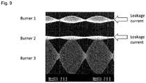
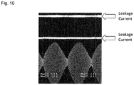
- FIGS. 9 and 10 are views illustrating the leakage current when the time at which the switching element is opened in the related art is not earlier, and the leakage current when the time at which the switching element is opened in the embodiment of the present invention is earlier.
- the leakage current flowing to the first heating coil 241 indicated by Burner 1 and the second heating coil 242 indicated by Burner 2 may be reduced, and since a maximum value of the leakage current flowing to the first heating coil 241 and the second heating coil 242 is proportional to the power applied to the first heating coil 241 and the second heating coil 242, the unnecessary temperature rise may be prevented.
- Embodiments of the present invention can provide the induction heat cooking apparatus having the plurality of heating coils, which is able to be controlled by the minimum number of switching elements, and the method for controlling the same.
- embodiments of the present invention can provide the induction heat cooking apparatus having the plurality of heating coils, in which the plurality of heating coils are able to be driven together by the minimum number of switching elements, and the method for controlling the same.
- embodiments of the present invention can provide the induction heat cooking apparatus which can reduce the leakage current generated when the switching element is closed (turned on) or opened (turned off), and thus can reduce the heat from the heating coil which is not operated, and the method for controlling the same.
Landscapes
- Physics & Mathematics (AREA)
- Electromagnetism (AREA)
- Engineering & Computer Science (AREA)
- Food Science & Technology (AREA)
- Induction Heating Cooking Devices (AREA)
- Chemical & Material Sciences (AREA)
- Combustion & Propulsion (AREA)
- Mechanical Engineering (AREA)
- General Engineering & Computer Science (AREA)
- Power Engineering (AREA)
Claims (6)
- Induktionserwärme-Kochvorrichtung mit:einem Gleichrichter (210), der konfiguriert ist, eine Eingangsspannung gleichzurichten und eine Gleichspannung abzugeben;mehreren Schaltelementen (221, 222, 223, 224), die konfiguriert sind, die durch den Gleichrichter abgegebene Gleichspannung zu schalten;mehreren Heizspulen (241, 242, 243), die konfiguriert sind, betrieben zu werden, um ein Kochgefäß gemäß einem Betrieb der mehreren Schaltelemente (221, 222, 223, 224) zu erwärmen; undeinem Steuerteil (280), das konfiguriert ist, die mehreren Schaltelemente (221, 222, 223, 224) zu steuern,wobei das Steuerteil (280) eine Zeit, zu der ein Schaltelement, das zwischen einer Heizspule, die betrieben wird, und einer Heizspule angeordnet ist, die nicht betrieben wird, unter den mehreren Heizspulen (241, 242, 243) geöffnet ist, so steuert, dass sie früher als eine jeweilige Zeit für andere Schaltelemente ist, so dass kein Strom an die Heizspule, die nicht betrieben wird, unter den mehreren Heizspulen (241, 242, 243) angelegt wird,dadurch gekennzeichnet, dassdie mehreren Heizspulen (241, 242, 243) eine erste Heizspule (241), eine zweite Heizspule (242) und eine dritte Heizspule (243) aufweisen,wobei die mehreren Schaltelemente (221, 222, 223, 224) ein erstes Schaltelement (221), ein zweites Schaltelement (222), ein drittes Schaltelement (223) und ein viertes Schaltelement (224) aufweisen,wobei die erste Heizspule (241) zwischen dem ersten Schaltelement (221) und dem zweiten Schaltelement (222) geschaltet ist, und die zweite Heizspule (242) zwischen dem zweiten Schaltelement (222) und dem dritten Schaltelement (223) geschaltet ist, und die dritte Heizspule (243) zwischen dem dritten Schaltelement (223) und dem vierten Schaltelement (224) geschaltet ist,wobei, wenn die erste Heizspule (241) betrieben wird, das Steuerteil (280) das erste Schaltelement (221) so steuert, dass es sich im geschlossenen Zustand befindet, und das zweite, dritte und vierte Schaltelement (222, 223, 224) so steuert, dass sie sich während einer Hälfte einer Resonanzperiode im geöffneten Zustand befinden, und außerdem das erste Schaltelement (221) so steuert, dass es sich im geöffneten Zustand befindet, und das zweite, dritte und vierte Schaltelement (222, 223, 224) so steuert, dass sie sich während der anderen Hälfte der Resonanzperiode im geschlossenen Zustand befinden, undwobei das Steuerteil (280) eine Zeit, zu der das zweite Schaltelement (222) geöffnet ist, so steuert, dass sie früher als die des dritten und vierten Schaltelements (223, 224) ist.
- Vorrichtung nach Anspruch 1, wobei das Steuerteil (280) das Schaltelement, das zwischen der Heizspule, die betrieben wird, und der Heizspule angeordnet ist, die nicht betrieben wird, unter den mehreren Heizspulen (241, 242, 243) so steuert, dass es für eine kürzere Zeit als eine Hälfte einer Resonanzperiode in einem geschlossenen Zustand bleibt, und außerdem jedes der anderen Schaltelemente so steuert, dass sie während der Hälfte der Resonanzperiode in einem geöffneten Zustand oder dem geschlossenen Zustand bleiben.
- Vorrichtung nach Anspruch 1 oder 2, wobei, wenn die zweite Heizspule (242) betrieben wird, das Steuerteil (280) das erste und zweite Schaltelement (221, 222) so steuert, dass sie sich im geschlossenen Zustand befinden, und das dritte und vierte Schaltelement (223, 224) so steuert, dass sie sich während einer Hälfte einer Resonanzperiode im geöffneten Zustand befinden, und außerdem das erste und zweite Schaltelement (221, 222) so steuert, dass sie sich im geöffneten Zustand befinden, und das dritte und vierte Schaltelement (223, 224) so steuert, dass sie sich während der anderen Hälfte der Resonanzperiode im geschlossenen Zustand befinden, und
wobei das Steuerteil (280) eine Zeit, zu der das zweite und dritte Schaltelement (222, 223) geöffnet sind, so steuert, dass sie früher als die des ersten und vierten Schaltelements (221, 224) ist. - Vorrichtung nach Anspruch 1 oder 2, wobei, wenn die dritte Heizspule (243) betrieben wird, das Steuerteil (280) das erste, zweite und dritte Schaltelement (221, 222, 223) so steuert, dass sie sich im geschlossenen Zustand befinden, und das vierte Schaltelement (224) so steuert, dass es sich während einer Hälfte einer Resonanzperiode im geöffneten Zustand befindet, und außerdem das erste, zweite und dritte Schaltelement (221, 222, 223) so steuert, dass sie sich im geöffneten Zustand befinden, und das vierte Schaltelement (224) so steuert, dass es sich während der anderen Hälfte der Resonanzperiode im geschlossenen Zustand befindet, und
wobei das Steuerteil (280) eine Zeit, zu der das dritte Schaltelement (223) geöffnet ist, so steuert, dass sie früher als die des ersten und zweiten Schaltelements (221, 222) ist. - Vorrichtung nach einem der vorhergehenden Ansprüche, wobei, wenn eine Heizspule der mehreren Heizspulen (241, 242, 243) betrieben wird, das Steuerteil (280) die anderen Heizspulen so steuert, dass sie nicht betrieben werden.
- Vorrichtung nach einem der vorhergehenden Ansprüche, wobei das Steuerteil (280) eine Zeit, zu der das Schaltelement, das zwischen einer Heizspule, die betrieben wird, und einer Heizspule angeordnet ist, die nicht betrieben wird, vom einem geschlossenen Zustand in einen geöffneten Zustand umgeschaltet wird, so steuert, dass sie 1 bis 1,5 ms früher als die eines anderen Schaltelements ist.
Applications Claiming Priority (1)
| Application Number | Priority Date | Filing Date | Title |
|---|---|---|---|
| KR1020150088602A KR102326999B1 (ko) | 2015-06-22 | 2015-06-22 | 전자 유도 가열 조리기 및 이의 구동 방법 |
Publications (2)
| Publication Number | Publication Date |
|---|---|
| EP3110232A1 EP3110232A1 (de) | 2016-12-28 |
| EP3110232B1 true EP3110232B1 (de) | 2020-08-05 |
Family
ID=56116358
Family Applications (1)
| Application Number | Title | Priority Date | Filing Date |
|---|---|---|---|
| EP16173663.2A Active EP3110232B1 (de) | 2015-06-22 | 2016-06-09 | Induktionswärmegarvorrichtung und verfahren zur ansteuerung davon |
Country Status (3)
| Country | Link |
|---|---|
| US (1) | US10582574B2 (de) |
| EP (1) | EP3110232B1 (de) |
| KR (1) | KR102326999B1 (de) |
Families Citing this family (6)
| Publication number | Priority date | Publication date | Assignee | Title |
|---|---|---|---|---|
| WO2014069363A1 (ja) * | 2012-11-02 | 2014-05-08 | ローム株式会社 | チップコンデンサ、回路アセンブリ、および電子機器 |
| JP2017050275A (ja) * | 2015-09-02 | 2017-03-09 | カルソニックカンセイ株式会社 | 加熱装置 |
| KR102016219B1 (ko) * | 2017-09-29 | 2019-08-29 | 엘지전자 주식회사 | 대상체 검출 알고리즘이 개선된 유도 가열 및 무선 전력 전송 장치 |
| US10993292B2 (en) * | 2017-10-23 | 2021-04-27 | Whirlpool Corporation | System and method for tuning an induction circuit |
| CN109945247B (zh) | 2017-12-21 | 2020-05-05 | 佛山市顺德区美的电热电器制造有限公司 | 电磁烹饪器具及其功率控制方法 |
| EP4013191B1 (de) | 2020-12-11 | 2026-01-07 | BSH Hausgeräte GmbH | Induktionsgargerätevorrichtung |
Family Cites Families (11)
| Publication number | Priority date | Publication date | Assignee | Title |
|---|---|---|---|---|
| US591904A (en) | 1897-10-19 | Combination bracket and luggage-carrier for bicycles | ||
| JP2004235032A (ja) * | 2003-01-30 | 2004-08-19 | Mitsubishi Electric Corp | 誘導加熱調理器 |
| EP2209197A1 (de) * | 2009-01-16 | 2010-07-21 | Whirpool Corporation | Verfahren zur Steuerung von Resonanzleistungswandlern in Induktionsheizsystemen und Induktionsheizsystem zur Durchführung eines solchen Verfahrens |
| ES2536432T3 (es) * | 2010-01-20 | 2015-05-25 | Panasonic Corporation | Aparato de calentamiento por inducción |
| KR20110092891A (ko) * | 2010-02-10 | 2011-08-18 | 삼성전자주식회사 | 유도가열조리기 |
| KR101844404B1 (ko) * | 2011-03-28 | 2018-04-03 | 삼성전자주식회사 | 유도가열조리기 |
| WO2013084386A1 (ja) * | 2011-12-06 | 2013-06-13 | パナソニック株式会社 | 誘導加熱装置 |
| KR102009354B1 (ko) | 2012-11-26 | 2019-08-09 | 엘지전자 주식회사 | 전자 유도 가열 조리기 및 이의 구동 방법 |
| KR102031875B1 (ko) * | 2013-01-02 | 2019-10-14 | 엘지전자 주식회사 | 전자 유도 가열 조리기 및 이의 구동 방법 |
| US10187930B2 (en) | 2014-10-02 | 2019-01-22 | Lg Electronics Inc. | Induction heat cooking apparatus |
| EP3002991B1 (de) | 2014-10-02 | 2022-07-13 | LG Electronics Inc. | Induktionswärmekochvorrichtung |
-
2015
- 2015-06-22 KR KR1020150088602A patent/KR102326999B1/ko active Active
-
2016
- 2016-02-19 US US15/048,371 patent/US10582574B2/en active Active
- 2016-06-09 EP EP16173663.2A patent/EP3110232B1/de active Active
Non-Patent Citations (1)
| Title |
|---|
| None * |
Also Published As
| Publication number | Publication date |
|---|---|
| US20160374151A1 (en) | 2016-12-22 |
| EP3110232A1 (de) | 2016-12-28 |
| KR20160150508A (ko) | 2016-12-30 |
| US10582574B2 (en) | 2020-03-03 |
| KR102326999B1 (ko) | 2021-11-16 |
Similar Documents
| Publication | Publication Date | Title |
|---|---|---|
| EP3002991B1 (de) | Induktionswärmekochvorrichtung | |
| EP3110232A1 (de) | Induktionswärmegarvorrichtung und verfahren zur ansteuerung davon | |
| KR102031875B1 (ko) | 전자 유도 가열 조리기 및 이의 구동 방법 | |
| EP3002992B1 (de) | Induktionswärmekochvorrichtung | |
| KR102009354B1 (ko) | 전자 유도 가열 조리기 및 이의 구동 방법 | |
| KR20090048789A (ko) | 유도가열조리기 | |
| KR102009344B1 (ko) | 전자 유도 가열 조리기 및 이의 출력 레벨 제어 방법 | |
| EP2753147B1 (de) | Induktionswärmekochvorrichtung | |
| US20180063891A1 (en) | Induction heating device | |
| EP3675599B1 (de) | Induktionserwärmungsherd | |
| US10477629B2 (en) | Induction heat cooking apparatus and method for driving the same | |
| KR102306811B1 (ko) | 전자 유도 가열 조리기 및 이의 구동 방법 | |
| US10681780B2 (en) | Induction heat cooking apparatus | |
| US10667333B2 (en) | Induction heat cooking apparatus | |
| KR102329539B1 (ko) | 전자 유도 가열 조리기 및 이의 구동 방법 | |
| KR102182624B1 (ko) | 전자 유도 가열 조리기 및 이의 구동 방법 | |
| KR101757976B1 (ko) | 전자 유도 가열 조리기 및 이의 구동 방법 | |
| JP6854428B2 (ja) | インバータ装置およびその制御方法 | |
| JP2004288602A (ja) | 誘導加熱装置 |
Legal Events
| Date | Code | Title | Description |
|---|---|---|---|
| PUAI | Public reference made under article 153(3) epc to a published international application that has entered the european phase |
Free format text: ORIGINAL CODE: 0009012 |
|
| STAA | Information on the status of an ep patent application or granted ep patent |
Free format text: STATUS: REQUEST FOR EXAMINATION WAS MADE |
|
| 17P | Request for examination filed |
Effective date: 20160709 |
|
| AK | Designated contracting states |
Kind code of ref document: A1 Designated state(s): AL AT BE BG CH CY CZ DE DK EE ES FI FR GB GR HR HU IE IS IT LI LT LU LV MC MK MT NL NO PL PT RO RS SE SI SK SM TR |
|
| AX | Request for extension of the european patent |
Extension state: BA ME |
|
| RBV | Designated contracting states (corrected) |
Designated state(s): AL AT BE BG CH CY CZ DE DK EE ES FI FR GB GR HR HU IE IS IT LI LT LU LV MC MK MT NL NO PL PT RO RS SE SI SK SM TR |
|
| GRAP | Despatch of communication of intention to grant a patent |
Free format text: ORIGINAL CODE: EPIDOSNIGR1 |
|
| STAA | Information on the status of an ep patent application or granted ep patent |
Free format text: STATUS: GRANT OF PATENT IS INTENDED |
|
| INTG | Intention to grant announced |
Effective date: 20191209 |
|
| GRAJ | Information related to disapproval of communication of intention to grant by the applicant or resumption of examination proceedings by the epo deleted |
Free format text: ORIGINAL CODE: EPIDOSDIGR1 |
|
| STAA | Information on the status of an ep patent application or granted ep patent |
Free format text: STATUS: REQUEST FOR EXAMINATION WAS MADE |
|
| GRAR | Information related to intention to grant a patent recorded |
Free format text: ORIGINAL CODE: EPIDOSNIGR71 |
|
| GRAS | Grant fee paid |
Free format text: ORIGINAL CODE: EPIDOSNIGR3 |
|
| STAA | Information on the status of an ep patent application or granted ep patent |
Free format text: STATUS: GRANT OF PATENT IS INTENDED |
|
| INTC | Intention to grant announced (deleted) | ||
| INTG | Intention to grant announced |
Effective date: 20200511 |
|
| GRAA | (expected) grant |
Free format text: ORIGINAL CODE: 0009210 |
|
| STAA | Information on the status of an ep patent application or granted ep patent |
Free format text: STATUS: THE PATENT HAS BEEN GRANTED |
|
| AK | Designated contracting states |
Kind code of ref document: B1 Designated state(s): AL AT BE BG CH CY CZ DE DK EE ES FI FR GB GR HR HU IE IS IT LI LT LU LV MC MK MT NL NO PL PT RO RS SE SI SK SM TR |
|
| REG | Reference to a national code |
Ref country code: GB Ref legal event code: FG4D |
|
| REG | Reference to a national code |
Ref country code: CH Ref legal event code: EP |
|
| REG | Reference to a national code |
Ref country code: AT Ref legal event code: REF Ref document number: 1300547 Country of ref document: AT Kind code of ref document: T Effective date: 20200815 |
|
| REG | Reference to a national code |
Ref country code: DE Ref legal event code: R096 Ref document number: 602016041193 Country of ref document: DE |
|
| REG | Reference to a national code |
Ref country code: IE Ref legal event code: FG4D |
|
| REG | Reference to a national code |
Ref country code: LT Ref legal event code: MG4D |
|
| REG | Reference to a national code |
Ref country code: NL Ref legal event code: MP Effective date: 20200805 |
|
| REG | Reference to a national code |
Ref country code: AT Ref legal event code: MK05 Ref document number: 1300547 Country of ref document: AT Kind code of ref document: T Effective date: 20200805 |
|
| PG25 | Lapsed in a contracting state [announced via postgrant information from national office to epo] |
Ref country code: PT Free format text: LAPSE BECAUSE OF FAILURE TO SUBMIT A TRANSLATION OF THE DESCRIPTION OR TO PAY THE FEE WITHIN THE PRESCRIBED TIME-LIMIT Effective date: 20201207 Ref country code: ES Free format text: LAPSE BECAUSE OF FAILURE TO SUBMIT A TRANSLATION OF THE DESCRIPTION OR TO PAY THE FEE WITHIN THE PRESCRIBED TIME-LIMIT Effective date: 20200805 Ref country code: NO Free format text: LAPSE BECAUSE OF FAILURE TO SUBMIT A TRANSLATION OF THE DESCRIPTION OR TO PAY THE FEE WITHIN THE PRESCRIBED TIME-LIMIT Effective date: 20201105 Ref country code: GR Free format text: LAPSE BECAUSE OF FAILURE TO SUBMIT A TRANSLATION OF THE DESCRIPTION OR TO PAY THE FEE WITHIN THE PRESCRIBED TIME-LIMIT Effective date: 20201106 Ref country code: SE Free format text: LAPSE BECAUSE OF FAILURE TO SUBMIT A TRANSLATION OF THE DESCRIPTION OR TO PAY THE FEE WITHIN THE PRESCRIBED TIME-LIMIT Effective date: 20200805 Ref country code: HR Free format text: LAPSE BECAUSE OF FAILURE TO SUBMIT A TRANSLATION OF THE DESCRIPTION OR TO PAY THE FEE WITHIN THE PRESCRIBED TIME-LIMIT Effective date: 20200805 Ref country code: FI Free format text: LAPSE BECAUSE OF FAILURE TO SUBMIT A TRANSLATION OF THE DESCRIPTION OR TO PAY THE FEE WITHIN THE PRESCRIBED TIME-LIMIT Effective date: 20200805 Ref country code: LT Free format text: LAPSE BECAUSE OF FAILURE TO SUBMIT A TRANSLATION OF THE DESCRIPTION OR TO PAY THE FEE WITHIN THE PRESCRIBED TIME-LIMIT Effective date: 20200805 Ref country code: BG Free format text: LAPSE BECAUSE OF FAILURE TO SUBMIT A TRANSLATION OF THE DESCRIPTION OR TO PAY THE FEE WITHIN THE PRESCRIBED TIME-LIMIT Effective date: 20201105 Ref country code: AT Free format text: LAPSE BECAUSE OF FAILURE TO SUBMIT A TRANSLATION OF THE DESCRIPTION OR TO PAY THE FEE WITHIN THE PRESCRIBED TIME-LIMIT Effective date: 20200805 |
|
| PG25 | Lapsed in a contracting state [announced via postgrant information from national office to epo] |
Ref country code: NL Free format text: LAPSE BECAUSE OF FAILURE TO SUBMIT A TRANSLATION OF THE DESCRIPTION OR TO PAY THE FEE WITHIN THE PRESCRIBED TIME-LIMIT Effective date: 20200805 Ref country code: PL Free format text: LAPSE BECAUSE OF FAILURE TO SUBMIT A TRANSLATION OF THE DESCRIPTION OR TO PAY THE FEE WITHIN THE PRESCRIBED TIME-LIMIT Effective date: 20200805 Ref country code: RS Free format text: LAPSE BECAUSE OF FAILURE TO SUBMIT A TRANSLATION OF THE DESCRIPTION OR TO PAY THE FEE WITHIN THE PRESCRIBED TIME-LIMIT Effective date: 20200805 Ref country code: LV Free format text: LAPSE BECAUSE OF FAILURE TO SUBMIT A TRANSLATION OF THE DESCRIPTION OR TO PAY THE FEE WITHIN THE PRESCRIBED TIME-LIMIT Effective date: 20200805 Ref country code: IS Free format text: LAPSE BECAUSE OF FAILURE TO SUBMIT A TRANSLATION OF THE DESCRIPTION OR TO PAY THE FEE WITHIN THE PRESCRIBED TIME-LIMIT Effective date: 20201205 |
|
| PG25 | Lapsed in a contracting state [announced via postgrant information from national office to epo] |
Ref country code: EE Free format text: LAPSE BECAUSE OF FAILURE TO SUBMIT A TRANSLATION OF THE DESCRIPTION OR TO PAY THE FEE WITHIN THE PRESCRIBED TIME-LIMIT Effective date: 20200805 Ref country code: DK Free format text: LAPSE BECAUSE OF FAILURE TO SUBMIT A TRANSLATION OF THE DESCRIPTION OR TO PAY THE FEE WITHIN THE PRESCRIBED TIME-LIMIT Effective date: 20200805 Ref country code: CZ Free format text: LAPSE BECAUSE OF FAILURE TO SUBMIT A TRANSLATION OF THE DESCRIPTION OR TO PAY THE FEE WITHIN THE PRESCRIBED TIME-LIMIT Effective date: 20200805 Ref country code: RO Free format text: LAPSE BECAUSE OF FAILURE TO SUBMIT A TRANSLATION OF THE DESCRIPTION OR TO PAY THE FEE WITHIN THE PRESCRIBED TIME-LIMIT Effective date: 20200805 Ref country code: SM Free format text: LAPSE BECAUSE OF FAILURE TO SUBMIT A TRANSLATION OF THE DESCRIPTION OR TO PAY THE FEE WITHIN THE PRESCRIBED TIME-LIMIT Effective date: 20200805 |
|
| REG | Reference to a national code |
Ref country code: DE Ref legal event code: R097 Ref document number: 602016041193 Country of ref document: DE |
|
| PG25 | Lapsed in a contracting state [announced via postgrant information from national office to epo] |
Ref country code: AL Free format text: LAPSE BECAUSE OF FAILURE TO SUBMIT A TRANSLATION OF THE DESCRIPTION OR TO PAY THE FEE WITHIN THE PRESCRIBED TIME-LIMIT Effective date: 20200805 |
|
| PLBE | No opposition filed within time limit |
Free format text: ORIGINAL CODE: 0009261 |
|
| STAA | Information on the status of an ep patent application or granted ep patent |
Free format text: STATUS: NO OPPOSITION FILED WITHIN TIME LIMIT |
|
| PG25 | Lapsed in a contracting state [announced via postgrant information from national office to epo] |
Ref country code: SK Free format text: LAPSE BECAUSE OF FAILURE TO SUBMIT A TRANSLATION OF THE DESCRIPTION OR TO PAY THE FEE WITHIN THE PRESCRIBED TIME-LIMIT Effective date: 20200805 |
|
| 26N | No opposition filed |
Effective date: 20210507 |
|
| PG25 | Lapsed in a contracting state [announced via postgrant information from national office to epo] |
Ref country code: IT Free format text: LAPSE BECAUSE OF FAILURE TO SUBMIT A TRANSLATION OF THE DESCRIPTION OR TO PAY THE FEE WITHIN THE PRESCRIBED TIME-LIMIT Effective date: 20200805 |
|
| PG25 | Lapsed in a contracting state [announced via postgrant information from national office to epo] |
Ref country code: SI Free format text: LAPSE BECAUSE OF FAILURE TO SUBMIT A TRANSLATION OF THE DESCRIPTION OR TO PAY THE FEE WITHIN THE PRESCRIBED TIME-LIMIT Effective date: 20200805 |
|
| PG25 | Lapsed in a contracting state [announced via postgrant information from national office to epo] |
Ref country code: MC Free format text: LAPSE BECAUSE OF FAILURE TO SUBMIT A TRANSLATION OF THE DESCRIPTION OR TO PAY THE FEE WITHIN THE PRESCRIBED TIME-LIMIT Effective date: 20200805 |
|
| REG | Reference to a national code |
Ref country code: CH Ref legal event code: PL |
|
| GBPC | Gb: european patent ceased through non-payment of renewal fee |
Effective date: 20210609 |
|
| REG | Reference to a national code |
Ref country code: BE Ref legal event code: MM Effective date: 20210630 |
|
| PG25 | Lapsed in a contracting state [announced via postgrant information from national office to epo] |
Ref country code: LU Free format text: LAPSE BECAUSE OF NON-PAYMENT OF DUE FEES Effective date: 20210609 |
|
| PG25 | Lapsed in a contracting state [announced via postgrant information from national office to epo] |
Ref country code: LI Free format text: LAPSE BECAUSE OF NON-PAYMENT OF DUE FEES Effective date: 20210630 Ref country code: IE Free format text: LAPSE BECAUSE OF NON-PAYMENT OF DUE FEES Effective date: 20210609 Ref country code: GB Free format text: LAPSE BECAUSE OF NON-PAYMENT OF DUE FEES Effective date: 20210609 Ref country code: CH Free format text: LAPSE BECAUSE OF NON-PAYMENT OF DUE FEES Effective date: 20210630 |
|
| PG25 | Lapsed in a contracting state [announced via postgrant information from national office to epo] |
Ref country code: FR Free format text: LAPSE BECAUSE OF NON-PAYMENT OF DUE FEES Effective date: 20210630 |
|
| PG25 | Lapsed in a contracting state [announced via postgrant information from national office to epo] |
Ref country code: BE Free format text: LAPSE BECAUSE OF NON-PAYMENT OF DUE FEES Effective date: 20210630 |
|
| PG25 | Lapsed in a contracting state [announced via postgrant information from national office to epo] |
Ref country code: HU Free format text: LAPSE BECAUSE OF FAILURE TO SUBMIT A TRANSLATION OF THE DESCRIPTION OR TO PAY THE FEE WITHIN THE PRESCRIBED TIME-LIMIT; INVALID AB INITIO Effective date: 20160609 |
|
| PG25 | Lapsed in a contracting state [announced via postgrant information from national office to epo] |
Ref country code: CY Free format text: LAPSE BECAUSE OF FAILURE TO SUBMIT A TRANSLATION OF THE DESCRIPTION OR TO PAY THE FEE WITHIN THE PRESCRIBED TIME-LIMIT Effective date: 20200805 |
|
| PG25 | Lapsed in a contracting state [announced via postgrant information from national office to epo] |
Ref country code: MK Free format text: LAPSE BECAUSE OF FAILURE TO SUBMIT A TRANSLATION OF THE DESCRIPTION OR TO PAY THE FEE WITHIN THE PRESCRIBED TIME-LIMIT Effective date: 20200805 |
|
| PG25 | Lapsed in a contracting state [announced via postgrant information from national office to epo] |
Ref country code: MT Free format text: LAPSE BECAUSE OF FAILURE TO SUBMIT A TRANSLATION OF THE DESCRIPTION OR TO PAY THE FEE WITHIN THE PRESCRIBED TIME-LIMIT Effective date: 20200805 |
|
| PGFP | Annual fee paid to national office [announced via postgrant information from national office to epo] |
Ref country code: DE Payment date: 20250508 Year of fee payment: 10 |
|
| PG25 | Lapsed in a contracting state [announced via postgrant information from national office to epo] |
Ref country code: TR Free format text: LAPSE BECAUSE OF FAILURE TO SUBMIT A TRANSLATION OF THE DESCRIPTION OR TO PAY THE FEE WITHIN THE PRESCRIBED TIME-LIMIT Effective date: 20200805 |